Motorola Solutions 89FT4883 Portable 2-Way Radio User Manual Beacon LKP NALA
Motorola Solutions, Inc. Portable 2-Way Radio Beacon LKP NALA
Users Manual
CP185 Series
Two-Way Portable Radio
User’s Guide
CP185
M

i English
CONTENTS
CONTENTS
Computer Software Copyrights . . . . . . . . ii
Safety . . . . . . . . . . . . . . . . . . . . . . . . . . . . . iii
Radio Overview . . . . . . . . . . . . . . . . . . . . . . 1
LED Colors . . . . . . . . . . . . . . . . . . . . . . . . . . 3
LCD Display and Icons . . . . . . . . . . . . . . . . . 4
Programmable Buttons. . . . . . . . . . . . . . . . . . 5
Getting Started . . . . . . . . . . . . . . . . . . . . . . . 7
Attaching and Removing the Antenna . . . . . 7
Attaching and Removing the Battery . . . . . . 8
Attaching and Removing the Belt Clip . . . . 9
Charging the Battery . . . . . . . . . . . . . . . . . . 10
Scan . . . . . . . . . . . . . . . . . . . . . . . . . . . . . . 12
Deleting a Nuisance Scan Channel . . . . . . . 12
Voice Operated Transmit (VOX) . . . . . . . . 13
Voice Inversion Scrambling . . . . . . . . . . . 14
Front Panel Programming Mode . . . . . . . .15
Entering Front Panel Programming
Mode . . . . . . . . . . . . . . . . . . . . . . . . . . . . . .15
Exiting Front Panel Programming Mode . . . .15
Assessing Front Panel Programming
Mode Parameters . . . . . . . . . . . . . . . . . . . .15
TPL and DPL Frequencies and Codes . . . . .21
TPL Frequency . . . . . . . . . . . . . . . . . . . . . . 21
DPL Codes . . . . . . . . . . . . . . . . . . . . . . . . . 23
Motorola Limited Warranty for the United
States and Canada . . . . . . . . . . . . . . . . . . .26
Accessories . . . . . . . . . . . . . . . . . . . . . . . .31

ii
COMPUTER SOFTWARE
COPYRIGHTS
English
COMPUTER SOFTWARE
COPYRIGHTS
The Motorola products described in this manual may
include copyrighted Motorola computer programs stored
in semiconductor memories or other media. Laws in the
United States and other countries preserve for Motorola
certain exclusive rights for copyrighted computer
programs, including, but not limited to, the exclusive right
to copy or reproduce in any form the copyrighted
computer program. Accordingly, any copyrighted
Motorola computer programs contained in the Motorola
products described in this manual may not be copied,
reproduced, modified, reverse-engineered, or distributed
in any manner without the express written permission of
Motorola.
Furthermore, the purchase of Motorola products shall not
be deemed to grant either directly or by implication,
estoppel, or otherwise, any license under the copyrights,
patents or patent applications of Motorola, except for the
normal non-exclusive license to use that arises by
operation of law in the sale of a product.

SAFETY
iii English
SAFETY
PRODUCT SAFETY AND RF EXPOSURE
COMPLIANCE
ATTENTION!
This radio is restricted to occupational use only to
satisfy FCC RF energy exposure requirements. Before
using this product, read the RF energy awareness
information and operating instructions in the Product
Safety and RF Exposure booklet enclosed with your radio
(Motorola Publication part number 6881095C98_) to
ensure compliance with RF energy exposure limits.
Before using this product, read the
operating instructions for safe usage
contained in the Product Safety and RF
Exposure booklet enclosed with your radio.
!
C a u t i o n

SAFETY
iv
English
Notes:
1English
RADIO OVERVIEW
English
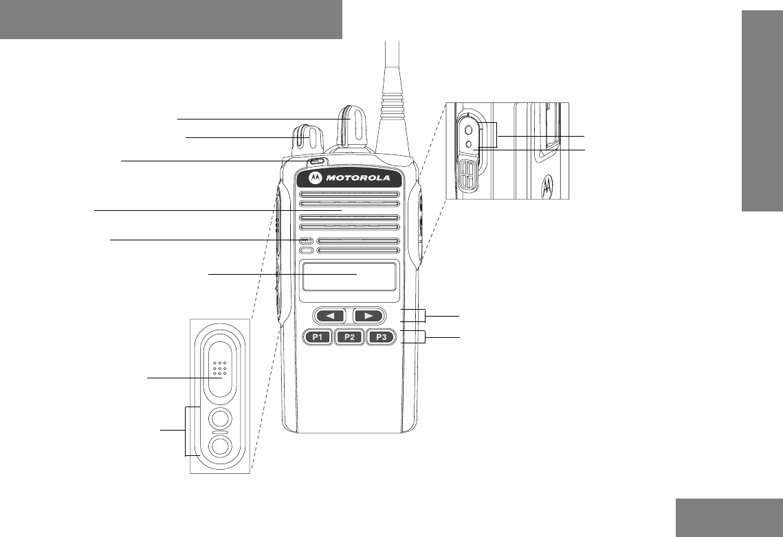
RADIO OVERVIEW
CP185
9 Accessory Connecto
r
10 Programming Port
12 Front Programmable Buttons
11 Front Left/Right Buttons
5 Microphone
6 Liquid Crystal Display (LCD)
1 Channel Selector Knob
2 On/Off and Volume Knob
3 LED Indicator
7 Push-to-Talk (PTT) Button
4 Speaker
8 Side Programmable Buttons

RADIO OVERVIEW
2English
English
1. Channel Selector Knob
Used to select channels in normal radio operation mode.
2. On/Off and Volume Knob
Turn the ON/OFF/Volume Control knob clockwise to turn
the radio ON.
Turn the ON/OFF/Volume Control knob
counterclockwise to turn the radio OFF.
Turn this knob clockwise to increase the volume.
Turn this knob counterclockwise to decrease the volume.
3. LED Indicator
Indicates radio transmit, receive, scan and monitor status.
Refer to "LED Colors" on page 3 for more information.
4. Speaker
You will hear received messages through the speaker.
5. Microphone
Speak into the microphone when sending messages.
6. Liquid Crystal Display (LCD)
An 8 character single line display with up to 9 radio status
icons. Refer to "LCD Display and Icons" on page 4 for
more details.
7. Push-to-Talk (PTT) Button
Press and speak to microphone to send message.
Release and listen to receive messages.
Note: If a channel is programmed with the Busy Channel
Lockout feature, you can only transmit on that
channel if it is free.
8. Side Programmable Buttons
Refer to "Programmable Buttons" on page 5 for more
details.
9. Accessory Connector
2.5 mm audio in and 3.5 mm audio out port are used to
connect compatible accessories to the radio.
10. Programming Port
2.5 mm audio in (lower port) used by dealer to program the
radio.
11. Front Left/Right Buttons
Used to navigate menu, sub-menu or parameter selections
in front panel programming mode.
12. Front Programmable Buttons
Refer to "Programmable Buttons" on page 5 for more
details.

3English
RADIO OVERVIEW
English
LED COLORS
LED Color State Indication
Green Illuminated Radio is transmitting in normal
mode.
Radio is transmitting in
scrambling mode.
Normal Blinking Radio is receiving in normal
mode.
Channel is busy.
Radio passed self test during
powering up.
Amber Illuminated Monitor activated.
Permanent Sticky Monitor
activated.
Normal Blinking Radio is in active scan mode.
Radio is receiving in
scrambling mode.
Red Normal Blinking Radio is transmitting in normal
mode while battery is low.
Radio is transmitting in
scrambling mode while battery
is low.
Fast Blinking Radio failed self test during
powering up.
RADIO OVERVIEW
4English
English
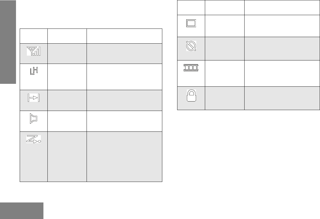
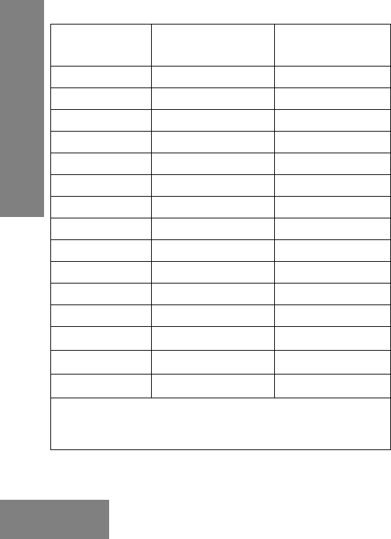
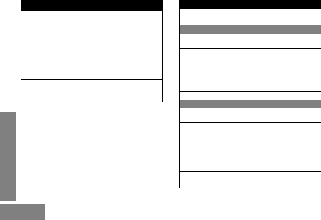
LCD Display and Icons
Displays selected channel, programming parameters, status
messages and any error or information messages.
LCD
Indicator
Description Function
Signal Strength
Indicator
Shows the signal strength. More
bars indicate a stronger signal
received by radio.
Power Level
Indicator
“L” illuminates to indicate radio is
configured to transmit in low
power; “H” illuminates when radio
transmits in high power.
Talkaround
Indicator
Illuminates when radio is not
transmitting through the repeater.
Monitor
Indicator
Illuminates when monitoring a
selected channel.
Scan Indicator Blinks without dot, when normal
scan is activated.
Illuminates without dot, when
there is some activity on a non-
priority channel.
Illuminates with dot blinking, to
indicate that there is some
activity on the priority channel.
LCD
Indicator
Description Function
Programming
Mode Indicator
Illuminates when radio is in
Programming Mode.
Keypad Lock
Indicator
Illuminates when keypad is
locked.
Battery Level
Indicator
Shows remaining charge in
battery based on how many bars
(1 – 3) are displayed. Blinks
when the battery is low.
Voice Inversion
Scrambling
Indicator
Illuminates when scrambling is
on.
5English
RADIO OVERVIEW
English
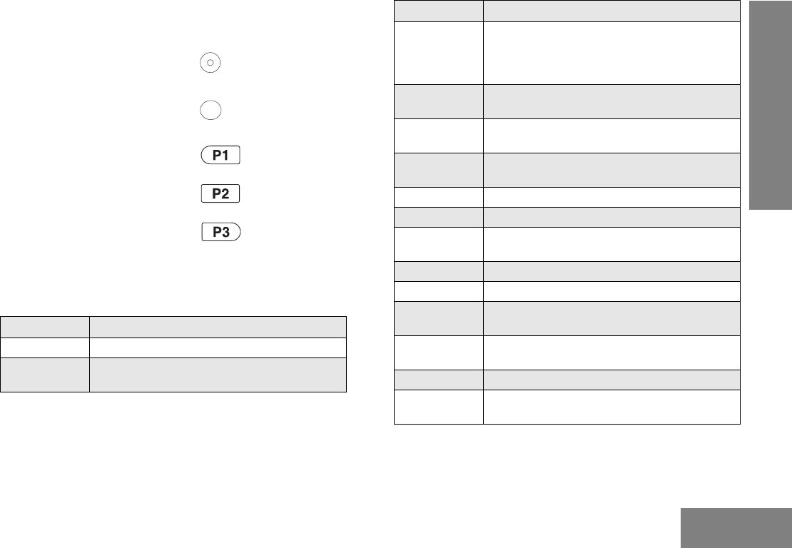
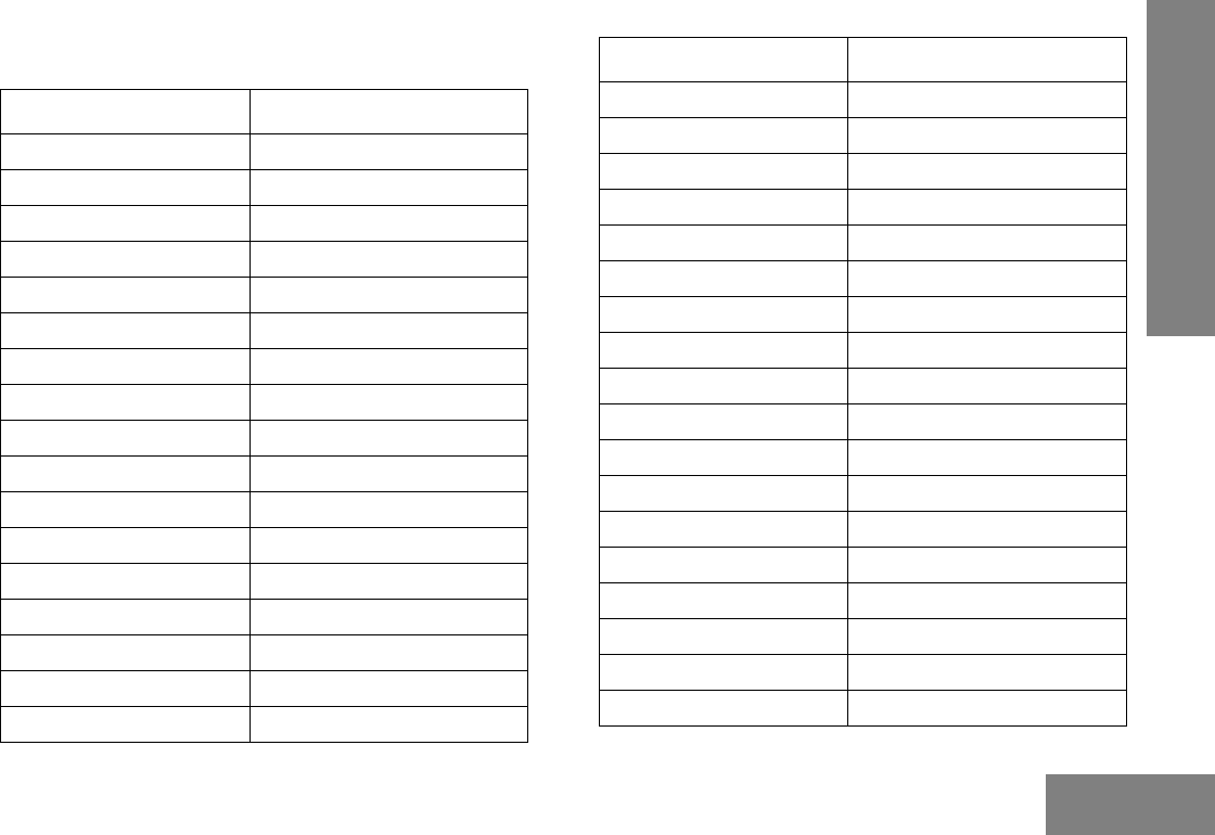
Programmable Buttons
The programmable buttons consist of:
• Side Programmable Button 1
• Side Programmable Button 2
• Front Programmable Button 1
• Front Programmable Button 2
• Front Programmable Button 3
The following functions can be assigned as short press (press
and release) or long press (press and hold for more than 1
second).
Button Function
Backlight Toggles backlight display between ON and OFF.
Channel Alias Toggles display between Channel Number and
Channel Alias.
Button Function
Keypad Lock Locks or unlocks all buttons except PTT, Side
Programmable Button 1, Side Programmable
Button 2, Channel Selector Knob and ON/OFF/
Volume Knob.
Monitor Monitors the channel for any activity as long as
the button is pressed.
Nuisance
Channel Delete
Removes unwanted channel(s) temporarily from
scan list during scan.
TPL/DPL
Enable
Enables or disables radio from requiring
matching TPL/DPL to unsquelch.
Power Level Selects required power level: High or Low.
Prime Channel Quick move to the selected Prime Channel.
Reverse Burst Select the Reverse Burst Type: None, 180 or
240.
Scan Starts or stops channel scan.
Squelch Level Selects desired squelch level: Normal or Tight.
Sticky Monitor Toggles the permanent monitor function until the
button is pressed again.
Talkaround/
Repeater Mode
Allows the user to toggle between repeater and
talkaround mode operations.
Unassigned No function is programmed to this button.
Scrambling
Code Select
Select the scrambling code: 3.29kHz or 3.39kHz
RADIO OVERVIEW
6English
English
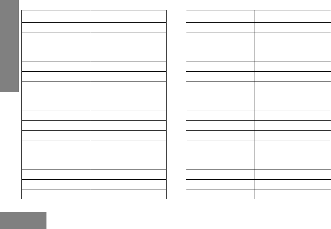
The default functions assigned to your radio are described in
the table below.
If your dealer has re-programmed your radio’s programmable
buttons, you may want to write down the new functions in the
table below.
Button Function
Scrambling
Enable/Disable
Enables or disables scrambling feature for the
selected channel.
Volume Set A programmable button used to control the
audio level. The button emits a
continuous tone to indicate the current
volume level. To change volume level, turn the
volume knob to the desired level while
pressing the programmable button.
VOX Enables or disables VOX feature for the selected
channel.
Press
Type
Side
Button 1
Side
Button 2
Front
Button
1
Front
Button 2
Front
Button 3
Short
Press
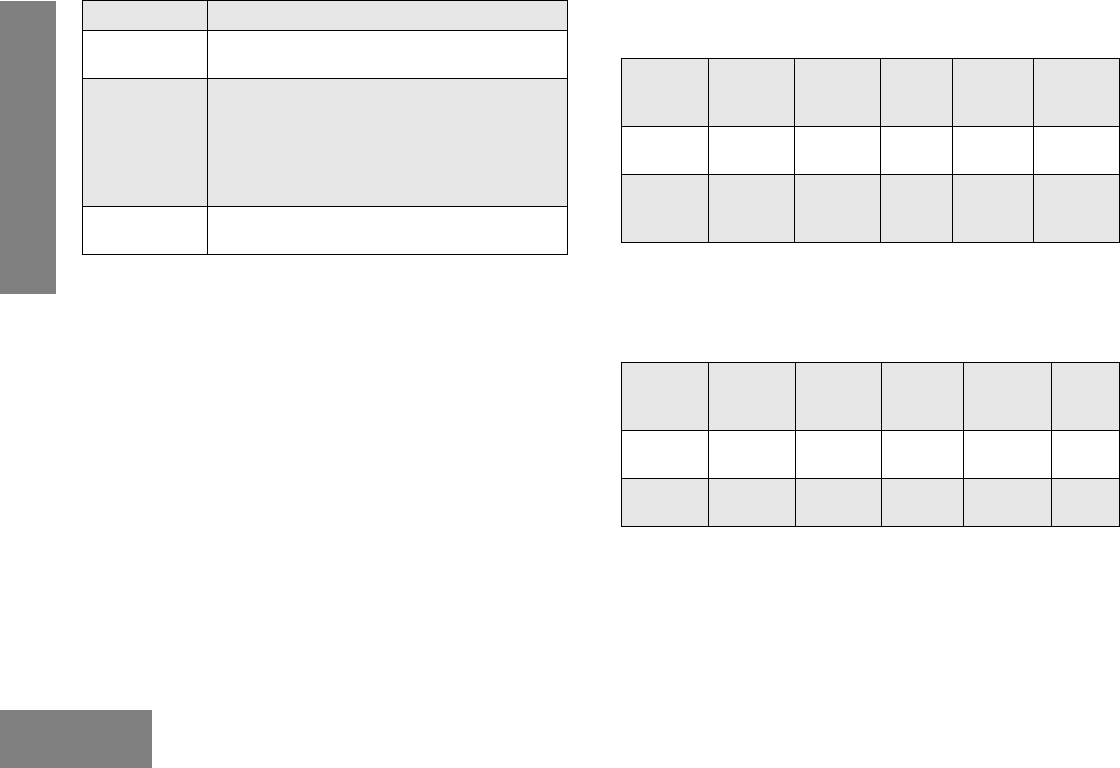
Unassign Unassign Monitor Scan Power
Level
Long
Press
Unassign Unassign Sticky
Monitor
Nuisance
Channel
Delete
Unassign
Press
Type
Side
Button 1
Side
Button 2
Front
Button 1
Front
Button 2
Front
Button
3
Short
Press
Long
Press
7English
GETTING STARTED
GETTING STARTED
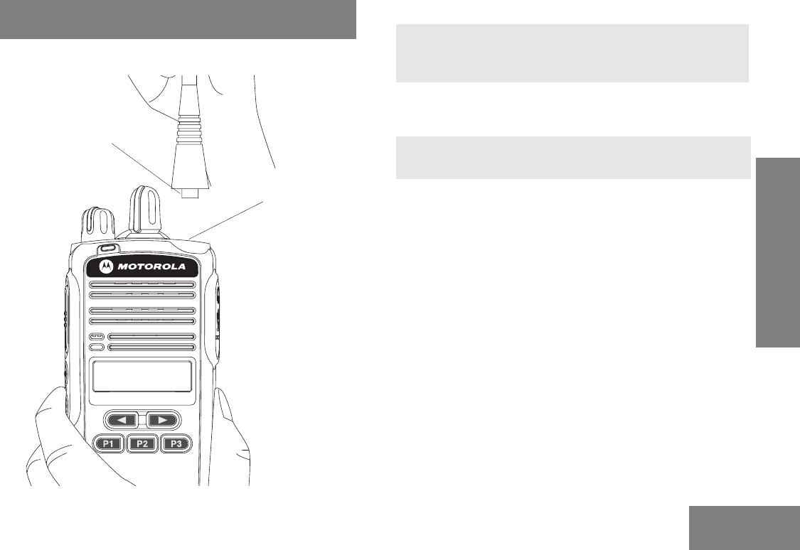
Attaching and Removing the Antenna
To Attach Antenna
To Remove Antenna
CP185
Antenna Connector
Threaded End
of Antenna
1. Fasten the antenna to the radio by placing the
threaded end of the antenna into the Antenna
Connector.
2. Rotate the antenna clockwise until tight.
1. Turn the antenna in a counter-clockwise direction
until it disengages from the radio.
8
English
GETTING STARTED
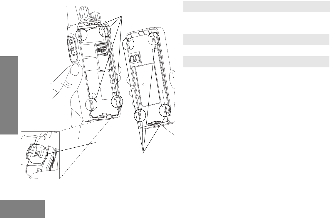
Attaching and Removing the Battery To Attach Battery
To Remove Battery
Battery Slots
Grooves
Battery
Latch
1. Fit the battery slots with the grooves on the radio.
2. Slide the battery upwards until a click is heard.
1. Slide the battery latch away from the radio.
2. Slide the battery downwards.
3. Pull the battery away from the radio.
9English
GETTING STARTED
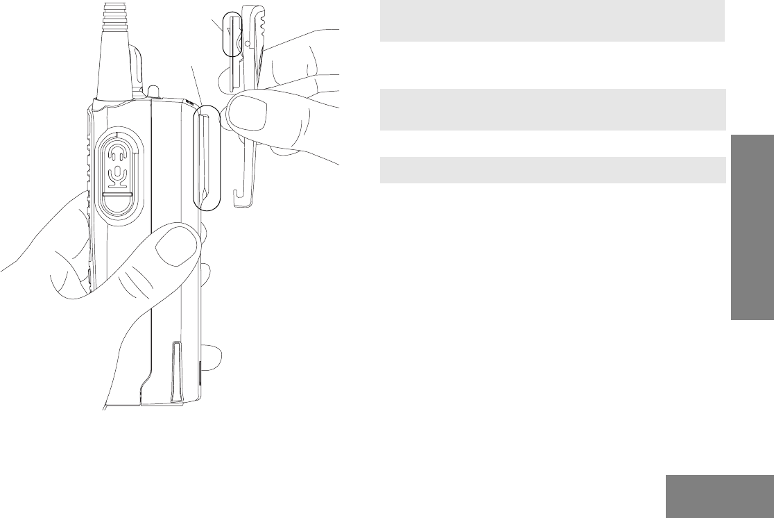
Attaching and Removing the Belt Clip To Attach Belt Clip
To Remove Belt Clip
Release Tab
Mounting Grooves
1. Align mounting rails of the belt clip with the grooves
of the radio.
2. Slide the belt clip downwards until it clicks into place.
1. Safely insert a flat tool between the release tab and
the back surface of the radio.
2. Lift the release tab.
3. Slide the belt clip upwards.
10
English
GETTING STARTED
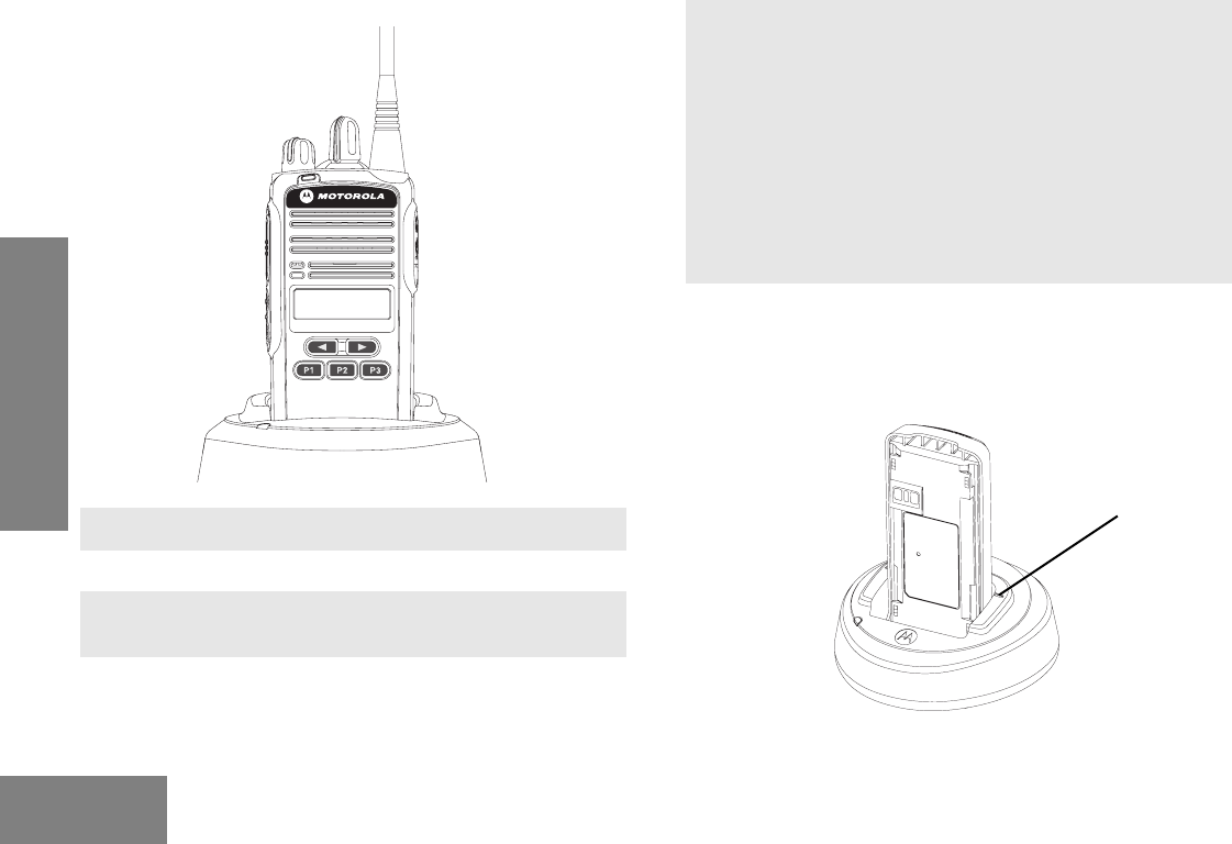
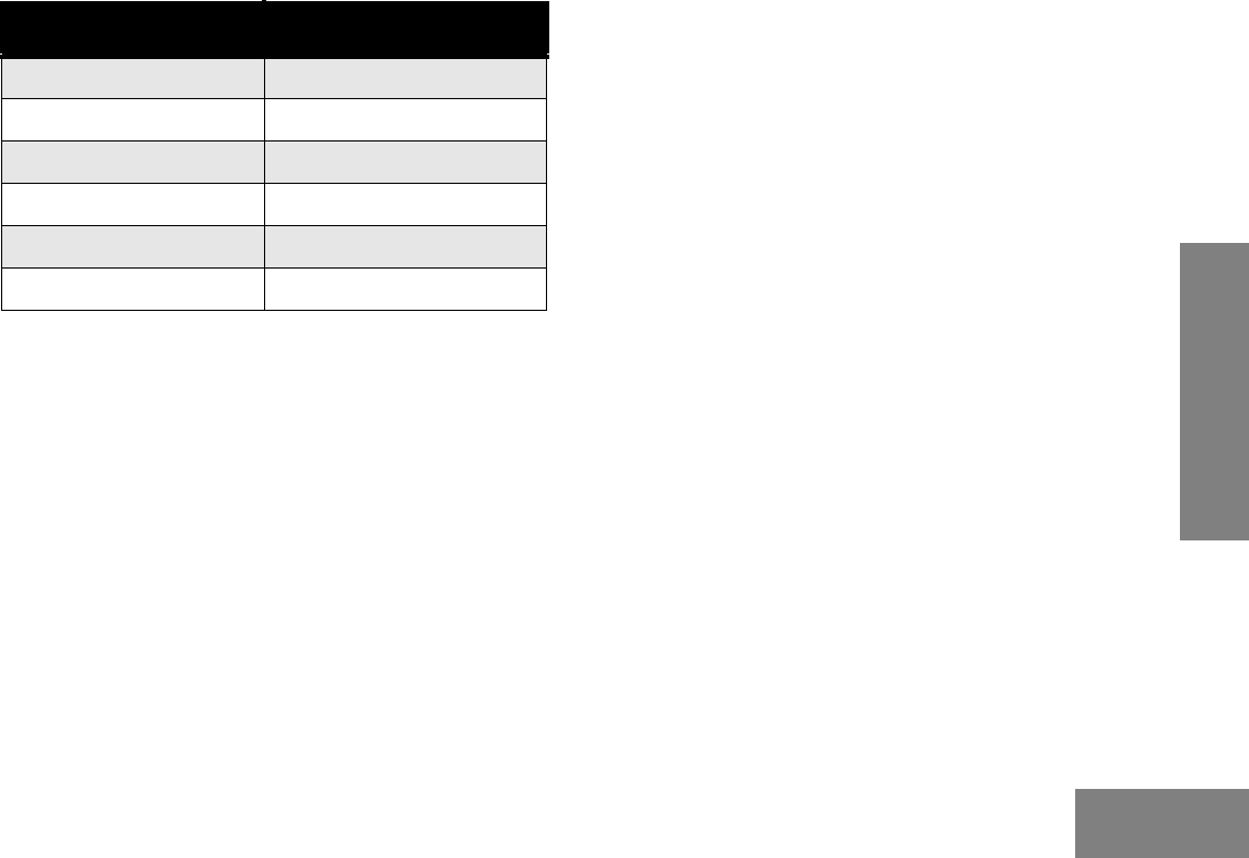
Charging the Battery
Refer to picture below for the battery insert visual guide line.
1. Make sure radio is OFF.
2. Plug the power supply into an electric outlet.
3. Connect the power supply output cord connector into
the rear of the Desktop Changing Tray.,
4. The LED on the charger blinks green once to indicate
charger is turned ON.
CP185
5. Turn the radio OFF before charging the battery.
Insert a battery, or a radio with a battery into the
charger’s pocket by:
a) Aligning the groove on each side of the battery
with the corresponding raised rail on each side of
the charger pocket OR
b) Pressing the battery towards the rear of the
pocket OR
c) Sliding the battery into the charger pocket,
ensuring complete contact between the charger
and battery contacts.
6. The charger’s LED color will indicate the battery
charging status. (See “Charging Status” on page 11).
Battery insert visual guide line
11 English
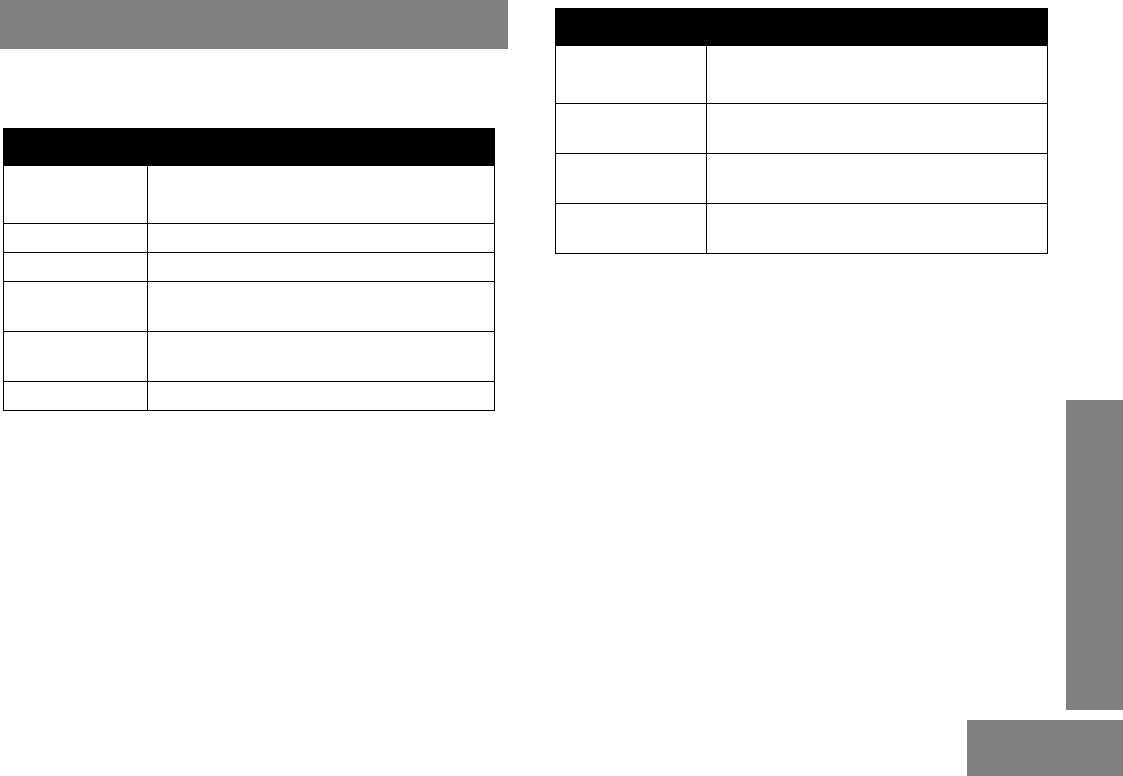
GETTING STARTED
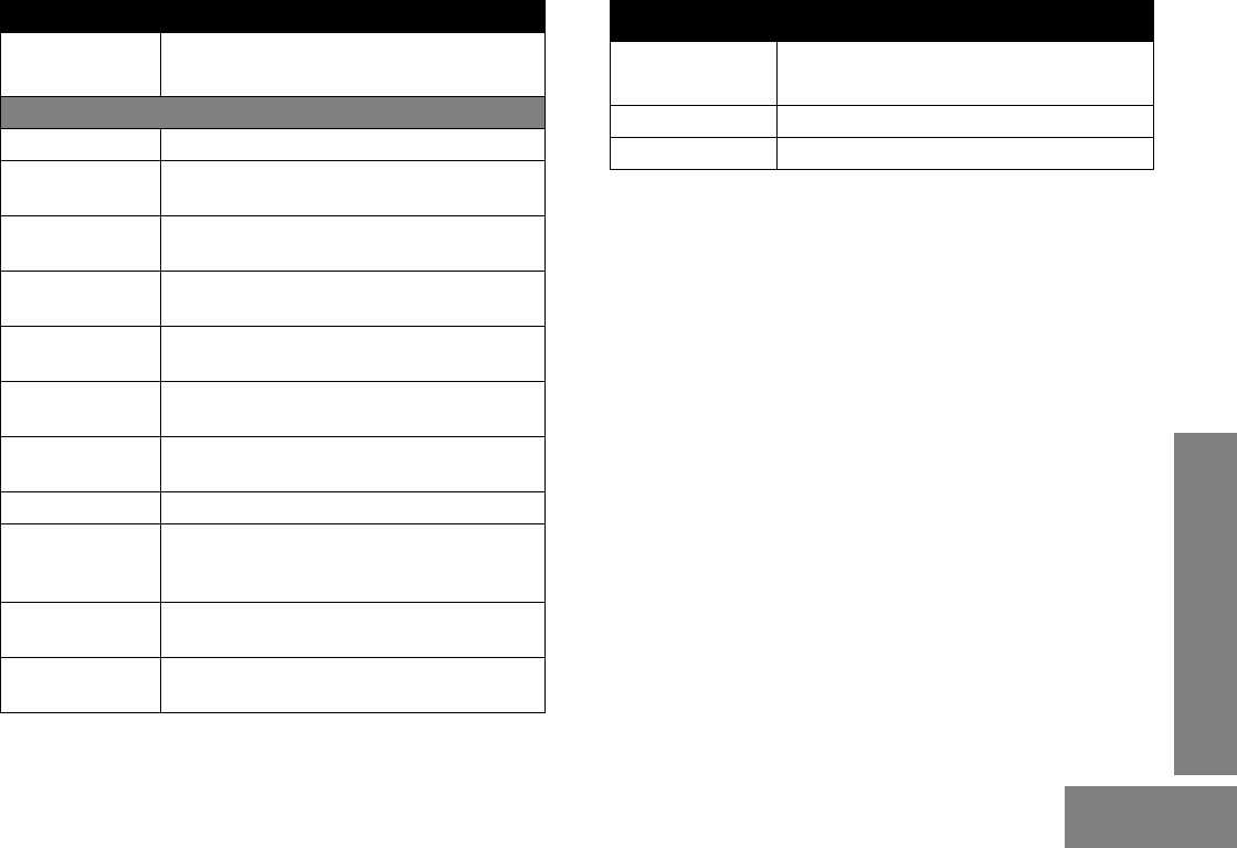
Note: To get maximum use from a new battery, charge it
overnight (12 to 16 hours) before using the battery for the
first time. The typical time needed to completely charge
the discharged battery is estimated within 2.5 to 5 hours
depending on its cell chemistry. Once the charger LED
turns solid green, the charging process is done.
LED Color Charging Status
Solid Red Charging
Blinking Red Battery Fault
Solid Green Charge Complete
Blinking Green Trickle Charging
Single Green Blink Power On
Blinking Yellow Waiting to Charge

12
English
SCAN
SCAN
Scan allows you to monitor multiple channels and receive calls
that are transmitted on them.
Two types of scan are supported: Normal Scan and Priority
Scan. Normal Scan searches all channels sequentially in the
radio’s scan list, whereas Priority Scan allocates 50% of the
scanning time to the Priority Channel (the first channel in the
designated scan list).
During scan, when activity is detected that meets the
unsquelch condition, the radio stops scanning and switches to
that channel; the G indicator is illuminated, and the channel
number is displayed. When no activity is detected for a pre-set
time, the radio resumes scanning.
If your radio has switched to a non-priority channel during
priority scan, it still checks for activity on the priority channel. If
activity is detected there, the radio switches to the priority
channel.
The radio transmits on the Home Channel, if PTT is pressed
during scanning. If the radio stops scanning, and changes to a
particular channel, all transmit and receive activity is
performed on that channel.
• Press the Scan button to begin channel scanning. The G
indicator blinks to indicate that the radio is scanning. The
LCD Screen shows the Home Channel where the scan
began.
• Press Scan button to stop scanning.
Deleting a Nuisance Scan Channel
A channel with unwanted activity is called a Nuisance
Channel. You can remove a Nuisance Channel from the scan
list temporarily. To remove a Nuisance Channel
• Press the Nuisance Channel Delete programmable button,
when your radio stops on a Nuisance Channel. A high-
pitched tone is heard.
You cannot remove the Home or Priority Channel from the
scan list. If attempted, a low-pitched tone is heard, and no
action is taken.
To reinstate the deleted channel(s) into the scan list, restart
scan, or simply turn off your radio and turn it on again.
Ch. 2 Ch. 3 Ch. 4
Ch. 1
Ch. 15
Ch. 14
Ch. 16
Home
Normal Scan
Start
Ch. 2 Ch. 1 Ch. 3
Ch. 1
Ch. 16
Ch. 1
Ch. 1
Home
Start
Priority Scan
Channel 1 Prioritized

13 English
VOICE OPERATED TRANSMIT (VOX)
VOICE OPERATED TRANSMIT (VOX)
When the VOX headset/microphone is connected, your radio
may be used in hands-free operation.
To start the VOX feature:
1. Connect the VOX headset to the accessory connector of
the radio. Make sure the radio is turned OFF before
connecting the VOX accessory.
2. Turn the radio ON.
To disable the VOX feature:
1. Press the PTT button on the radio. This allows you to use
the VOX headset, but you must press the radio PTT to
transmit.
To re-enable the VOX feature:
1. Turn the radio OFF, and turn it ON again, with the headset
connected to the accessory connector, or
2. Change channel with the VOX headset connected.
To adjust the VOX sensitivity level, see “ACCESORY
(Accessory)” on page 17 of this user guide.

14
English
VOICE INVERSION SCRAMBLING
VOICE INVERSION SCRAMBLING
Your radio has the Voice Inversion Scrambling feature which
gives you an extra layer of privacy. This scrambling function is
implemented via a frequency inversion in analog mode using
two standard codes (3.29 KHz and 3.39 KHz).
To Enable and Disable the Scrambling Mode
Configure one of the programmable buttons for Scrambling
Mode. Press this button to enable or disable the function. You
can also configure this function via the Front Panel
Programming Mode ("Front Panel Programming Mode" Menu
on page 15).
To Change the Scrambling Code
Configure one of the programmable buttons for Scrambling
Code. Press this button to toggle between the two codes. You
can also configure this function via the Front Panel
Programming Mode ("Front Panel Programming Mode" Menu
on page 15).

15
FRONT PANEL
PROGRAMMING MODE
English
FRONT PANEL PROGRAMMING
MODE
This mode allows you to change the feature parameters to
enhance the use of your radio.
Note: This feature is only supported by certain models.
Entering Front Panel Programming Mode
If your radio is turned ON, turn it OFF. Press and hold the side
programmable button 1, and turn your radio ON. A tone is
heard, indicating that your radio is in Programming Mode. The
indicator illuminates and the “BCKLIGHT” is displayed on
the radio LCD.
Exiting Front Panel Programming Mode
Turn the radio OFF to exit Programming Mode.
Assessing Front Panel Programming Mode
Parameters
Press the or to scroll through the parameters
for each menu or sub-menu item, or
Press the PTT button to select menu or sub-menu item, or
Press side programmable button 1 to return to previous menu
level or to exit the selection parameter without change.

16
FRONT PANEL
PROGRAMMING MODE
English
Main Menu 1st Level
Sub-Menu
2nd Level
Sub-Menu Setting Remarks
BCKLIGHT
(Backlight)
AUTO
TOGGLE
Selecting AUTO causes the backlight to automatically
extinguish, if there is no keypress for more than 5 seconds.
Pressing the Backlight button again prolongs illumination
time.
Selecting TOGGLE allows the Backlight button
toggle to control the ON/OFF status of the backlight.
BATTERY SAVER
(Battery Saver)
OFF
NORMAL
ENHANCED
Helps to extend the battery life. When enabled, it turns off
radio receiver circuitry periodically when no activity is
detected.
NORMAL – turns off the receiver less frequently.
ENHANCED – turns off the receiver for a longer duration to
maximize battery saving.
TYPE
(Battery Type)
NIMH (Nickel Metal
Hydride)
LI-ION (Lithium-Ion)
H LI-ION (High
Capacity
Lithium- Ion)
Selects the type of battery that the radio uses.

17
FRONT PANEL
PROGRAMMING MODE
English
Main Menu 1st Level
Sub-Menu
2nd Level
Sub-Menu Setting Remarks
ACCESORY
(Accessory)
SPK GAIN
(External Speaker
Gain)
+2
+1
0
-1
-2
Allows you to adjust the external
speaker loudness when accessories
are connected to radio. +2 will set the
external speaker gain to maximum level
and -2 will set the external speaker gain
to minimum level.
MIC GAIN
(External
Microphone Gain)
+2
+1
0
-1
-2
Allows you to adjust the external
microphone sensitivity when
accessories are connected to radio.
+2 will set the external microphone
sensitivity to maximum level and -2 will
set the external microphone sensitivity
to minimum level.
TONE VOL
(Alert Tone Volume)
ON
OFF
Selects the alert tone volume
preference.
Select OFF, if quiet operation is
required.
Select ON, if working in a noisy
environment.

18
FRONT PANEL
PROGRAMMING MODE
English
Main
Menu
1st Level
Sub-Menu
2nd Level
Sub-Menu
Settings Remarks
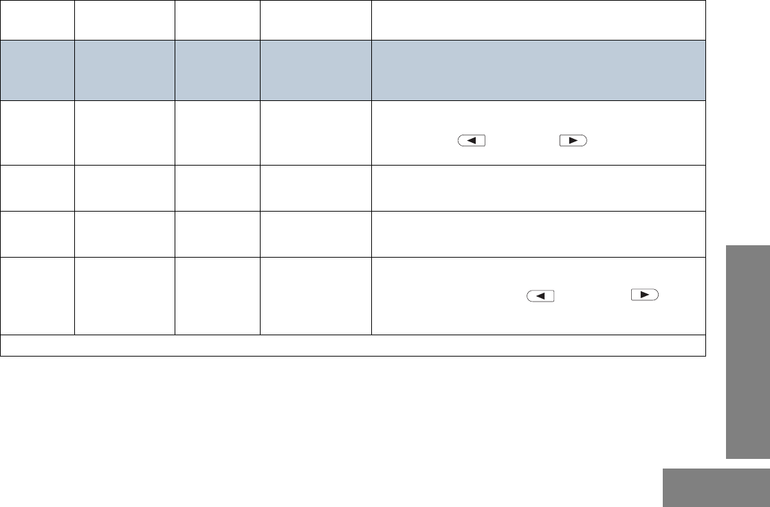
CHANNEL RX PL
(Receive TPL/
DPL)
CH-001
…
CH-099
CSQ (Carrier
Squelch)
TPL 067.0…
TPL 254.1
TPL1
TPL2
TPL3
DPL 023…
DPL 754
This is the TPL or DPL code that the channel will use to
unsquelch the received signal. CSQ indicates that radio operates
in carrier squelch mode. Press Left Arrow Button or Right Arrow
Button to select the desired TPL/DPL.
TX PL
(Transmit TPL/
DPL)
CH-001
…
CH-099
CSQ (Carrier
Squelch)
TPL 067.0…
TPL 254.1
DPL 023…
DPL 754
TPL1
TPL2
TPL3
This is the TPL or DPL code that the channel will use to transmit.
CSQ indicates that radio operates in carrier squelch mode. Press
Left Arrow Button or Right Arrow Button to select the desired TPL/
DPL.
SQUELCH
(Squelch Level)
CH-001...
CH-099
NORMAL
TIGHT
NORMAL squelch level allows the radio to receive weak signals. TIGHT
squelch level allows the radio to receive strong signals and eliminates
unwanted noise.
TIME OUT (Time
Out Timer)
OFF
010
020
...
590
600
This determines the maximum duration (in seconds) that the radio can
transmit continuously.
19
FRONT PANEL
PROGRAMMING MODE
English
Main
Menu
1st Level
Sub-Menu
2nd Level
Sub-Menu
Settings Remarks
CHANNEL
(Cont’d)
PRIME CH (Prime
Channel)
OFF
001...
099
The channel that you wish to spend most of your time monitoring. The
radio will always switch back to the Prime Channel if it is idle for more
than the preprogrammed hang-time in other channels.
.
SCAN LIST 1
(Scan List 1)
01-XXX
02-XXX
…
15-XXX
16-XXX
_ _ _
001
…
099
Allows you to set scan list 1 members. “XXX “denotes the selected scan
list member. "_ _ _" shows that no scan list member is selected.
User can use the button or the button to scroll the
valid channel list and press PTT to set the selection.
LIST SEL
(Scan List Select)
CH-001
…
CH-099
LIST1 (Scan List 1) Allows you to set the scan list for a selected channel.
SCAN TYP
(Scan Type
Select)
CH-001
…
CH-099
NORMAL
PRIORITY
Allows you to set scan type either Normal Scan or Priority Scan for a
selected channel.
PRIORITY
(Priority Channel
Select)
LIST1
(Scan List 1)
_ _ _
...
XXX
Allows you to set priority channel for scan list 1. XXX denotes the
selected priority channel. "_ _ _" shows that no priority channel is
selected. User can also use the button or the
button to scroll the valid channel list and press PTT to set the
selection.
(*) Applicable to Keypad Models only.

20
FRONT PANEL
PROGRAMMING MODE
English
Notes:
21
TPL AND DPL FREQUENCIES
AND CODES
English
TPL AND DPL FREQUENCIES AND
CODES
The following information in the tables are to guide the user to
select the appropriate TPL (Tone Private Line) or DPL (Digital
Private Line) codes so that they can expand usage of the
frequency.
TPL Frequency
Table 1: TPL Frequency
TPL Freq (Hz) Equivalent PL
Code Motorola Code
67.0 XZ 001
69.3 WZ 002
71.9 XA 003
74.4 WA 004
77.0 XB 005
79.7 WB 006
82.5 YZ 007
85.4 YA 008
88.5 YB 009
91.5 ZZ 010
94.8 ZA 011
97.4 ZB 012
100.0 1Z 013
103.5 1A 014
107.2 1B 015
110.9 2Z 016
114.8 2A 017
118.8 2B 018
123.0 3Z 019
127.3 3A 020
131.8 3B 021
136.5 4Z 022
141.3 4A 023
146.2 4B 024
151.4 5Z 025
156.7 5A 026
162.2 5B 027
167.9 6Z 028
173.8 6A 029
179.9 6B 030
Table 1: TPL Frequency
TPL Freq (Hz) Equivalent PL
Code Motorola Code
22
TPL AND DPL FREQUENCIES
AND CODES
English
186.2 7Z 031
192.8 7A 032
203.5 M1 033
206.5 8Z 034
210.7 M2 035
218.1 M3 036
225.7 M4 037
229.1 9Z 038
233.6* M5 039
241.8 M6 040
250.3 M7 041
254.1* 0Z 042
TPL1* –TPL1
TPL2* –TPL2
TPL 3* –TPL3
Note: The TPL Frequencies marked with an asterisk (*) are
not part of the 39 standard EIA/TIA-603 CTCSS Code
Frequency.
Table 1: TPL Frequency
TPL Freq (Hz) Equivalent PL
Code Motorola Code
23
TPL AND DPL FREQUENCIES
AND CODES
English
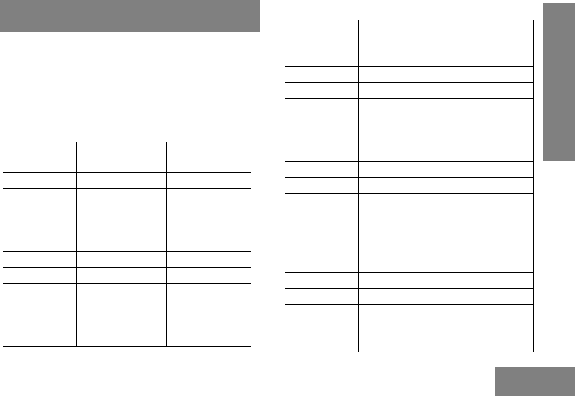
DPL Codes
Table 2: DPL Codes
DPL Code Motorola Code
023 043
025 044
026 045
031 046
032 047
043 048
047 049
051 050
054 051
065 052
071 053
072 054
073 055
074 056
114 057
115 058
116 059
125 060
131 061
132 062
134 063
143 064
152 065
155 066
156 067
162 068
165 069
172 070
174 071
205 072
223 073
226 074
243 075
244 076
245 077
Table 2: DPL Codes
DPL Code Motorola Code
24
TPL AND DPL FREQUENCIES
AND CODES
English
251 078
261 079
263 080
265 081
271 082
306 083
311 084
315 085
331 086
343 087
346 088
351 089
364 090
365 091
371 092
411 093
412 094
413 095
Table 2: DPL Codes
DPL Code Motorola Code
423 096
431 097
432 098
445 099
464 100
465 101
466 102
503 103
506 104
516 105
525(*) 106
532 107
546 108
565 109
606 110
612 111
624 112
627 113
Table 2: DPL Codes
DPL Code Motorola Code

25
TPL AND DPL FREQUENCIES
AND CODES
English
631 114
632 115
645(*) 116
654 117
662 118
664 119
703 120
712 121
723 122
731 123
732 124
734 125
743 126
754 127
Note: The codes marked with an asterisk (*) are not part
of the 83 standard EIA/TIA-603 codes.
Table 2: DPL Codes
DPL Code Motorola Code

26
WARRANTY
English
MOTOROLA LIMITED WARRANTY FOR
THE UNITED STATES AND CANADA
What Does this Warranty Cover?
Subject to the exclusions contained below, Motorola,
Inc. warrants its telephones, pagers, and consumer
and business two-way radios (excluding commercial,
government or industrial radios) that operate via
Family Radio Service or General Mobile Radio
Service, Motorola-branded or certified accessories
sold for use with these Products (“Accessories”) and
Motorola software contained on CD-ROMs or other
tangible media and sold for use with these Products
(“Software”) to be free from defects in materials and
workmanship under normal consumer usage for the
period(s) outlined below.
This limited warranty is a consumer's exclusive
remedy, and applies as follows to new Motorola
Products, Accessories and Software purchased by
consumers in the United States, which are
accompanied by this written warranty.
Products and Accessories
Products
Covered Length of Coverage
Products and
Accessories as defined
above, unless otherwise
provided for below.
One (1) year from the date of
purchase by the first consumer
purchaser of the product unless
otherwise provided for below.
Decorative Accessories
and Cases.
Decorative covers,
bezels, PhoneWrap™
covers and cases.
Limited lifetime warranty for the
lifetime of ownership by the first
consumer purchaser of the
product.
Business Two-way
Radio Accessories
One (1) year from the date of
purchase by the first consumer
purchaser of the product.
Products and
Accessories that are
Repaired or Replaced.
The balance of the original
warranty or for ninety (90) days
from the date returned to the
consumer, whichever is longer.

27
WARRANTY
English
Exclusions
Normal Wear and Tear. Periodic maintenance, repair
and replacement of parts due to normal wear and tear
are excluded from coverage.
Batteries. Only batteries whose fully charged capacity
falls below 80% of their rated capacity and batteries
that leak are covered by this limited warranty.
Abuse & Misuse. Defects or damage that result from:
(a) improper operation, storage, misuse or abuse,
accident or neglect, such as physical damage (cracks,
scratches, etc.) to the surface of the product resulting
from misuse; (b) contact with liquid, water, rain,
extreme humidity or heavy perspiration, sand, dirt or
the like, extreme heat, or food; (c) use of the Products
or Accessories for commercial purposes or subjecting
the Product or Accessory to abnormal usage or
conditions; or (d) other acts which are not the fault of
Motorola, are excluded from coverage.
Use of Non-Motorola Products and Accessories.
Defects or damage that result from the use of Non-
Motorola branded or certified Products, Accessories,
Software or other peripheral equipment are excluded
from coverage.
Unauthorized Service or Modification. Defects or
damages resulting from service, testing, adjustment,
installation, maintenance, alteration, or modification in
any way by someone other than Motorola, or its
authorized service centers, are excluded from
coverage.
Altered Products. Products or Accessories with (a)
serial numbers or date tags that have been removed,
altered or obliterated; (b) broken seals or that show
evidence of tampering; (c) mismatched board serial
numbers; or (d) nonconforming or non-Motorola
housings, or parts, are excluded form coverage.

28
WARRANTY
English
Communication Services. Defects, damages, or the
failure of Products, Accessories or Software due to any
communication service or signal you may subscribe to
or use with the Products Accessories or Software is
excluded from coverage.
Software
Exclusions
Software Embodied in Physical Media. No warranty
is made that the software will meet your requirements
or will work in combination with any hardware or
software applications provided by third parties, that the
operation of the software products will be
uninterrupted or error free, or that all defects in the
software products will be corrected.
Software NOT Embodied in Physical Media.
Software that is not embodied in physical media (e.g.
software that is downloaded from the internet), is
provided “as is” and without warranty.
WHO IS COVERED?
This warranty extends only to the first consumer
purchaser, and is not transferable.
HOW TO OBTAIN WARRANTY SERVICE OR
OTHER INFORMATION?
Contact your Motorola point of purchase.
Products Covered Length of Coverage
Software. Applies
only to physical
defects in the media
that embodies the
copy of the software
(e.g. CD-ROM, or
floppy disk).
Ninety (90) days from
the date of purchase.

29
WARRANTY
English
SOFTWARE COPYRIGHT NOTICE
The Motorola products described in this manual may
include copyrighted Motorola and third party software
stored in semiconductor memories or other media.
Laws in the United States and other countries preserve
for Motorola and third party software providers certain
exclusive rights for copyrighted software, such as the
exclusive rights to distribute or reproduce the
copyrighted software. Accordingly, any copyrighted
software contained in the Motorola products may not
be modified, reverse-engineered, distributed, or
reproduced in any manner to the extent allowed by
law.
Furthermore, the purchase of the Motorola products
shall not be deemed to grant either directly or by
implication, estoppel, or otherwise, any license under
the copyrights, patents, or patent applications of
Motorola or any third party software provider, except
for the normal, non-exclusive, royalty-free license to
use that arises by operation of law in the sale of a
product.
PATENT NOTICE
This product is covered by one or more of the following
United States patents.
5896277 5894292 5864752 5699006 5742484
D408396 D399821 D387758 D389158 5894592
5893027 5789098 5734975 5861850 D395882
D383745 D389827 D389139 5929825 5926514
5953640 6071640 D413022 D416252 D416893
D433001
EXPORT LAW ASSURANCES
This product is controlled under the export regulations
of the United States of America. The Governments of
the United States of America may restrict the
exportation or re-exportation of this product to certain
destinations. For further information contact the U.S.
Department of Commerce.

30
WARRANTY
English
Notes:
31
ACCESSORIES
English
ACCESSORIES
The following accessories parts are compatible with model
number CP185.
ANTENNAS
Motorola Part
Number Description
NAD6502_R VHF Heliflex Antenna, 146 – 174 Mhz
PMAD4049_ VHF Helical Antenna, 146 – 174 MHz
NAE6483_R UHF Whip Antenna, 403 – 520 MHz
(16.5 cm)
NAE6522_R UHF Stubby Antenna, 438 – 470 MHz
(7.5 cm)
PMAE4016_ UHF Whip Antenna, 403 – 520 MHz
BATTERIES
Motorola Part
Number Description
PMNN4080_ Li-Ion High Capacity – 2150mAh: 14hrs
talktime @ 5-5-90 at High Power
PMNN4081_ Li-Ion – 1500mAh: 10hrs talktime @
5-5-90 at High Power
PMNN4082_ NiMH – 1300mAh: 8hrs talktime @
5-5-90 at High Power
32
ACCESSORIES
English
CHARGERS AND POWER ADAPTERS
Motorola Part
Number Description
PMLN5228_ Tri-Chem Single Unit Charger Base
PMLN5398_ Single Unit Charger Base with US 2-Pin
Switch Mode Power Supply
2571586S14 110V, 10.8W Linear Power Supply with
North America / Latin America country
plug
EPNN9288_ 90 – 264V, Switch Mode Power Supply
with North America /Latin America country
plug
AUDIO ACCESSORIES
Motorola Part
Number Description
MAG ONE™ Branded
PMLN4442_ Earbud with In-Line Microphone / PTT /
VOX Switch (MagOne)
PMLN4443_ Ear Receiver with In-Line Microphone /
PTT / VOX Switch (MagOne)
PMLN4444_ Earset with Boom Microphone and In-Line
PTT/VOX Switch (MagOne)
PMLN4445_ Ultra-Light Headset with Boom Microphone
and In-Line PTT/VOX Switch (MagOne)
PMMN4008_ Remote Speaker Microphone (MagOne)
MOTOROLA Branded
HMN9013_ Lightweight Single Muff Adjustable
Headset with Swivel Boom Microphone
HMN9754_ 2-Piece Surveillance Kit, with Microphone
and PTT Combined, Beige (2-wire –
Rubber Eartip Style)
PMLN4606_ 2-wire earpiece with clear acoustic tube
(consisting of PMLN4605 & PMLN4294)
PMLN4620_ Receive Only D-Style Earpiece (for
PMMN4013 Remote Speaker Microphone)
PMLN5001_ D-Style Earpiece with Microphone / PTT
PMLN5003_ Retail Temple Transducer Headset
33
ACCESSORIES
English
Note: Certain accessories may be or may not be available at the
time of purchase. For latest information on accessories,
contact your Motorola point of purchase or visit:
http://www.motorola.com/governmentandenterprise.
AUDIO ACCESSORIES
Motorola Part
Number Description
MOTOROLA Branded
PMMN4001_ Earset with Microphone and PTT
PMMN4013_ Remote Speaker Microphone with Ear
Jack
PMMN4029_ Remote Speaker Microphone with IP57
Rating
RLN6230_ High Noise Kit, Black (Includes Foam
Earplugs with Acoustic Tube)
RLN6231_ High Noise Kit, Beige (Includes Foam
Earplugs with Acoustic Tube)
RLN6232_ Low Noise Kit, Black (Includes Rubber Tip
with Acoustic Tube)
RLN6241_ Low Noise Kit, Beige (Includes Rubber Tip
with Acoustic Tube)
RLN6242_ Quick Disconnect Acoustic Tube
RLN4941_ Receive Only Earpiece with Translucent
Tube (for PMMN4013 Remote Speaker
Microphone)
WADN4190_ Receive Only Flexible Earpiece (for
PMMN4013 Remote Speaker Microphone)
AARLN4885_ Receive Only Earbud (for PMMN4013
Remote Speaker Microphone)
MISCELLANEOUS
Motorola Part
Number Description
HLN9844_ Spring Action Belt Clip (2 inch)
PMLN5334_ Protective Leather Case

34
ACCESSORIES
English
Notes:

MOTOROLA and the Stylized M Logo are registered in the US Patent & Trademark Office.
All other product or service names are the property of their respective owners.
© 2008 by Motorola, Inc.
All rights reserved.
*6878080A01*
6878080A01-A