Motorola Solutions 89FT4884 PORTABLE 2-WAY RADIO User Manual
Motorola Solutions, Inc. PORTABLE 2-WAY RADIO
USERS MANUAL
Declaration of Conformity
English
i
Declaration of Conformity
This declaration is applicable to your radio only if your radio is labeled with the FCC logo shown below.
DECLARATION OF CONFORMITY
Per FCC CFR 47 Part 2 Section 2.1077(a)
Responsible Party
Name: Motorola, Inc.
Address: 1301 East Algonquin Road, Schaumburg, IL 60196-1078, U.S.A.
Phone Number: 1-888-567-7347
Hereby declares that the product:
Model Name: XPR 6300/XPR 6350
conforms to the following regulations:
FCC Part 15, subpart B, section 15.107(a), 15.107(d) and section 15.109(a)
Class B Digital Device
As a personal computer peripheral, this device complies with Part 15 of the FCC Rules. Operation is subject to the
following two conditions:
1. This device may not cause harmful interference, and
2. This device must accept any interference received, including interference that may cause undesired operation.

Declaration of Conformity
English
ii
Note: This equipment has been tested and found to comply with the limits for a Class B digital device, pursuant to part
15 of the FCC Rules. These limits are designed to provide reasonable protection against harmful interference in a
residential installation. This equipment generates, uses and can radiate radio frequency energy and, if not
installed and used in accordance with the instructions, may cause harmful interference to radio communications.
However, there is no guarantee that interference will not occur in a particular installation.
If this equipment does cause harmful interference to radio or television reception, which can be determined by
turning the equipment off and on, the user is encouraged to try to correct the interference by one or more of the
following measures:
•Reorient or relocate the receiving antenna.
•Increase the separation between the equipment and receiver.
•Connect the equipment into an outlet on a circuit different from that to which the receiver is connected.
•Consult the dealer or an experienced radio/TV technician for help.

Contents
English
iii
Contents
This User Guide contains all the information you need to
use the MOTOTRBO XPR Series Digital Portable Radios.
Declaration of Conformity . . . . . . . . . . . . . . . . . . . . . i
Important Safety Information . . . . . . . . . . . . . . . . . . v
Product Safety and RF Exposure Compliance . . . v
Software Version . . . . . . . . . . . . . . . . . . . . . . . . . . . . v
Computer Software Copyrights . . . . . . . . . . . . . . . vi
Getting Started . . . . . . . . . . . . . . . . . . . . . . . . . . . . . . 1
How to Use This Guide . . . . . . . . . . . . . . . . . . . . . . . 1
What Your Dealer/System Administrator
Can Tell You . . . . . . . . . . . . . . . . . . . . . . . . . . . . . . 1
Preparing Your Radio for Use . . . . . . . . . . . . . . . . . . 2
Charging the Battery . . . . . . . . . . . . . . . . . . . . . . . . . 2
Attaching the Battery . . . . . . . . . . . . . . . . . . . . . . . . . 2
Attaching the Antenna . . . . . . . . . . . . . . . . . . . . . . . . 3
Attaching the Belt Clip . . . . . . . . . . . . . . . . . . . . . . . . 3
Attaching the Universal Connector Cover . . . . . . . . . 3
Powering Up the Radio . . . . . . . . . . . . . . . . . . . . . . . 4
Adjusting the Volume . . . . . . . . . . . . . . . . . . . . . . . . 4
Identifying Radio Controls . . . . . . . . . . . . . . . . . . . . 5
Radio Controls You Will Be Using . . . . . . . . . . . . . . 5
Programmable Buttons . . . . . . . . . . . . . . . . . . . . . . . 6
Assignable Radio Functions . . . . . . . . . . . . . . . . . 6
Assignable Settings or Utility Functions . . . . . . . . . 6
Push-To-Talk (PTT) Button . . . . . . . . . . . . . . . . . . . . 7
Switching Between Analog and Digital Mode . . . . . . 7
Identifying Status Indicators . . . . . . . . . . . . . . . . . . . 8
LED Indicator . . . . . . . . . . . . . . . . . . . . . . . . . . . . . . 8
Audio Tones . . . . . . . . . . . . . . . . . . . . . . . . . . . . . . . 8
Indicator Tones . . . . . . . . . . . . . . . . . . . . . . . . . . . . . 9
Receiving and Making Calls . . . . . . . . . . . . . . . . . . . 9
Selecting a Zone . . . . . . . . . . . . . . . . . . . . . . . . . . . . 9
Selecting a Radio Channel, Subscriber ID,
or Group ID . . . . . . . . . . . . . . . . . . . . . . . . . . . . . . 10
Receiving and Responding to a Radio Call . . . . . . 10
Receiving and Responding to a Group Call . . . . . 11
Receiving and Responding to a Private Call . . . . 11
Receiving an All Call . . . . . . . . . . . . . . . . . . . . . . 12
Making a Radio Call . . . . . . . . . . . . . . . . . . . . . . . . 12
Making a Call with the Channel Selector Knob. . . 12
Making a Group Call . . . . . . . . . . . . . . . . . . . . . 12
Making a Private Call . . . . . . . . . . . . . . . . . . . . 13
Making an All Call . . . . . . . . . . . . . . . . . . . . . . . 13
Making a Group or Private Call with the
One Touch Call Button . . . . . . . . . . . . . . . . . . . . 14
Talkaround . . . . . . . . . . . . . . . . . . . . . . . . . . . . . . . 14

Contents
English
iv
Monitoring Features . . . . . . . . . . . . . . . . . . . . . . . . 15
Monitoring a Channel . . . . . . . . . . . . . . . . . . . . . 15
Permanent Monitor . . . . . . . . . . . . . . . . . . . . . . . 15
Advanced Features . . . . . . . . . . . . . . . . . . . . . . . . . 16
Scan Lists . . . . . . . . . . . . . . . . . . . . . . . . . . . . . . . . 16
Scan . . . . . . . . . . . . . . . . . . . . . . . . . . . . . . . . . . . . 16
Starting and Stopping Scan . . . . . . . . . . . . . . . . 17
Responding to a Transmission During
a Scan . . . . . . . . . . . . . . . . . . . . . . . . . . . . . . . . . 17
Deleting a Nuisance Channel . . . . . . . . . . . . . . . 17
Restoring a Nuisance Channel . . . . . . . . . . . . . . 18
Call Indicator Settings . . . . . . . . . . . . . . . . . . . . . . 18
Escalating Alarm Tone Volume . . . . . . . . . . . . . . 18
Call Alert Operation . . . . . . . . . . . . . . . . . . . . . . . . 18
Receiving and Acknowledging a Call Alert . . . . . 18
Making a Call Alert with the One
Touch Call Button . . . . . . . . . . . . . . . . . . . . . . . . 18
Emergency Operation . . . . . . . . . . . . . . . . . . . . . . 19
Sending an Emergency Alarm . . . . . . . . . . . . . . 19
Sending an Emergency Alarm with Call . . . . . . . 20
Sending an Emergency Alarm with Voice
to Follow . . . . . . . . . . . . . . . . . . . . . . . . . . . . . . . 20
Reinitiating an Emergency Mode . . . . . . . . . . . . 21
Exiting an Emergency Mode . . . . . . . . . . . . . . . . 21
Text Messaging Features . . . . . . . . . . . . . . . . . . . . 22
Sending a Quick Text Message . . . . . . . . . . . . . 22
Privacy . . . . . . . . . . . . . . . . . . . . . . . . . . . . . . . . . . 22
Utilities . . . . . . . . . . . . . . . . . . . . . . . . . . . . . . . . . . 23
Setting the Squelch Level . . . . . . . . . . . . . . . . . . 23
Setting the Power Level . . . . . . . . . . . . . . . . . . . 23
Turning the Option Board Feature(s)
On or Off . . . . . . . . . . . . . . . . . . . . . . . . . . . . . . . 24
Turning Radio Tones/Alerts On or Off . . . . . . . . 24
Checking the Battery Strength . . . . . . . . . . . . . . 24
Accessories . . . . . . . . . . . . . . . . . . . . . . . . . . . . . . . 25
Antennas . . . . . . . . . . . . . . . . . . . . . . . . . . . . . . . . 25
Batteries . . . . . . . . . . . . . . . . . . . . . . . . . . . . . . . . . 26
Carry Devices . . . . . . . . . . . . . . . . . . . . . . . . . . . . . 26
Chargers . . . . . . . . . . . . . . . . . . . . . . . . . . . . . . . . 27
Earbuds and Earpieces . . . . . . . . . . . . . . . . . . . . . 27
Headsets and Headset Accessories . . . . . . . . . . . 27
Remote Speaker Microphones . . . . . . . . . . . . . . . . 28
Surveillance Accessories . . . . . . . . . . . . . . . . . . . . 28
Miscellaneous Accessories . . . . . . . . . . . . . . . . . . 29
Notes . . . . . . . . . . . . . . . . . . . . . . . . . . . . . . . . . . . . 30
Batteries and Chargers Warranty . . . . . . . . . . . . . 31
Limited Warranty . . . . . . . . . . . . . . . . . . . . . . . . . . . 32

Important Safety Information
English
v
Important Safety Information
Product Safety and RF Exposure Compliance
ATTENTION!
This radio is restricted to occupational use only to
satisfy FCC RF energy exposure requirements.
Before using this product, read the RF energy awareness
information and operating instructions in the Product
Safety and RF Exposure booklet enclosed with your radio
(Motorola Publication part number 6881095C98) to
ensure compliance with RF energy exposure limits.
For a list of Motorola-approved antennas, batteries, and
other accessories, visit the following website:
http://www.motorola.com/governmentandenterprise
Software Version
All the features described in the following sections are
supported by the radio's software version R01.02.01.
Please check with your dealer or system administrator
for more details of all the features supported.
Before using this product, read the operating
instructions for safe usage contained in the
Product Safety and RF Exposure booklet
enclosed with your radio.
!

Computer Software Copyrights
English
vi
Computer Software Copyrights
The Motorola products described in this manual may
include copyrighted Motorola computer programs stored
in semiconductor memories or other media. Laws in the
United States and other countries preserve for Motorola
certain exclusive rights for copyrighted computer
programs including, but not limited to, the exclusive right
to copy or reproduce in any form the copyrighted
computer program. Accordingly, any copyrighted
Motorola computer programs contained in the Motorola
products described in this manual may not be copied,
reproduced, modified, reverse-engineered, or distributed
in any manner without the express written permission of
Motorola. Furthermore, the purchase of Motorola
products shall not be deemed to grant either directly or by
implication, estoppel, or otherwise, any license under the
copyrights, patents or patent applications of Motorola,
except for the normal non-exclusive license to use that
arises by operation of law in the sale of a product.
The AMBE+2TM voice coding Technology embodied in
this product is protected by intellectual property rights
including patent rights, copyrights and trade secrets of
Digital Voice Systems, Inc.
This voice coding Technology is licensed solely for use
within this Communications Equipment. The user of this
Technology is explicitly prohibited from attempting to
decompile, reverse engineer, or disassemble the Object
Code, or in any other way convert the Object Code into a
human-readable form.
U.S. Pat. Nos. #5,870,405, #5,826,222, #5,754,974,
#5,701,390, #5,715,365, #5,649,050, #5,630,011,
#5,581,656, #5,517,511, #5,491,772, #5,247,579,
#5,226,084 and #5,195,166.

Getting Started
English
1
Getting Started
Take a moment to review the following:
How to Use This Guide . . . . . . . . . . . . . . . . . . . . . . . . . page 1
What Your Dealer/System Administrator Can Tell You . page 1
How to Use This Guide
This User Guide covers the basic operation of the MOTOTRBO
Non-Display Portables.
However, your dealer or system administrator may have
customized your radio for your specific needs. Check with your
dealer or system administrator for more information.
Throughout this publication, two icons are used to differentiate
Analog mode and Digital mode only features:
For features that are available in both Analog and Digital
modes, no icon is shown.
What Your Dealer/System Administrator
Can Tell You
You can consult your dealer or system administrator about the
following:
•Is your radio programmed with any preset conventional
channels?
•Which buttons have been programmed to access other
features?
•What optional accessories may suit your needs?
Indicates an Analog mode only feature.
Indicates a Digital mode only feature.
Preparing Your Radio for Use
English
2
Preparing Your Radio for Use
Assemble your radio by following these steps:
Charging the Battery . . . . . . . . . . . . . . . . . . . . . . . . . . . page 2
Attaching the Battery. . . . . . . . . . . . . . . . . . . . . . . . . . . page 2
Attaching the Antenna. . . . . . . . . . . . . . . . . . . . . . . . . . page 3
Attaching the Belt Clip. . . . . . . . . . . . . . . . . . . . . . . . . . page 3
Attaching the Universal Connector Cover . . . . . . . . . . . page 3
Powering Up the Radio . . . . . . . . . . . . . . . . . . . . . . . . . page 4
Adjusting the Volume . . . . . . . . . . . . . . . . . . . . . . . . . . page 4
Charging the Battery
Your radio is powered by a Nickel Metal-Hydride (NiMH) or
Lithium-Ion (Li-lon) battery. To avoid damage and comply with
warranty terms, charge the battery using a Motorola charger
exactly as described in the charger user guide.
Charge a new battery 14 to 16 hours before initial use for best
performance.
IMPORTANT:ALWAYS charge your IMPRES battery with the
IMPRES charger. Using a conventional charger
causes irrecoverable loss of IMPRES battery
data. As a result, the battery functions as a
non-IMPRES battery and cannot display the
data on your radio. Additionally, it voids your
IMPRES battery warranty, although the
standard battery warranty still applies.
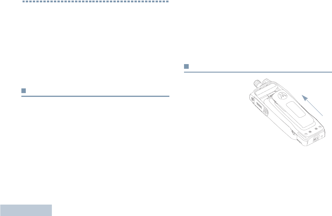
Attaching the Battery
Align the battery with
the rails on the back of
the radio. Press the
battery firmly, and slide
upward until the latch
snaps into place. Slide
battery latch into lock
position.
Preparing Your Radio for Use
English
3
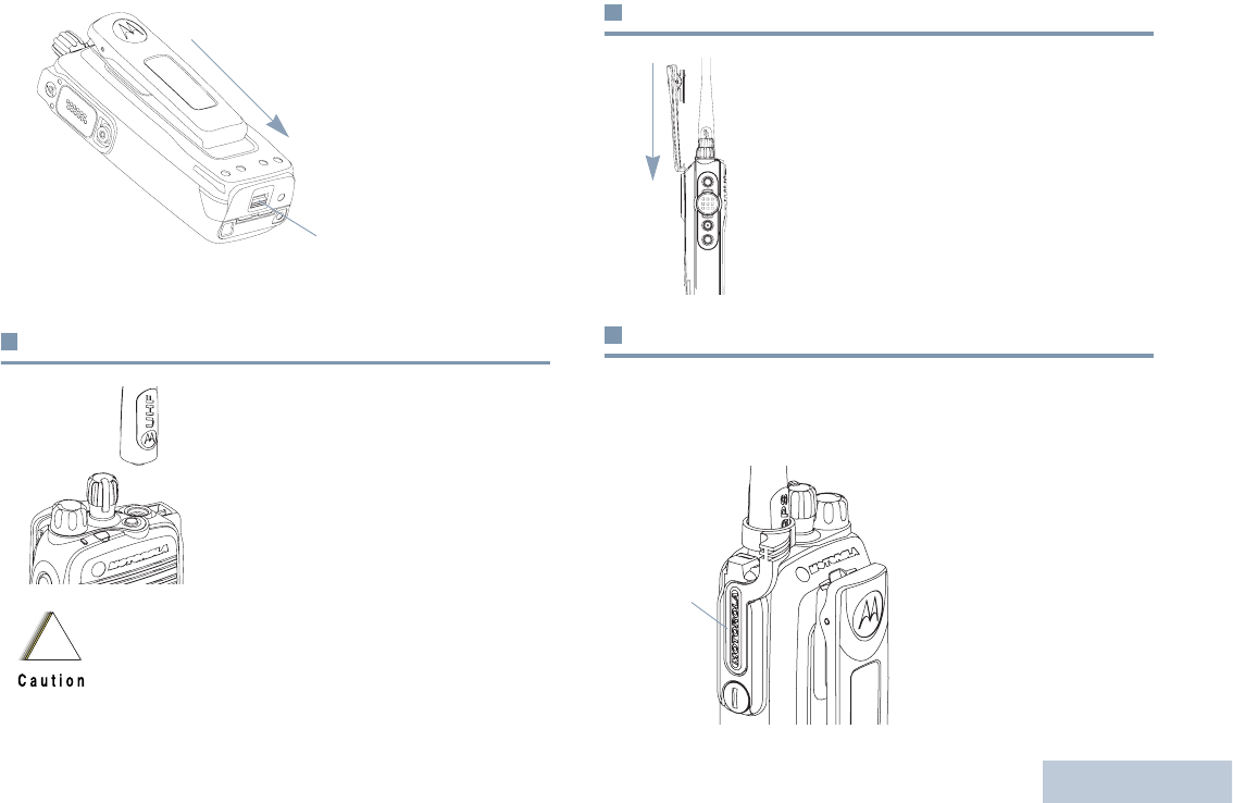
To remove the
battery, turn the
radio off. Move the
battery latch into
unlock position
and hold, and slide
the battery down
and off the rails.
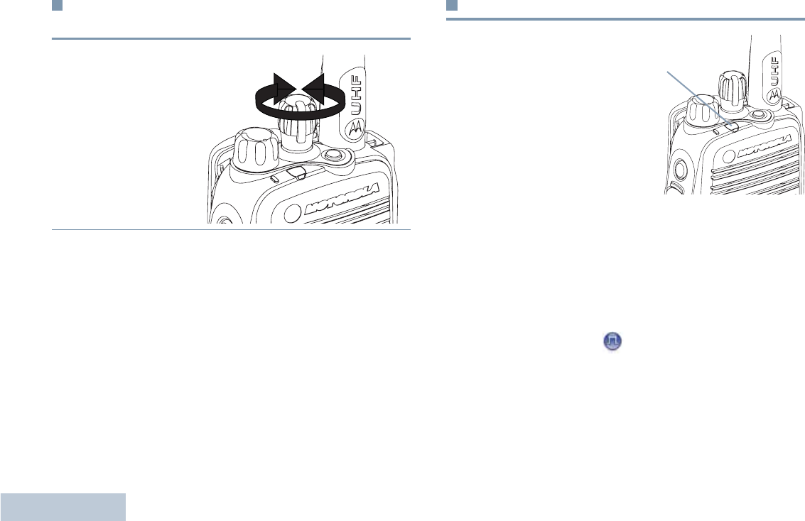
Attaching the Antenna
With the radio turned off, set the
antenna in its receptacle and turn
clockwise.
To remove the antenna, turn the
antenna counterclockwise. Make sure
you turn off the radio and remove the
universal connector cover first.
Attaching the Belt Clip
Align the grooves on the clip with those
on the battery and press downward until
you hear a click.
To remove the clip, press the belt clip
tab away from the battery using a key.
Then slide the clip upward and away
from the radio.
Attaching the Universal Connector Cover
The universal connector is located on the antenna side of the
radio. It is used to connect MOTOTRBO accessories to the
radio.
Place the universal
connector cover loop over
the attached antenna. Slide
it all the way down to the
base of the antenna.
Insert the hooked end of the
cover into the slots above
the universal connector.
If antenna needs to be replaced, ensure that only
MOTOTRBO antennas are used. Neglecting this will
damage your radio. See Antennas on page 25 for a
list of available antennas.
Battery Latch
!
Universal
Connector
Cover
Preparing Your Radio for Use
English
4
Press downward on the cover to seat the lower tab properly into
the RF connector.
Turn the thumbscrew clockwise to secure the connector cover
to the radio.
To remove the universal connector cover, press down on the
cover and turn the thumbscrew counterclockwise. Lift the cover
up, slide the connector cover loop upwards, and remove it from
the attached antenna.
Powering Up the Radio
Rotate the On/Off/Volume
Control Knob clockwise
until you hear a click. The
LED blinks green.
A brief tone sounds,
indicating that the power up
test is successful.
NOTE: There is no power up
tone if the radio
tones/alerts
function is disabled
(see Turning
Radio Tones/
Alerts On or Off on
page 24).
If your radio does not power up, check your battery. Make sure
that it is charged and properly attached. If your radio still does
not power up, contact your dealer.
To turn off the radio, rotate this knob counterclockwise until you
hear a click.
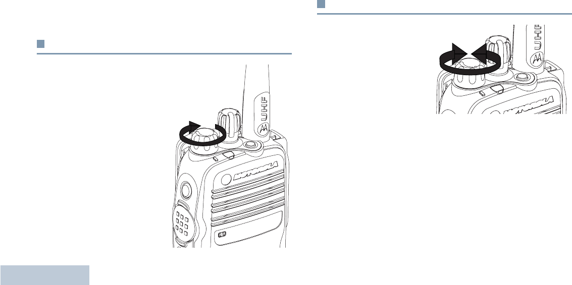
Adjusting the Volume
To increase the
volume, turn the On/
Off/Volume Control
Knob clockwise.
To decrease the
volume, turn this knob
counterclockwise.
Identifying Radio Controls
English
5
Identifying Radio Controls
Take a moment to review the following:
Radio Controls You Will Be Using . . . . . . . . . . . . . . . . . page 5
Programmable Buttons . . . . . . . . . . . . . . . . . . . . . . . . . page 6
Push-To-Talk (PTT) Button . . . . . . . . . . . . . . . . . . . . . . page 7
Switching Between Analog and Digital Mode . . . . . . . . page 7
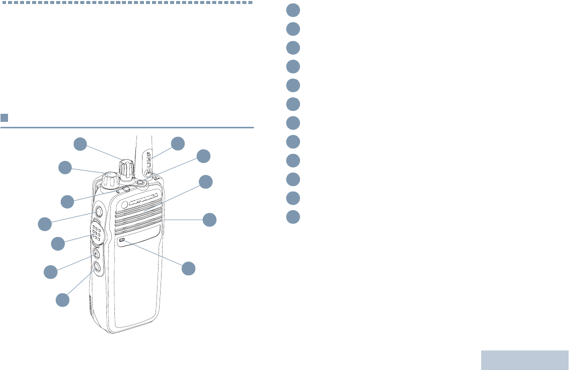
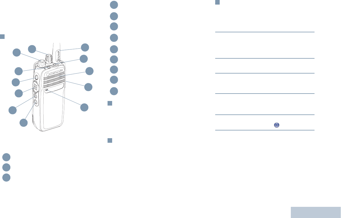
Radio Controls You Will Be Using
12
8
6
5
2
1
11
4
10
3
9
7
Channel Selector Knob
On/Off/Volume Control Knob
LED Indicator
Side Button 1*
Push-to-Talk (PTT) Button
Side Button 2*
Side Button 3*
Microphone
Universal Connector for Accessories
Speaker
Emergency Button*
Antenna
* These buttons are programmable.
1
2
3
4
5
6
7
8
9
10
11
12

Identifying Radio Controls
English
6
Programmable Buttons
Your dealer can program the programmable buttons as
shortcuts to radio functions or preset channels/groups
depending on the duration of a button press:
•Press –Pressing and releasing rapidly.
•Long press –Pressing and holding for the programmed
duration (between 0.25 seconds and 3.75 seconds).
•Hold down –Keeping the button pressed.
Assignable Radio Functions
Emergency –Depending on the programming, initiates or
cancels an emergency alarm or call.
Monitor –Monitors a selected channel for activity.
Nuisance Channel Delete –Temporarily removes an
unwanted channel, except for the Selected Channel, from the
scan list. The Selected Channel refers to the user’s selected
zone/channel combination from which scan is initiated.
One Touch Call –Directly initiates a predefined Private or
Group Call, a Call Alert or a Quick Text message.
Option Board Feature –Toggles option board feature(s) on or
off for option board-enabled channels.
Permanent Monitor –Monitors a selected channel for all radio
traffic until function is disabled.
Privacy –Toggles privacy on or off.
Repeater/Talkaround –Toggles between using a repeater and
communicating directly with another radio.
Scan –Toggles scan on or off.
Telemetry Control –Controls the Output Pin on a local or
remote radio.
Zone –Allows selection from a list of zones.
Battery Strength –Indicates battery strength via the LED
Indicator.
Assignable Settings or Utility Functions
All Tones/Alerts –Toggles all tones and alerts on or off.
Power Level –Toggles transmit power level between high and
low.
Squelch –Toggles squelch level between tight and normal.
Identifying Radio Controls
English
7
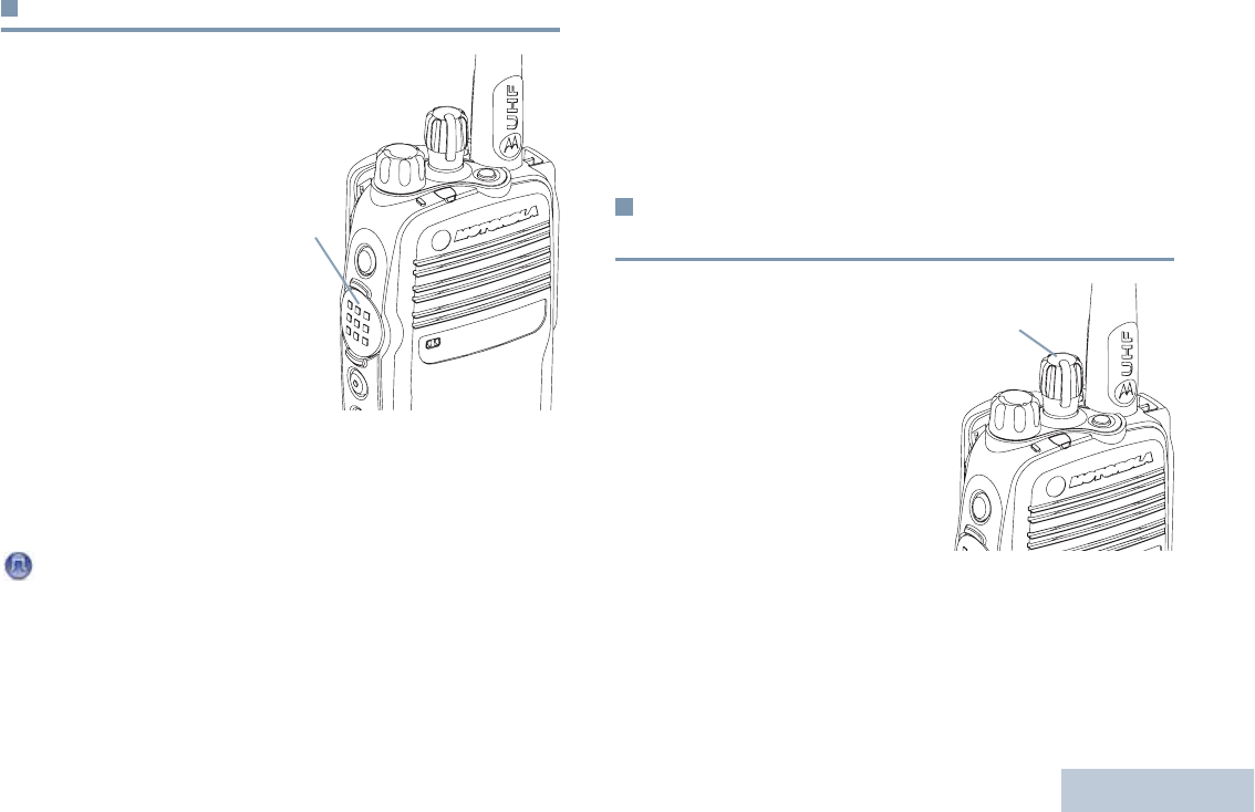
Push-To-Talk (PTT) Button
The PTT button on the side of
the radio serves two basic
purposes:
•While a call is in progress,
the PTT button allows the
radio to transmit to other
radios in the call.
Press and hold down PTT
button to talk. Release the
PTT button to listen.
The microphone is activated
when the PTT button is
pressed.
•While a call is not in progress, the PTT button is used to make
a new call (see Making a Radio Call on page 12).
Depending on programming, if the Talk Permit Tone is enabled,
wait until the short alert tone ends before talking.
During a call, if the Channel Free Indication feature is
enabled on your radio (programmed by your dealer), you
will hear a short alert tone the moment the target radio (the
radio that is receiving your call) releases the PTT button,
indicating the channel is free for you to respond.
You will also hear the Channel Free Indication tone if your
call is interrupted, for example when the radio receives an
Emergency Call.
You can turn off the Channel Free Indication tone by
disabling all radio tones and alerts (see Turning Radio
Tones/Alerts On or Off on page 24).
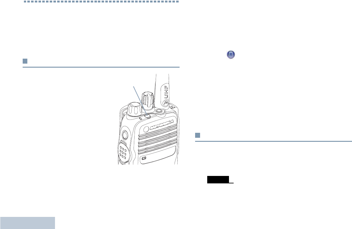
Switching Between Analog and Digital
Mode
Each channel in your radio
can be configured as an
analog channel or a digital
channel. Use the Channel
Selector Knob to switch
between an analog or a digital
channel.
When switching from digital to
analog mode, certain features
are unavailable.
Your radio also has features available in both analog and digital
mode. However, the minor differences in the way each feature
works does NOT affect the performance of your radio.
NOTE: Your radio also switches between digital and analog
modes during a dual mode scan (see Scan on
page 16).
PTT
Button
Channel Selector Knob
Identifying Status Indicators
English
8
Identifying Status Indicators
Your radio indicates its operational status through the following:
LED Indicator . . . . . . . . . . . . . . . . . . . . . . . . . . . . . . . . page 8
Audio Tones . . . . . . . . . . . . . . . . . . . . . . . . . . . . . . . . . page 8
Indicator Tones . . . . . . . . . . . . . . . . . . . . . . . . . . . . . . . page 8
LED Indicator
The LED indicator shows the
operational status of your radio.
Blinking red –Radio is
transmitting at low battery
condition, receiving an emergency
transmission or has failed the self-
test upon powering up.
Solid yellow –Radio is monitoring
a channel. Also indicates fair
battery charge when the
programmed Battery Strength
button is pressed.
Blinking yellow – Radio is scanning for activity or receiving a
Call Alert.
Solid green –Radio is transmitting. Also indicates full charge of
the battery when the programmed Battery Strength button is
pressed.
Blinking green –Radio is powering up, receiving a non-
privacy-enabled call or data, or detecting activity over the air.
Rapidly blinking green –Radio is receiving a privacy-enabled
call or data.
NOTE: When the LED blinks green, it indicates the radio
detects activity over the air. Due to the nature of the
digital protocol, this activity may or may not affect the
radio's programmed channel.
Upon a PTT button press, if the radio is programmed
for polite operation, the radio automatically determines
whether a transmission is permitted via a Talk Permit
or a Talk Denial tone.
Audio Tones
Alert tones provide you with audible indications of the radio’s
status or the radio’s response to data received.
LED Indicator
Continuous Tone A monotone sound. Sounds
continuously until termination.
Receiving and Making Calls
English
9
Indicator Tones
High pitched tone Low pitched tone
Receiving and Making Calls
Once you understand how your MOTOTRBO Portable is
configured, you are ready to use your radio.
Use this navigation guide to familiarize yourself with the basic
Call features:
Selecting a Zone . . . . . . . . . . . . . . . . . . . . . . . . . . . . . .page 9
Selecting a Radio Channel, Subscriber ID,
or Group ID. . . . . . . . . . . . . . . . . . . . . . . . . . . . . . . . page 10
Receiving and Responding to a Radio Call . . . . . . . . . page 10
Making a Radio Call. . . . . . . . . . . . . . . . . . . . . . . . . . . page 12
Talkaround . . . . . . . . . . . . . . . . . . . . . . . . . . . . . . . . . . page 14
Monitoring Features . . . . . . . . . . . . . . . . . . . . . . . . . . . page 15
Selecting a Zone
A zone is a group of channels. Your radio supports up to a
maximum of 2 zones.
Procedure:
1Press the programmed Zone button.
2You hear a positive indicator tone, indicating the radio has
switched from Zone 1 to Zone 2.
OR
You hear a negative indicator tone, indicating the radio has
switched from Zone 2 to Zone 1.
Periodic Tone Sounds periodically depending on the
duration set by the radio. Tone starts.
stops and repeats itself.
Repetitive Tone A single tone that repeats itself until it is
terminated by the user.
Momentary Tone Sounds only once for a short period of
time defined by the radio.
Positive Indicator Tone
Negative Indicator Tone
Receiving and Making Calls
English
10
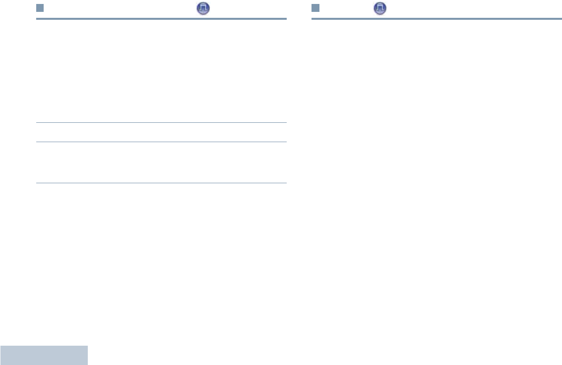
Selecting a Radio Channel, Subscriber ID,
or Group ID
Procedure:
Once the required
zone is set (if you
have multiple zones
in your radio), turn
the Channel
Selector Knob to
select the number
that represents the
channel, subscriber
ID, or group ID.
Receiving and Responding to a Radio Call
Once the channel,
subscriber ID, or group ID
is set, you can proceed to
receive and respond to
calls.
The LED lights up solid
green while the radio is
transmitting and blinks
when the radio is receiving.
NOTE: The LED lights up solid green while the radio is
transmitting and blinks green rapidly when the radio is
receiving a privacy-enabled call.
To unscramble a privacy-enabled call, your radio must
have the same Privacy Key (programmed by your
dealer) as the transmitting radio (the radio you are
receiving the call from). See Privacy on page 22 for
more information.
LED Indicator

Receiving and Making Calls
English
11
Receiving and Responding to a Group Call
To receive a call from a group of users, your radio must be
configured as part of that group.
1The LED blinks green.
2Hold the radio vertically 1 to 2 inches (2.5 to 5.0 cm) from
your mouth.
If the Channel Free Indication feature is enabled, you
will hear a short alert tone the moment the transmitting radio
releases the PTT button, indicating the channel is free for
you to respond.
3Press the PTT button to respond to the call. The LED lights
up solid green.
4Wait for the Talk Permit Tone to finish (if enabled) and speak
clearly into the microphone.
5Release the PTT button to listen.
6If there is no voice activity for a predetermined period of
time, the call ends.
See Making a Group Call on page 12 for details on making a
Group Call.
Receiving and Responding to a Private Call
A Private Call is a call from an individual radio to another
individual radio.
There are two types of Private Calls. The first type, where a
radio presence check is performed prior to setting up the call,
while the other sets up the call immediately.
When your radio is checked, the LED blinks green.
Only one of these call types can be programmed to your radio
by your dealer.
Procedure:
When you receive a private call:
1The LED blinks green.
2Hold the radio vertically 1 to 2 inches (2.5 to 5.0 cm) from
your mouth. If the Channel Free Indication feature is
enabled, you will hear a short alert tone the moment the
transmitting radio releases the PTT button, indicating the
channel is free for you to respond.
3Press the PTT button to respond to the call. The LED lights
up solid green.
4Wait for the Talk Permit Tone to finish (if enabled) and speak
clearly into the microphone.
5Release the PTT button to listen.

Receiving and Making Calls
English
12
6If there is no voice activity for a predetermined period of
time, the call ends.
7You hear a short tone.
See Making a Private Call on page 13 for details on making a
Private Call.
Receiving an All Call
An All Call is a call from an individual radio to every radio on the
channel. It is used to make important announcements requiring
the user’s full attention.
Procedure:
When you receive an All Call:
1A tone sounds and the LED blinks green.
2If there is no voice activity for a predetermined period of
time, the All Call ends.
If the Channel Free Indication feature is enabled, you
will hear a short alert tone the moment the transmitting radio
releases the PTT button, indicating the channel is now
available for use.
You cannot respond to an All Call.
NOTE: The radio stops receiving the All Call if you switch to a
different channel while receiving the call.
During an All Call, you will not be able to use any
programmed button functions until the call ends.
Making a Radio Call
You can select a channel, subscriber ID or group ID by using:
•The Channel Selector Knob
•A programmed One Touch Call button
NOTE: Your radio must have the Privacy feature enabled on
the channel to send a privacy-enabled transmission.
Only target radios with the same Privacy Key as your
radio will be able to unscramble the transmission.
See Privacy on page 22 for more information.
Making a Call with the Channel Selector Knob
Making a Group Call
To make a call to a group of users, your radio must be
configured as part of that group.
Procedure:
1Turn the Channel Selector Knob to select the channel with
the active group ID.
2Hold the radio vertically 1 to 2 inches (2.5 to 5.0 cm) from
your mouth.

Receiving and Making Calls
English
13
3Press the PTT button to make the call. The LED lights up
solid green.
4Wait for the Talk Permit Tone to finish (if enabled) and speak
clearly into the microphone.
5Release the PTT button to listen. When the target radio
responds, the LED blinks green.
6If the Channel Free Indication feature is enabled, you will
hear a short alert tone the moment the target radio releases
the PTT button, indicating the channel is free for you to
respond. Press the PTT button to respond.
OR
If there is no voice activity for a predetermined period of
time, the call ends.
Making a Private Call
Procedure:
1Turn the Channel Selector Knob to select the channel with
the active subscriber ID.
2Hold the radio vertically 1 to 2 inches (2.5 to 5.0 cm) from
your mouth.
3Press the PTT button to make the call. The LED lights up
solid green.
4Wait for the Talk Permit Tone to finish (if enabled) and speak
clearly into the microphone.
5Release the PTT button to listen. When the target radio
responds, the LED blinks green.
6If the Channel Free Indication feature is enabled, you will
hear a short alert tone the moment the target radio releases
the PTT button, indicating the channel is free for you to
respond. Press the PTT button to respond.
OR
If there is no voice activity for a predetermined period of
time, the call ends.
7You hear a short tone.
Making an All Call
This feature allows you to transmit to all users on the channel.
Your radio must be programmed to allow you to use this feature.
Procedure:
1Turn the Channel Selector Knob to select the channel with
the active All Call group ID.
2Hold the radio vertically 1 to 2 inches (2.5 to 5.0 cm) from
your mouth.
3Press the PTT button to make the call. The LED lights up
solid green.
4Wait for the Talk Permit Tone to finish (if enabled) and speak
clearly into the microphone.
Users on the channel cannot respond to an All Call.

Receiving and Making Calls
English
14
Making a Group or Private Call with the One Touch
Call Button
The One Touch Call feature allows you to make a Group or
Private Call to a predefined ID easily. This feature can be
assigned to a short or long programmable button press.
You can ONLY have one ID assigned to a One Touch Call
button. Your radio can have multiple One Touch Call buttons
programmed.
Procedure:
1Press the programmed One Touch Call button to make a
Group or Private Call to the predefined ID.
2Hold the radio vertically 1 to 2 inches (2.5 to 5.0 cm) from
your mouth.
3Press the PTT button to make the call. The LED lights up
solid green.
4Wait for the Talk Permit Tone to finish (if enabled) and speak
clearly into the microphone.
5Release the PTT button to listen. When the target radio
responds, the LED blinks green.
6If the Channel Free Indication feature is enabled, you will
hear a short alert tone the moment the target radio releases
the PTT button, indicating the channel is free for you to
respond. Press the PTT button to respond.
OR
If there is no voice activity for a predetermined period of
time, the call ends.
For a Private Call, you hear a short tone when the call ends.
Talkaround
You can continue to communicate when your repeater is not
operating, or when your radio is out of the repeater’s range but
within talking range of other radios. This is called “talkaround”.
Procedure:
1Press the programmed Repeater/Talkaround button.
2You hear a positive indicator tone, indicating the radio is in
Talkaround mode.
OR
You hear a negative indicator tone, indicating the radio is in
Repeater mode.
The Talkaround setting is retained even after powering down.

Receiving and Making Calls
English
15
Monitoring Features
Monitoring a Channel
Use the Monitor feature to make sure a channel is free before
transmitting.
Procedure:
1Press and hold the programmed Monitor button and listen
for activity.
2You hear radio activity or total silence, depending on how
your radio is programmed.
3When you hear “white noise” (that is, the channel is free),
press the PTT button to talk and release it to listen. The LED
lights up solid yellow.
Permanent Monitor
Use the Permanent Monitor feature to continuously monitor a
selected channel for activity.
Procedure:
1Press the programmed Permanent Monitor button.
2Radio sounds alert tone, and the LED lights up solid yellow.
3Press the programmed Permanent Monitor button to
remove the radio from permanent monitor mode.
4Radio sounds an alert tone and the LED turns off.

Advanced Features
English
16
Advanced Features
Use this navigation guide to learn more about advanced
features available with your radio:
Scan Lists . . . . . . . . . . . . . . . . . . . . . . . . . . . . . . . . . . page 16
Scan . . . . . . . . . . . . . . . . . . . . . . . . . . . . . . . . . . . . . . page 16
Call Indicator Settings . . . . . . . . . . . . . . . . . . . . . . . . . page 18
Call Alert Operation. . . . . . . . . . . . . . . . . . . . . . . . . . . page 18
Emergency Operation . . . . . . . . . . . . . . . . . . . . . . . . . page 19
Text Messaging Features . . . . . . . . . . . . . . . . . . . . . . page 22
Privacy . . . . . . . . . . . . . . . . . . . . . . . . . . . . . . . . . . . . page 22
Utilities. . . . . . . . . . . . . . . . . . . . . . . . . . . . . . . . . . . . . page 23
Scan Lists
Scan lists are created and assigned to individual channels/
groups. Your radio scans for voice activity by cycling through the
channel/group sequence specified in the scan list for the current
channel.
Your radio supports up to 32 scan lists, with a maximum of 16
members in a list. Each scan list shall support a mixture of both
analog and digital entries.
Scan
When you start a scan, your radio cycles through the
programmed scan list for the current channel looking for voice
activity.
The LED blinks yellow.
During a dual mode scan, if you are on a digital channel, and
your radio locks onto an analog channel, it automatically
switches from digital mode to analog mode for the duration of
the call. This is also true for the reverse.
There are two types of scans:
•Main Channel Scan (Manual): Your radio scans all the
channels/groups in your scan list. On entering scan, your
radio may – depending on the settings – automatically start
on the last scanned “active” channel/group or on the channel
where scan was initiated.
•Auto Scan (Automatic): Your radio automatically starts
scanning when you select a channel/group that has Auto
Scan enabled.

Advanced Features
English
17
Starting and Stopping Scan
Procedure:
1Press the programmed Scan button.
OR
Use the Channel Selector Knob to select a channel with
Auto Scan enabled.
2When Scan is enabled, the LED blinks yellow and you hear
a positive indicator tone.
OR
When Scan is disabled, the LED turns off and you hear a
negative indicator tone.
Responding to a Transmission During a Scan
During scanning, your radio stops on a channel/group where
activity is detected. The radio stays on that channel for a
programmed time period known as “hang time”.
Procedure:
1Hold the radio vertically 1 to 2 inches (2.5 to 5.0 cm) from
your mouth.
If the Channel Free Indication feature is enabled, you
will hear a short alert tone the moment the transmitting radio
releases the PTT button, indicating the channel is free for
you to respond.
2Press the PTT button during hang time. The LED lights up
solid green.
3Wait for the Talk Permit Tone to finish (if enabled) and speak
clearly into the microphone.
4Release the PTT button to listen.
5If you do not respond within the hang time, the radio returns
to scanning other channels/groups.
Deleting a Nuisance Channel
If a channel continually generates unwanted calls or noise
(termed a “nuisance” channel), you can temporarily remove the
unwanted channel from the scan list.
This capability does not apply to the channel designated as the
Selected Channel.
Procedure:
1When your radio “locks on to” an unwanted or nuisance
channel, press the programmed Nuisance Channel Delete
button until you hear a tone.
2Release the Nuisance Channel Delete button. The
nuisance channel is deleted.

Advanced Features
English
18
Restoring a Nuisance Channel
Procedure:
To restore the deleted nuisance channel, do one of the
following:
•Power the radio off and powering it on again, OR
•Stop and restart a scan via the programmed Scan button, OR
•Change the channel via the Channel Selector Knob.
Call Indicator Settings
You can turn on or off the ringing tones for a received Private
Call (see Turning Radio Tones/Alerts On or Off on page 24).
Escalating Alarm Tone Volume
Your radio can be programmed by your dealer to continually
alert you when a radio call remains unanswered. This is done
by automatically increasing the alarm tone volume over time.
This feature is known as Escalert.
Call Alert Operation
Call Alert paging enables you to alert a specific radio user to call
you back when they are able to do so. This feature is accessible
via a programmed One Touch Call button.
Receiving and Acknowledging a Call Alert
Procedure:
When you receive a Call Alert page:
1You hear a repetitive tone. The LED blinks yellow.
2Press and release the PTT button to acknowledge the alert.
Making a Call Alert with the One Touch Call
Button
Procedure:
1Press the programmed One Touch Call button to make a
Call Alert to the predefined ID.
2The LED lights up solid green when your radio is sending
the Call Alert.
3If the Call Alert acknowledgement is received, two chirps
sounds.
OR
If the Call Alert acknowledgement is not received, a low-
pitch tone sounds.

Advanced Features
English
19
Emergency Operation
An Emergency Alarm is used to indicate a critical situation. You
are able to initiate an Emergency at any time, in any state, even
when there is activity on the current channel.
Your radio supports 3 Emergency Alarms:
•Emergency Alarm
•Emergency Alarm with Call
•Emergency Alarm with Voice to Follow
In addition, each alarm has the following types:
•Regular –Radio transmits an alarm signal and shows audio
and/or visual indicators.
•Silent –Radio transmits an alarm signal without any audio or
visual indicators. There will be no response (call) from the
target radio until you press the PTT button to initiate the call.
•Silent with Voice – Radio transmits an alarm signal and is
able to receive an incoming call, without any audio or visual
indicators, until you press the PTT button to initiate, or
respond to, the call.
Only one of the Emergency Alarms above can be assigned to
the programmed Emergency button.
Sending an Emergency Alarm
This feature allows you to send an Emergency Alarm, a non-
voice signal, which triggers an alert indication on another radio.
Procedure:
1Press the programmed Emergency button.
2The LED lights up solid green.
3When an Emergency Alarm acknowledgment is received,
the Emergency tone sounds. The LED blinks green.
OR
If your radio does not receive an Emergency Alarm
acknowledgement, and after all retries have been
exhausted, a low-pitch tone sounds.
4Radio exits the Emergency Alarm mode.
If your radio is set to Silent, it will not display any audio or visual
indicators during Emergency mode.
Advanced Features
English
20
Sending an Emergency Alarm with Call
This feature allows you send an Emergency Alarm to another
radio. Upon acknowledgement, both radios can communicate
over a programmed Emergency channel.
Procedure:
1Press the programmed Emergency button.
2The LED lights up solid green.
3When an Emergency Alarm acknowledgment is received,
the Emergency tone sounds. The LED blinks green.
4Hold the radio vertically 1 to 2 inches (2.5 to 5.0 cm) from
your mouth.
5Press the PTT button to make the call. The LED lights up
solid green.
6Wait for the Talk Permit Tone to finish (if enabled) and speak
clearly into the microphone.
7Release the PTT button to listen.
8If the Channel Free Indication feature is enabled, you will
hear a short alert tone the moment the target radio releases
the PTT button, indicating the channel is free for you to
respond. Press the PTT button to respond.
OR
Long press the programmed Emergency button to exit the
Emergency mode.
If your radio is set to Silent, it will not display any audio or visual
indicators during Emergency mode, or receive any response
(call) from the target radio, until you press the PTT button to
initiate the call.
If your radio is set to Silent with Voice, it will not display any
audio or visual indicators during Emergency mode, or when you
are receiving a call from the target radio. The indicators will only
appear once you press the PTT button to initiate, or respond to,
the call.
Sending an Emergency Alarm with Voice to
Follow
This feature allows you to send an Emergency Alarm to another
radio. Upon acknowledgement, your radio’s microphone is
automatically activated, allowing you to communicate with the
other radio without pressing the PTT button.
This activated microphone state is also known as “hot mic”.
If you press the PTT button during the programmed hot mic
transmission period, the radio ignores the PTT press and
remains in Emergency mode.
NOTE: If you press the PTT button during hot mic, and
continue to press it after the hot mic duration expires,
the radio continues to transmit until you release the
PTT button.

Advanced Features
English
21
Procedure:
1Press the programmed Emergency button.
2The LED lights up solid green.
3Once a tone sounds, speak clearly into the microphone.
When hot mic has been enabled, the radio automatically
transmits without a PTT press until the hot mic duration
expires.
4While transmitting, the LED lights up solid green.
5Once the hot mic duration expires, the radio automatically
stops transmitting.To transmit again, press the PTT button
If your radio is set to Silent, it will not display any audio or visual
indicators during Emergency mode, or receive any response
from the target radio, until the programmed hot mic transmission
period is over, and you press the PTT button.
If your radio is set to Silent with Voice, it will not display any
audio or visual indicators during Emergency mode when you
are making the call with hot mic, or when the target radio
responds after the programmed hot mic transmission period is
over. The indicators will only appear when you press the PTT
button.
Reinitiating an Emergency Mode
There are two instances where this can happen:
•You change the channel while the radio is in Emergency
mode. This exits the Emergency mode. If Emergency Alarm is
enabled on this new channel, the radio reinitiates Emergency.
•You press the programmed Emergency button during an
Emergency initiation/transmission state. This causes the
radio to exit this state, and to reinitiate Emergency.
Exiting an Emergency Mode
Your radio exits Emergency mode when one of the following
occurs:
•Emergency Alarm acknowledgement is received (for
Emergency Alarm only), OR
•All retries to send the alarm have been exhausted, OR
•The programmed Emergency button is long pressed.
NOTE: If your radio is powered off, it exits the Emergency
mode. The radio will not reinitiate the Emergency
mode automatically when it is turned on again.
Advanced Features
English
22
Text Messaging Features
Sending a Quick Text Message
You can send Quick Text messages, programmed by your
dealer, via the programmable button.
Procedure:
1Press the programmed One Touch Call button to send a
predefined Quick Text message to a predefined ID.
2The LED lights up solid green.
3Two chirps indicate that the message is sent successfully.
OR
A low-pitch tone indicates that the message cannot be sent.
Privacy
If enabled, this feature helps to prevent eavesdropping by
unauthorized users on a channel by the use of a software-
based scrambling solution. The signaling and user identification
portions of a transmission are not scrambled.
Your radio must have privacy enabled on the channel to
send a privacy-enabled transmission, although this is not a
necessary requirement for receiving a transmission. While on a
privacy-enabled channel, the radio is still able to receive clear
(unscrambled) transmissions.
To unscramble a privacy-enabled call or data transmission, your
radio must have the same Privacy Key (programmed by your
dealer) as the transmitting radio. If your radio receives a
scrambled call that is of a different Privacy Key, you will hear a
garbled transmission.
The LED lights up solid green while the radio is transmitting and
blinks green rapidly when the radio is receiving an ongoing
privacy-enabled transmission.
NOTE: Some radio models may not offer this Privacy feature.
Check with your dealer or system administrator for
more information.
Procedure:
Press the programmed Privacy button to toggle privacy on or
off.

Advanced Features
English
23
Utilities
Setting the Squelch Level
You can adjust your radio's squelch level to filter out unwanted
calls with low signal strength or channels that have a higher
than normal background noise.
Settings: Normal is the default. Tight filters out (unwanted)
calls and/or background noise. However, calls from remote
locations may also be filtered out.
Procedure:
1Press the programmed Squelch button.
2You hear a positive indicator tone, indicating the radio is
operating in tight squelch.
OR
You hear a negative indicator tone, indicating the radio is
operating in normal squelch.
Setting the Power Level
You can toggle your radio’s power setting between high or low
for each channel.
Settings: High enables communication with radios located at a
considerable distance from you. Low enables communication
with radios in closer proximity.
Procedure:
1Press the programmed Power Level button.
2You hear a positive indicator tone, indicating the radio is
transmitting at low power.
OR
You hear a negative indicator tone, indicating the radio is
transmitting at high power.

Advanced Features
English
24
Turning the Option Board Feature(s) On or Off
A channel can support up to 6 option board features. Refer to
your dealer or system administrator for more information.
Procedure:
Press the programmed Option Board Feature button to toggle
the feature on or off.
Turning Radio Tones/Alerts On or Off
You can enable and disable all radio tones and alerts (except for
the incoming Emergency alert tone) if needed.
Procedure:
1Press the programmed All Tones/Alerts button.
2You hear a positive indicator tone, indicating all tones and
alerts are on.
OR
You hear a negative indicator tone, indicating all tones and
alerts are off.
Checking the Battery Strength
You can check how much battery power you have left.
Settings: The LED Indicator in solid yellow indicates fair battery
charge while solid green indicates full charge of the battery.
Procedure:
Press the programmed Battery Strength button to view the
battery strength via the LED Indicator.
Accessories
English
25
Accessories
Your radio is compatible with the accessories listed in this
chapter. Contact your dealer for details.
Antennas . . . . . . . . . . . . . . . . . . . . . . . . . . . . . . . . . . . page 25
Batteries . . . . . . . . . . . . . . . . . . . . . . . . . . . . . . . . . . . page 26
Carry Devices . . . . . . . . . . . . . . . . . . . . . . . . . . . . . . . page 26
Chargers . . . . . . . . . . . . . . . . . . . . . . . . . . . . . . . . . . . page 27
Earbuds and Earpieces . . . . . . . . . . . . . . . . . . . . . . . . page 27
Headsets and Headset Accessories . . . . . . . . . . . . . . page 27
Remote Speaker Microphones . . . . . . . . . . . . . . . . . . page 28
Surveillance Accessories. . . . . . . . . . . . . . . . . . . . . . . page 28
Miscellaneous Accessories . . . . . . . . . . . . . . . . . . . . . page 29
Antennas
The diagram on the right shows the location of
the color indicator for the following antennas. See
the footnote at the end of the list for the colors.
•Combination VHF/GPS, 136 – 147 MHz, Helical Antenna4
(PMAD4067_)
•Combination VHF/GPS, 147 – 160 MHz, Helical Antenna3
(PMAD4068_)
•Combination VHF/GPS, 160 – 174 MHz, Helical Antenna5
(PMAD4069_)
•VHF Wideband, 136 – 174 MHz, Double Helical Antenna6
(PMAD4088_)
•Combination UHF/GPS, 403 – 433 MHz, Folded Monopole
Antenna1 (PMAE4018_)
•Combination UHF/GPS, 403 – 433 MHz, Stubby Antenna1
(PMAE4021_)
•UHF, 403 – 470 MHz, Whip Antenna3 (PMAE4022_)
•Combination UHF/GPS, 430 – 470 MHz, Stubby Antenna2
(PMAE4023_)
•Combination UHF/GPS, 430 – 470 MHz, Folded Monopole
Antenna2 (PMAE4024_)
•Public Safety Microphone UHF Stubby Antenna1,
403 – 433 MHz (PMAE4046_)
•Public Safety Microphone UHF Stubby Antenna2,
430 – 470 MHz (PMAE4047_)
•UHF2, 450 – 527 MHz, Whip Antenna7 (PMAE4049_)
•Combination UHF2/GPS, 450 – 495 MHz, Folded Monopole
Antenna8 (PMAE4050_)

Accessories
English
26
•Combination UHF2/GPS, 495 – 527 MHz, Folded Monopole
Antenna6 (PMAE4051_)
•Combination UHF2/GPS, 450 – 495 MHz, Stubby Antenna8
(PMAE4052_)
•Combination UHF2/GPS, 495 – 527 MHz, Stubby Antenna6
(PMAE4048_)
•Public Safety Microphone VHF Antenna5,
150 – 174 MHz (PMAD4086_)
•Public Safety Microphone VHF Antenna4,
136 – 153 MHz (PMAD4087_)
Color Code:
Batteries
•IMPRES Li-Ion, 1500 mAh Submersible (IP57) Battery
(PMNN4066_)
•IMPRES Li-Ion, 1400 mAh Submersible (IP57) Battery,
Intrinsically Safe (FM) (PMNN4069_)
•IMPRES Li-Ion, 2200 mAh Submersible (IP57) Battery
(PMNN4077_)
•NiMH, 1300 mAh Submersible (IP57) Battery (PMNN4065_)
Carry Devices
•Belt Clip for 2-Inch Belt Width (PMLN4651_)
•Belt Clip for 2.5-Inch Belt Width (PMLN4652_)
•2.5-Inch Replacement Swivel Belt Loop (PMLN5022_)
•3-Inch Replacement Swivel Belt Loop (PMLN5023_)
•Nylon Carry Case with 3-Inch Fixed Belt Loop for
Non-Display Radio (PMLN5024_)
•Soft Leather Carry Case with 2.5-Inch Swivel Belt Loop for
Non-Display Radio (PMLN5025_)
•Soft Leather Carry Case with 3-Inch Swivel Belt Loop for
Non-Display Radio (PMLN5026_)
•Soft Leather Carry Case with 3-Inch Fixed Belt Loop for
Non-Display Radio (PMLN5027_)
•Hard Leather Carry Case with 2.5-Inch Swivel Belt Loop for
Non-Display Radio (PMLN5028_)
•Hard Leather Carry Case with 3-Inch Swivel Belt Loop for
Non-Display Radio (PMLN5029_)
•Hard Leather Carry Case with 3-Inch Fixed Belt Loop for
Non-Display Radio (PMLN5030_)
•1.75-Inch Black Leather Belt (4200865599)
1Red 3Black 5Blue 7Brown
2Green 4Yellow 6White 8Orange

Accessories
English
27
Chargers
•IMPRES Multi-Unit Charger (WPLN4212_)
•IMPRES Multi-Unit Charger with Displays (WPLN4219_)
•IMPRES Single-Unit Charger (WPLN4232_)
Earbuds and Earpieces
•Receive-Only Earbud (AARLN4885_)
•D-Shell Receive-Only Earpiece (PMLN4620_)
•Receive-Only Earpiece (RLN4941_)
•Over-the-Ear Receiver for Remote Speaker Microphone
(WADN4190_)
•D-Shell Earset (PMLN5096_)
•IMPRES Temple Transducer (PMLN5101_)
•Small Custom Earpiece for Surveillance Kits, Right Ear
(RLN4760_)
•Medium Custom Earpiece for Surveillance Kits, Right Ear
(RLN4761_)
•Large Custom Earpiece for Surveillance Kits, Right Ear
(RLN4762_)
•Small Custom Earpiece for Surveillance Kits, Left Ear
(RLN4763_)
•Medium Custom Earpiece for Surveillance Kits, Left Ear
(RLN4764_)
•Large Custom Earpiece for Surveillance Kits, Left Ear
(RLN4765_)
•Standard Earpiece, Black (RLN6279_)
•Standard Earpiece, Beige (RLN6280_)
•Replacement Foam Ear Pad and Windscreen (RLN6283_)
•Earpiece with Acoustic Tube Assembly, Beige (RLN6284_)
•Earpiece with Acoustic Tube Assembly, Black (RLN6285_)
•Earpiece with High Noise Kit, Beige (RLN6288_)
•Earpiece with High Noise Kit, Black (RLN6289_)
Headsets and Headset Accessories
•Ultra-Lite Headset (PMLN5102_)
•Lightweight Headset (RMN5058_)

Accessories
English
28
Remote Speaker Microphones
•Remote Speaker Microphone (PMMN4024_)
•IMPRES Remote Speaker Microphone (PMMN4025_)
•Remote Speaker Microphone, Submersible (IP57)
(PMMN4040_)
•IMPRES Public Safety Microphone (PSM), 30-Inch Cable
(PMMN4041_)*
•IMPRES Public Safety Microphone (PSM), 24-Inch Cable
(PMMN4042_)*
•IMPRES Public Safety Microphone (PSM), 18-Inch Cable
(PMMN4043_)*
•IMPRES Remote Speaker Microphone, with Volume, IP57
(PMMN4046_)
•IMPRES Submersible Public Safety Microphone, 30-Inch
Cable (PMMN4047_)*
•IMPRES Submersible Public Safety Microphone, 24-Inch
Cable (PMMN4048_)*
•IMPRES Submersible Public Safety Microphone, 18-Inch
Cable (PMMN4049_)*
•IMPRES Remote Speaker Microphone, Noise-Canceling
(PMMN4050_)
•Remote Speaker Microphone Replacement Coil Cord Kit (For
Use with PMMN4024_ and PMMN4040_) (RLN6074_)
•Remote Speaker Microphone Replacement Coil Cord Kit (For
Use with PMMN4025) (RLN6075_)
*Only applicable to UHF B1 (403 – 470 MHz) and
VHF (136 – 174 MHz) bands.
Surveillance Accessories
•IMPRES 3-Wire Surveillance, Black (PMLN5097_)
•IMPRES 3-Wire Surveillance, Beige (PMLN5106_)
•IMPRES 3-Wire Surveillance Kit with Clear, Comfortable
Acoustic Tube, Black (PMLN5111_)
•IMPRES 3-Wire Surveillance Kit with Clear, Comfortable
Acoustic Tube, Beige (PMLN5112_)
•Receive Only Surveillance Kit, Black (Single Wire)
(RLN5878_)
•Receive Only Surveillance Kit, Beige (Single Wire)
(RLN5879_)

Accessories
English
29
•IMPRES 2-Wire Surveillance Kit, Black (RLN5880_)
•IMPRES 2-Wire Surveillance Kit, Beige (RLN5881_)
•IMPRES 2-Wire Surveillance Kit with Clear, Comfortable
Acoustic Tube, Black (RLN5882_)
•IMPRES 2-Wire Surveillance Kit with Clear, Comfortable
Acoustic Tube, Beige (RLN5883_)
•Surveillance Low Noise Kit (RLN5886_)
•Surveillance High Noise Kit (RLN5887_)
Miscellaneous Accessories
•Universal Chest Pack (HLN6602_)
•Waterproof Bag, Includes Large Carry Strap (HLN9985_)
•Shoulder Strap (Attaches to D-Rings on Carry Case)
(NTN5243_)
•Small Clip, Epaulet Strap (RLN4295_)
•Break-A-Way Chest Pack (RLN4570_)
•Universal RadioPAK and Utility Case (Fanny Pack)
(RLN4815_)
•Replacement Ear Tips, Clear, Pack of 25 (For Use with
RLN5886_) (RLN6282_)
•Replacement Strap for RLN4570_ and HLN6602_ Chest
Packs (1505596Z02)
•Accessory Dust Cover (1571477L01)
•Replacement Foam Plugs, Pack of 50 (For Use with
RLN5887_) (5080384F72)
•Universal RadioPAK Extension Belt (4280384F89)

Notes
English
30
Notes
Batteries and Chargers Warranty
English
31
Batteries and Chargers Warranty
The Workmanship Warranty
The workmanship warranty guarantees against defects in
workmanship under normal use and service.
The Capacity Warranty
The capacity warranty guarantees 80% of the rated capacity for the
warranty duration.
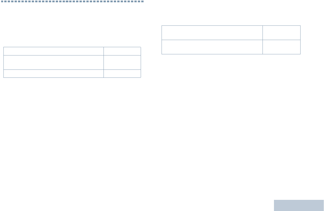
All MOTOTRBO Batteries Two (2) Years
IMPRES Chargers (Single-Unit and Multi-Unit,
Non-Display) Two (2) Years
IMPRES Chargers (Multi-Unit with Display) One (1) Year
Nickel Metal-Hydride (NiMH) or Lithium-Ion
(Li-lon) Batteries 12 Months
IMPRES Batteries, When Used Exclusively
with IMPRES Chargers 18 Months

Limited Warranty
English
32
Limited Warranty
MOTOROLA COMMUNICATION PRODUCTS
I. WHAT THIS WARRANTY COVERS AND FOR HOW
LONG:
MOTOROLA INC. (“MOTOROLA”) warrants the MOTOROLA
manufactured Communication Products listed below (“Product”)
against defects in material and workmanship under normal use and
service for a period of time from the date of purchase as scheduled
below:
MOTOROLA, at its option, will at no charge either repair the
Product (with new or reconditioned parts), replace it (with a new or
reconditioned Product), or refund the purchase price of the Product
during the warranty period provided it is returned in accordance
with the terms of this warranty. Replaced parts or boards are
warranted for the balance of the original applicable warranty period.
All replaced parts of Product shall become the property of
MOTOROLA.
This express limited warranty is extended by MOTOROLA to the
original end user purchaser only and is not assignable or
transferable to any other party. This is the complete warranty for the
Product manufactured by MOTOROLA. MOTOROLA assumes no
obligations or liability for additions or modifications to this warranty
unless made in writing and signed by an officer of MOTOROLA.
Unless made in a separate agreement between MOTOROLA and
the original end user purchaser, MOTOROLA does not warrant the
installation, maintenance or service of the Product.
MOTOROLA cannot be responsible in any way for any ancillary
equipment not furnished by MOTOROLA which is attached to or
used in connection with the Product, or for operation of the Product
with any ancillary equipment, and all such equipment is expressly
excluded from this warranty. Because each system which may use
the Product is unique, MOTOROLA disclaims liability for range,
coverage, or operation of the system as a whole under this
warranty.
II. GENERAL PROVISIONS:
This warranty sets forth the full extent of MOTOROLA'S
responsibilities regarding the Product. Repair, replacement or
refund of the purchase price, at MOTOROLA’s option, is the
exclusive remedy. THIS WARRANTY IS GIVEN IN LIEU OF ALL
OTHER EXPRESS WARRANTIES. IMPLIED WARRANTIES,
INCLUDING WITHOUT LIMITATION, IMPLIED WARRANTIES OF
MERCHANTABILITY AND FITNESS FOR A PARTICULAR
PURPOSE, ARE LIMITED TO THE DURATION OF THIS LIMITED
WARRANTY. IN NO EVENT SHALL MOTOROLA BE LIABLE FOR
DAMAGES IN EXCESS OF THE PURCHASE PRICE OF THE
PRODUCT, FOR ANY LOSS OF USE, LOSS OF TIME,
INCONVENIENCE, COMMERCIAL LOSS, LOST PROFITS OR
SAVINGS OR OTHER INCIDENTAL, SPECIAL OR
CONSEQUENTIAL DAMAGES ARISING OUT OF THE USE OR
XPR Series Digital Portable
Radios Two (2) Years
Product Accessories (Excluding
Batteries and Chargers) One (1) Year

Limited Warranty
English
33
INABILITY TO USE SUCH PRODUCT, TO THE FULL EXTENT
SUCH MAY BE DISCLAIMED BY LAW.
III. STATE LAW RIGHTS:
SOME STATES DO NOT ALLOW THE EXCLUSION OR
LIMITATION OF INCIDENTAL OR CONSEQUENTIAL DAMAGES
OR LIMITATION ON HOW LONG AN IMPLIED WARRANTY
LASTS, SO THE ABOVE LIMITATION OR EXCLUSIONS MAY
NOT APPLY.
This warranty gives specific legal rights, and there may be other
rights which may vary from state to state.
IV. HOW TO GET WARRANTY SERVICE:
You must provide proof of purchase (bearing the date of purchase
and Product item serial number) in order to receive warranty
service and, also, deliver or send the Product item, transportation
and insurance prepaid, to an authorized warranty service location.
Warranty service will be provided by MOTOROLA through one of its
authorized warranty service locations. If you first contact the
company which sold you the Product (e.g., dealer or
communication service provider), it can facilitate your obtaining
warranty service. You can also call MOTOROLA at 1-800-927-2744
US/Canada.
V. WHAT THIS WARRANTY DOES NOT COVER:
A) Defects or damage resulting from use of the Product in other
than its normal and customary manner.
B) Defects or damage from misuse, accident, water, or neglect.
C)Defects or damage from improper testing, operation,
maintenance, installation, alteration, modification, or adjustment.
D)Breakage or damage to antennas unless caused directly by
defects in material workmanship.
E) A Product subjected to unauthorized Product modifications,
disassembles or repairs (including, without limitation, the addition
to the Product of non-MOTOROLA supplied equipment) which
adversely affect performance of the Product or interfere with
MOTOROLA's normal warranty inspection and testing of the
Product to verify any warranty claim.
F) Product which has had the serial number removed or made
illegible.
G)Rechargeable batteries if:
(1) any of the seals on the battery enclosure of cells are broken
or show evidence of tampering.
(2) the damage or defect is caused by charging or using the
battery in equipment or service other than the Product for which it
is specified.
H)Freight costs to the repair depot.
I) A Product which, due to illegal or unauthorized alteration of the
software/firmware in the Product, does not function in
accordance with MOTOROLA’s published specifications or the
FCC type acceptance labeling in effect for the Product at the time
the Product was initially distributed from MOTOROLA.
J) Scratches or other cosmetic damage to Product surfaces that
does not affect the operation of the Product.
K) Normal and customary wear and tear.

Limited Warranty
English
34
VI. PATENT AND SOFTWARE PROVISIONS:
MOTOROLA will defend, at its own expense, any suit brought
against the end user purchaser to the extent that it is based on a
claim that the Product or parts infringe a United States patent, and
MOTOROLA will pay those costs and damages finally awarded
against the end user purchaser in any such suit which are
attributable to any such claim, but such defense and payments are
conditioned on the following:
A) that MOTOROLA will be notified promptly in writing by such
purchaser of any notice of such claim;
B) that MOTOROLA will have sole control of the defense of such
suit and all negotiations for its settlement or compromise; and
C)should the Product or parts become, or in MOTOROLA’s opinion
be likely to become, the subject of a claim of infringement of a
United States patent, that such purchaser will permit
MOTOROLA, at its option and expense, either to procure for
such purchaser the right to continue using the Product or parts or
to replace or modify the same so that it becomes non-infringing
or to grant such purchaser a credit for the Product or parts as
depreciated and accept its return. The depreciation will be an
equal amount per year over the lifetime of the Product or parts as
established by MOTOROLA.
MOTOROLA will have no liability with respect to any claim of patent
infringement which is based upon the combination of the Product or
parts furnished hereunder with software, apparatus or devices not
furnished by MOTOROLA, nor will MOTOROLA have any liability
for the use of ancillary equipment or software not furnished by
MOTOROLA which is attached to or used in connection with the
Product. The foregoing states the entire liability of MOTOROLA with
respect to infringement of patents by the Product or any parts
thereof.
Laws in the United States and other countries preserve for
MOTOROLA certain exclusive rights for copyrighted MOTOROLA
software such as the exclusive rights to reproduce in copies and
distribute copies of such MOTOROLA software. MOTOROLA
software may be used in only the Product in which the software was
originally embodied and such software in such Product may not be
replaced, copied, distributed, modified in any way, or used to
produce any derivative thereof. No other use including, without
limitation, alteration, modification, reproduction, distribution, or
reverse engineering of such MOTOROLA software or exercise of
rights in such MOTOROLA software is permitted. No license is
granted by implication, estoppel or otherwise under MOTOROLA
patent rights or copyrights.
VII. GOVERNING LAW:
This Warranty is governed by the laws of the State of Illinois, U.S.A.
English
m
XPR Series Digital
Portable Radios
Quick Reference Card
Radio Controls
Record your radio’s programmable button
functions in the blanks provided. SP represents
Short Press, LP represents Long Press.
Powering Up and Down the Radio
Rotate the On/Off/Volume Control Knob
clockwise until you hear a click to turn the radio
on, and counterclockwise until you hear a click to
turn it off.
Adjusting the Volume
Turn the On/Off/Volume Control Knob clockwise
to increase volume or counterclockwise to
decrease volume.
LED Indicator
Blinking red – Radio is transmitting at low
battery condition, receiving an emergency
transmission or has failed the self-test upon
powering up.
Solid yellow – Radio is receiving a request for a
Private Call, or monitoring a channel. Also
indicates fair battery charge when programmable
button is pressed.
Blinking yellow – Radio is scanning for activity
or receiving a Call Alert.
Solid green – Radio is transmitting. Also
indicates full charge of the battery when
programmable button is pressed.
Blinking green – Radio is powering up,
receiving a non-privacy-enabled call or data, or
detecting activity over the air.
Rapidly blinking green – Radio is receiving a
privacy-enabled call or data.
Channel Selector Knob
On/Off/Volume Control Knob
LED Indicator
7
5
4
21
9
11
12
3
8
10
6
1
2
3
Side Button 1 (Programmable)
SP: _____________ LP: _____________
Push-to-Talk (PTT) Button
Side Button 2 (Programmable)
SP: _____________ LP: _____________
Side Button 3 (Programmable)
SP: _____________ LP: _____________
Microphone
Universal Connector for Accessories
Speaker
Emergency Button (Programmable)
SP: _____________ LP: _____________
Antenna
4
5
6
7
8
9
10
11
12
*6880309T14*
6880309T14-C
© 2006 – 2008 by Motorola, Inc. All Rights Reserved. 03/08
1301 E. Algonquin Rd., Schaumburg, IL 60196-1078, U.S.A.
Printed in the U.S.A.

English
Audio Indicators for Programmable
Buttons
Some programmable buttons use audio
indicators to indicate the change as they
alternate between two different choices.
Selecting a Radio Channel,
Subscriber ID, or Group ID
1Turn the On/Off/Volume Control Knob to
power up your radio.
2Turn the Channel Selector Knob to select the
required channel, subscriber ID, or group ID.
Making a Group or Private Call
Press the programmed One Touch Call button
and proceed to step 2.
OR
Follow the procedure below.
1Turn the Channel Selector Knob to select the
channel with the active group ID.
OR
Turn the Channel Selector Knob to select the
channel with the active subscriber ID.
2Hold the radio vertically 1 to 2 inches (2.5 to
5.0 cm) from your mouth.
3Press the PTT button to make the call. The
LED lights up solid green.
4Wait for the Talk Permit Tone to finish (if
enabled). Speak clearly into the microphone.
5Release the PTT button to listen.
6If the Channel Free Indication feature is
enabled, you will hear a short alert tone
the moment the target radio releases the
PTT button, indicating the channel is free for
you to respond. Press the PTT button to
respond.
OR
If there is no voice activity for a
predetermined period of time, the call ends.
For a Private Call, you hear a short tone when
the call ends.
Your radio must have the Privacy feature
enabled on the channel to send a privacy-
enabled transmission. Only target radios with
the same Privacy Key as your radio will be
able to unscramble the transmission.
Making an All Call
Your radio must be programmed to allow you to
use this feature. Users on the channel cannot
respond to an All Call.
1Turn the Channel Selector Knob to select the
channel with the active All Call group ID.
2Hold the radio vertically 1 to 2 inches (2.5 to
5.0 cm) from your mouth.
3Press the PTT button to make the call. The
LED lights up solid green.
4Wait for the Talk Permit Tone to finish (if
enabled). Speak clearly into the microphone.
5If there is no voice activity for a programmed
period of time, the call ends.
When you receive an All Call, you cannot use
any programmed button functions until the call
ends.
Programmable
Button
Positive
Indicator Tone
Negative
Indicator Tone
Zone Currently in Zone
2
Currently in Zone
1
Repeater/
Talkaround
Currently in
Talkaround mode
Currently in
Repeater mode
Scan Start Scan
operation
Stop Scan
operation
Squelch Operating in tight
squelch
Operating in
normal squelch
Power Level Transmitting at
low power
Transmitting at
high power
Tones and
Alerts
All tones and
alerts are on
All tones and
alerts are off

English
Making a Call Alert
1Press the programmed One Touch Call
button to send the Call Alert to a predefined
ID.
2The LED lights up solid green.
3Two chirps indicate that the Call Alert
acknowledge is successfully received.
Sending a Quick Text Message
1Press the programmed One Touch Call
button send a predefined Quick Text Message
to a predefined ID.
2The LED lights up solid green.
3Two chirps indicate that the message is sent
successfully.
OR
A low-pitch tone indicates that the message
cannot be sent.
Sending an Emergency Alarm
1Press the programmed Emergency button.
2The LED lights up solid green.
3When an Emergency Alarm acknowledgment
is received, the Emergency tone sounds. The
LED blinks green.
OR
If your radio does not receive an Emergency
Alarm acknowledgement, and after all retries
have been exhausted, a low-pitch tone
sounds.
4Radio exits the Emergency Alarm mode.
If your radio is set to Silent, it will not display any
audio or visual indicators during Emergency
mode.
Privacy
Press the programmed Privacy button to toggle
privacy on or off.

%
7'
*KPKNKH=&J?
"HCKJMQEJ/@
0?D=QI>QNC&)20
*,1,/,)=J@PDA0PUHEVA@*)KCK=NA
NACEOPANA@EJPDA20-=PAJP=J@1N=@AI=NG,BBE?A
HHKPDANLNK@Q?PKNOANRE?AJ=IAO=NAPDALNKLANPU
KBPDAENNAOLA?PERAKSJANO
Ī>U*KPKNKH=&J?
HHNECDPONAOANRA@-NEJPA@EJPDA20
LNEH
SSSIKPKNKH=?KIIKPKPN>K