Motorola Solutions 89FT5837 ATS2500, PMUF1063B, 1064B User Manual USERS MANUAL
Motorola Solutions, Inc. ATS2500, PMUF1063B, 1064B USERS MANUAL
Contents
- 1. USERS MANUAL
- 2. DRAFT RF SAFETY BOOKLET
USERS MANUAL

1
CONTENTS
CONTENTS
Radio Overview . . . . . . . . . . . . . . . . . . . . 4
Operation and Control Functions . . . . . . . . 5
Radio Controls . . . . . . . . . . . . . . . . . . . 5
Programmable Buttons . . . . . . . . . . . . . 7
Keypad Keys (for Model II radios only) . 8
Menu Keys (for Model II radios only) . . 9
Selecting a Feature. . . . . . . . . . . . . . . . 9
Menu Display . . . . . . . . . . . . . . . . . . . 10
LCD Screen and Icons . . . . . . . . . . . . 10
Alert Tone Indications . . . . . . . . . . . . . 11
Getting Started . . . . . . . . . . . . . . . . . . . . 13
Battery Information. . . . . . . . . . . . . . . . . . 13
Battery Care and Tips . . . . . . . . . . . . . 13
Recycling or Disposal of Batteries . . . 14
Charging the Battery . . . . . . . . . . . . . . 14
Accessory Information . . . . . . . . . . . . . . . 15
Attaching the Battery. . . . . . . . . . . . . . 15
Removing the Battery . . . . . . . . . . . . . 15
Attaching the Antenna. . . . . . . . . . . . . 16
Removing the Antenna . . . . . . . . . . . . 16
Attaching the Belt Clip. . . . . . . . . . . . . 17
Removing the Belt Clip . . . . . . . . . . . . 17
Attaching the Dust Cover . . . . . . . . . . 18
Radio Operation . . . . . . . . . . . . . . . . . . . .19
Turning The Radio On or Off . . . . . . . .19
Adjusting the RadioÕs Volume. . . . . . . .19
Radio Self Test . . . . . . . . . . . . . . . . . . .19
Basic Radio Calls . . . . . . . . . . . . . . . . . .20
Selecting a Zone and Mode. . . . . . . . . . . .20
Selecting a Zone
(for Model II radios only). . . . . . . . . . . .20
Selecting a Mode . . . . . . . . . . . . . . . . .20
Receiving a Call. . . . . . . . . . . . . . . . . . . . .21
Making a Call. . . . . . . . . . . . . . . . . . . . . . .21
Conventional Modes. . . . . . . . . . . . . . .21
Trunked Modes. . . . . . . . . . . . . . . . . . .21
Low-Battery Alert . . . . . . . . . . . . . . . . .22
Coded Squelch Operation . . . . . . . . . .22
Variable RF Power Level
(Selected Models Only) . . . . . . . . . . . .22
Failsoft Operation
(Trunked Systems Only) . . . . . . . . . . . . . .22
Muting the Keypad Tones
(for keypad Radios only) . . . . . . . . . . . . . .23
Trunked Features . . . . . . . . . . . . . . . . . .24
Viewing Your RadioÕs ID Number . . . . . . .24
Enhanced Private Call Operation . . . . . . .24
ATS2500
.
book Page 1 Monday
,
December 18
,
2000 7:39 PM

2
CONTENTS
Answering a Private Call. . . . . . . . . . . 24
Making a Private Call . . . . . . . . . . . . . 25
Leaving a Call Alert Page . . . . . . . . . . 28
Call Alert Operation . . . . . . . . . . . . . . . . . 28
Answering a Call Alert Page with a Group
Call . . . . . . . . . . . . . . . . . . . . . . . . . . . 28
Making a Call Alert . . . . . . . . . . . . . . . 29
Automatic Multiple Site Selection (AMSS) 31
Viewing the Current Site . . . . . . . . . . . 31
Forcing a Site Change . . . . . . . . . . . . 32
Locking and Unlocking a Site . . . . . . . 32
Conventional Features . . . . . . . . . . . . . 33
Repeat/Direct . . . . . . . . . . . . . . . . . . . . . . 33
Smart PTT . . . . . . . . . . . . . . . . . . . . . . . . 33
Scan. . . . . . . . . . . . . . . . . . . . . . . . . . . . . 35
Scan Operation . . . . . . . . . . . . . . . . . . . . 35
Turning Scan On or OFF with the Keypad
(for Keypad radios only) . . . . . . . . . . . 35
Deleting Nuisance Modes . . . . . . . . . . 36
Viewing a Scan List
(for keypad radios only) . . . . . . . . . . . 36
Programming a Scan List
(for keypad radios only) . . . . . . . . . . . 37
Scan Modes . . . . . . . . . . . . . . . . . . . . 38
Programming the Radio . . . . . . . . . . . . .39
Programming the
Telephone List Numbers . . . . . . . . . . .39
Programming the Call List . . . . . . . . . .40
Telephone Operation. . . . . . . . . . . . . . . .42
Answering a Telephone Call. . . . . . . . .42
Making a Telephone Call
(for Model II radios only). . . . . . . . . . . .42
Special Features . . . . . . . . . . . . . . . . . . .46
Emergency Operation . . . . . . . . . . . . . . . .46
Sending an Emergency Alarm . . . . . . .46
Sending a Silent Emergency Alarm . . .47
Canceling an Emergency Alarm . . . . . .47
Sending an Emergency Call . . . . . . . . .47
Ending an Emergency Call . . . . . . . . . .48
Emergency with Voice to Follow. . . . . .48
Dynamic Regrouping . . . . . . . . . . . . . . . . .48
Mode Selection. . . . . . . . . . . . . . . . . . .48
Select Enable and Disable . . . . . . . . . .49
SmartZone Operation . . . . . . . . . . . . . . .50
Benefits of SmartZoneTM . . . . . . . . . . . . .50
Site Switching in SmartZone . . . . . . . .51
Viewing the Current Site. . . . . . . . . . . .52
ATS2500
.
book Page 2 Monday
,
December 18
,
2000 7:39 PM

3
CONTENTS
Forcing a Site Change . . . . . . . . . . . . 52
Locking and Unlocking a Site . . . . . . . 52
Preferred Site Selection . . . . . . . . . . . 52
Busy Override . . . . . . . . . . . . . . . . . . . 53
Site Trunking. . . . . . . . . . . . . . . . . . . . 54
Stat-Alert Features . . . . . . . . . . . . . . . . . 55
Viewing Your RadioÕs ID Number. . . . . . . 55
Stat-Alert Voice Selective Call Operation. 55
Receiving a Voice Selective Call . . . . 56
Making a Voice Selective Call. . . . . . . 56
Stat-Alert Call Alert Operation . . . . . . . . . 58
Receiving a Call Alert Page . . . . . . . . 58
Making a Call Alert . . . . . . . . . . . . . . . 59
PTT-ID . . . . . . . . . . . . . . . . . . . . . . . . . . . .60
Radio Check . . . . . . . . . . . . . . . . . . . . . . .60
Emergency Operation . . . . . . . . . . . . . . . .60
ATS2500
.
book Page 3 Monday
,
December 18
,
2000 7:39 PM
RADIO OVERVIEW
4
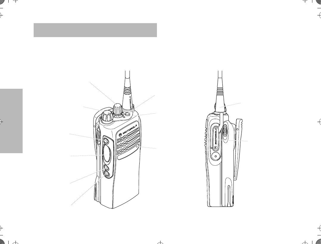
RADIO OVERVIEW
This user guide covers the operation of the ATS 2500
Portable Radio.
Please read the ÒSafety InformationÓ on pages 61 to
64
before
using this radio.
2. On-Off / Volume Knob
9. Microphone
4. Push to Talk (PTT)
8. LED Indicator
5. Side Button 2
6. Side Button 3
1. Mode Selector Knob
7. Top Button
10. Antenna
Connector
11. Dust Cover
Button
covering
Accessory
3. Side Button 1/
Model I
Select Key
ATS2500
.
book Page 4 Monday
,
December 18
,
2000 7:39 PM
RADIO OVERVIEW
5
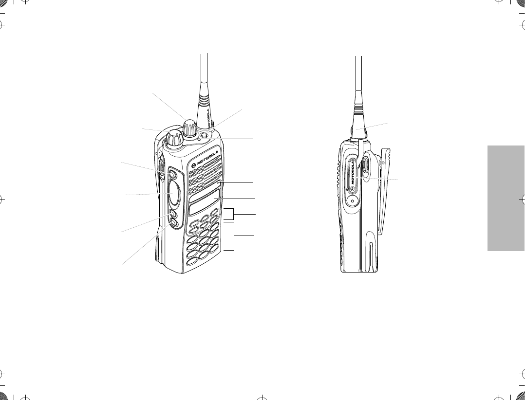
OPERATION AND CONTROL FUNCTIONS
Radio Controls
Refer to the illustrations above and on the previous
page.
1. Mode Selector Knob
Used to select the required operation mode.
2. On-Off / Volume Knob
Used to turn the radio on or off, and to adjust
the radioÕs volume.
12. LCD Screen
9. Microphone
14. Keypad
13. Menu Keys
3. Side Button 1/
4. Push to Talk (PTT)
8. LED Indicator
5. Side Button 2
6. Side Button 3
1. Mode Selector Knob
7. Top Button
11. Dust Cover
10. Antenna
Connector
2. On-Off / Volume Knob
Button
covering
Accessory
Model II
Select Key
ATS2500
.
book Page 5 Monday
,
December 18
,
2000 7:39 PM
RADIO OVERVIEW
6
3. Side Button 1/Select Key (programmable)
Recommended for the Monitor Button. Also
functions as the select key when programming
your radioÕs lists.
4. Push to Talk (PTT) Button
Press and hold down this button to talk, release
it to listen.
5. Side Button 2 (programmable)
6. Side Button 3 (programmable)
7. Top Button (programmable)
Recommended as Emergency button.
8. LED Indicator
The indicator LED on top of the radio indicates
radio operating conditions.
9. Microphone
Speak clearly into the microphone when send-
ing a message.
10. Antenna
11. Accessory Connector
Connects headsets, remote speaker/micro-
phones and other accessories. Replace
attached dust cover when not in use.
Additionally
for keypad radios (Model II), there are
12. LCD Screen
13. Menu Keys
14. Keypad
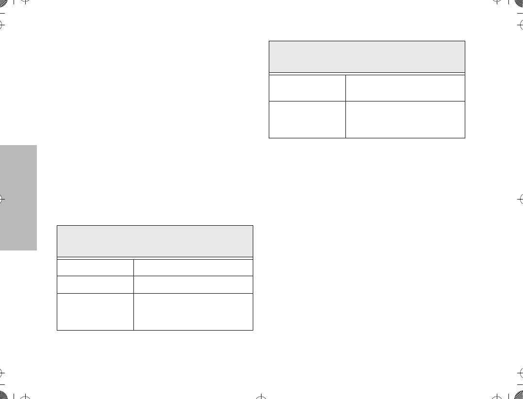
With PTT switch pressed (radio
transmitting)
Continuous red LED Normal transmission.
LED unlit Radio is not transmitting.
Blinking red light
Low battery (conventional mode
only; programmable from the
CPS)
With PTT switch released (radio
receiving)
Blinking red light Mode busy (conventional mode
only).
Blinking green light
Receipt of a telephone call, Pri-
vate Conversation call, or Call
Alert page.
ATS2500
.
book Page 6 Monday
,
December 18
,
2000 7:39 PM
RADIO OVERVIEW
7
Programmable Buttons
Several of your radio buttons can be programmed (by
using the Customer Programming Software Ñ CPS)
to activate the radio features.
Programmable buttons are
¥ Top button
¥ Three side buttons
Check with your dealer or Motorola representative for a
complete list of the functions your radioÕs
programmable buttons support.
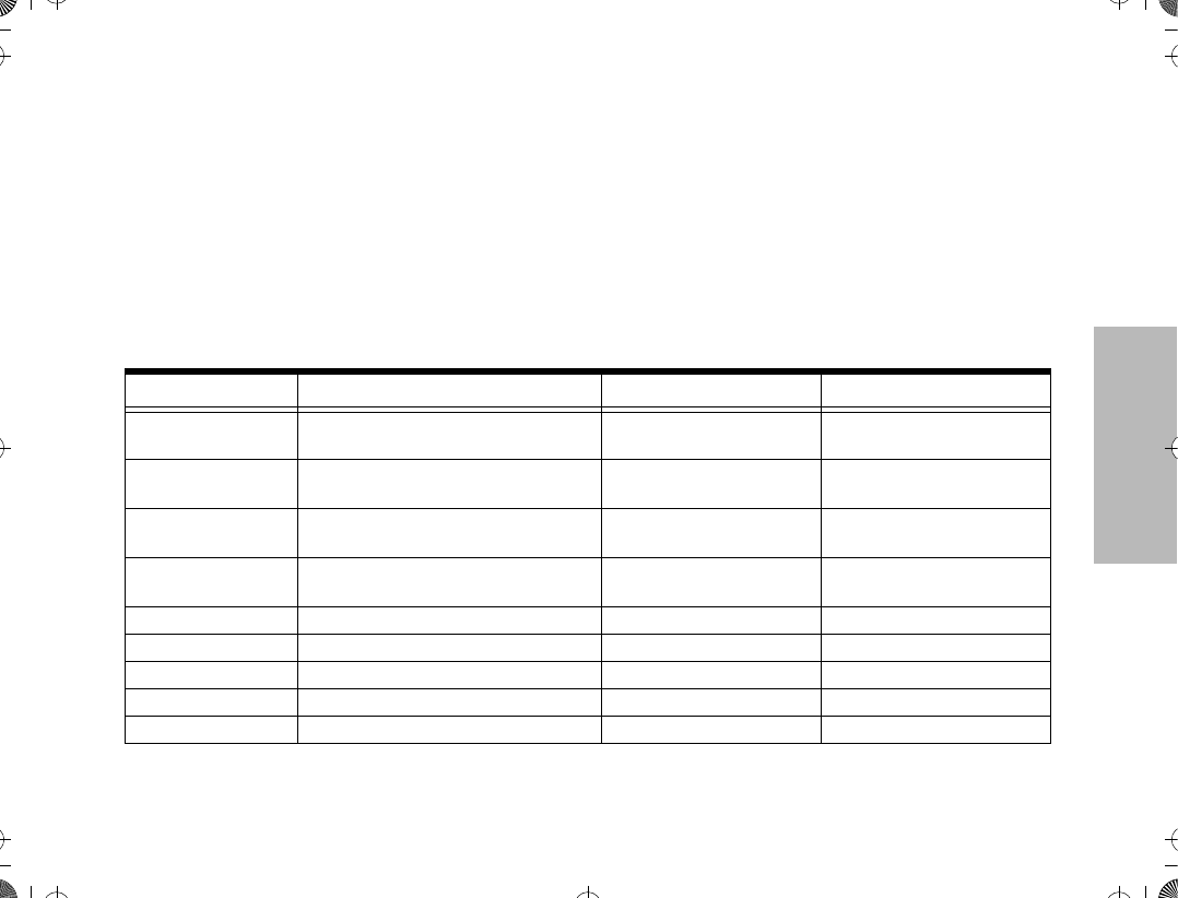
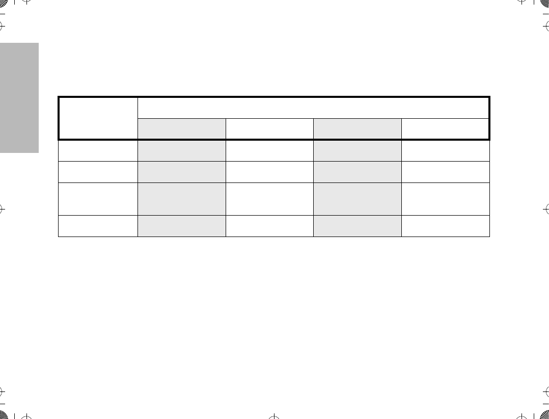
The table below shows the functions available by
¥
short press
- quickly pressing and releasing the
programmable buttons, or
¥
long press
- pressing and holding the
programmable buttons for a period of time
before releasing, or
¥
hold down
- pressing and holding down the
programmable buttons while checking status or
making adjustments.
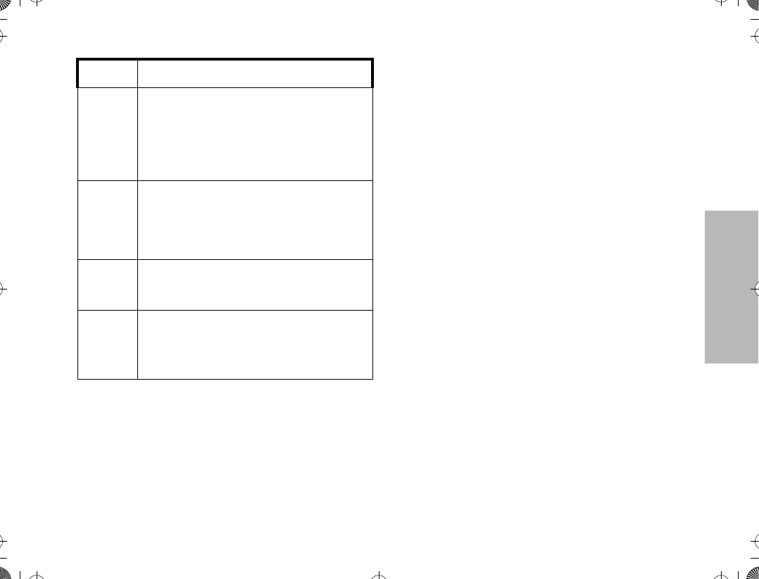
Button Short Press Long Press Hold Down
Monitor/Permanent
Monitor ÑContinually monitors the
selected channel.
Monitors the selected
channel for any activity.
Volume Set Ñ Ñ Sounds a tone for adjusting
the radioÕs volume level.
Scan Toggles between the start/stop of the
Scan operation. Ñ Ñ
Nuisance Delete Temporarily deletes an unwanted
non-priority active scan member. Ñ Ñ
Search Makes a system search.
Light Turns on/off your radioÕs backlight. Ñ Ñ
Emergency Enters Emergency mode. Leaves Emergency mode. Ñ
Call Enters or exits a Private call.
Page Enters or exits a Call Alert.
ATS2500
.
book Page 7 Monday
,
December 18
,
2000 7:39 PM
RADIO OVERVIEW
8
Keypad Keys (for Model II radios only)
These keys are used when dialing a phone number,
making a radio call or entering information for
programming the radioÕs lists.
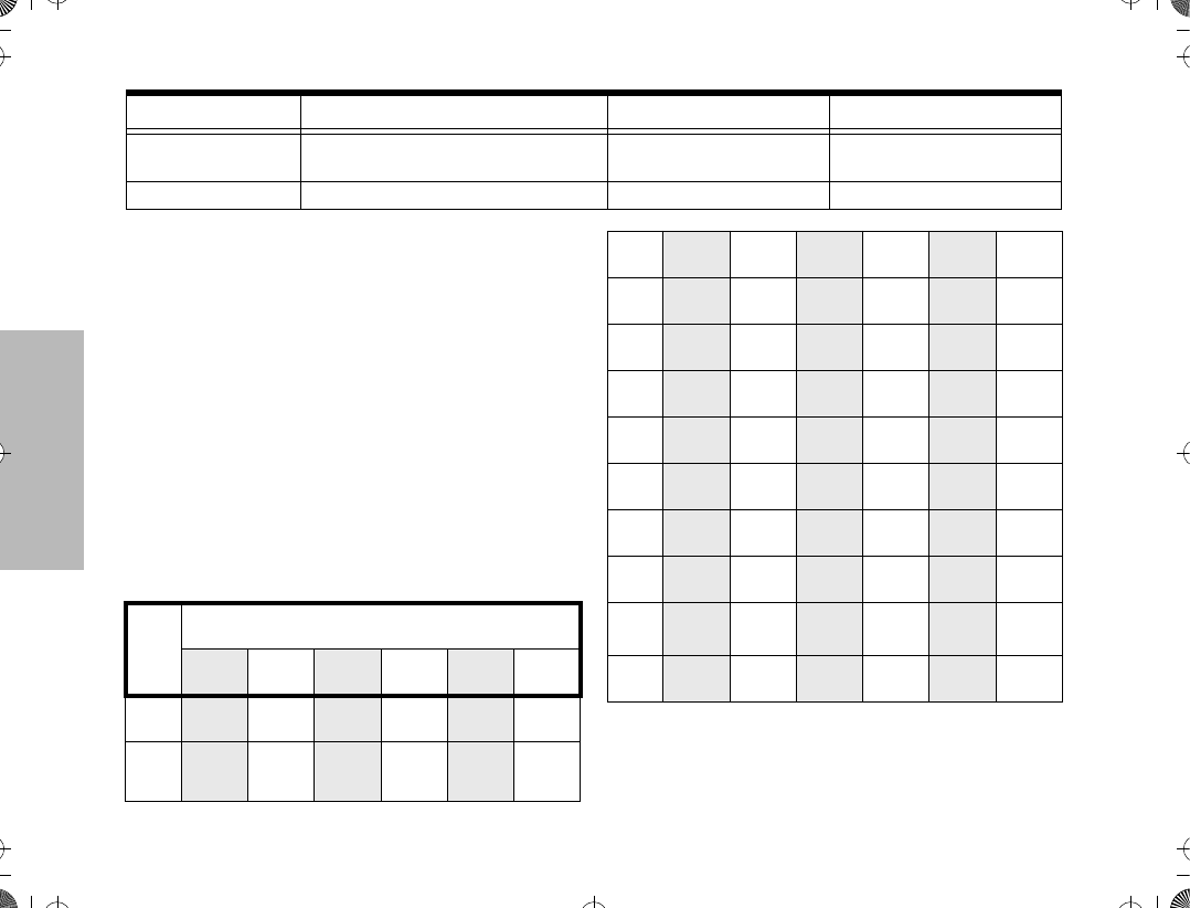
The following table shows the character cycle for each
key, when entering information for programming the
radioÕs lists.
Note:
The sequence in the table above is valid
when entering information on a blank display.
However, when editing existing information, the
above sequence may differ. For instance, if the
Call Response Respond to or exit from a Private
Call or Call Alert. Ñ Ñ
Phone Enters or leaves Phone mode. Ñ Ñ
Button Short Press Long Press Hold Down
Key
Number of Times the Key is Pressed
1 2 3 4 5 6
0
0
1
1
Blank
space
123
456
789
*0#
2
A B C 2
3
D E F 3
4
G H I 4
5
J K L 5
6
M N O 6
7
P Q R S 7
8
T U V 8
9
W X Y Z 9
*
*
#
# - + . / \
ATS2500
.
book Page 8 Monday
,
December 18
,
2000 7:39 PM

RADIO OVERVIEW
9
last character entered is a Ò
R
Ó, pressing
7
to enter the next character, would start the char-
acter cycle at Ò
S
Ó and
NOT
at Ò
P
Ó.
¥
When editing existing information, pressing
1
would
ALWAYS
start the character cycle at
the Ò
blank space
Ó and
NOT
at Ò
1
Ó.
Menu Keys (for Model II radios only)
Selecting a Feature
A unique feature of your radio is its use of the display
to give you quick access to many of the radioÕs
features without having to have a dedicated key for
each feature.
The names of the features (CALL, MUTE, etc.) are
shown on the display, three at a time. Selection of
features is controlled by the three keys directly below
the feature names: the left key controls the left feature,
the middle key controls the middle feature, and the
right key controls the right feature.
Softkeys (l;l)
When already in Menu Mode, these keys are used to
make Menu selections.
Left and Right Arrow Keys (,/)
The left and right arrow keys are used to scroll the
display forward or backward through the radioÕs
features and lists. There is no end point to the list, so if
you continue to scroll in one direction, the display will
Òwrap aroundÓ back to the beginning of the list. If you
hold either key down, the display will scroll at a faster
rate until the key is released.
The left arrow key is also used for editing when you are
entering information manually from the keypad.
Pressing the left arrow key, when editing numeric
information (such as telephone numbers), will
backspace, and erase the display, one character at a
time. If you have erased all the digits, an additional
press of the left arrow key will return the display to the
pre-programmed list.
Pressing the left arrow key, when editing alphabetic
information (such as memberÕs names), will move the
cursor one step to the left.
HOME Key (.)
The HOME key will always return you to the home
(default) display. In most cases, this is the current
mode. In addition, if you are using a feature that
l;l
, . /
Softkey 1 Softkey 3
Left Home Right
Softkey 2
ATS2500
.
book Page 9 Monday
,
December 18
,
2000 7:39 PM
RADIO OVERVIEW
10
requires it, pressing the HOME key will also cause
information to be saved in memory before going to the
home display. Some radio features will automatically
go to the home display when they are completed,
without having to press the HOME key, thus reducing
the number of key presses required.
Menu Display
The menu items can be displayed in normal video or in
reversed video (programmable through the CPS). All
the menu items in the examples in this manual are
shown in reversed video.
The order in which the menu items are displayed is
programmable. Thus, the order of the menu items on
your radio may differ from those shown here in this
manual. In such a situation, press the relevant softkey
to make your menu selections. All descriptions of
functions and displays after the selection are valid.
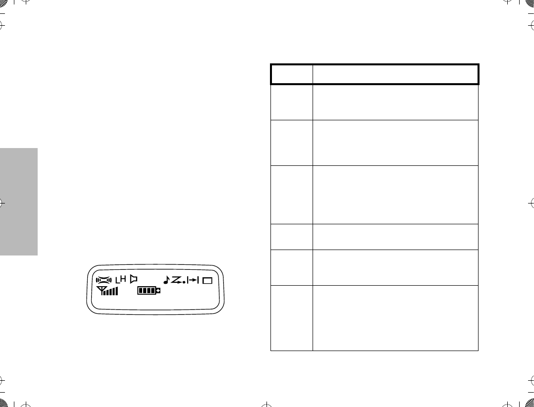
LCD Screen and Icons
Displays mode selected, channel, menu, and radio
status information. The top two screen rows show
radio status indicator symbols, explained in the
following table.
Symbol Name and Description
A
XPANDª Indicator
Indicates that your radio has the companding
feature activated.
B
Power Level Indicator
R lights up when your radio is conÞgured to
transmit in Low Power. S lights up when your
radio is conÞgured to transmit in High Power.
C
Carrier Squelch Indicator
Indicates when the active conventional mode is
being monitored in the carrier squelch mode;
ON = BEING MONITORED/
OFF = NOT BEING MONITORED.
FCall Received
Flashes when a call or page is received.
G
Scan Indicator
Indicates when the radio is scanning;
ON = SCANNING/OFF =NOT SCANNING.
H
Priority Scan
The presence of a dot along with the scan
annunciator indicates the receiving of a priority
mode;
BLINKING DOT = PRIORITY 1
SOLID DOT = PRIORITY 2.
ATS2500
.
book Page 10 Monday
,
December 18
,
2000 7:39 PM
RADIO OVERVIEW
11
Alert Tone Indications
Your radio generates a number of audible tones to
indicate radio operating conditions:
¥Low Battery Ð A low-battery condition is indi-
cated by a high-pitched, cricket-like Òchirp-chirpÓ
when the PTT switch is released following a
transmission.
¥Successful Power-Up Ð A short, medium-pitched
tone when the radio is Þrst turned on indicates
that the radio has passed its power-up self test
and is ready for use.
¥ Unsuccessful Power-Up Ð A short, low-pitched
tone when the radio is Þrst turned on indicates
that the radio has failed its power-up self test
and is not ready for use. Contact your service
representative for service.
¥ Transmit on Receive-Only Mode Ð If you press
the PTT switch while tuned to a Òreceive-onlyÓ
mode, you will hear a continuous, low-pitched
alert tone, indicating that no transmission is pos-
sible on this mode. This tone will continue until
the PTT switch is released.
¥ Transmit Inhibit on Busy Mode Ð If you press the
PTT switch while the mode is busy, you will hear
a continuous, low-pitched alert tone, indicating
that no transmission is possible on this mode.
This tone will continue until the PTT switch is
released.
¥ Transmit Inhibit on Flat Battery Ð If you press the
PTT while the battery is ßat, you will hear a con-
tinuous, low pitched alert tone, indicating that
transmission is impossible.
¥ Invalid Mode Ð A continuous, low-pitched tone is
heard when an invalid or unprogrammed opera-
tion is attempted on the radio.
J
Direct
Indicates whether you are talking directly to
another radio (talkaround), or through a
repeater;
ON = DIRECT
OFF = REPEATER.
K
Programming/Viewing Mode
Indicates when the radio is in the programming
or viewing mode;
ON = IN VIEWING MODE
BLINKING = IN PROGRAMMING MODE.
M
Signal Quality Indicator
Shows the radio signal quality. Five bars
indicates the best signal (Smart Zone Only).
P
Battery Level Indicator
Shows the remaining charge in your battery,
based on how many bars are displayed.
Flashing, indicates ßat battery.
Symbol Name and Description
ATS2500
.
book Page 11 Monday
,
December 18
,
2000 7:39 PM

RADIO OVERVIEW
12
¥ Valid (Good) Key Press Ð A short, medium-
pitched tone when a keypad key is pressed indi-
cates that the key press was accepted.
¥ Invalid (Bad) Key Press Ð A short, low-pitched
tone when a keypad key is pressed indicates
that the key press was rejected.
¥ Emergency Alarm Entry Ð A short, medium-
pitched tone when the emergency button is
pressed indicates that the radio has entered the
emergency mode.
¥ Emergency Alarm/Call Exit Ð A continuous,
medium-pitched tone when the radio is in the
emergency mode indicates that the radio has
exited the emergency mode.
¥ Failsoft (Trunked Systems Only) Ð A faint Òbeep-
ingÓ tone every ten seconds indicates that the
radio is operating in the failsoft mode.
¥ Time-Out Timer Warning Ð Your radioÕs time-out
timer limits the length of your transmission time.
When you are pressing the PTT switch (transmit-
ting), a short, low-pitched warning tone will
sound four seconds before the allotted time will
expire.
¥ Time-Out Timer Timed-Out Ð If you hold down
the PTT switch longer than the time-out timerÕs
allotted time, a continuous, low-pitched tone will
sound, indicating that your transmission has
been cut off. This tone will continue until the PTT
switch is released.
¥ Phone Busy Ð A Òbah-bah-bah-bahÓ tone when
telephone interconnect is accessed indicates
that all available modes are busy and the radio is
in queue for the next available phone line.
¥ Call Alertª (Page) Received Ð A group of four
medium-pitched tones every Þve seconds indi-
cates that your radio has received a Call Alert
page.
¥ Call Alertª (Page) Sent Ð A single medium-
pitched tone (central acknowledge), followed by
a group of four medium-pitched tones indicates
that a Call Alert page sent by your radio has
been received by the target radio.
¥ Private Conversationª Call Received Ð A group
of two medium-pitched tones indicates that your
radio has received a Private Conversation call.
This sequence is repeated every Þve seconds
for approximately 20 seconds for enhanced Pri-
vate Conversation.
¥ Trunked System Busy (Trunked Systems Only) Ð
A Òbah-bah-bah-bahÓ tone when a trunked sys-
tem is accessed indicates that all available chan-
nels are busy and the radio is in queue for the
next available channel.
¥ Call Back (Trunked Systems Only) Ð A group of
three medium-pitched tones (di-di-dit) indicates
that a talkgroup is now available for your previ-
ously requested transmission.
ATS2500
.
book Page 12 Monday
,
December 18
,
2000 7:39 PM

GETTING STARTED
13
GETTING STARTED
BATTERY INFORMATION
Battery Care and Tips
This product is powered by a nickel-cadmium (NiCd),
nickel-metal-hydride (NiMH), or lithium-ion
rechargeable battery.
The following battery tips will help you obtain the
highest performance and longest cycle life from your
Motorola rechargeable battery.
¥Charge your new battery overnight (14-16
hours) before using it to obtain maximum
battery capacity and performance.
¥ Charging in non-Motorola equipment may lead
to battery damage and void the battery warranty.
¥ When charging a battery that is attached to the
radio, turn the radio off to ensure a full charge.
¥ The battery should be at about 25¡C (room
temperature) whenever possible. Charging a
cold battery (below 10¡C) may result in leakage
of electrolyte and ultimately, in failure of the
battery.
¥ Charging a hot battery (above 35¡C) results in
reduced discharge capacity, affecting the
performance of the radio. Motorola rapid-rate
battery chargers contain a temperature-sensing
circuit to ensure that the battery is charged
within these temperature limits.
¥ New batteries can be stored up to two years
without signiÞcant cycle loss. Store new/unused
batteries in a cool dry area.
¥ Batteries which have been in storage should be
charged overnight.
¥ Do not return fully charged batteries to the
charger for an Òextra boostÓ. This action will
signiÞcantly reduce cycle life.
¥ Do not leave your radio and battery in the
charger when not charging. Continuous charging
will shorten battery life. (Do not use your charger
as a radio stand.)
¥ For optimum battery life and operation use only
Motorola brand chargers. They were designed to
operate as an integrated energy system.
ATS2500
.
book Page 13 Monday
,
December 18
,
2000 7:39 PM
GETTING STARTED
14
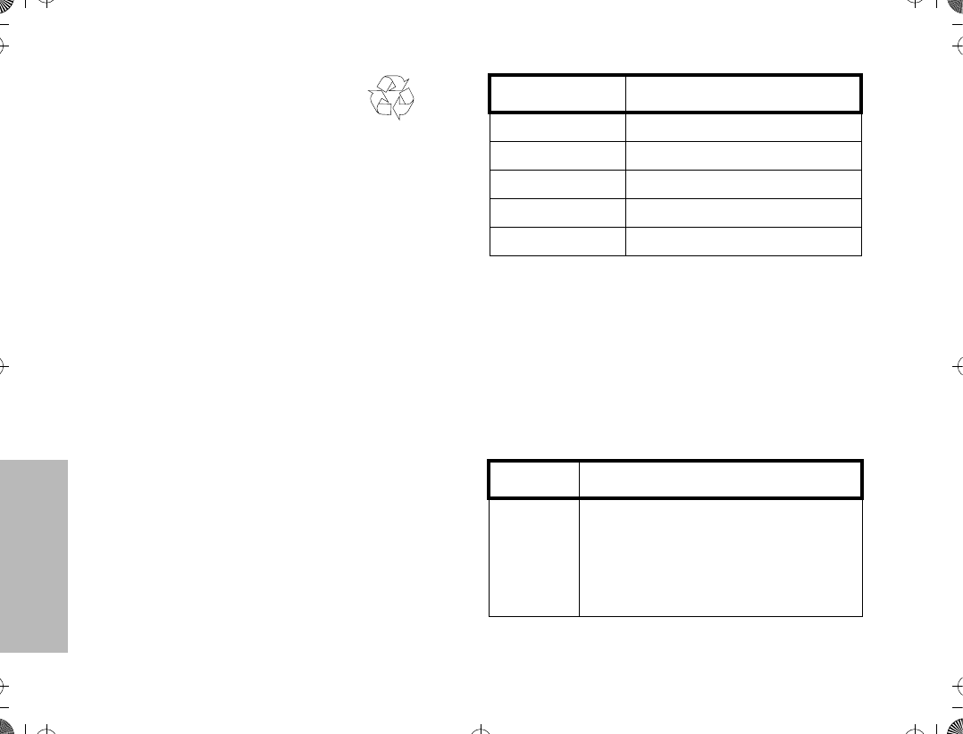
Recycling or Disposal of Batteries
At the end of its useful life, the NiCd battery can be
recycled. However, recycling facilities may not be
available in all areas.
Motorola endorses and encourages the recycling of all
re-chargeable batteries. Contact your local Motorola
dealer for further information.
Charging the Battery
If a battery is new, or its charge level is very low,
indicated by battery level indicator showing one or no
segments, you will need to charge the battery before
you can use it in your radio.
Note:Batteries are shipped uncharged from
the factory. New batteries could
prematurely indicate full charge, charge
a new battery for 14-16 hours before
initial use.
1. Place the radio with the battery attached, or the
battery alone, in the charger.
2. The chargerÕs LED indicates the charging
progress.
Battery chargers will charge only the Motorola
authorized batteries listed below; other batteries will
not charge.
FM - Factory Mutual
NiCd
Charger LED Status
Red Battery is charging
Green Battery is fully charged
Flashing Red * Battery is unchargeable
Flashing Yellow Charger is getting ready to charge
Flashing Green Battery is 90% charged
* Battery is damaged. Please contact your dealer.
Part No. Description
HNN9008
HNN9009
HNN9010
HNN9011
HNN9012
HNN9013
High-Capacity NiMH
Ultra-High-Capacity NiMH
Ultra-High-Capacity FM NiMH
High-Capacity FM NiCd
High-Capacity NiCd
Lithium-Ion
ATS2500
.
book Page 14 Monday
,
December 18
,
2000 7:39 PM
GETTING STARTED
15
ACCESSORY INFORMATION
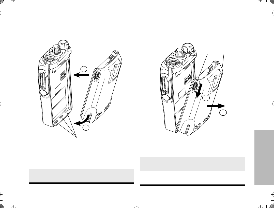
Attaching the Battery Removing the Battery
1. Fit the extensions at the bottom of the
battery into the slots at the bottom of the
radioÕs body.
2. Press the top part of the battery towards the
radio until you hear a click.
1
2
Slots
1. Turn off the radio, if it is turned on.
2. Slide the battery latches, on both sides of
the battery, downwards.
3. Pull the top part of the battery away from the
radioÕs body, and remove the battery.
3
2
Battery
Latches
ATS2500
.
book Page 15 Monday
,
December 18
,
2000 7:39 PM
GETTING STARTED
16
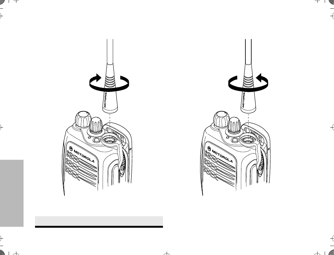
Attaching the Antenna Removing the Antenna
¥ Turn the antenna counterclockwise until you can
remove it.
1. Align the threaded end of the antenna with
the radioÕs antenna connector.
2. Turn the antenna clockwise to fasten it.
ATS2500
.
book Page 16 Monday
,
December 18
,
2000 7:39 PM
GETTING STARTED
17
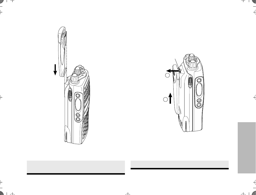
Attaching the Belt Clip Removing the Belt Clip
1. Align the grooves of the belt clip with those
of the battery.
2. Press the belt clip downwards until a click is
heard.
1. Use a key to press the belt clip tab away
from the battery.
2. Slide the belt clip upwards to remove it.
2
1
Belt Clip Tab
ATS2500
.
book Page 17 Monday
,
December 18
,
2000 7:39 PM
GETTING STARTED
18
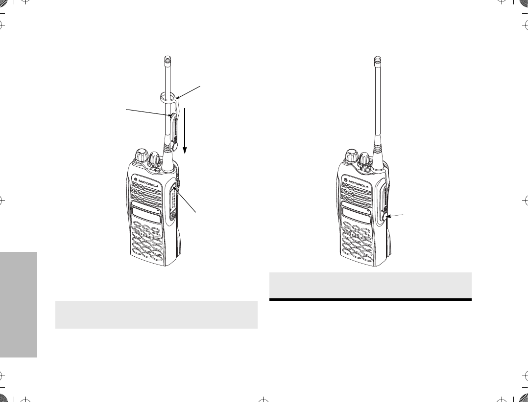
Attaching the Dust Cover
1. Place the dust cover loop over the attached
antenna.
2. Slide the loop all the way down to the base
of the antenna.
3. Insert the dust cover tab into the slot above
the connector.
Dust Cover
Loop
Dust Cover
Tab
Slot for
Dust Cover Tab
4. Tighten the thumbscrew to hold the cover in
place. DO NOT overtighten the thumbscrew.
Thumbscrew
ATS2500
.
book Page 18 Monday
,
December 18
,
2000 7:39 PM
GETTING STARTED
19
RADIO OPERATION
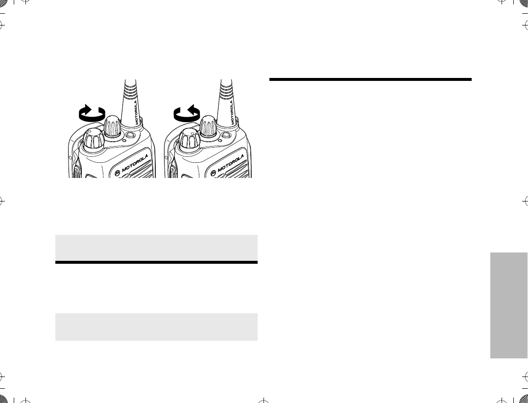
Turning The Radio On or Off
Adjusting the RadioÕs Volume
Radio Self Test
Turn the radio on by rotating the volume control
clockwise. The radio goes through a power-up self
check and, if it passes the check, the display
momentarily shows ÒSELF TEST.Ó A good-power-up,
high-pitched tone sounds to indicate that the radio has
passed the self check.
If the radio fails the self check, the display shows
ÒERROR XX/XXÓ (where XX/XX is an alphanumeric
error code), accompanied by a bad-power-up, low-
pitched tone. Turn the radio off, check the battery, and
turn the radio back on. If the radio still does not pass
the self check, a problem exists in the radio. Contact
your nearest Motorola Service Shop.
Note: The power-up self check veriÞes that the
radioÕs microprocessor-based systems are work-
ing, but it does not check all of the rf compo-
nents, nor does it check the operation of all
customer-speciÞc features. Motorola recom-
mends that the functionality of the radio be peri-
odically checked by an authorized Motorola
service shop.
To turn the radio on, turn the On-Off/Volume Con-
trol knob clockwise.
To turn the radio off, turn the On-Off/Volume Con-
trol knob counterclockwise until you hear a click.
Turn the On-Off/Volume Control knob to adjust
the volume level.
Listen until you hear a transmission, then adjust
the volume control for a comfortable listening level.
ON OFF
Or, if a button is programmed for Òvolume set,Ó
press this button and adjust the volume to a com-
fortable listening level.
ATS2500
.
book Page 19 Monday
,
December 18
,
2000 7:39 PM
20
BASIC RADIO CALLS
BASIC RADIO CALLS
This section outlines the basic functions of your radio.
All references to what is shown on the display is only
valid for Model II radios. Throughout this section, the
display below
is used to indicate the radioÕs home display.
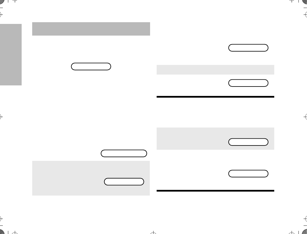
SELECTING A ZONE AND MODE
A mode is a channel or talkgroup and all the features
that are programmed to it. A zone is a grouping of
modes that is selected using the menu keys. Before
you use your radio to receive or send messages, you
should Þrst select the desired zone and mode.
Selecting a Zone
(for Model II radios only)
Selecting a Mode
1. Press / until
ZONE is displayed.
2. Press l (the soft-
key below ZONE).
The current zone
name blinks on the
display.
For example
PLANT POLICE
ZONE MUTE CALL
PLANT POLICE
3. Press / until the
desired zone name is
displayed.
ÑorÑ
Enter the number of
the desired zone.
For example
4. Press ..
5. The displayed zone is
the new selected
zone.
1. Turn the mode selector knob to the desired
mode.
2. The display shows
the selected modeÕs
name.
For example
3. If the selected mode
is unprogrammed, an
invalid-mode tone is
heard until a valid
programmed mode is
selected.
CITY POLICE
CITY POLICE
PLANT MODE 1
UNPROGRAMMED
ATS2500
.
book Page 20 Monday
,
December 18
,
2000 7:39 PM

21
BASIC RADIO CALLS
RECEIVING A CALL
MAKING A CALL
Conventional Modes
Note: Do not interrupt another user. If the present
mode is programmed to receive PL, ensure that
the mode is not in use by pressing the monitor
button to listen for activity.
¥If the mode-busy feature is enabled, a blink-
ing red LED on receive (PTT released) indicates
that the mode is currently busy.
¥If a mode is programmed for receive only,
any attempt to transmit on that mode will cause
an invalid-mode tone to sound until the PTT
switch is released.
Trunked Modes
Note: If you hear a busy signal (a low-frequency
Òbah-bah-bah-bahÓ), release the PTT switch and
wait for a call-back tone (sounds like Òdi-di-ditÓ).
When you hear the call-back tone you will have
three seconds to press the PTT switch. This
allows you to make another call without getting a
busy signal.
1. Turn the radio on and select the desired
zone and mode (see Selecting a Zone and
Mode).
2. Your radio is now set to receive calls on the
selected mode.
1. Turn the radio on and select the desired con-
ventional zone and mode (see Selecting a
Zone and Mode).
2. Press and hold the PTT switch on the side of
the radio and speak slowly and clearly into
the microphone area. The red LED lights
continuously when the radio is transmitting.
3. When you have Þnished talking, release the
PTT to listen.
1. Turn the radio on and select the desired
trunked zone and mode (see Selecting a
Zone and Mode).
2. Press and hold the PTT switch on the side of
the radio and speak slowly and clearly into
the microphone area. The red LED lights
when the radio is transmitting. When you
have Þnished talking, release the PTT to lis-
ten.
ATS2500
.
book Page 21 Monday
,
December 18
,
2000 7:39 PM

22
BASIC RADIO CALLS
¥If a continuous talk-prohibit tone is heard
when the PTT switch is pressed, transmission is
not possible. The radio may be out of range.
Low-Battery Alert
Your radio emits an alert tone when a low-battery
condition is detected.
Coded Squelch Operation
Tone Private-Line¨ (PL), Digital Private-Lineª (DPL),
and carrier squelch operation are all available in your
radio, on a per-mode basis. When in carrier squelch
operation, all trafÞc on the mode is heard. When in PL
or DPL operation, your radio responds to only those
messages intended for you. When this feature is
mode-slaved, PL, DPL, or carrier squelch is
programmed to each mode.
Whenever the radio is operating in carrier squelch, the
display will show C.
Variable RF Power Level
(Selected Models Only)
Radios can have more than one power level. High
power can be programmed on modes where high
power is permitted, and low power can be
programmed on all other modes. The high-/low-power
feature can be selected via the menu keys.
FAILSOFT OPERATION
(TRUNKED SYSTEMS ONLY)
The ÒfailsoftÓ system ensures continual radio
communications capability during a trunked system
failure. Your radio will automatically go into failsoft
operation, if the central trunking controller fails for any
reason. While in failsoft operation, your radio will
transmit and receive on a predetermined frequency on
a conventional mode. When the trunked system
returns to normal operation, the radio will automatically
leave the failsoft operation and return to trunked
operation.
During failsoft operation,
1. You will hear a faint
ÒbeepingÓ sound
every ten seconds.
Alternates between
and
2. Your radio becomes unsquelched.
FAILSOFT
PLANT POLICE
ATS2500
.
book Page 22 Monday
,
December 18
,
2000 7:39 PM
23
BASIC RADIO CALLS
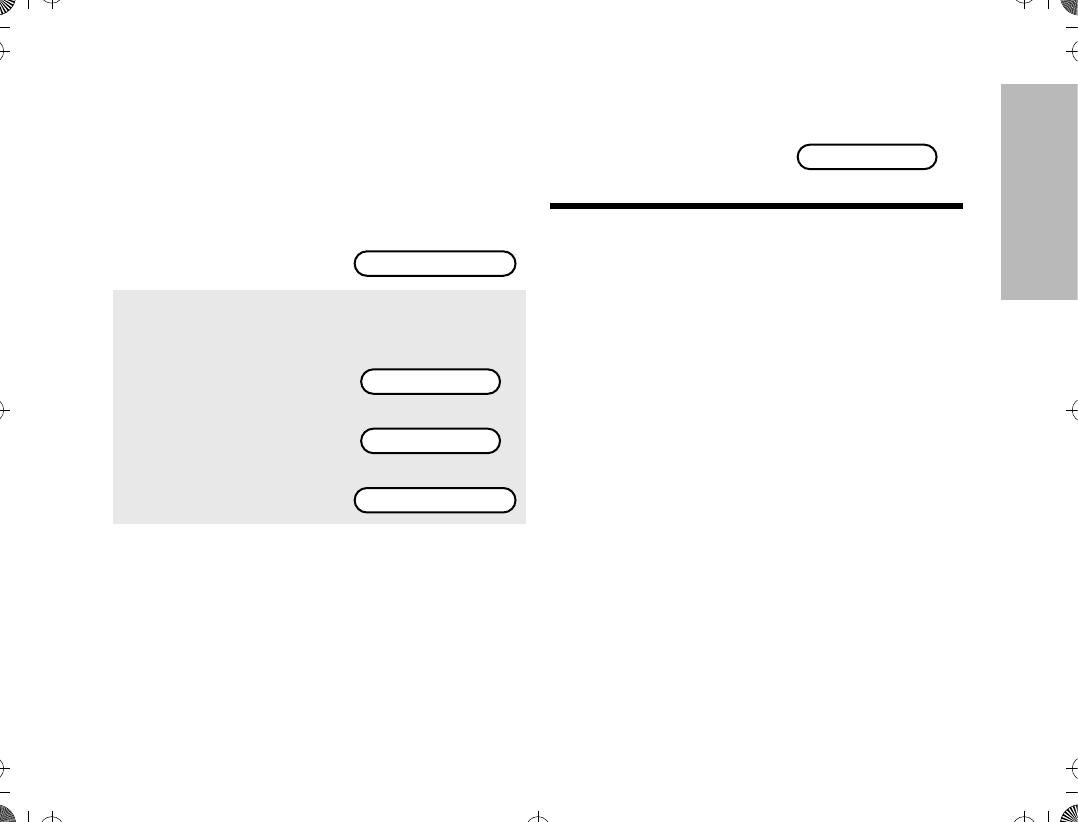
MUTING THE KEYPAD TONES
(FOR KEYPAD RADIOS ONLY)
The radioÕs keypad tones, normally heard each time a
keypad key is pressed, can be turned off (muted) or on
(unmuted) at your discretion. To use the keypad mute
feature
Note: Pressing . or the PTT switch will exit this
menu without changing the mute selection.
1. Press / until
MUTE is displayed.
2. Press ; (the soft-
key below MUTE).
You will see the cur-
rent mute state
momentarily.
or
Then
ZONE MUTE CALL
TONES ON
TONES OFF
ON OFF
3. Press the softkey
below the desired
mute state (on or off).
The radio returns to
the home display.
PLANT POLICE
ATS2500
.
book Page 23 Monday
,
December 18
,
2000 7:39 PM
24
TRUNKED FEATURES
TRUNKED FEATURES
This section outlines the trunked features of your radio.
All references to what is shown on the display is only
valid for Model II radios. Throughout this section, the
display below
is used to indicate the radioÕs home display.
VIEWING YOUR RADIOÕS ID NUMBER
To view your radioÕs ID number
Note: If your radio has been so programmed, you
can press the call button for quick access to
viewing your radioÕs ID number. This takes you
directly to step 3.
ENHANCED PRIVATE CALL OPERATION
The Enhanced Private Conversation feature not only
allows you to have a conversation that is heard only by
the two parties involved, but also enables you to
determine whether the radio that you are calling is in
service. The radio being called can also view the
calling radio's ID number before answering. You can
then choose whether or not to leave your radioÕs ID
number (via a Call Alert page) with the radio you are
calling so that you may be called back. Enhanced
Private Conversation operation is similar to telephone
operation.
Answering a Private Call
1. Press / until CALL is
displayed.
2. Press l (the softkey below CALL).
3. The display shows the
last ID number transmit-
ted or received.
4. Press ,.
5. The display shows your
radioÕs ID number.
6. Press . to return the
radio to the home dis-
play.
PLANT POLICE
ZONE MUTE CALL
ID: 722588
MY ID:741317
PLANT POLICE
1. Upon receiving a Pri-
vate Conversation call,
two alert tones sounds
(repeating every Þve
seconds for 20 sec-
onds).
Alternates between
and
CALL RECEIVED
PLANT POLICE
ATS2500
.
book Page 24 Monday
,
December 18
,
2000 7:39 PM
25
TRUNKED FEATURES
Note: If you press the PTT switch before you press
the call response button, the response will be
transmitted to everyone in the talkgroup (a dis-
patch mode operation).
¥After answering a Private Call, the callerÕs ID
number is stored in your radio as the Òlast ID
number receivedÓ.
¥If your radio is conÞgured for Private Call II,
upon receiving a Private Conversation call, two
alert tones sounds, followed by the received
voice.
Making a Private Call
There are four phases in making a private call, namely
¥initiating a private call,
¥ entering the desired radio ID number,
¥ sending the radio ID number, and
¥ having the conversation and hanging-up.
Initiating a Private Call
2. The green LED and call received status
annunciator, F, will blink indicating that a call
is being received. You have 20 seconds to
answer the call before the radio automatically
returns to the home display.
3. Press the call response button or the call but-
ton.
4. The display shows the
incoming callerÕs ID
number, and the call
received annunciator will
turn off.
5. After viewing the callerÕs ID number, you can
decide to either talk privately (go to next step),
or not answer the call by pressing the call
response or call button to return to the home
display.
6. If you decide to answer the call, press the PTT
switch.
7. The callerÕs ID number
remains displayed for the
duration of the call.
8. When Þnished with conversation, press .
or the call response button to hang up.
ID: 722588
ID: 722588
9. The radio will return to
the home display.
1. Press / until CALL is
displayed.
2. Press l (the softkey below CALL).
PLANT POLICE
ZONE MUTE CALL
ATS2500
.
book Page 25 Monday
,
December 18
,
2000 7:39 PM
26
TRUNKED FEATURES
Entering the Desired Radio ID Number
If the last ID number called is the desired number, go
directly to step 5.
To enter a new number
Note: Exactly six digits must be entered for the
radio ID number. If fewer than six digits were
entered, you will hear a bad-keypress tone and
the display will show ÒINVALID ENTRYÓ when
attempting to send the radio ID number. A bad-
keypress tone will also be heard if you try to
enter a seventh digit.
¥Once you have started entering numbers,
the , key functions as a backspace key.
Pressing it causes the last digit entered to be
erased, and the cursor moves to the left. When
the last digit is erased, an additional press of this
key causes the last ID number transmitted or
received to be displayed; pressing / shows
the Þrst member of the list.
To enter a number from the call list
To enter a number from a location in the call list
3. The display shows the
last ID number transmit-
ted or received.
4a. Enter the new six-digit ID number using the
keypad.
4b. On the display, the old ID number disappears
and the new digits appear as they are being
entered.
4c. The cursor ßashes indicating the location of
the next number to be entered.
ID: 722588
4a. Press either , or /.
4b. / takes you forward to the Þrst or next
member of the list; , takes you backwards
to the last or previous member of the list.
4c. When at a member of
the list, the display alter-
nates between showing
the memberÕs name and
ID number.
Alternates between
and
4a. Press either , or / to enter the call
list.
4b. Enter the Þrst digit of the location number. If
there are fewer than 10 members in the list,
go directly to step 4e.
CK TANG
ID: 784116
ATS2500
.
book Page 26 Monday
,
December 18
,
2000 7:39 PM
27
TRUNKED FEATURES
Note: The last member of the list is also the Òlast ID
transmitted or receivedÓ at position Ò00Ó on the
list.
¥If you enter a location number that does not
exist (for example, Ò15Ó), the display will show
ÒINVALID ENTRY,Ó and the radio will sound an
invalid-keypress tone and return back to step 4b
of this procedure.
Sending the Radio ID Number
Note: If the radio you are calling is not in service,
you will not hear the ringing and the display will
show ÒNO ACKÓ. Go to step 10 to hang up.
¥If your radio is conÞgured for Private Call II,
you will not hear the telephone type ringing.
Instead you are able to proceed to talk to the
Called party.
Having the Conversation and Hanging-up
4c. If there are 10 or more members in the list,
the display shows ÒID LOC#X_Ó (where X is
the Þrst digit). The cursor blinks to show the
location of the second digit.
4d. Enter the second digit of the location number.
4e. The radio goes to that
position in the list. The
display alternates
between showing the
memberÕs name and ID
number.
Alternates between
and
5. Press the PTT switch to transmit the ID num-
ber.
6. If the radio you are calling is on the air, you will
hear a telephone-type ringing for 20 seconds,
or until the called radio answers the call.
CK TANG
ID: 784116
7. If the party you are call-
ing does not answer the
call within twenty sec-
onds, the telephone ring-
ing stops and an alert
tone sounds.
At this point you can either send a Call Alertª
page, or go to step 10 to hang up.
8. If the party you are calling answers the call,
you will hear his/her voice.
9. Press the PTT switch to have a Private Con-
versation with the called person.
10. When Þnished with your conversation, or if the
radio you called does not answer or is not in
service, press . to hang up.
NO ANSWER
ATS2500
.
book Page 27 Monday
,
December 18
,
2000 7:39 PM

28
TRUNKED FEATURES
Note: Once engaged in a private conversation, if
the radio is left idle for more than one minute, a
momentary warning alert sounds every six sec-
onds to remind you that dispatch calls are not
being heard. After two minutes, a permanent
invalid mode tone sounds.
Leaving a Call Alert Page
CALL ALERT OPERATION
Answering a Call Alert Page with a Group
Call
Note: When you received a Call Alert page, you
can enter Private Call mode and call the paging
radio using the latest ID received.
11. The radio will return to
the home display.
1. If the party you want to have a Private Call
does not answer the call within twenty sec-
onds, you can choose to leave a Call Alertª
page. This leaves your radioÕs ID number with
the called radio so you can be called back
later.
2. Press the PTT switch to send the Call Alert
page. You will hear Þve beeps, indicating that
the system has received your ID number and
the radio you are calling is on the air.
3. Press ..
4. The radio will return to
the home display.
PLANT POLICE
PLANT POLICE
1. Upon receiving a Call Alert page, four alert
tones sounds (repeats every 5 seconds).
2. The green LED lights and the Call Received
annunciator, F, blinks indicating a call is
received.
3. Press the PTT switch to answer the page.
4. The display shows the
current talkgroup. The
audible alert, LED and
call received annunciator
turns off.
5. The ID number of the radio that paged you is
stored as Òthe last ID number received.Ó
6. Have your conversation in the normal manner;
all members of your talkgroup will hear your
response. Press the PTT switch to talk;
release the switch to listen.
FIRE DEPT
ATS2500
.
book Page 28 Monday
,
December 18
,
2000 7:39 PM

29
TRUNKED FEATURES
Making a Call Alert
There are three phases in making a call alert, namely
¥initiating a call alert,
¥ entering the radio ID number that you wish to
page, and
¥ sending the call alert.
Initiating a Call Alert
Note: The same list is shared by both Call Alert
and Private Conversation features.
¥If your radio has been so programmed, you
can press the page button for quick access to
the Call Alert feature. This will take you directly
to step 3.
Entering the Radio ID Number that you
wish to Page
If the last ID number called or received is the desired
number, go directly to step 5.
To enter a new number
Note: Exactly six digits must be entered for the
radio ID number. If fewer than six digits were
entered, you will hear a bad-keypress tone when
attempting to send the radio ID number. A bad-
keypress tone will also be heard if you try to
enter a seventh digit.
¥Once you have started entering numbers,
the , key functions as a backspace key.
Pressing it causes the last digit entered to be
erased, and the cursor moves to the left. When
the last digit is erased, an additional press of this
key causes the last ID number transmitted or
received to be displayed; pressing / shows
the Þrst member of the list.
To enter a number from the call list
1. Press / until PAGE is
displayed.
2. Press l (the softkey below PAGE).
3. The display shows the
last ID number transmit-
ted or received.
PAGE PHON VIEW
ID: 722588
4a. Enter the new six-digit ID number using the
keypad.
4b. On the display, the old ID number disappears
and the new digits appear as they are being
entered.
4c. The cursor ßashes indicating the location of
the next number to be entered.
4a. Press either , or /.
ATS2500
.
book Page 29 Monday
,
December 18
,
2000 7:39 PM
30
TRUNKED FEATURES
To enter a number from a location in the call list
Note: The last member of the list is also the Òlast ID
transmitted or receivedÓ at position Ò00Ó on the
list.
¥If you enter a location number that does not
exist (for example, Ò15Ó), the display will show
ÒINVALID ENTRY,Ó and the radio will sound an
invalid-keypress tone and return back to step 4b
of this procedure.
Sending the Call Alert
4b. / takes you forward to the Þrst or next
member of the list; , takes you backwards
to the last or previous member of the list.
4c. When at a member of
the list, the display alter-
nates between showing
the memberÕs name and
ID number.
Alternates between
and
4a. Press either , or / to enter the call
list.
4b. Enter the Þrst digit of the location number. If
there are fewer than 10 members in the list,
go directly to step 4e.
4c. If there are 10 or more members in the list,
the display shows ÒID LOC#X_Ó (where X is
the Þrst digit). The cursor blinks to show the
location of the second digit.
4d. Enter the second digit of the location number.
CK TANG
ID: 784116
4e. The radio goes to that
position in the list. The
display alternates
between showing the
memberÕs name and ID
number.
Alternates between
and
5. Press the PTT switch to transmit the ID num-
ber.
CK TANG
ID: 784116
ATS2500
.
book Page 30 Monday
,
December 18
,
2000 7:39 PM
31
TRUNKED FEATURES
If the page is unsuccessful
If the page is successful
AUTOMATIC MULTIPLE SITE SELECTION
(AMSS)
The automatic multiple site selection (AMSS) feature
extends communications beyond the reach of a single
trunked site. In a system where wide-area coverage is
required, multiple trunking sites are used.
AMSS automatically switches the radio to a different
site when the current-site signal becomes too weak.
Typically, this happens when the radio is moved out of
the range of one site and into the range of another.
Under normal conditions, this switching is invisible to
the user.
Viewing the Current Site
6a. If you hear one beep, the ID number has
been received by the system, but the radio
you are paging is not on the air; your radio
remains in the Call Alert mode.
If after six seconds the called radio fails to
acknowledge the alert, a low-pitched alert
tone sounds and the display changes to ÒNO
ACKNOWLEDGEÓ.
6b. Press the PTT switch to send the ID number
again, or press . to hang up and return to
the home display.
6a. If you hear Þve beeps, the ID number has
been received by the system, and the radio
you are paging is on the air and has received
your page.
6b. The radio automatically
returns to the home dis-
play
PLANT POLICE
1. Press the search button.
2. If the radio is locked on a
site, the display shows
the current site.
3. If the radio is scanning
for a new site, the dis-
play shows ÒSCAN-
NINGÓ until it locks on a
new site.
Then it shows the num-
ber of the new site.
SITE 4
SCANNING SITE
SITE 7
ATS2500
.
book Page 31 Monday
,
December 18
,
2000 7:39 PM
32
TRUNKED FEATURES
Forcing a Site Change Locking and Unlocking a Site
1. Press and hold down the search button to
force the change to a new site.
2. You will hear a tone
while the radio scans for
a new site.
3. The radio automatically
returns to the home dis-
play.
SCANNING SITE
PLANT POLICE
1. Press / until SITE is
displayed.
2. Press l (the softkey below SITE).
3. The current lock state is
momentarily displayed. or
4. The display changes to
5. Press the key below the desired lock state.
6. The radio automatically
returns to the home dis-
play.
SITE PAGE CALL
SITE LOCKED
SITE UNLOCKED
LOCK UNLK
PLANT POLICE
ATS2500
.
book Page 32 Monday
,
December 18
,
2000 7:39 PM
33
CONVENTIONAL
FEATURES
CONVENTIONAL FEATURES
This section outlines the conventional features of your
radio. All references to what is shown on the display is
only valid for Model II radios. Throughout this section,
the display below
is used to indicate the radioÕs home display.
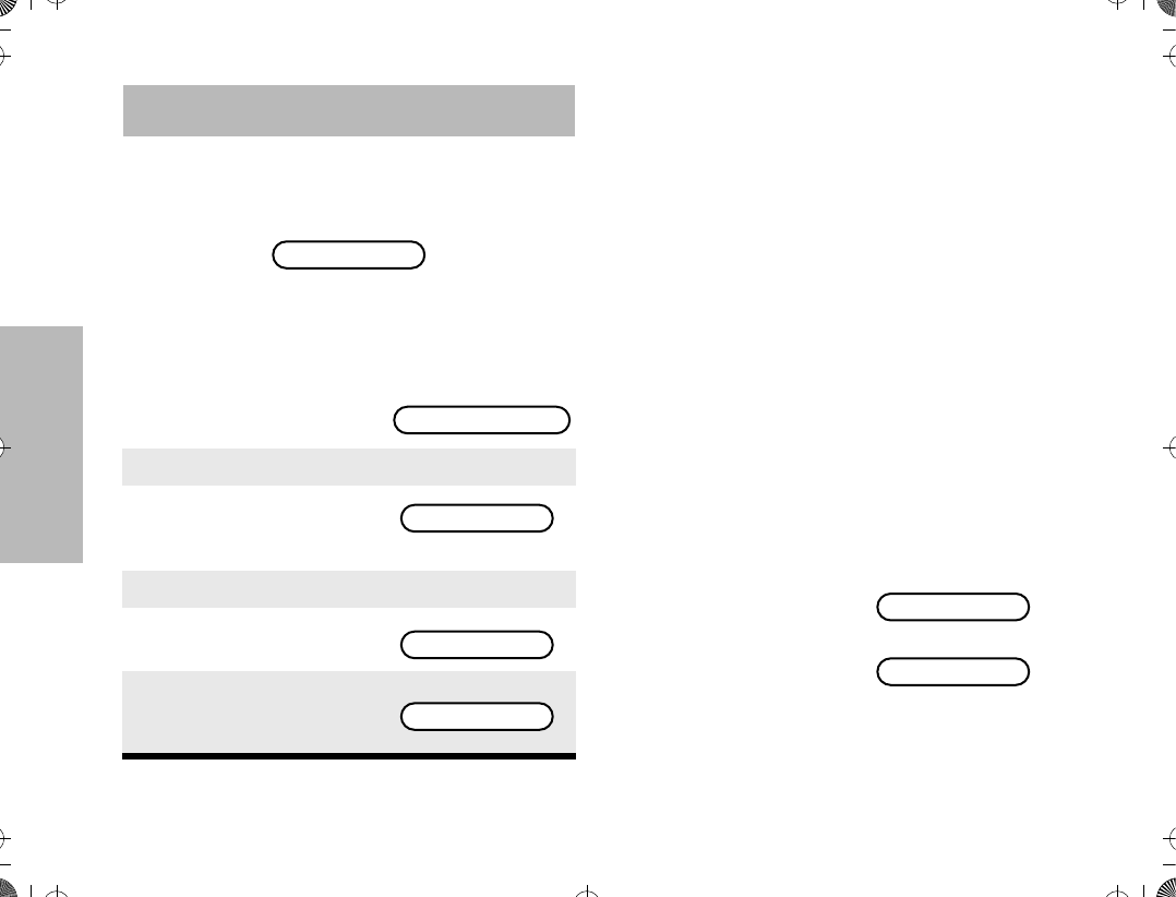
REPEAT/DIRECT
The repeat/direct feature allows you to bypass the
repeater and talk directly to another portable radio.
This is known as DIRECT operation. The transmit
frequency is the same as the receive frequency.
¥In REPEAT operation, you talk through the
repeater, which increases the radio's operating
range. The transmit frequency is not the same
as the receive frequency.
¥ If the repeat/direct feature is programmed to a
mode, that mode operates on either direct or
repeat operation.
¥ If the repeat/direct feature is programmed to the
keypad, you can change the repeat/direct setting
by doing the following.
SMART PTT
Smart PTT is a per-mode feature which gives the
system manager better control of radio operators.
When smart PTT is enabled in your radio, you cannot
transmit on an active mode. Three radio-wide
variations of smart PTT are available.
¥Transmit Inhibit on Busy ModeÑyou are pre-
vented from transmitting if any activity is
detected on the mode.
1. Press / until DIR is
displayed.
PLANT POLICE
DIR PWR PROG
2. Press l (the softkey below DIR).
3. The current talkaround
state appears on the dis-
play for a few seconds. or
4. Then, the display
prompts for the new
state.
5. Press l below the desired talkaround
state: repeat (RPTR) or direct (DIR).
6. The radio returns to the
home display.
REPEATER MODE
DIRECT MODE
DIR RPTR
PLANT POLICE
ATS2500
.
book Page 33 Monday
,
December 18
,
2000 7:39 PM

34
CONVENTIONAL
FEATURES
¥Transmit Inhibit on Busy Mode with Wrong
Squelch CodeÑyou are prevented from trans-
mitting on an active mode with a squelch code
other than your own. If the PL code is the same
as yours, you are allowed to transmit.
¥Quick-Key OverrideÑThis feature can work in
conjunction with either of the two above varia-
tions. This feature allows you to override the
transmit-inhibit state by quick-keying (two PTT
presses within a programmable period -- the
default is one second -- of each other) the radio.
Note: If you try to transmit (press the PTT) on a
smart PTT mode that is busy, a continuous alert
tone is generated until the PTT is released; the
transmission is inhibited.
¥The red LED blinks when the radio is receiv-
ing indicating that the mode is busy.
ATS2500
.
book Page 34 Monday
,
December 18
,
2000 7:39 PM
35
SCAN
SCAN
This section outlines the scan functions of your radio.
All references to what is shown on the display is only
valid for Model II radios. Throughout this section, the
display below
is used to indicate the radioÕs home display.
SCAN OPERATION
The scan feature allows you to monitor activity on
different conventional or trunked modes by scanning a
scan list of modes. This list can be programmed with
the Customer Programming Software (CPS) or user
programmable.
Three types of scan operation are available depending
on radio model.
Your radio may support both priority and non-priority
scanning. With priority scanning enabled, a scan list
can have one mode assigned as the Þrst priority mode,
and a second as the second priority mode.
Automatic scanning (autoscan) can be programmed
through the CPS. If autoscan is enabled for a mode,
your radio begins scanning, using the modeÕs scan list,
whenever you select that mode. The radio will continue
autoscanning until you select a mode that does not
have autoscan enabled.
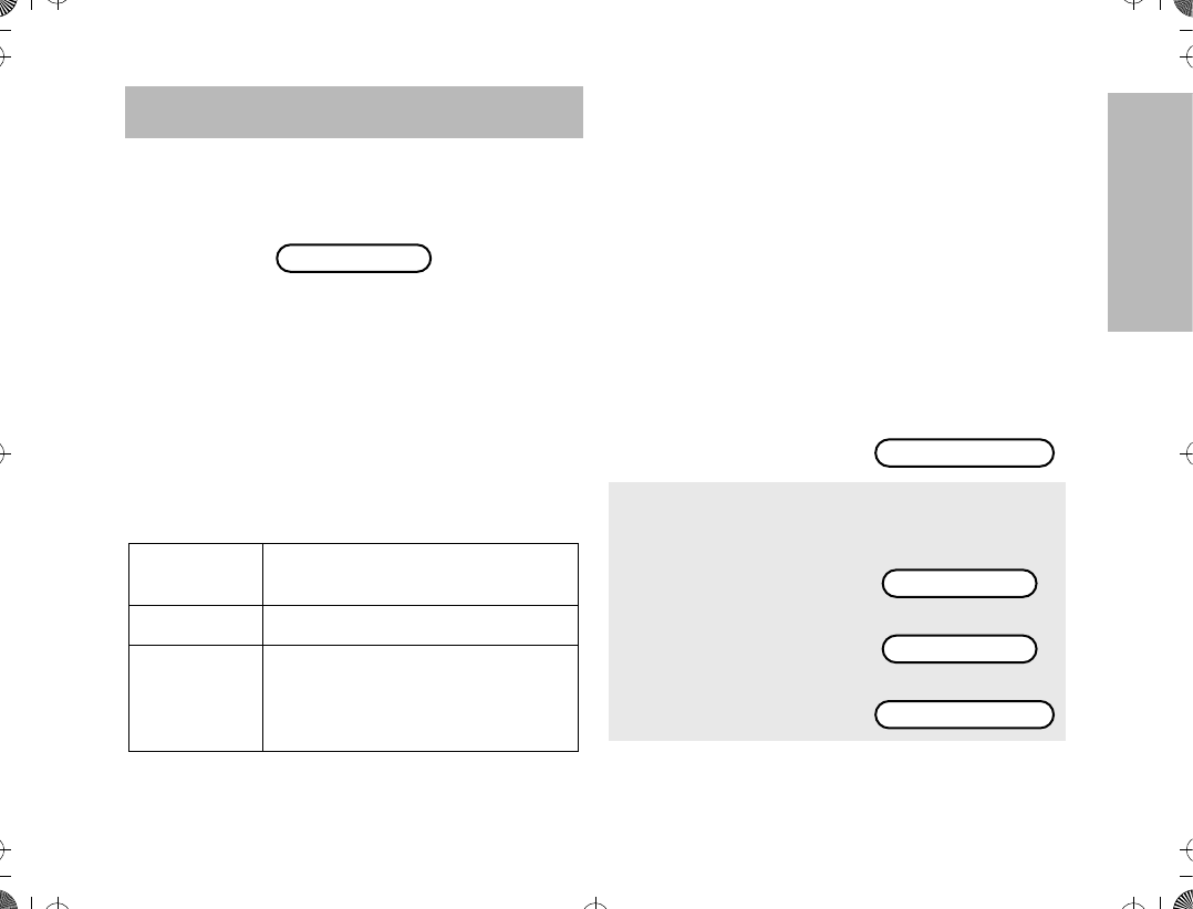
Turning Scan On or OFF with the Keypad
(for Keypad radios only)
Trunking
Priority Monitor
Comprises modes that are all from the
same trunked system.
Conventional Comprises conventional-only modes.
Talkgroup
Scan
Comprises conventional modes and
trunked modes from more than one
trunking system. Priority operation is
NOT available in this type of list.
PLANT POLICE
1. Press / until
SCAN is displayed.
2. Press ; (the soft-
key below SCAN).
You will see the cur-
rent scan state
momentarily.
or
Then
PHON SCAN CALL
SCAN ON
SCAN OFF
ON OFF
ATS2500
.
book Page 35 Monday
,
December 18
,
2000 7:39 PM
36
SCAN
Note: The scan status annunciator, G, is dis-
played when the scan operation is active. It will
be removed from the display when the scan
operation is terminated.
Deleting Nuisance Modes
When the radio scans to a mode you do not wish to
monitor (nuisance mode), you can temporarily delete
that mode from the scan list.
Note: Priority modes cannot be deleted.
Viewing a Scan List
(for keypad radios only)
The view scan list feature allows you to view the
members of the scan list associated with the currently
selected mode.
To view a scan list
3. Press the softkey
below the desired
scan state (on or off).
The radio returns to
the home display.
1. When your radio is locked on the mode to be
deleted, press the nuisance-mode delete
button (programmed via the CPS).
2. A valid-keypress chirp is heard, indicating
that the mode has been deleted.
3. The radio continues scanning the remaining
modes in the list.
4. To resume scanning the deleted mode, you
must leave and reenter scan operation.
PLANT POLICE
1. Press / until
VIEW is displayed.
2. Press l (the soft-
key below VIEW).
3. Press ; (the soft-
key below SCAN).
The display shows
the Þrst member of
the scan list.
For example
4. Every subsequent press of / will scroll
through subsequent members of the scan
list.
5. To leave the scan list feature, press the
HOME key, or the PTT switch, or turn the
mode selector knob.
6. The radio returns to
the home display.
PAGE STS VIEW
PHON SCAN CALL
FIRE DEPT
PLANT POLICE
ATS2500
.
book Page 36 Monday
,
December 18
,
2000 7:39 PM

37
SCAN
Note: The programming-mode annunciator, K, is
displayed while list view mode is active.
¥The scan status annunciator, G, appears,
indicating that a scan list is being viewed.
¥The dot of the priority scan annunciator, H,
blinks if the current displayed member of the
scan list is a priority 1 mode, and is solid the cur-
rent displayed member of the scan list is a prior-
ity 2 mode.
Programming a Scan List
(for keypad radios only)
The program scan list feature allows you to program
the members of the scan list associated with the
currently selected mode.
To program a scan list Note: The programming-mode annunciator, K,
blinks while program mode is active.
¥The scan status annunciator, G, appears,
indicating that a scan list is being viewed.
¥The dot of the priority scan annunciator, H,
blinks if the current displayed member of the
scan list is a priority 1 mode, and is solid the cur-
rent displayed member of the scan list is a prior-
ity 2 mode.
1. Press / until
PROG is displayed.
2. Press l (the soft-
key below PROG).
3. Press l (the soft-
key below SCAN).
The display shows
the current mode
selected.
For example
PROG
SCAN PHON CALL
FIRE DEPT
4. Use the mode selector knob to select the
required talkgroup zone.
5. Press , or / to select the required
zone. If the scan status annunciator G is
displayed, the mode is part of the scan list.
6. Press the select key to change the scan
mode (see ÒScan ModesÓ on page 38).
7. After making all the changes, select the
required operating mode.
8. Press the HOME key, or the PTT switch, or
turn the mode selector knob to commit all
the changes made.
ATS2500
.
book Page 37 Monday
,
December 18
,
2000 7:39 PM
38
SCAN
Scan Modes
When programming the scan list, each member can
be given one of several scan modes. The following
table lists the scan mode cycle activated by
subsequent presses of the select key.
Note: There can only be ONE Priority 1 member
and ONE Priority 2 member in a scan list. Thus,
if there is already a Priority 1 member in the
scan list, changing another memberÕs mode to
Priority 1, would automatically cause the previ-
ous memberÕs mode to be changed to a Scan
Member. This same behavior is also seen when
programming the Priority 2 member.
Initial Scan
Mode of Member
Number of Times the Select Key is Pressed
1 2 3 4
Priority 2* Priority 1* Non Scan Member Scan Member Priority 2*
Priority 1* Non Scan Member Scan Member Priority 2* Priority 1*
Non Scan
Member Scan Member Priority 2* Priority 1* Non Scan Member
Scan Member Priority 2* Priority 1* Non Scan Member Scan Member
* Priority options are only available if enabled.
ATS2500
.
book Page 38 Monday
,
December 18
,
2000 7:39 PM

39
PROGRAMMING THE
RADIO
PROGRAMMING THE RADIO
This section outlines the programming functions of
your radio, and is only valid for Model II radios.
Throughout this section, the display below
is used to indicate the radioÕs home display.
Programming the
Telephone List Numbers
This feature lets you use the radioÕs keypad to
change the telephone numbers assigned to any of
the telephone list members. Each phone number
can have up to 16 digits.
To change the telephone list
1. Press / until PROG
is displayed.
2. Press l (the softkey
below PROG).
3. Press ; (the softkey
below PHON). The dis-
play shows the Þrst pro-
grammable member of
the telephone list.
PLANT POLICE
PROG
SCAN PHON CALL
FIRE DEPT
4. Press / or ,,
ÑorÑ
Use the keypad to enter the desired memberÕs
position number (1 to 19) to view the other
members of the telephone list.
5. When you stop on a
member of the list, the
display will alternate
between showing the
memberÕs name and
telephone number.
Alternates between
and
6. Press the select key to enter edit mode.
7. A short press would
enable the editing of the
telephone number. The
display shows the cur-
rent memberÕs telephone
number.
8. A long press would
enable the editing of the
memberÕs name. The
display shows the cur-
rent memberÕs name.
POLICE DEPT
5556213
5556213
POLICE DEPT
ATS2500
.
book Page 39 Monday
,
December 18
,
2000 7:39 PM
40
PROGRAMMING THE
RADIO
Note: The programming-mode annunciator, K,
blinks while program mode is active.
¥In the edit mode, the , key functions as a
backspace key. Pressing it will erase the previ-
ous digit, and the cursor will move to the left.
When the last digit on the display has been
erased, additional presses of this key or the
/ key will cause you to leave the edit mode
without making any changes.
¥You can only enter a maximum of 16 digits in
any entry for the telephone list. When this maxi-
mum is reached, the cursor will disappear. If you
try to add any more digits, you will hear an
invalid (bad) keypress alert tone.
Programming the Call List
This feature lets you use the radioÕs keypad to
change the radio ID numbers assigned to the call list
used by the trunked Private Conversationª and
Call Alertª features. Similarly, in Conventional
Mode, you may change the Call List used by Stat-
Alert Selective Call and Call Alert.
To change the call list radio ID numbers
9. Use any of the alphanumeric keys to make the
changes. The blinking cursor indicates the
position of the next number to be added. If you
require a pause in the phone dialing sequence
(to allow for a delay), you can do so by Þrst
pressing the Ò*Ó key, followed by pressing the
Ò#Ó key. The display will show a ÒPÓ for pause.
10. When you have Þnished changing the tele-
phone number, press the select key again. The
change is saved in the radioÕs memory.
11. You are returned to step
5. The display will again
alternate between show-
ing the memberÕs name
and telephone number.
You can now change
additional numbers.
Alternates between
and
12. When you have Þnished making changes,
press . to exit program mode.
13. The radio will return to
the home display.
POLICE DEPT
5556445
PLANT POLICE
1. Press / until PROG
is displayed.
2. Press l (the softkey
below PROG).
3. Press l (the softkey
below CALL). The dis-
play shows the Þrst pro-
grammable member of
the call list.
DIR SCAN PROG
SCAN PHON CALL
SK TAN
ATS2500
.
book Page 40 Monday
,
December 18
,
2000 7:39 PM
41
PROGRAMMING THE
RADIO
Note: The programming-mode annunciator, K,
blinks while program mode is active.
¥In the edit mode, the , key functions as a
backspace key. Pressing it will erase the previ-
ous digit, and the cursor will move to the left.
When the last digit on the display has been
erased, additional presses of this key or the
/ key will cause you to leave the edit mode
without making any changes.
¥When the maximum number of digits for the
radio ID is reached, the cursor will disappear. If
you try to add any more digits, you will hear an
invalid (bad) keypress alert tone.
4. Press / or ,,
ÑorÑ
Use the keypad to enter the desired memberÕs
position number (1 to 19) to view the other
members of the call list.
5. When you stop on a
member of the list, the
display will alternate
between showing the
memberÕs name and
radio ID number.
Alternates between
and
6. Press the select key to enter edit mode.
7. A short press would
enable the editing of the
radio ID. The display
shows the current mem-
berÕs radio ID number.
8. A long press would
enable the editing of the
memberÕs name. The
display shows the cur-
rent memberÕs name.
9. Use any of the alphanumeric keys to make the
changes. The blinking cursor indicates the
position of the next number to be added.
CT CHAN
ID: 753951
ID: 753951
CT CHAN
10. When you have Þnished changing the number,
press the select key again. The change is
saved in the radioÕs memory.
11. You are returned to step
5. The display will again
alternate between show-
ing the memberÕs name
and radio ID number.
You can now change
additional numbers.
Alternates between
and
12. When you have Þnished making changes,
press . to exit program mode.
13. The radio will return to
the home display.
CT CHAN
ID: 753853
PLANT POLICE
ATS2500
.
book Page 41 Monday
,
December 18
,
2000 7:39 PM
42
TELEPHONE
OPERATION
TELEPHONE OPERATION
This section outlines the telephone operations of your
radio. All references to what is shown on the display is
only valid for Model II radios. Throughout this section,
the display below
is used to indicate the radioÕs home display.
The telephone feature allows you to use your radio
similar to a standard telephone.
When you are dialing from the keypad, your radio
may be programmed with either buffered dial (you
enter all digits and press the PTT before the digits
are sent out) or live dial (each digit is sent out as it is
pressed).
Answering a Telephone Call
Note: The call received status annunciator, F,
ßashes when you receive a call, but is not dis-
played when you answer the call.
Making a Telephone Call
(for Model II radios only)
There are three phases in making a phone call,
namely
¥ accessing the telephone system,
¥ sending the telephone number,
¥ having the conversation and hanging-up.
Accessing the Telephone System
1. When a telephone call is
being received, you will
hear telephone-type
ringing.
Alternates between
and
2. Press the pre-pro-
grammed phone button
or call response button
to answer the call.
PLANT POLICE
PLANT POLICE
PHONE CALL
PHONE CALL
3. Carry on with your conversation in the normal
manner. Press the PTT switch to talk; release
the PTT to listen.
4. When you have Þnished your conversation,
press . or the phone button to hang up.
5. The radio will return to
the home display.
1. Press / until PHON
is displayed.
2. Press l (the softkey below PHON).
PLANT POLICE
MSG SCAN PHON
ATS2500
.
book Page 42 Monday
,
December 18
,
2000 7:39 PM
43
TELEPHONE
OPERATION
Sending the Telephone Number
Sending the telephone number using the keypad
Sending the telephone number using a Number on
the Telephone List
3. Your radio attempts to access the telephone
system.
4. If you connect successfully, you will hear a dial
tone.
5. The display will show the
last number dialed.
6a. The number can now be entered from the
keypad, using any of the numeric (0 Ð 9) keys,
and the Ò*Ó and Ò#Ó keys. The cursor ßashes to
indicate the location of the next digit to be
entered. A pause can be entered in the tele-
phone number by Þrst pressing the Ò*Ó key,
then the Ò#Ó key (Buffered dial only - The
pause will be shown on the display as a ÒPÓ).
6b. If your radio is programmed for Òlive dial,Ó each
digit is sent out as its key is pressed.
ÑorÑ
If your radio is programmed for Òbuffered dial,Ó
each digit is temporarily stored as you enter
them. After entering the number, press the
PTT switch to send out the number.
5551135
6c. The telephone number will be sent out; you
will hear tones as they are sent. If you hear a
busy signal, go to step 8 for hang-up proce-
dure.
6a. Press , or /, to enter the telephone
list. / takes you forward to the next mem-
ber of the list; , takes you backwards to
the previous member of the list.
6b. Stop at the member you wish to call.
6c. The display alternates
between showing the
memberÕs name and
telephone number.
Alternates between
and
6d. Press the PTT button.
6e. The telephone number
will be sent out; you will
hear tones as they are
sent.
6f. If you hear a busy signal, go to step 8 for
hang-up procedure.
POLICE DEPT
5556445
POLICE DEPT
ATS2500
.
book Page 43 Monday
,
December 18
,
2000 7:39 PM
44
TELEPHONE
OPERATION
Sending the Telephone number using a Location in
the Telephone List
Having the Conversation and Hanging Up
Note: You can press the pre-programmed phone
button for quick access to the telephone call fea-
ture. This will take you directly to step 3.
¥The ÒPLEASE WAITÓ message is a timed
message. If you cannot access the telephone
system (no dial tone heard), press . key or
the phone button to hang up, and start again at
step 1 of this procedure.
¥If you are out of range of the trunked system
or the phone interconnect is out of service, ÒNO
PHONEÓ is displayed and a continuous low-
pitched tone sounds.
¥If the trunked phone interconnect is in use, a
busy tone sounds and ÒPHONE BUSYÓ is dis-
played.
6a. Press , or /, to enter the telephone
list.
6b. Enter the location (any preprogrammed loca-
tion from 1 through 19) of the number you
wish to call.
6c. The radio will go to the selected location.
6d. The display alternates
between showing the
memberÕs name and
telephone number.
Alternates between
and
6e. Press the PTT button.
6f. The telephone number
will be sent out; you will
hear tones as they are
sent.
6g. If you hear a busy signal, go to step 8 for
hang-up procedure.
POLICE DEPT
5556445
POLICE DEPT
7. If call is answered, communicate in the normal
manner. Press the PTT switch to talk; release
the PTT to listen.
8. When Þnished with your conversation, or if the
number you called is busy or does not answer,
press . or the phone button to send the
hang-up code.
9. The radio will return to
the home display. PLANT POLICE
ATS2500
.
book Page 44 Monday
,
December 18
,
2000 7:39 PM

45
TELEPHONE
OPERATION
¥When the maximum number of digits have
been entered (buffered dial only), the cursor will
disappear.
¥In the edit mode, the , key functions as a
backspace key. Pressing this key erases the last
digit entered, and moves the cursor to the left.
When the last digit on the display is erased,
additional presses of this key causes the last
member of the preprogrammed telephone list to
be displayed; pressing the / key displays the
Þrst member of the list.
¥After reaching the number you are calling,
you may need to dial an extension number
before you can reach your party. Here, enter the
extension number from the keypad or (if so pro-
grammed) use the arrow keys to Þnd the exten-
sion number in the telephone list. If you have live
dial, the number is sent as the keys are pressed.
If you have buffered dial, press the PTT switch
again to send out the extension number.
¥Motorola trunked systems and many conven-
tional telephone patches generate a high-
pitched go-ahead tone when the radio's PTT
switch is released. This is heard by the land-line
party and is an indicator to begin talking.
¥The conventional telephone feature allows
you to use your conventional radio similar to a
standard telephone. To make a call through the
telephone system, your radio must send access
and hangup codes to the system. Unless other-
wise indicated, the conventional telephone sec-
tions in this manual assume that the access and
hangup codes have been programmed into the
radio by the RSS. These codes will then be auto-
matically transmitted.
ATS2500
.
book Page 45 Monday
,
December 18
,
2000 7:39 PM

46
SPECIAL FEATURES
SPECIAL FEATURES
This section outlines some of the special features that
can be conÞgured for your radio. However, not all
models come equipped with these features.
All references to what is shown on the display is only
valid for Model II radios. Throughout this section, the
display below
is used to indicate the radioÕs home display.
EMERGENCY OPERATION
Pressing the top emergency button (for radios with
emergency operation) sends out an emergency signal,
which takes precedence over any other signalling
activity in progress. This emergency signal can take
two forms: emergency alarm and emergency call. Your
radio can have either or both signal types enabled.
¥The emergency alarm feature alerts the dis-
patcher, who is using a special terminal, to an
emergency condition and identiÞes the unit
sending the emergency signal.
¥ The emergency call (radios with trunked emer-
gency operation only) is a type of dispatch oper-
ation which gives your radio priority access.
Emergency call is programmable for either tacti-
cal or non-tactical operation. Tactical emergency
operation places the call to the currently
selected mode; non-tactical operation places the
call to a predetermined emergency mode.
ÒEmergencyÓ signals a critical situation. It should
NEVER be used for any other reason.
Sending an Emergency Alarm
PLANT POLICE
1. Press and hold the
emergency button (the
length of button press
is programmable by
the CPS).
Alternates between
and
2. A short, medium-pitched emergency tone
sounds, indicating entry into emergency
operation.
3. When the trunked emergency alarm is
acknowledged by the central controller, the
radio sounds Þve beeps and the alarm ends.
4. The radio returns to normal operation or, if
enabled in your radio (trunked emergency
call systems only), enters into emergency
call operation.
5. While in emergency call operation, subse-
quent presses of the emergency button will
re-initiate the emergency sequence.
EMERGENCY
PLANT POLICE
ATS2500
.
book Page 46 Monday
,
December 18
,
2000 7:39 PM
47
SPECIAL FEATURES
Sending a Silent Emergency Alarm
Canceling an Emergency Alarm
The alarm can also be canceled (without sounding the
emergency-exit tone) by:
¥pressing the PTT switch (see following note),
¥ turning the radio off, or
¥ receiving an acknowledge from the dispatcher.
Note: Pressing the PTT switch while the radio is in
emergency alarm operation will place the radio
in emergency call operation if emergency call is
enabled.
Sending an Emergency Call
Note: The mode you use during an emergency is
controlled by whether your radio is programmed
for tactical or non-tactical operation. If tactical,
you will be talking to the mode you selected
before entering emergency call; if non-tactical,
you will talk to a preprogrammed emergency
mode.
1. In radios with the silent emergency alarm
option enabled, pressing the emergency but-
ton sends an emergency signal to the dis-
patcher.
2. During the emergency alarm procedure: the
LED will not light, tones will not sound, and the
display will not change.
3. The audio is muted (turned off), and will
remain so until you exit the emergency state.
1. Press the emergency button for more than
11/2 seconds (programmable by the CPS).
2. A medium-pitched emergency-exit tone
sounds until the button is released and the
radio returns to normal operation.
1. Press the emergency
button.
Alternates between
and
2. A short, medium-pitched emergency tone
sounds.
3. Press the PTT switch requesting a priority
mode assignment in the trunked system.
4. While the radio is in emergency call
operation, it operates in the usual dispatch
manner.
EMERGENCY
PLANT POLICE
ATS2500
.
book Page 47 Monday
,
December 18
,
2000 7:39 PM

48
SPECIAL FEATURES
¥If you change modes while in emergency call
operation, the emergency call is moved and con-
tinued on the new mode.
Ending an Emergency Call
It is important that you exit the emergency call mode
when you have Þnished your emergency call.
Emergency with Voice to Follow
This feature (aka Hot Microphone) places your radio in
a transmit mode for a preprogrammed period of time
(programmable by CPS) after the emergency alarm is
activated. During this time period, voice transmissions
can be made without pressing the PTT.
After this transmit time has expired, the unit will revert
back to receive mode. Normal operation resumes, and
the user is required to press PTT for any further
transmissions on that emergency channel.
DYNAMIC REGROUPING
The dynamic regrouping feature allows the dispatcher
to temporarily reassign selected radios, operating in
the same or different trunked modes, to a single
special mode so that they can communicate with each
other. This feature, enabled in each radio via the CPS,
is typically used during special operations. When your
radio has been dynamically regrouped, you will hear a
distinct ÒgurgleÓ tone.
Mode Selection
You will not notice whether your radio has this feature
enabled until a dynamic regrouping is sent by the
dispatcher. If you turn your radio's mode selector knob
to the dynamic regrouping position without being
dynamically regrouped, an invalid-mode tone will be
heard.
You can select the dynamic regrouping position using
the menu on the display (Model II radios only) or using
the mode selector knob. To do this with the mode
selector knob
1. Press the emergency button for more than 1
1/2 seconds (programmable by the CPS).
2. You will hear a medium-pitched emergency-
exit tone until the emergency button is
released, and the radio will return to normal
operation.
1. When your radio is dynamically regrouped,
you will hear a ÒgurgleÓ tone.
2. Your radio is automatically switched to the
dynamic regrouping mode. The display shows
the name assigned to the dynamic regrouping
mode.
ATS2500
.
book Page 48 Monday
,
December 18
,
2000 7:39 PM
49
SPECIAL FEATURES
Note: Until you select the correct mode position,
you will hear a gurgle tone each time you press
the PTT switch, reminding you that you are
transmitting on the dynamic regrouping mode,
not the mode indicated by the position of the
mode selector knob.
Select Enable and Disable
The dispatcher may classify regrouped radios into
either of two categories: select enabled, and select
disabled.
Scan, Phone, and Private Conversation cannot be
selected while the radio is select disabled.
3. Turn the mode selector knob to the dynamic
regrouping position to transmit on the dynamic
regrouping mode.
4. Talk and listen as usual.
5. When the dynamic regrouping is canceled by
the dispatcher:
a. If the mode selector knob is in the dynamic
regrouping position, an invalid-mode tone is
heard until a normal mode is selected.
b. If the mode selector knob is in any other
mode position, the radio will transmit in the
selected mode.
Select
Enabled
These radios are free to make mode
changes to any available mode,
including the dynamic regrouping
mode.
Select Dis-
abled
These radios cannot change modes,
since the dispatcher has speciÞcally
chosen to force the radio to remain in
the dynamic mode.
ATS2500
.
book Page 49 Monday
,
December 18
,
2000 7:39 PM

50
SMARTZONE
OPERATION
SMARTZONE OPERATION
This section outlines the SmartZone operations of your
radio. All references to what is shown on the display is
only valid for Model II radios. Throughout this section,
the display below
is used to indicate the radioÕs home display.
BENEFITS OF SMARTZONETM
Radios that operate in a SmartZone system enjoy the
beneÞts that SmartZone brings over AMSS operation.
Like AMSS, SmartZone is a wide-area coverage
system that allows multiple sites to be operational in
the system. SmartZone brings several enhancements
over AMSS operation, as in the following.
1. Dynamic Site Assignment
Allows the zone controller to dynamically assign
channels at sites where required, as opposed to
bringing up channels at all of the sites as AMSS
systems do.
2. Variable Density Sites
SmartZone allows sites to have varying numbers
of channel resources to accommodate low-density
areas as well as high-density areas.
PLANT POLICE
3. Automatic Site Registration/De-registration
SmartZone radios automatically send in their unit
IDs and current mode selections upon power up,
power down, site switches, mode changes, and
when they exit emergency operation. This allows
the zone controller to know where the radio is at
all times, and what mode the radio has selected.
4. Critical Site Assignment
One or more sites can be designated as critical
sites. This instructs the zone controller to ensure
that every site designated as a critical site must
have available channel resources, before a chan-
nel is given to a radio wishing to be identiÞed as a
critical site user. Otherwise a busy will be sent to
the unit.
5. Busy Override
This feature allows a SmartZone radio to send a
busy override request if a busy is issued. The zone
controller sends a grant even though not all of the
sites may have available channel resources.
ATS2500
.
book Page 50 Monday
,
December 18
,
2000 7:39 PM

51
SMARTZONE
OPERATION
Site Switching in SmartZone
Site Switching in SmartZone mainly uses signal
strength to determine whether or not to switch sites.
Other factors used are the radio's preferred site
selection, and whether the radio is site locked or not.
Because the radio knows the site ID, active control
mode, and the signal strengths of its adjacent sites,
the radio is capable of quickly switching sites.
6. Enhanced Automatic Site Switching
SmartZone radios will use RSSI (received signal
strength indication) to determine if the radio
should switch to another site. This is transparent
to the user. In addition, the zone controller contin-
uously transmits adjacent site information to the
radios, so that the radio, at any time, is able to
quickly switch to the next site that has the highest
RSSI rating. This is an enhancement over AMSS
systems.
7. Preferred Site
SmartZone radios can program certain sites to be
always preferred, most preferred, or least pre-
ferred. This gives the user the ßexibility to keep a
radio on a particular site, regardless of the pres-
ence of a stronger signal from an adjacent site.
This also forces the radio to always look for its pre-
ferred site and use it whenever possible.
8. Site Trunking
If the zone controller loses communication with
any site, that site will revert to what is known as
Òsite trunking.Ó While in this condition, radios are
still able to operate in the trunking mode, but
trunking operations are limited to the site only.
9. Enhanced Failsoft Operation
If a site experiences a complete failure, it will
revert to failsoft operation like today's SMARTNET
system. A SmartZone radio, however, can be pro-
grammed to automatically migrate to the lowest
failsoft frequency programmed in its list of 32 con-
trol modes. The radio will periodically scan the
control mode to check for the presence of a valid
control mode (in case the radio roamed into a site
which is trunking).
ATS2500
.
book Page 51 Monday
,
December 18
,
2000 7:39 PM
52
SMARTZONE
OPERATION
Viewing the Current Site
Forcing a Site Change
Locking and Unlocking a Site
As in an AMSS radio, you can force the radio to stay
locked onto a site, regardless of whether the signal
level of an adjacent site is higher or not. Of course,
locking a radio onto a particular site defeats the
automatic site switching mechanisms of the radio.
However, you can still force the radio to scan to
another site while site locked. The radio automatically
becomes site locked to the next site it Þnds. Refer to
Locking and Unlocking a Site on page 32 to change
the radioÕs locked state.
Preferred Site Selection
SmartZone radios can have up to eight sites that are
individually set as either always preferred, most
preferred, or least preferred. The default value is no
preference. This feature is programmed via the CPS.
1. Press the search button.
a. If the radio is presently locked on a site, the
display shows either the name of the current
site or the site number.
b. If the radio is scanning
for a new site, the dis-
play shows
until it locks onto a new site. This is a timed
display which disappears after a few seconds.
c. If the radio has not
received a site ID, the
radio displays
until either the display times out or the radio
receives the site ID.
1. Press and hold down the search button to
force the change to a new site.
2. You will hear a tone and
the display shows
while the radio scans for a new site.
SCANNING SITE
SITE XX
SCANNING SITE
3. When a new site is found, the new site's name
will be momentarily displayed if it is known,
otherwise SITE XX
ATS2500
.
book Page 52 Monday
,
December 18
,
2000 7:39 PM

53
SMARTZONE
OPERATION
Busy Override
With the introduction of dynamic site assignment,
critical site, and critical user concepts in SmartZone,
the busy processing rules were changed to allow users
to communicate with some of the trunked mode
members instead of waiting for all trunked mode
members in all sites to be available. A busy override
request can be made to request for the grant, even
though one or more non-critical states are busy. Busy
override is not a radio codeplug option but is enabled
or disabled via the SmartZone manager.
After you have requested a mode by pressing the
PTT, and have received a busy indication
Always-Preferred Site
A SmartZone radio always attempts to stay on this
site whenever possible unless the receive signal
strength indication (RSSI) level falls below the
unacceptable level. The radio periodically checks
the RSSI levels of its preferred site(s) to ensure
that it always operates on the best preferred site
(more than one preferred site can be enabled).
Most-Preferred Site
A site marked in this fashion is one level of prefer-
ence below always preferred. The radio attempts
to remain on this site unless an always-preferred
site is determined to have either the same or a
higher RSSI level. The radio always determines
the best most-preferred site and switches to it
whenever possible.
Non-Preferred Site
A radio operating in this site switches sites if an
always preferred or most-preferred adjacent site
with the same or higher RSSI level is discovered.
The radio always determines the best non-pre-
ferred site and switch to it whenever possible.
Least-Preferred Site
A radio operating in this site switches sites if any
of the above site rankings for any adjacent sites
are discovered and their RSSI levels are at least at
the acceptable range. The unit always determines
the best least-preferred site and switch to it when-
ever possible.
1. Release the PTT and press it again. A busy
indication will be received if still busy.
ATS2500
.
book Page 53 Monday
,
December 18
,
2000 7:39 PM

54
SMARTZONE
OPERATION
Site Trunking
Site trunking occurs when a site is no longer able to
participate in wide-area calls controlled by the zone
controller. Radios operating in site trunking can only
communicate with other radios at that site. All trunking
features are still available. The radio will always be
looking for a wide-area trunking site to lock onto if it
roams into range of one.
2. Keep the PTT switch pressed for the amount
of time speciÞed in the codeplug for busy over-
ride delay time (typically about three seconds,
but can range from two to six seconds).
3. After the timer times out, if the PTT is still
pressed, the busy override request is sent.
4. A programmable busy override chirp acknowl-
edgement is heard.
5. If a grant is received, you should note that not
all of the members of the mode are engaged in
the call. You will not be able to determine this.
More sites may join the call, however, if mem-
bers become available at these sites and the
original call is still active.
1. When a site goes into site
trunking, the radio
receives this indication
and displays.
2. The display will alternate between the current
trunked mode and the site trunking display for
as long as the radio remains in site trunking.
3. The radio will not be considered in site trunking
if:
a. The zone controller determines that the site
should no longer be in site trunking and the
radio receives this indication, or
b. the radio is out of range, or
c. the radio enters failsoft operation.
SITE TRUNKING
ATS2500
.
book Page 54 Monday
,
December 18
,
2000 7:39 PM
55
STAT-ALERT
FEATURES
STAT-ALERT FEATURES
This section outlines the Stat-Alert features of your
radio. Stat-Alert is an option which you can enable
for your radio. Please see your dealers for more
information.
All references to what is shown on the display is only
valid for Model II radios. Throughout this section, the
display below
is used to indicate the radioÕs home display.
VIEWING YOUR RADIOÕS ID NUMBER
To view your radioÕs ID number
Note: If your radio has been so programmed, you
can press the call button for quick access to
viewing your radioÕs ID number. This takes you
directly to step 3.
STAT-ALERT VOICE SELECTIVE CALL
OPERATION
This feature provides a convenient way for a
dispatcher to voice page an individual or group.
Voice selective call decode also eliminates the need
for you to listen to trafÞc that is of no concern to you.
This is a per-radio feature, enabled on a per-mode
basis, and available as individual call or group call.
Voice Selective Call is another method of unmuting
a radio other than PL codes. Radios with Voice
1. Press / until CALL is
displayed.
2. Press l (the softkey below CALL).
3. The display shows the
last ID number transmit-
ted or received.
4. Press ,.
5. The display shows the
last Group ID number
transmitted or received.
PLANT POLICE
ZONE MUTE CALL
ID: 1048
GROUP: 105
6. Press ,.
7. The display shows your
radioÕs ID number.
8. Press ,.
9. The display shows your
radioÕs Group ID number.
10. Press . to return the
radio to the home dis-
play.
MY ID:1048
MY GRP:001
PLANT POLICE
ATS2500
.
book Page 55 Monday
,
December 18
,
2000 7:39 PM

56
STAT-ALERT
FEATURES
Selective Call may be programmed to unmute one
of two ways:
1. (OR muting option) upon receiving proper PL
code or a Selective Call, or
2. (AND muting option) upon receiving both
proper PL code and Selective Call
Receiving a Voice Selective Call
Note: After answering a Voice Selective Call, the
callerÕs ID number is stored in your radio as the
Òlast ID number receivedÓ.
¥Two automatic-reset features are available
for voice selective-call. These features reset the
radio to voice selective call when the automatic
reset timer expires.
1. Automatic Reset Without Carrier Override Ñ
The automatic-reset timer will start after the
last voice message is completed, or after the
radio is dekeyed (you released the PTT switch).
2. Automatic Reset With Carrier Override Ñ
When a carrier is detected, the automatic reset
timer will stop; when the carrier is lost, the
automatic-reset timer will start over.
¥Voice selective call automatic reset is can-
celled when the monitor button is pressed, or
when the mode is changed. The automatic-reset
timer is started over if it was running when either
a voice selective call was again decoded or a
successful transmission was completed.
Making a Voice Selective Call
There are four phases in making a Voice Selective
call, namely
¥ initiating a Voice Selective call,
¥ entering the desired radio ID number,
¥ sending the radio ID number, and
¥ having the conversation.
1. When a call is received, the green LED
ßashes, and a one-time, two-beep alert tone is
emitted; on the display, the call-received status
annunciator (F) ßashes. A voice message will
follow.
2. The display shows the
incoming callerÕs ID
number momentarily.
3. Return the radio back to voice selective call
operation by pressing the monitor button, or if
so programmed, the radio can automatically
reset to voice selective call.
4. The radio will return to
the home display.
ID: 2350
PLANT POLICE
ATS2500
.
book Page 56 Monday
,
December 18
,
2000 7:39 PM
57
STAT-ALERT
FEATURES
Initiating a Voice Selective Call
Entering the Desired Radio ID Number
If the last ID number called is the desired number,
go directly to step 5.
To enter a new number
Note: Once you have started entering numbers,
the , key functions as a backspace key.
Pressing it causes the last digit entered to be
erased, and the cursor moves to the left. When
the last digit is erased, an additional press of this
key causes the last ID number transmitted or
received to be displayed; pressing / shows
the Þrst member of the list.
¥If automatic Selective Call is enabled, your
radio will remain in Selective Call until you exit
the mode. If automatic Selective Call is disabled
in your radio, the radio will immediately exit
Selective Call when you release the PTT.
¥In both Selective Call and Call Alert, a * will
match any number in the ID position. For exam-
ple, paging ID 000* will page all IDs from 0000-
0009. Paging **** will page all radios on the sys-
tem.
To enter a number from the call list
1. Press / until CALL is
displayed.
2. Press l (the softkey below CALL).
3. The display shows the
last ID number transmit-
ted or received.
4a. Enter the new four-digit ID number using the
keypad.
4b. On the display, the old ID number disappears
and the new digits appear as they are being
entered.
4c. The cursor ßashes indicating the location of
the next number to be entered.
ZONE MUTE CALL
ID: 2350
4a. Press either , or /.
4b. / takes you forward to the Þrst or next
member of the list; , takes you backwards
to the last or previous member of the list.
4c. When at a member of
the list, the display alter-
nates between showing
the memberÕs name and
ID number.
Alternates between
and
CK TANG
ID: 2350
ATS2500
.
book Page 57 Monday
,
December 18
,
2000 7:39 PM

58
STAT-ALERT
FEATURES
To enter a number from a location in the call list
Note: The last member of the list is also the Òlast ID
transmitted or receivedÓ at position Ò00Ó on the
list.
¥If you enter a location number that does not
exist (for example, Ò15Ó), the display will show
ÒINVALID ENTRY,Ó and the radio will sound an
invalid-keypress tone and return back to step 4b
of this procedure.
Sending the Radio ID Number
STAT-ALERT CALL ALERT OPERATION
Stat-Alert Call Alert is a per-radio feature that
provides a convenient way for the dispatcher to
page you through your radio. This is especially
useful in noisy environments, or when you need to
be away from your radio equipment.
Receiving a Call Alert Page
4a. Press either , or / to enter the call
list.
4b. Enter the Þrst digit of the location number. If
there are fewer than 10 members in the list,
go directly to step 4e.
4c. If there are 10 or more members in the list,
the display shows ÒID LOC#X_Ó (where X is
the Þrst digit). The cursor blinks to show the
location of the second digit.
4d. Enter the second digit of the location number.
4e. The radio goes to that
position in the list. The
display alternates
between showing the
memberÕs name and ID
number.
Alternates between
and
CK TANG
ID: 2350
5. Press the PTT switch to transmit the ID num-
ber. If enabled, an alert tone will sound during
the transmission of the radio ID number. After
the alert tone, you may talk.
1. Upon receiving a Call Alert page, four alert
tones sounds (repeats every 5 seconds).
2. The green LED lights up and the Call
Received annunciator, F, blinks indicating a
call is received.
3. The display will show the Caller ID, and then
alternates between the home display, and
ÒPAGE RECEIVEDÓ.
4. Press the PTT switch to answer the page. You
may have to make a voice selective call, if the
radio that paged you is on selective call mode.
ATS2500
.
book Page 58 Monday
,
December 18
,
2000 7:39 PM

59
STAT-ALERT
FEATURES
Note: The green ßashing LED, alert tone, and
ßashing annunciator will continue until the Call
Alert is acknowledged (press PTT, or press and
release the monitor button).
Making a Call Alert
There are three phases in making a call alert,
namely
¥ initiating a call alert,
¥ entering the radio ID number that you wish to
page, and
¥ sending the call alert.
Initiating a Call Alert
Note: The same list is shared by both Call Alert
and Select Call features.
¥If your radio has been so programmed, you
can press the page button for quick access to
the Call Alert feature. This will take you directly
to step 3.
Entering the Radio ID Number that you
wish to Page
The procedure for entering the Radio ID Number is
exactly the same as the process outlined in the
Select Call section. Please refer to Entering the
Desired Radio ID Number on page 57.
Sending the Call Alert
If the page is unsuccessful
5. The display shows the
current mode. The audi-
ble alert, LED and call
received annunciator
turns off.
6. The ID number of the radio that paged you is
stored as Òthe last ID number received.Ó
1. Press / until PAGE is
displayed.
2. Press l (the softkey below PAGE).
FIRE DEPT
PAGE PHON VIEW
3. The display shows the
last ID number transmit-
ted or received.
4. Press the PTT switch to transmit the ID num-
ber.
5a. If the called radio fails to acknowledge the
alert, a low-pitched alert tone sounds and the
display changes to ÒNO ACKNOWLEDGEÓ.
ID: 2350
ATS2500
.
book Page 59 Monday
,
December 18
,
2000 7:39 PM

60
STAT-ALERT
FEATURES
If the page is successful
PTT-ID
Stat-Alert PTT-ID is a per-mode feature describing
an identiÞcation code transmission that is tied to the
PTT switch. The ID code is automatically sent every
time a voice transmission occurs (that is, the PTT
switch is pressed). When PTT-ID comes before the
voice transmission, you will hear a tone until the ID
transmission is completed; this helps you avoid
talking while the ID code is being transmitted. This
tone can be disabled on a per-radio basis. Also, the
ID code transmission can be programmed to follow
the voice transmission.
RADIO CHECK
This feature allows the dispatcher to determine if a
radio unit is on the air without disturbing the radio
operator. This is a useful tool for the radio dispatcher
to use for routine maintenance checks, or if there is
reason to doubt the availability of a radio unit. When
the dispatcher "checks" for the radio, the radio will
receive the command and automatically
acknowledge it. The transmit (red) LED will light
when the radio sends the acknowledgement.
EMERGENCY OPERATION
Please refer to Emergency Operation on page 46.
5b. Press the PTT switch to send the ID number
again, or press . to hang up and return to
the home display.
5a. If you hear Þve beeps, the radio you are pag-
ing is on the air and has received your page.
5b. The radio automatically
returns to the home dis-
play
PLANT POLICE
ATS2500
.
book Page 60 Monday
,
December 18
,
2000 7:39 PM