Motorola Solutions 89FT7015 IMD SV Hand Held Data Terminal w/ Bluetooth & WLAN User Manual Enhanced IMD Users
Motorola Solutions, Inc. IMD SV Hand Held Data Terminal w/ Bluetooth & WLAN Enhanced IMD Users
Exhibit 8 Users Manual
User Manual
IMD
Intelligent
Mail
Device
Draft Feb 20, 2005
Models
F3124A & F3125A
6802975C55-O
@6802975C55@
ab

i
COMPUTER SOFTWARE COPYRIGHTS
The Motorola products described in this instruction manual may include copyrighted Motor-
ola computer programs stored in semiconductor memories or other media. Laws in the
United States and other countries preserve for Motorola certain exclusive rights for copy-
righted computer programs, including the exclusive right to copy or reproduce in any form
the copyrighted computer program. Accordingly, any copyrighted Motorola computer pro-
grams contained In the Motorola products described in this instruction manual may not be
copied or reproduced in any manner without the express written permission of Motorola.
Furthermore, the purchase of Motorola products shall not be deemed to grant either directly
or by implication, estoppel. or otherwise. any license under the copyrights, patents or patent
applications of Motorola, except for the normal non-exclusive, royalty free license to use
that arises by operation of law in the sale of a product.
EPS – 34440- B
This warranty applies within the fifty (50) United States, the District of Columbia and Can-
ada.
Document Copyrights
No duplication or distribution of this document or any portion thereof shall take place with-
out the express written permission of Motorola. No part of this manual may be reproduced,
distributed, or transmitted in any form or by any means, electronic or mechanical, for any
purpose without the express written permission of Motorola.
Disclaimer
The information in this document is carefully examined, and is believed to be entirely reli-
able. However, no responsibility is assumed for inaccuracies.
Furthermore, Motorola reserves the right to make changes to any products herein to improve
readability, function, or design. Motorola does not assume any liability arising out of the
applications or use of any product or circuit described herein; nor does it cover any license
under its patent rights nor the rights of others.

ii
Commercial Warranty
Limited Warranty
MOTOROLA COMMUNICATION PRODUCTS
I. What This Warranty Covers And For How Long
MOTOROLA INC. (“MOTOROLA”) warrants the MOTOROLA manufactured Com-
munication Products listed below (“Product”) against defects in material and work-
manship under normal use and service for a period of time from the date of
purchase as scheduled below:
Motorola, at its option, will at no charge either repair the Product (with new or recon-
ditioned parts), replace it (with a new or reconditioned Product), or refund the pur-
chase price of the Product during the warranty period provided it is returned in
accordance with the terms of this warranty. Replaced parts or boards are warranted
for the balance of the original applicable warranty period. All replaced parts of Prod-
uct shall become the property of MOTOROLA.
This express limited warranty is extended by MOTOROLA to the original end user
purchaser only and is not assignable or transferable to any other party. This is the
complete warranty for the Product manufactured by MOTOROLA. MOTOROLA
assumes no obligations or liability for additions or modifications to this warranty
unless made in writing and signed by an officer of MOTOROLA. Unless made in a
separate agreement between MOTOROLA and the original end user purchaser,
MOTOROLA does not warrant the installation, maintenance or service of the Prod-
uct.
MOTOROLA cannot be responsible in any way for any ancillary equipment not fur-
nished by MOTOROLA which is attached to or used in connection with the Product,
or for operation of the Product with any ancillary equipment, and all such equipment
is expressly excluded from this warranty. Because each system which may use the
Product is unique, MOTOROLA disclaims liability for range, coverage, or operation
of the system as a whole under this warranty.
II. General Provisions
This warranty sets forth the full extent of MOTOROLA’s responsibilities regarding
the Product. Repair, replacement or refund of the purchase price, at MOTOROLA’s
option, is the exclusive remedy. THIS WARRANTY IS GIVEN IN LIEU OF ALL
OTHER EXPRESS WARRANTIES. IMPLIED WARRANTIES, INCLUDING WITH-
IMD unit One (1) Year
Product Accessories One (1) Year

iii
OUT LIMITATION, IMPLIED WARRANTIES OF MERCHANTABILITY AND FIT-
NESS FOR A PARTICULAR PURPOSE, ARE LIMITED TO THE DURATION OF
THIS LIMITED WARRANTY. IN NO EVENT SHALL MOTOROLA BE LIABLE FOR
DAMAGES IN EXCESS OF THE PURCHASE PRICE OF THE PRODUCT, FOR
ANY LOSS OF USE, LOSS OF TIME, INCONVENIENCE, COMMERCIAL LOSS,
LOST PROFITS OR SAVINGS OR OTHER INCIDENTAL, SPECIAL OR CONSE-
QUENTIAL DAMAGES ARISING OUT OF THE USE OR INABILITY TO USE SUCH
PRODUCT, TO THE FULL EXTENT SUCH MAY BE DISCLAIMED BY LAW.
III. State Law Rights
SOME STATES DO NOT ALLOW THE EXCLUSION OR LIMITATION OF INCIDEN-
TAL OR CONSEQUENTIAL DAMAGES OR LIMITATION ON HOW LONG AN
IMPLIED WARRANTY LASTS, SO THE ABOVE LIMITATION OR EXCLUSIONS
MAY NOT APPLY.
This warranty gives specific legal rights, and there may be other rights which may
vary from state to state.
IV. How To Get Warranty Service
You must provide proof of purchase (bearing the date of purchase and Product item
serial number) in order to receive warranty service and, also, deliver or send the
Product item, transportation and insurance prepaid, to an authorized warranty ser-
vice location. Warranty service will be provided by Motorola through one of its
authorized warranty service locations. If you first contact the company which sold
you the Product, it can facilitate your obtaining warranty service. You can also call
Motorola at 1-888-567-7347 US/Canada.
V. What This Warranty Does Not Cover
A. Defects or damage resulting from use of the Product in other than its
normal and customary manner.
B. Defects or damage from misuse, accident, water, or neglect.
C. Defects or damage from improper testing, operation, maintenance,
installation, alteration, modification, or adjustment.
D. Breakage or damage to antennas unless caused directly by defects in
material workmanship.
E. A Product subjected to unauthorized Product modifications, disassem-
blies or repairs (including, without limitation, the addition to the Prod-
uct of non-Motorola supplied equipment) which adversely affect
performance of the Product or interfere with Motorola's normal war-

iv
ranty inspection and testing of the Product to verify any warranty
claim.
F. Product which has had the serial number removed or made illegible.
G. Rechargeable batteries if:
•any of the seals on the battery enclosure of cells are broken or show evi-
dence of tampering.
•the damage or defect is caused by charging or using the battery in equip-
ment or service other than the Product for which it is specified.
H. Freight costs to the repair depot.
I. A Product which, due to illegal or unauthorized alteration of the soft-
ware/firmware in the Product, does not function in accordance with
MOTOROLA’s published specifications or the FCC type acceptance
labeling in effect for the Product at the time the Product was initially
distributed from MOTOROLA.
J. Scratches or other cosmetic damage to Product surfaces that does not
affect the operation of the Product.
K. Normal and customary wear and tear.
VI. Patent And Software Provisions
MOTOROLA will defend, at its own expense, any suit brought against the end user
purchaser to the extent that it is based on a claim that the Product or parts infringe a
United States patent, and MOTOROLA will pay those costs and damages finally
awarded against the end user purchaser in any such suit which are attributable to
any such claim, but such defense and payments are conditioned on the following:
A. that MOTOROLA will be notified promptly in writing by such purchaser
of any notice of such claim;
B. that MOTOROLA will have sole control of the defense of such suit and
all negotiations for its settlement or compromise; and
C. should the Product or parts become, or in MOTOROLA’s opinion be
likely to become, the subject of a claim of infringement of a United
States patent, that such purchaser will permit MOTOROLA, at its
option and expense, either to procure for such purchaser the right to
continue using the Product or parts or to replace or modify the same
so that it becomes noninfringing or to grant such purchaser a credit for
the Product or parts as depreciated and accept its return. The depreci-
ation will be an equal amount per year over the lifetime of the Product
or parts as established by MOTOROLA.
MOTOROLA will have no liability with respect to any claim of patent infringement
which is based upon the combination of the Product or parts furnished hereunder

v
with software, apparatus or devices not furnished by MOTOROLA, nor will MOTOR-
OLA have any liability for the use of ancillary equipment or software not furnished by
MOTOROLA which is attached to or used in connection with the Product. The fore-
going states the entire liability of MOTOROLA with respect to infringement of pat-
ents by the Product or any parts thereof.
Laws in the United States and other countries preserve for MOTOROLA certain
exclusive rights for copyrighted MOTOROLA software such as the exclusive rights
to reproduce in copies and distribute copies of such Motorola software. MOTOR-
OLA software may be used in only the Product in which the software was originally
embodied and such software in such Product may not be replaced, copied, distrib-
uted, modified in any way, or used to produce any derivative thereof. No other use
including, without limitation, alteration, modification, reproduction, distribution, or
reverse engineering of such MOTOROLA software or exercise of rights in such
MOTOROLA software is permitted. No license is granted by implication, estoppel or
otherwise under MOTOROLA patent rights or copyrights.
VII. Governing Law
This Warranty is governed by the laws of the State of Illinois, USA.
EPS – 48759 – O
Grant of Equipment Authorization
Model Differences
The IMD is provided in two model versions - F3124A and F3125A. The two models differ only by the incorpora-
tion of the following radio modules:
Model F3124A is equipped with Wi-Fi 802.11b and Bluetooth radios
Model F3125A is equipped with Bluetooth radio
FCC Grant of Equipment Authorization
FCC ID: AZ489FT7015
Canada Grant of Equipment Authorization
IC: 109U-89FT7015
Radio Network Freq Band Rated Power
Wi-Fi 802.11b W-LAN (USA) 2412 - 2462MHz 39.8 mW
Bluetooth W-PAN 2402 - 2480MHz 1 mW

vi
FCC INTERFERENCE
NOTE: This equipment has been tested and found to comply with the limits for a
Class B digital device, pursuant to Part 15 of the FCC Rules. These limits are
designed to provide reasonable protection against harmful interference in a residen-
tial installation. This equipment generates, uses and can radiate radio frequency
energy and, if not installed and used in accordance with the instructions, may cause
harmful interference to radio communications. However, there is no guarantee that
interference will not occur in a particular installation. If this equipment does cause
harmful interference to radio or television reception, which can be determined by
turning the equipment off and on, the user is encouraged to try to correct the inter-
ference by one or more of the following measures:
•Reorient or relocate the receiving antenna.
• Increase the separation between the equipment and receiver.
• Connect the equipment into an outlet on a circuit different from that to which the
receiver is connected.
• Consult the dealer or an experienced radio/TV technician for help.
This device complies with Part 15 of the FCC Rules. Operation is subject to the fol-
lowing two conditions:
(1) This device may not cause harmful interference.
(2) This device must accept any interference received, including interference that
may cause undesired operation.
For detailed product safety and RF exposure refer to Safety and General Informa-
tion leaflet, Motorola publication Number 6802975C53.
vii
Notational Conventions
Throughout this publication, you will notice the use of cautions and notes. These
notations are used to emphasize that safety hazards exist, and care must be
taken.
Do not proceed beyond a CAUTION until the indicated conditions are fully under-
stood and met.
CAUTION
Trademarks
Motorola and the Motorola stylized M logo are registered trademarks of Motorola,
Inc.
FlashFile is a registed trademark of Intel Corporation.
SD is a registed trademark of SanDisk Corporation.
Microsoft and Windows are registered trademarks of Microsoft Corporation.
The Bluetooth trademarks are owned by their proprietor and used by Motorola, Inc.
under license in the U.S. and other countries.
All other product or service names are the property of their respective owners.
Indicates a potentially hazardous situation which, if not
avoided, may result in minor or moderate injury. CAUTION may
also be used to alert against unsafe practices and property-
damage-only accident hazards.
Changes or modifications made in the radio terminal, not
expressly approved by Motorola, will void the user's authority to
operate the equipment.
!
Caution
!
Caution

viii

Government & Enterprise Mobility Solutions
1301 E. Algonquin Road, Schaumburg, IL 60196
6802975C55-O
March, 2005
© Motorola Inc., 2005
Contents
COMPUTER SOFTWARE COPYRIGHTS............... i
Document Copyrights.............................................. i
Disclaimer ............................................................... i
Commercial Warranty ............................................ ii
Introduction ............................................................ 3
What is the IMD Handheld Computer .................... 3
Unpacking .............................................................. 4
IMD Features ......................................................... 5
Front Panel and Top Side Features ....................... 5
Rear and Bottom Side Features............................. 6
Charging the Battery .............................................. 7
Battery Installation and Removal ........................... 7
To install the battery:................................................ 7
To remove the battery:.............................................. 7
First Time Battery Charge ...................................... 8
Routine Battery Charge.......................................... 8
Battery Maintenance .............................................. 8
Battery Storage ......................................................... 8
Extending Battery Life .............................................. 9
Using the IMD ...................................................... 10
Turning On the IMD.............................................. 10
Turning Off the IMD.............................................. 10
Suspend Mode..................................................... 10
Visual indications of Power Button/Status LED.... 11
LED indications when IMD is out of the cradle ..... 11
LED Indications When IMD is in the cradle .......... 11

ii
Using the Keypad ................................................ 12
Screen Back-Light Adjustment................................ 14
Turning on & off the Screen Back-light.................. 14
Keypad Back-Light Adjustment .............................. 14
Turning on & off the Keypad Back-light ............... 15
Capturing Images ............................................... 16
Resetting the IMD................................................ 18
Mini SD Memory Card .......................................... 19
Installing a Mini SD Card ..................................... 19
Mini SD Card Handling Precautions .................... 19
Maintaining the IMD.............................................. 20
Accessories .......................................................... 20
Troubleshooting ................................................... 22
Safety Instructions ................................................ 24
IMD On-board Aircraft ......................................... 24
Battery Disposal .................................................. 24
To Prevent Injury or Burns ................................... 24
Battery Warnings and Disposal ........................... 24
SPECIFICATIONS................................................ 25

3
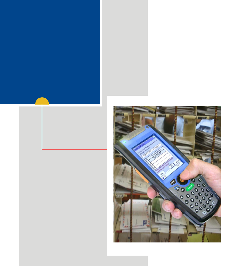
Introduction
This manual covers the basic setup operations and use of the Intelligent
Mail Device (IMD) handheld computer.
The IMD may use a variety of Motorola docking cradles for network com-
munication and power charging. Note that this manual briefly describes
the basic features of each cradle. For detailed installation and operation of
each cradle, refer to the specific user manual of each cradle.
What is the IMD Handheld Computer
The IMD is a rugged handheld computer. The IMD is designed for field
applications where fast mail data acquisition and exchange is required.
The IMD serves as a Personal Digital Assistant (PDA) that enables portable
access to mobile applications, such as: mobile messaging, queries and
Computer Aided Dispatch. It contains a built-in imager for barcode (1D and
2D labels) and signature capturing.
Wireless communication is through 802.11b Local Area Network (LAN,
WiFi) and Bluetooth® connection to peripheral equipment.
The IMD display is a QVGA 3.5 inch transflective TFT. Equipped with a
back-light, the display is designed to enable clear visibility under all light
conditions.
A touch-screen enables easy access to on-screen menu navigation and
signature capturing, using stylus or navigation keys. The screen is
designed to withstand high impact.
The IMD is equipped with an ABC alpha-numeric keypad. The keypad back-
light enables to operate the IMD in low-light conditions.
The operating system is WinCE.net®-based, running Windows® CE-based
applications.

4
The IMD is powered by a 900 mAh 7.2V Lithium-Ion battery pack (1800
mAh battery is also available). The battery is fully recharged within four
hours, using the IMD cradles or battery charger.
When battery is replaced, a built-in power source, independent of the bat-
tery pack, maintains data in the IMD memory for at least 5 minutes.
Unpacking
The IMD package includes the following items:
•One IMD
• One 900 mAh 7.2V (or 1800 mAh 7.2V) Lithium-Ion battery pack
•One Stylus
• Hand-strap
Carefully unpack each item from the shipping carton. Check all items for
shipping damage, and check that you have received all items ordered.
Note: Retain the original carton packaging in the event that the IMD
should need to be returned for service.
The IMD is shipped with a plastic film, protecting the screen. Before
usage, remove the film and use a soft cloth to buff the screen. A clean
screen ensures smooth gliding of the Stylus over the surface.
5
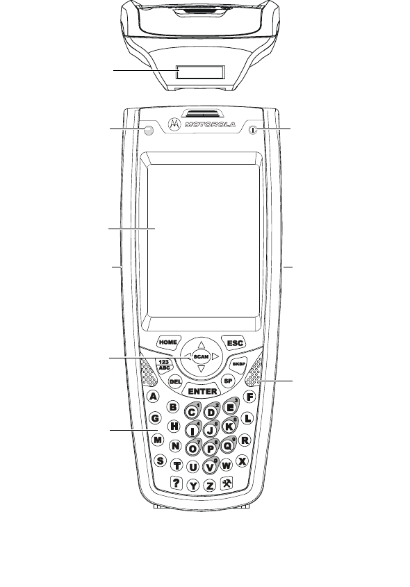
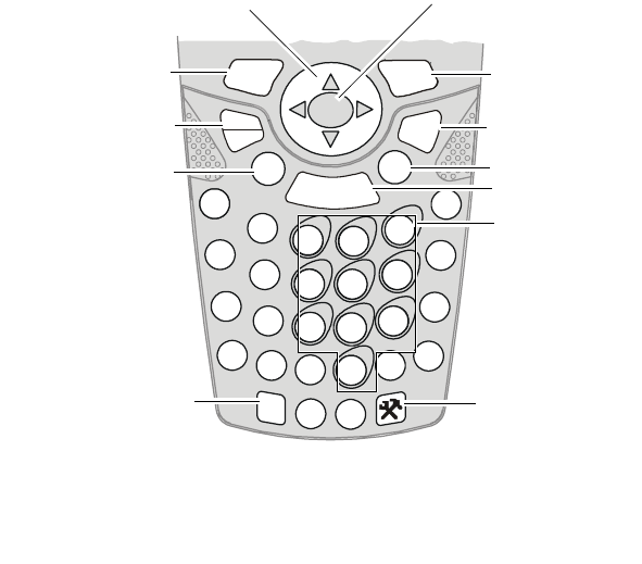
IMD Features
Front Panel and Top Side Features
Main Menu
Application
LED
(refer to the soft-
ware application
guide)
Power
Button/Status LED
(Power, Battery and
Charging Status)
(see page 10) &
(see page 11)
Keypad
(see page 12)
Figure 1. IMD - Front and Top Views
Imager Window
Right Hand
Scan Button
Left Hand
Scan Button
Touch Screen
Speaker
Main
Scan Button
6
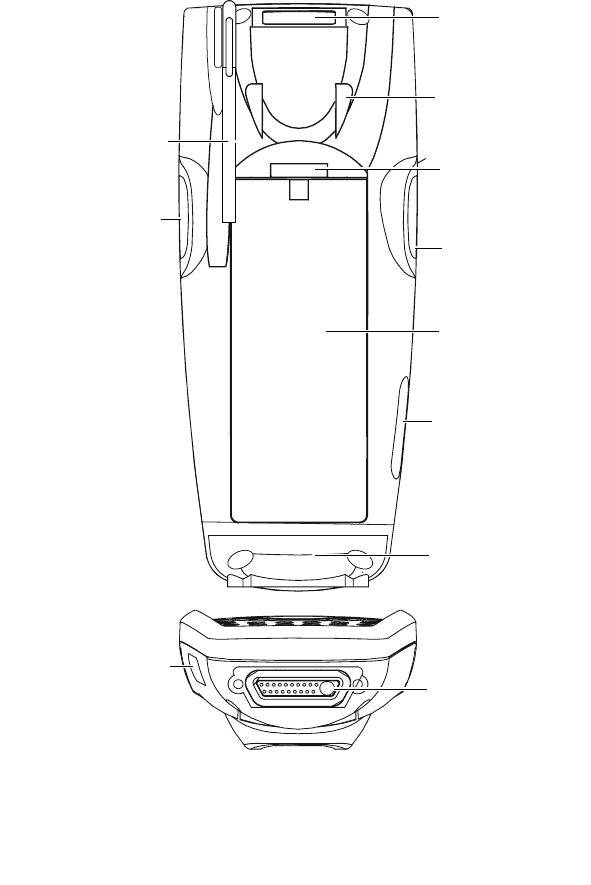
Rear and Bottom Side Features
Figure 2. IMD - Back and Bottom Views
External Connector
Access Door to
the Mini SD
Memory (see
page 19)
Hand-strap
Anchor
Stylus Compartment
Imager Window
Access Door to the
Mini SD Memory
(see page 19)
Battery Release
Button
(see page 7)
Hand-strap
Anchor
Right Hand
Scan Button Right Hand
Scan Button
Battery Pack
7
Charging the Battery
The IMD battery is charged inside the IMD. The battery is shipped from the
factory uncharged and not installed. Install and charge the battery before
using the IMD for the first time.
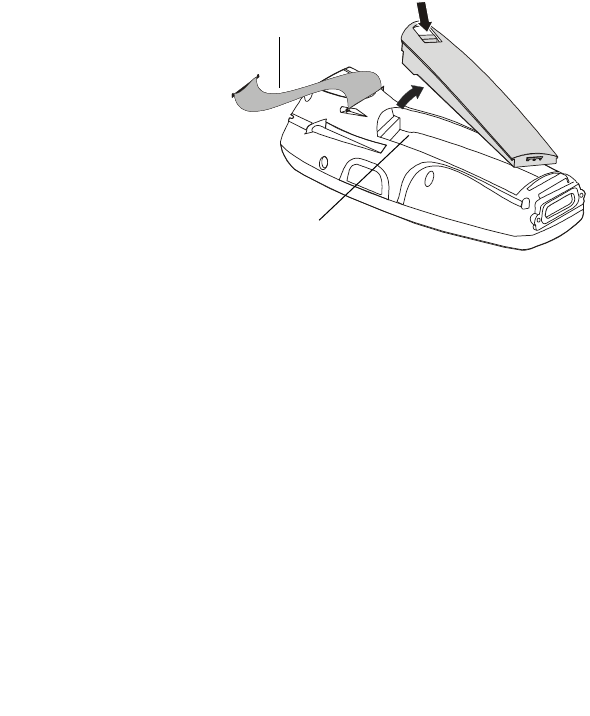
Battery Installation and Removal
Important Note:
The IMD allows you to
replace batteries without
losing information stored in
its memory. To avoid losing
information stored in the
memory, a charged battery
must be installed within
five minutes after removing
the empty battery.
To install the
battery:
1. Disconnect the IMD
hand-strap (see Figure 3).
2. Insert the battery, bottom end first, into the battery compartment.
3. Carefully, press the battery top downward until it clicks and locks in
place - at this stage, the IMD is ready for charging.
To remove the battery:
Press the release button on the battery (see Figure 3) and pull away the
battery from the IMD.
Important: You may remove the battery without turning off the IMD.
Once the battery is removed, data will be maintained in the IMD memory
for no more than 5 minutes. Re-install the battery.
Figure 3. Battery Installation and Removal
Hand-strap
Release Button
Battery
Compartment

8
First Time Battery Charge
Charge the battery before using the IMD for the first time until the Power
Button/Status LED of the IMD shows steady green. While charging, the
Power Button/Status LED shows green and blinks quickly.
The IMD Cradle charges the battery most effectively when it is at room
temperature [approx. 68°F (20°C)]. Battery charging temperature range is
32°F to 95°F (0°C to 35°C).
Routine Battery Charge
A battery is charged to 90% of its full capacity after approximately three
and a half hours. The battery is fully charged after four hours. During the
charge, the Power Button/Status LED shows steady red and turns green
when charging is completed.
Important: The battery will not charge if the IMD is not properly docked
inside the IMD Cradle.
Battery Maintenance
The performance of the rechargeable battery delivered with the IMD
depends on the way the battery is treated. Therefore, to comply with
Motorola Warranty for batteries and to assure high performance and a
long life for the rechargeable battery, please read and follow the battery
maintenance sections below.
Battery Storage
Do not store the battery where the temperatures exceed 140°F (60°C) or
fall below -4°F (-20°C).
Batteries that have never been charged before may be stored for up to 3
months in well-ventilated, cool and dry areas without significant loss in
lifespan.
Batteries which have already been charged and then stored for more than
2 months should be recharged before use.

9
Extending Battery Life
A battery is an expendable part and may need replacing during the life of
the IMD. To ensure maximum service life of the IMD, always replace the
battery with a genuine Motorola replacement.
The IMD Cradle will charge the battery most effectively when it is at room
temperature [approx. 68°F (20° C)]. Battery charging temperature range is
32°F to 95°F (0°C to 35°C).

10
Using the IMD
Turning On the IMD
Press the Power Button/Status LED (see Figure 1) to turn on the IMD.
Turning Off the IMD
When the IMD is On, hold the Power Button/Status LED pressed for at
least four seconds - the IMD will remember the last used screen and will
go into deep sleep mode - no information will be lost. Once turned on
again, the IMD will show the last screen that was in use.
Suspend Mode
When the IMD is turned on, momentarily press on the Power Button/Sta-
tus LED to enter Suspend mode (see Figure 1). During Suspend mode the
display turns off and the Power Button/Status LED slowly blinks green. To
resume operation, press momentarily on the Power Button/Status LED
again.
In Suspend mode, battery power is saved by an automatic turn off of the
display and the computer sections of the IMD. During Suspend mode, the
Bluetooth radio continues to operate. When the IMD resumes operation, it
returns to the screen shown prior to Suspend mode.
The IMD may also move to Suspend automatically if not in use for some
time.
Use Suspend mode as often as possible to conserve battery power.

11
Visual indications of Power Button/Status LED
The Power Button/Status LED has a 3 color LED (red/yellow/green) to indi-
cate the power, battery and charging status (see Figure 1).
The LED indications differ when the IMD is used out of the cradle and
inside the cradle.
LED indications when IMD is out of the cradle
LED slowly blinks green - IMD in Suspend mode.
LED shows steady red for 5 seconds - IMD is booting-up following bat-
tery replacement. Important: to avoid system failure, do not remove the
battery during boot-up.
LED Indications When IMD is in the cradle
LED shows steady red - battery is charging.
LED shows steady green - battery is fully charged.
LED blinks yellow - battery temperature or voltage is out of range - bat-
tery charging is stopped. Charging will resume when temperature or volt-
age is back within range.
LED blinks red - charging error/bad battery. Re-install the IMD in the cra-
dle or replace battery.
12
Using the Keypad
The IMD keypad enables the user to input both alphabetic and numeric
data to the software application. However, since the keypad can only con-
tain a limited number of keys, some special keys are assigned to perform
special tasks that are usually found on full-size computer keyboards. These
are produced using a combination of the existing keys on the IMD keypad.
Two sets of keys exist on the IMD:
1. Keys active when in Alphabetic mode, which are those seen on the
overlay of the IMD keypad.
2. Keys active when in Numeric mode which are those seen in the num-
bered oval shapes on the IMD keypad.
Press the “Alpha-numeric” key to toggle between the Alphabetic and
Numeric modes
S
M
G
B
?
YZ
X
R
L
F
CDE
HI
A
JK
NOPQ
TUV
W
DEL SP
SCAN
12
3
45
6
9
87
0
ENTER
BKSP
ABC
123
ESC
HOME
Figure 4. IMD - Key Function
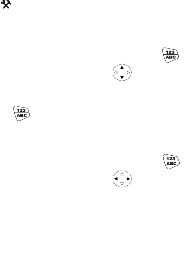
Navigation Keys
Enter Key
Space Key
Back Space Key
Escape Key
Configuration Key
Delete Key
Alpha-numeric
Shift Key
Home Key
Help Key
Main Scan Button
Numeric Keys

13
<SCAN>: The Imager trigger button is used for scanning images (refer to
“Capturing Images” on page 16).
<ENTER>: The <ENTER> key is used to continue to the next screen (i.e.
continue processing).
Navigation Keys: The <Up Arrow> and <Down Arrow> keys are used to
scroll up and down on menu, form and data list screens. The <Right
Arrow> and <Left Arrow> are used for horizontal navigation between
action buttons and areas such as: date controls, time controls, data table
controls, and for closing list boxes.
<Home>: The <Home> key serves as an Esc key The <Home> key is used
to cancel the current action and return to the previous screen or possibly
display a confirmation screen. Any data entered on the screen via scanned
entry, keyed entry, or menu selection is ignored. the key is also used to
closes list boxes, combo boxes and pop up windows without changing the
data.
<DEL>: The <DEL> key deletes the character at the current cursor position
in the field. The <DEL> key is only active on data entry screens.
<SP>: Enables to enters blank space within a text field. The <SP> key is
active only on those text entry screens which contain fields that allow
spaces to be entered.
<BKSP>: The <BKSP> key moves the cursor to the previous character in
the field, and erases the character in its new position. Any remaining char-
acters to the right of the cursor are shifted to the left by one. If there are
no more characters to erase, the Scanner beeps. The <BKSP> key is only
active on data entry screens.
<123/ABC>: The Alpha-numeric key shift between alphabetic and numeric
keypad modes to shift between digit entry and letter entry. For example,
the '8' key in non- <123/ABC> mode becomes “B”.
Press <123/ABC> + any alphabet key for uppercase letter (Default is lower-
case letters).
14
? Help: This key is pressed to popup help window when Help application
is available. To know more about the key, consult the software application
guide of the IMD.
Configuration: The configuration key is pressed to popup mainte-
nance application window, when maintenance application is avail-
able. To know more about the key, consult the software application guide
of the IMD.
Screen Back-Light Adjustment
The screen Back-light can be adjusted by simultaneously holding
pressed and pressing the up or down arrows to increase or
decrease the screen Back-light.
Turning on & off the Screen Back-light
Hold press for 2 seconds - the screen Back-light will turn on. To
turn off - hold pressed for another 2 seconds.
When not in use, Back-light turns off automatically after 10 seconds.
Keypad Back-Light Adjustment
The keypad back-light can be adjusted by simultaneously holding
pressed and pressing the right or left arrows to increase or
decrease the screen back-light.

15
Turning on & off the Keypad Back-light
Hold press for 4 seconds - the screen Back-light will turn on. To
turn off - hold pressed for another 2 seconds.
When not in use, Back-light turns off automatically after 10 seconds.
16
Capturing Images
The IMD houses a digital camera (Imager) that captures pictures and
decodes the most commonly used 1D and 2D bar codes. The IMD supports
360° omni-directional operation for easy use in daily work. The Imager
captures digital images, such as signatures, text or pictures of any object
or form. The images are stored in the IMD memory.
To capture an Image:
1. Aim and hold the IMD
at approximately 2 to
12 inches (5 to 30 cm)
away from the target.
2. Press the Imager Scan
button and aim the
green aiming pattern
towards the target to
adjust your position.
Note that when the
IMD is held closer to
the barcode the green
aimer appears smaller
when held farther from
the barcode it appears
larger. Barcode sym-
bols with dense symbol
elements should be
read closer to the IMD
and large barcode with
larger symbol ele-
ments should be read
at a larger distance (Depth-of-Field) from the IMD.
20°Vertical & 40° Horizontal Capture Angle
Hold 2 to 12 inches (5 to 30 cm) from target
Scan Button
Figure 5. Capturing Images with the IMD Imager
CLASS 1 LED PRODUCT
IEC 60825-1 ED 1.2:2001
Scan Buttons
Imager Window
20°
40°

17
To capture a barcode, aim the green aimer bar in any angle across the bar-
code, as shown in Figure 6
Note: When adjusting your position, you may move back and forth from
the target to capture the entire object - a successful scan may be followed
by sound indication.
Figure 6. IMD Imager - Barcode Capture Position
2D Barcode Symbol
1D Barcode Symbol
18
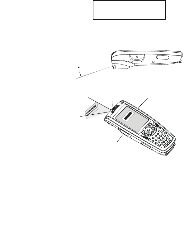
Resetting the IMD
You may need to reset the IMD; for example, you may reset due to commu-
nication cut-off, or if the operating system or the application stops
responding.
If the IMD stops responding, perform the following steps:
Step 1: Warm Reset
Important Note: When the IMD
performs Warm Reset, all
recorded information remains
stored in memory.
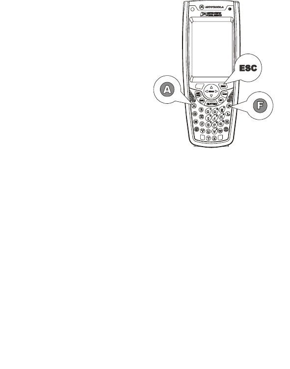
Simultaneously, press keys
ESC + A + F (see Figure 7) for
at least 5 seconds - the Motorola
logo will show on the screen for
about 30 seconds and then WinCE
desktop will appear - the IMD
functions again.
If the IMD still does not respond,
perform “Step 2: Cold Reset”:
Figure 7. Warm Reset - Key Combination
19
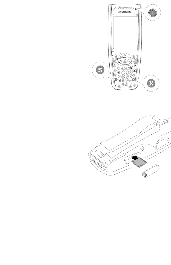
Step 2: Cold Reset
Cold Reset restarts the IMD by
erasing all stored records and
entries.
Do Not perform Cold Reset unless
Warm Reset fails to solve the
problem.
Press the Power Button/Status
LED + S + X keys simultaneously
for at least 5 seconds (see Figure
11); the IMD will restart its oper-
ating system.
Mini SD Memory Card
Installing a Mini SD Card
1. Turn off the IMD.
2. Remove the screw to open the
cover of the Mini SD (Secure
Digital) card slot (see Figure 2).
3. Insert the Mini SD card as
shown in Figure 9.
Important: Turn the IMD power off
before removing or installing the
Mini SD card.
Mini SD Card Handling Precautions
• Use only the supplied Mini SD card.
• Do not bend or apply force on the Mini SD card.
• Do not store the Mini SD card in locations subjected to high humidity
or temperatures.
Figure 8. Cold Reset - Key Combination
Figure 9. Mini SD Card Installation

20
Maintaining the IMD
In order to maintain the IMD in good working order:
• Do not scratch the screen. Use only Motorola supplied stylus pen.
• Never use a pen or pencil or any sharp object on the screen.
• Protect the IMD from temperature extremes. Do not leave the IMD on
the dashboard of a car on a hot day, and keep the IMD away from hot
places.
• Do not store or use the IMD in any location that is extremely dusty,
damp or wet.
• If the battery contacts, screen or surface of the IMD become dirty, use
a soft lint free cloth moistened with diluted Isopropyl Alcohol (IPA)
solution to remove dirt. The Isopropyl Alcohol (IPA) can be diluted with
water up to 20%.
Accessories
The following Motorola approved accessories are for use with the IMD.
Table 1: Accessories
Motorola Approved Accessory Part Number
IMD Communication/Charger Cradle 8 Bays F3147
IMD Communication/Charger Cradle 4 Bays F3141
IMD Communication/Charger Cradle 2 Bays F3149
IMD Communication/Charger Single Bay F3146
IMD Vehicle Cradle F3128
IMD 8 Slot Multi-Battery Charger F3142
IMD Battery 1800 mAh FNN7815

21
It is the responsibility of the user to use only the approved accessories
supplied for this product, as detailed in Table 1 . Motorola is not responsi-
ble for the use of accessories not approved for this product.
For more information on the availability of these accessories, please call
your company supplier.
IMD Battery 900 mAh FNN7818
IMD Stylus 0104611P06
IMD Holster FTN646
IMD Hand-strap FHN6621
Table 1: Accessories
Motorola Approved Accessory Part Number

22
Troubleshooting
Table 2: Troubleshooting the IMD
Problem Cause Solution
IMD does not
turn On
Battery is not
installed properly or
not charged
Ensure proper battery installa-
tion in IMD.
Charge or replace the battery
IMD in Suspend mode Press the Power Button/Status
LED
Battery does not
charge in IMD
Cradle
IMD is not locked in
IMD Cradle
Re-install IMD in IMD Cradle.
Place the IMD properly in IMD
Cradle. (Verify that the IMD Cra-
dle LED is On and charge for
three hours)
IMD Cradle contacts
are not clean
Clean contacts and remove dust
and objects from within the IMD
Cradle
Battery temperature
is out of range
Ensure that the battery tempera-
ture is within range. (refer to
“Charging the Battery” on
page 7)
Bad battery Replace battery
IMD does not
detect scan
input
Aiming pattern not
directed to the bar-
code symbol
Scan again and make sure that
the green light is aimed across
the barcode
Check for readable barcode (not
covered, or abstracted)
Unreadable barcode Be sure the barcode symbol is
not covered, damaged or
obstructed

23
IMD does not
respond
Problem in IMD oper-
ating system or com-
munication network
Ensure proper battery installa-
tion in IMD.
Charge or replace the battery
Execute Warm Reset “Resetting
the IMD” on page 18. The IMD
should function again
If IMD still does not respond,
perform Cold Rest (see “Reset-
ting the IMD” on page 18). The
operating system will reboot in
30 seconds
Incomplete or no
data transmis-
sion between
IMD and IMD
Cradle
Communication soft-
ware was incorrectly
installed or config-
ured
Refer to the IMD Cradle user
manual or see your system
administrator
Table 2: Troubleshooting the IMD
Problem Cause Solution

24
Safety Instructions
IMD On-board Aircraft
Always remove the battery from the IMD when shipped via air. Any use of
the IMD must be in accordance with applicable regulations per airline
crew instructions.
Battery Disposal
Batteries must be recycled or disposed of properly in accordance with local
requirements. Recycling facilities may not exist in all areas. Please contact
your local environmental agency for more information regarding proper
disposal.
To Prevent Injury or Burns
• USE ONLY SPECIFIED BATTERIES AND CHARGERS - RISK OF EXPLO-
SION IF BATTERY IS REPLACED BY AN INCORRECT TYPE!
• DO NOT DISPOSE OF ANY BATTERIES IN FIRE, AS THEY MAY
EXPLODE!
• DO NOT PUNCTURE OR ALLOW METAL TO CONTACT THE BATTERY
TERMINALS
• DO NOT DISPOSE OF IN WATER
• DO NOT DISASSEMBLE
• DO NOT STORE ABOVE 140°F (60°C) OR BELOW -4°F (-20°C)
Battery Warnings and Disposal

25
SPECIFICATIONS
PHYSICAL SPECIFICATIONS
Weight 16.1 Ounces (461 g), including the standard
capacity battery (900 mAh)
Dimensions Width x Length x Depth: 3” x 7.7” x 1.93”
(77.8 x 197.6 x 49 mm)
ELECTRICAL SPECIFICATIONS
Power Supply From external connector (Cradle connec-
tion): 10 to 15VDC, maximum current 1.5A
From Li-Ion battery pack: 5.4 to 8.4VDC,
maximum current 1.5A,
Processor Type Intel PXA270
Memory Flash: 64 MB (128 option), SDRAM: 64 MB
Display 3.5” color, transflective, 64K color LCD with
up to 55 cd/m2 (NIT) luminance. Resolution:
240 x 320 pixels (1/4 VGA)
Touch Screen Resistive analog 4-wire touch panel. Ten bit
resolution digitizer with 1024 X 1024
points.

26
Keyboard 36 keys:
- 26 alpha (A-Z) keys
- 4 scroll keys
- 2 soft (programmable) function keys
- 3 scan keys, one front mounted and one
on each side of the terminal
- 7 function keys
- 1 power on/off key with 3 color LED
Status Indicator Two Tricolor LEDs:
1. Software controlled
2. Integrated inside Power button
Audio Speaker: Mono 0.5 W speaker for produc-
ing audible alerts. adjustable volume. The
sound pressure level at 10 cm is at least 75
dBA at 2,200 Hz.
Personal Area Network
(PAN)
Bluetooth V1.2 port communication to wire-
less accessories

27
Barcode Imager IT4100SR:
Image Engine with AdaptusTM imaging tech-
nology that implements area imaging for
both 1D and 2D reading as well as capture
of signatures.
- Lighting conditions ranging from complete
darkness to 100,000 lux [depth of field
specification may be reduced under condi-
tions of less than 535 lux (50fc)].
- Viewing angle around the normal at the
nominal operating distance, pitch and
skew: 40º
Rotation around the optical axis: 360º The
scanner may not operate under conditions
of spectral reflection +/- 5º
Supported symbologies:
· UCC/EAN 128
· USS Code 128
· Postnet and Planet Code
· 4-state
· USS Code Interleaved 2 of 5
· Code 93
· USS 39
· PDF 417
· DataMatrix
· UPC
Main Battery Lithium-Ion, 7.2V, 900 mAh (1740 mAh
optional). Fully recharged within 4 hours in
cradle.
Backup source A secondary (backup) power source com-
prising two "super-caps", independent of
the primary battery. The capacitors provides
backup for at least 5 minutes while the
main battery is replaced.

28
Software
Operating System WinCE.net®-based operating system (run-
ning Windows® CE-based applications)
Communication
Personal Area Network (PAN): Bluetooth
1.2 RF communication to wireless equip-
ment
Wi-Fi Wireless Local Area Network (WLAN)
with integrated antenna for software
debugging:
Network Standard IEEE 802.11b
Frequency Band 2.400-2.474 GHz (2.4 GHz
ISM Band)
Full RS-232 serial port and USB 1.1 client
port for wired connections to Communica-
tion network cradle and peripheral devices
such as printers

29
ENVIRONOMENTAL SPECIFICATIONS
Operational
Temperature
(without degradation)
32º F (0º C) to 122º F (50º C).
See below * for operation between
-18º F (-28º C) to 32× F (0º C)
Storage Temperature -22º F (-30º C) to 158º F (70º C), 24 hours
soak, without battery
Humidity 8 hours at 122º F (50º C) 5-95% RH with
power off during soak time. The unit will
then be turned ON and fully tested while in
the temp & humidity conditions. Battery
charging is automatically stopped above 95º
F (35º C).
Dripping Rain MIL-STD-810F, Method 506.4 Proc II –
water tightness
Altitude According to IEC 68-2-13/MIL-STD-810F,
Method 500.4
Operating 15,000 ft (4.5 km)
Blowing Dust MIL-STD-810F, Method 510.4 Proc I – blow-
ing dust
Shock (Functional) Total 18 impacts, hard mounted.
Operating: 15g, 11ms, half sine wave
Non-operating: 30g, 11ms, half sine wave
Vibration Duration 1 hour/axis, hard mounted.
Operating: 10-55 Hz, 0.075 mm, 55-500 Hz,
1.0g
Non-operating: 10-55 Hz, 0.15 mm, 55-500
Hz, 2.0g
Drop MIL-STD-810F, Method 516.5, 26 drops
from 4 ft. high.
Test surface: concrete
Enclosure Class
(Rain & Dust)
IP X4 (Rain)
IP 5X (Dust) Category 2 (no vacuum pump)

30
ESD Per EN61000-4-2
8 KV contact, 15 KV air.
No permanent failure or loss of data, reset
is allowed.
Radiation & Susceptibility
Approvals
FCC 47CFR part 15, subpart A and C.
EN 55024:1998, IEC801-3, IEC801-4,
EN50082-1 & -2
Safety UL marking based on UL 60950-1
* Operational Temperature with
degradation
(based on Motorola testing)
LCD From -18º F (-28º C) to 32º
F (0º C):
Response time up to ½
sec
Min. Contrast:
– Reflective 2:1
–Transmissive 20:1
Backlight – No degrada-
tion
Imager From -18º F (-28º C) to 32º
F (0º C):
Near Field DOF – 40%
degraded
Far Field DOF -20%
degraded
Touch Screen
Activation
Force
From -18× F (-28º C) to 32º
F (0º C): 0.53 to 5.64 oz.
(15 to 160 gm)

31
Battery Degra-
dation
( % of capacity
w/temp, 100%
at 77× F (25º C),
0.2C discharge
rate.)
At 14º F (-10º C): 85%
At -4º F (-20º C): 50%
At -18º F (-28º C): 35%

Index - 1
Index
A
Accessories 20
Aircraft 24
B
Battery Charge 8
Battery charging temperature 8
Battery Maintenance 8
Battery Storage 8
Battery Warnings 24
C
Charging 7
Cold Rese 19
cool and dry areas 8
D
Disposal 24
E
Extending Battery Life 9
I
Injury 24
Install Battery 7
Isopropyl Alcohol 20
L
Laser Warning 16
LED shows green 8
LED shows red 11
M
Maintaining 20
N
Navigation Key Panel 6
P
PowerPad Parts 5
R
Remove Battery 7
Resetting 18
room temperature 8
S
Safety Instructions 24
Scan Angle 16
Scanning 16
Speaker 5
storage temperatures 8
store 20
Suspend Mode 10
T
Touch Sensitive Screen 5
Troubleshooting 22
Turning Off 10
Turning On 10
U
Universal Office Docking 8
Unpacking 4
W
Warm Reset 18

2 - Index

HOW TO REACH US:
Government & Enterprise
Mobility Solutions
1301 E. Algonquin Road,
Schaumburg, IL 60196
Tel: 1-888-567-7347 (inside the US)
Tel: 1-847-576-5000 (outside the US)
Visit our Web site at
www.motorola.com
MOTOROLA and the Stylized M Logo are regis-
tered in the U.S. Patent and Trademark Office.
All other product or service names are the prop-
erty of their respective owners.
© Motorola, Inc. 2005.