Motorola Solutions 89FT7608 ML900 Notebook PC w/ CDMA Modem User Manual ML900 0
Motorola Solutions, Inc. ML900 Notebook PC w/ CDMA Modem ML900 0
UserManual.wiki
>
Motorola Solutions
>
89FT7608 User Manual
>
Users Manual 2
Contents
1.
Users Manual 1
2.
Users Manual 2
3.
Users Manual 3
Users Manual 2
Navigation menu
Upload a User Manual
Namespaces
Wiki Guide
HTML
PDF
Info
Views
User Manual
Discussion / Help
Navigation

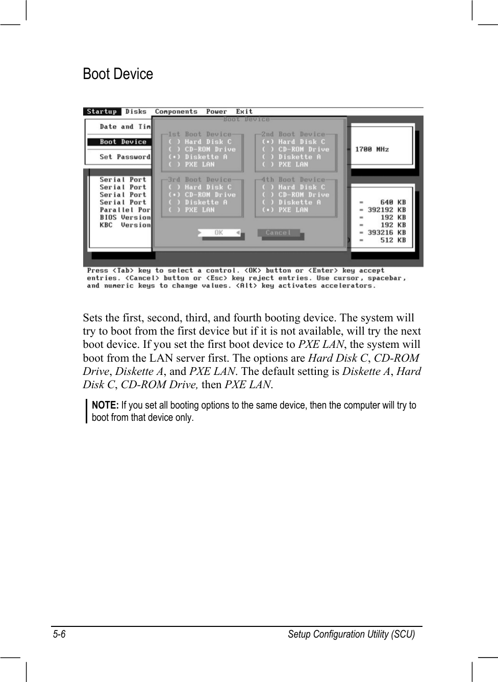
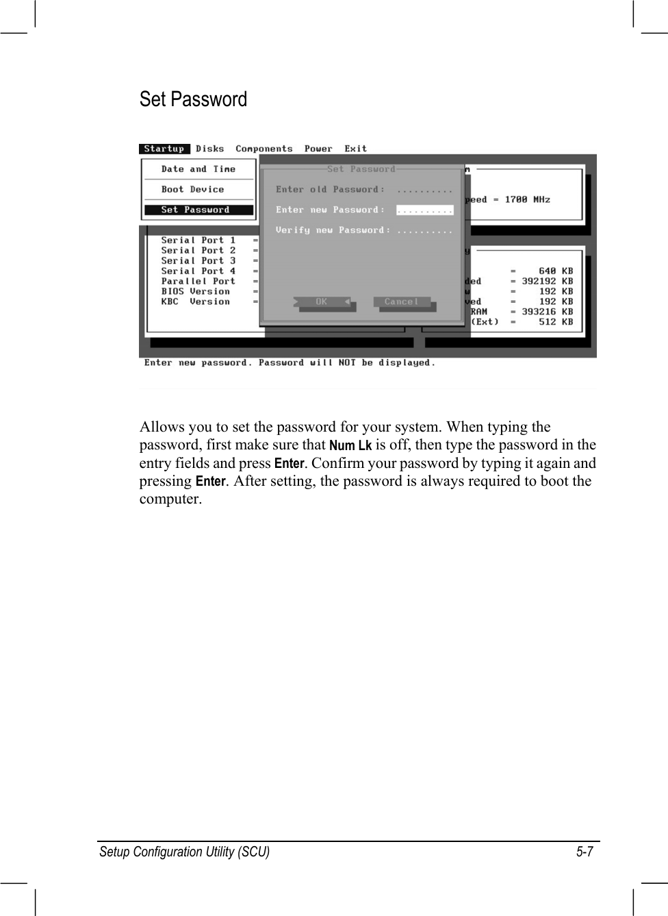
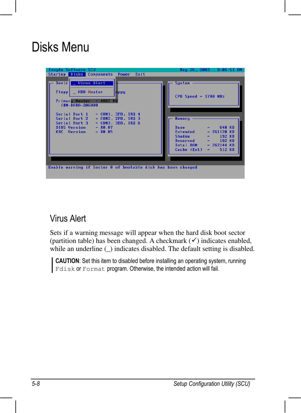
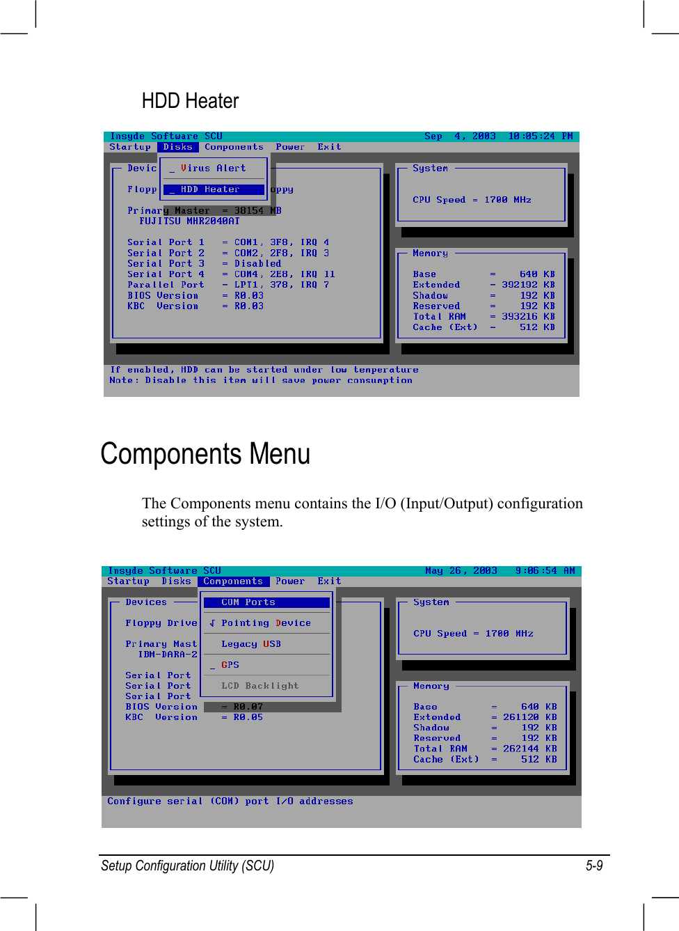
![Setup Configuration Utility (SCU) 5-13The Enable USB Port sub-item enables or disables the USB port inDOS mode. The options are enable and disable. A [X] mark indicatesenable, while blank [ ] indicates disable. Default setting is enable.The USB Keyboard sub-item enables or disables the USBkeyboard in DOS mode. The options are Enable and Disable.Default setting is Enable. This item is not valid for setting if theEnable USB Port sub-item is disabled.The USB Floppy sub-item enables or disables the USB floppy drivein DOS mode. The options are Enable and Disable. Default setting isEnable. This item is not valid for setting if the Enable USB Portsub-item is disabled.GPS](https://usermanual.wiki/Motorola-Solutions/89FT7608.Users-Manual-2/User-Guide-411316-Page-24.png)