Motorola Solutions 89FT7613 2.4 GHz Wireless LAN Module User Manual ML900 0
Motorola Solutions, Inc. 2.4 GHz Wireless LAN Module ML900 0
Contents
- 1. Users Manual 1
- 2. Users Manual 2
- 3. Users Manual 3
Users Manual 2

Expanding Your Computer 4-5
Connecting an IR Device
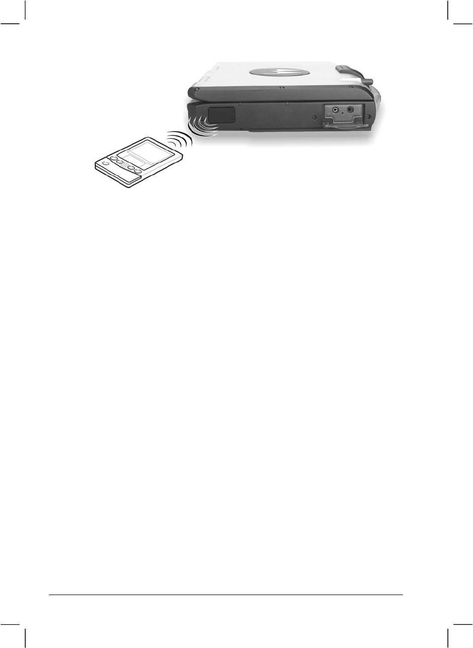
Your computer has an IR (infrared) port for connecting an infrared-
equipped device wirelessly such as another computer, printer, or PDA
(Personal Digital Assistant).
Follow this procedure to connect an IR device:
1. Under Windows, make sure that the IrDA Fast Infrared Port is set to
HP HSDL-2300/3600. (See “How to Use the Driver CD” in Chapter
6 for information.)
2. Make sure that the “COM Ports” and its “Mode Setting For COM2”
items are set properly in the SCU program. (See “Components
Menu” in Chapter 5 for information.)
3. When using the IR port:
Place the transmitting device where its IR port faces the IR port of
your computer within the effective range − within ±20-degrees
vertical angle and within ±20-degrees horizontal angle at no greater
than 0.8~1.0 meter distance.
Place the receiving device where the IR port of your computer faces
its IR port within the effective range − within ±15-degrees vertical
angle and within ±15-degrees horizontal angle at no greater than
0.8~1.0 meter distance.
4. To take advantage of the IR communications, you need a third party
software.
NOTES: During infrared communication, take note of the following:
l Do not move the computer and IR device.
l Do not enter Standby mode.
l Do not use a cell phone or another IR device near the computer.
l Avoid strong light such as sunlight or fluorescent light.
l Disable the screen saver.
4-6 Expanding Your Computer

Expanding Your Computer 4-7
Connecting a Bluetooth-compliant Device
(option)
NOTE: To take advantage of the Bluetooth feature, the Bluetooth driver supplied with
your computer must be installed (see chapter 6 for details).
Your computer has a Bluetooth port for connecting a Bluetooth-
compliant device wirelessly. Bluetooth is a short-range wireless
communications technology. Devices with Bluetooth capabilities can
exchange information over a distance of about 10 meters (30 feet)
without requiring a physical connection.
Unlike infrared, you do not need to line up the devices to beam
information with Bluetooth. The devices only need to be within a range of
about 10 meters. You can even beam information to a device in a
different room, as long as it is within range.
You may use Bluetooth in the following ways:
• Beam Information – such as files, appointments, tasks, and contact
cards, between devices that have Bluetooth capabilities. For example,
if you and a co-worker each have a device with Bluetooth, you can
beam items between your devices, such as files, contact cards,
appointments, tasks, and so forth.
• Create a dial-up modem connection – between your device and a
Bluetooth phone. You can then use the Bluetooth phone as a modem.
Bluetooth operates in three different modes:
• On – the Bluetooth radio is turned on and you can use Bluetooth
features.
• Off – the Bluetooth radio is turned off. In this mode, you can neither
send nor receive information by using Bluetooth. You might want to
turn the radio off at times in order to conserve battery power, or in
situations where radio use is prohibited, such as on airplanes and in
hospitals.

4-8 Expanding Your Computer
• Discoverable – the Bluetooth radio is turned on, and all of the other
Bluetooth devices within range (about 10 meters) can detect your
device and attempt to beam information to it, establish a bond, or use a
Bluetooth service. In this mode, other devices can detect your device
whether or not a bond has been created; however, in order to receive a
beam from another device, you must accept it on your device.
About Bonds
A bond is a relationship that you create between your computer and
another Bluetooth device in order to help exchange information in a
secure manner. Creating a bond involves entering the same PIN on the
two devices you want to bond. Once a bond is created, the devices need
only have their Bluetooth radios turned on to exchange information; they
do not need to be in discoverable mode.
You need only create a bond once between two devices. Thereafter, they
recognize the bond and are able to exchange information without your
entering a PIN again.
Expanding Your Computer 4-9
Connecting an IEEE 1394 Device
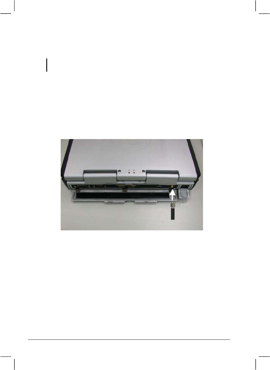
Your computer has an IEEE 1394 port on the right side of the computer
for connecting 1394 devices.
IEEE 1394 is the next-generation serial bus standard, featuring high-
speed data transfer, multi-channel communication link, and “Hot Plug”
connectivity. It allows connection of up to 63 devices. The applications
include not only computer peripheral devices such as scanner, printer and
high-quality CCD, but also consumer electronic equipment such as
DVCAM and VCR.
To connect an 1394 device, simply plug the device cable to the IEEE
1394 port of the system.
4-10 Expanding Your Computer
Connecting a Video Capture Device
NOTE: To take advantage of the AV input port, the Video Capture driver supplied with
your computer must be installed (see chapter 6 for details).
Your computer has an AV input port on the rear of the computer for
connecting a video capture device such as high-quality CCD, as well as
consumer electronic equipment such as DVCAM and VCR.
To connect a video capturing device, simply plug the device cable to the
AV input port (conexant 878A PCI; BNC-type) of the system.
System Memory Upgrade
You can upgrade your computer by changing system memory to a
maximum of 1 GB on the two 200-pin PC2100 DDR SO-DIMM slots.
However, to avoid damage during the installation procedure, please ask
your dealer for help.

CHAPTER 5
Setup Configuration Utility (SCU)
SCU is a program for configuring the BIOS (Basic Input/Output System)
settings of the computer.
BIOS is a layer of software, called firmware, that translates instructions
from other layers of software into instructions that the computer hardware
can understand. The BIOS settings are needed by your computer to
identify the types of installed devices and establish special features.
This chapter tells you how to use the SCU program.

Setup Configuration Utility (SCU)5-2
When and How to Use the SCU Program
When to Use
You need to run the SCU program when:
l You see an error message on the screen requesting you to run Setup.
l You want to restore the factory default settings.
l You want to modify some specific settings according to the
hardware.
l You want to modify some specific settings to optimize system
performance.
Starting SCU
NOTES:
l The Setup screens shown in this chapter are for your reference only. The actual
items or settings on your computer may differ.
l The Setup program may have been updated after the publication of this manual.
l The settings you select in your operating system might override similar settings in
Setup.
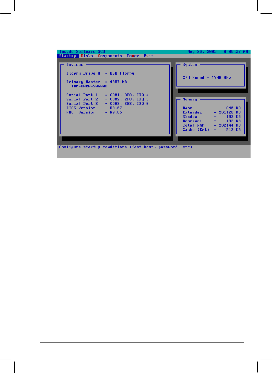
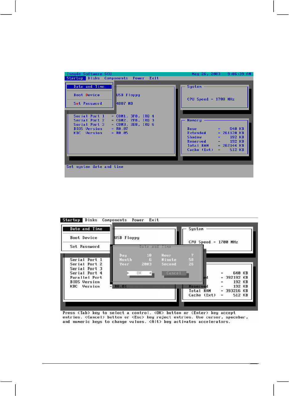
To run SCU, press F2 when the prompt appears in the lower left corner of
the screen during system startup. The prompt shows up on the screen for
only a few seconds. You must press F2 quickly. The SCU menu appears
as shown next.
Setup Configuration Utility (SCU) 5-3
The menu can be divided into four areas:
l On the top line is the menu bar containing the titles of the available
menus. Each menu title brings a specific menu.
l The center left column of the menu contains information regarding
the current settings of the system. If you open a pull-down menu and
select an item that provides multiple options, the left column will
display a submenu where you can make further selections.
l The right column of the menu contains details of the CPU and system
memory.
l The bottom lines of the menu provide keyboard instructions for
moving around and making selections. When a menu item is
highlighted, more detailed information is given.

Setup Configuration Utility (SCU)5-4
Moving Around and Making Selections
A brief description of keyboard usage is listed next:
Key Function
←, →Selects a menu title.
↑, ↓1) Selects an item or option.
2) Brings up/down the value.
Enter 1) Brings up the sub-menu when available.
2) Opens or closes the options window when an item is selected.
Tab Jumps from one item to another.
Esc 1) Exits the SCU program.
2) Returns to the previous menu if in a sub-menu.
3) Closes the options window if one is open.
NOTE: You are advised to use the touchpad (if enabled) as it is more straightforward
than using the keyboard.
Setup Configuration Utility (SCU) 5-5
Startup Menu
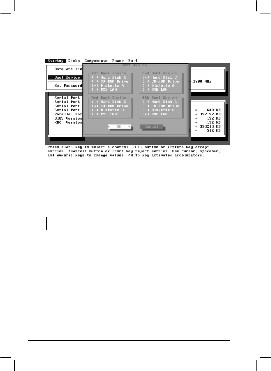
Date and Time
Sets the system time (Hour, Minute, Second) and date (Month, Day,
Year).
Setup Configuration Utility (SCU)
5-6
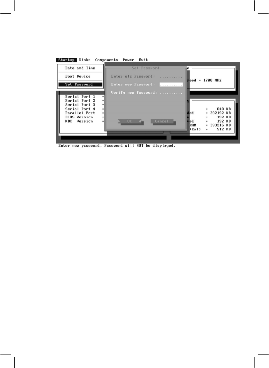
Boot Device
Sets the first, second, third, and fourth booting device. The system will
try to boot from the first device but if it is not available, will try the next
boot device. If you set the first boot device to PXE LAN, the system will
boot from the LAN server first. The options are Hard Disk C, CD-ROM
Drive, Diskette A, and PXE LAN. The default setting is Diskette A, Hard
Disk C, CD-ROM Drive, then PXE LAN.
NOTE: If you set all booting options to the same device, then the computer will try to
boot from that device only.
Setup Configuration Utility (SCU) 5-7
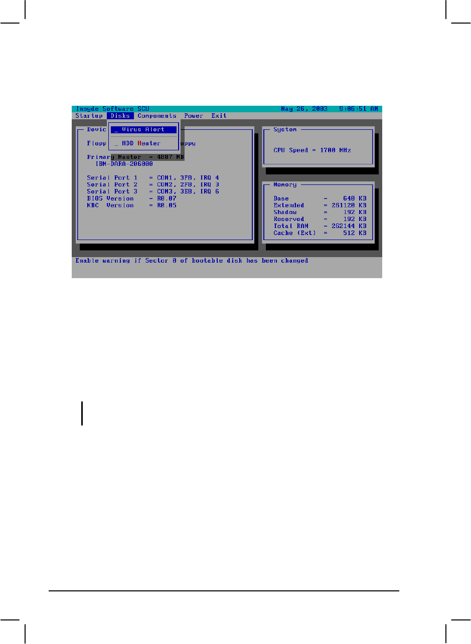
Set Password
Allows you to set the password for your system. When typing the
password, first make sure that Num Lk is off, then type the password in the
entry fields and press Enter. Confirm your password by typing it again and
pressing Enter. After setting, the password is always required to boot the
computer.
Setup Configuration Utility (SCU)5-8
Disks Menu
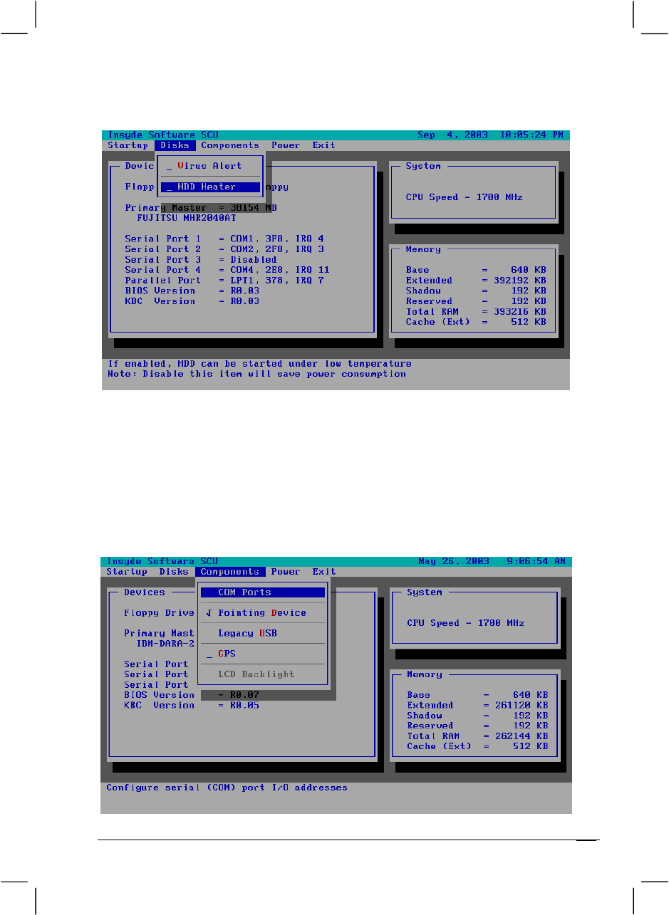
Virus Alert
Sets if a warning message will appear when the hard disk boot sector
(partition table) has been changed. A checkmark (ü) indicates enabled,
while an underline (_) indicates disabled. The default setting is disabled.
CAUTION: Set this item to disabled before installing an operating system, running
Fdisk or Format program. Otherwise, the intended action will fail.
Setup Configuration Utility (SCU) 5-9
HDD Heater
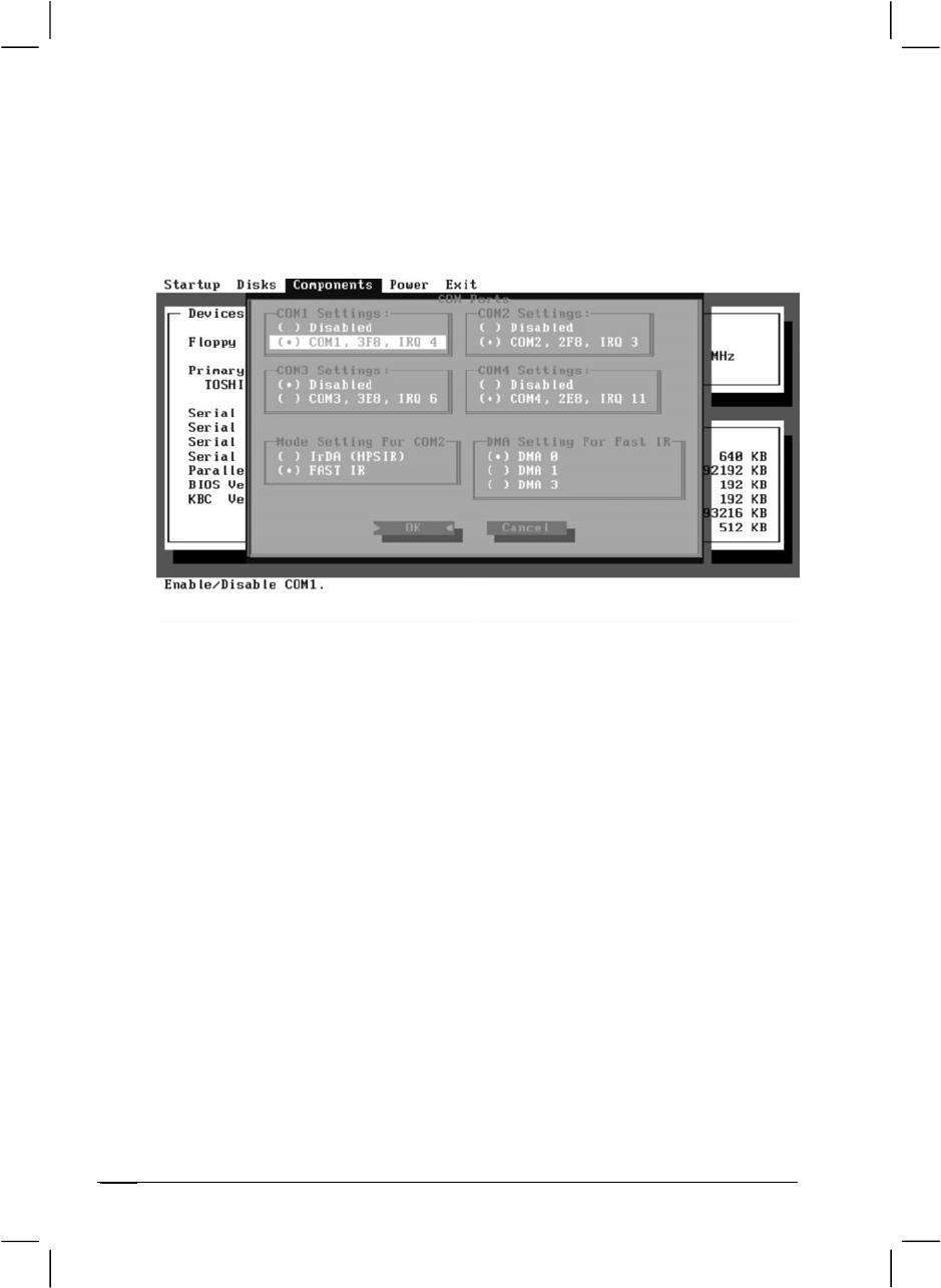
Components Menu
The Components menu contains the I/O (Input/Output) configuration
settings of the system.
Setup Configuration Utility (SCU)
5-10
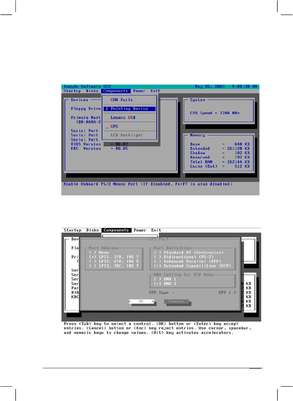
COM Ports
Allows you to configure the COM ports of the computer.
COM1/2/3/4 Settings sets the I/O (Input/Output) address and the
Interrupt ReQuest line (IRQ) settings of the COM ports. The options
are Disabled; COM1, 3F8, IRQ4; COM2, 2F8, IRQ3; COM3, 3E8,
IRQ6; COM4, 2E8, IRQ11.
Mode Setting for COM2 sets the communication compatibility
mode according to the type of the IR device to be connected. The
options are IrDA (HPSIR) and Fast IR. The default setting is Fast IR.
This item is not valid for setting if the COM1/2/3/4 Settings item is
set to Disabled.
DMA Setting For Fast IR sets the DMA (Direct Memory Access)
channel of the IR port in Fast IR mode. The options are DMA 0,
DMA 1, and DMA 3. Default setting is DMA 0. This item is not valid
for setting if the Mode Setting for COM2 item is set to IrDA
(HPSIR).
Setup Configuration Utility (SCU) 5-11
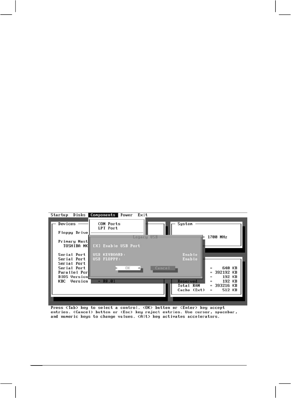
Pointing Device
This item enables or disables the touchpad. A checkmark (9) indicates
enabled, while an underline (_) indicates disabled. The default setting is
disabled.
LPT Port
This item configures the parallel port of the computer.
Setup Configuration Utility (SCU)
5-12
Port Address sets the I/O address and the interrupt request line
settings of the parallel port. The options are None; LPT1, 378, IRQ
7; LPT2, 278, IRQ 5;and LPT3, 3BC, IRQ 7. Default setting is LPT1,
378, IRQ 7.
Port Definition sets the operating mode for the parallel port
according to the type of the parallel device to be connected. Your
system supports EPP (Enhanced Parallel Port) and ECP (Extended
Capabilities Port) standards, which turn the standard parallel port
into a high-speed bi-directional peripheral port. The options are
Standard AT (Centronics), Bidirectional (PS-2), Enhanced Parallel
(EPP), and Extended Capabilities (ECP). Default setting is
Extended Capabilities (ECP). This item is not valid for setting if the
Port Address item is set to None.
DMA Setting For ECP Mode sets the DMA (Direct Memory
Access) channel of the ECP mode. The options are DMA 1 and DMA
3. Default setting is DMA 3. This item is not valid for setting if the
Port Definition item is not set to Extended Capabilities (ECP).
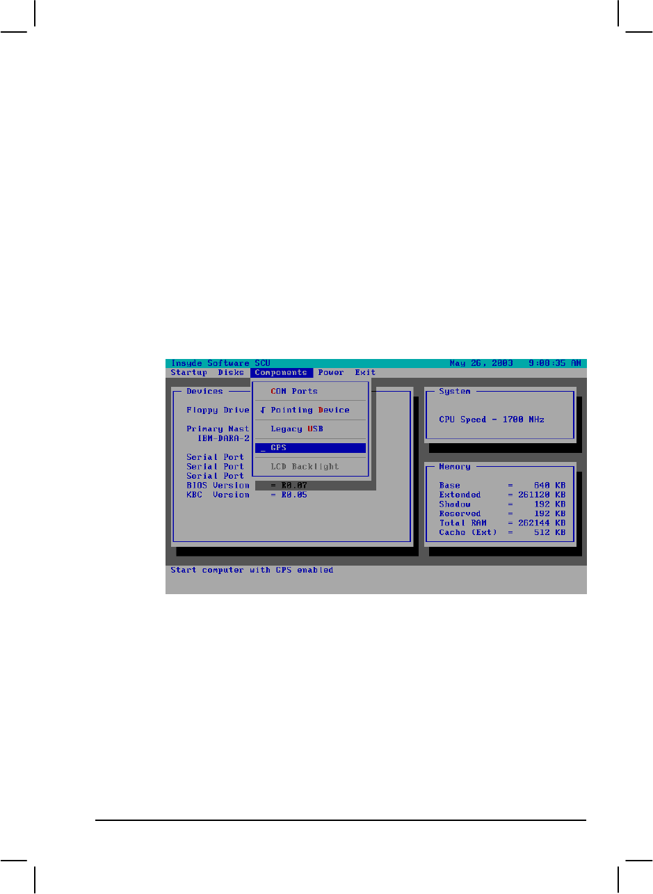
Legacy USB
This item enables or disables the system’s support for the USB port in
DOS mode.
Setup Configuration Utility (SCU) 5-13
The Enable USB Port sub-item enables or disables the USB port in
DOS mode. The options are enable and disable. A [X] mark indicates
enable, while blank [ ] indicates disable. Default setting is enable.
The USB Keyboard sub-item enables or disables the USB
keyboard in DOS mode. The options are Enable and Disable.
Default setting is Enable. This item is not valid for setting if the
Enable USB Port sub-item is disabled.
The USB Floppy sub-item enables or disables the USB floppy drive
in DOS mode. The options are Enable and Disable. Default setting is
Enable. This item is not valid for setting if the Enable USB Port
sub-item is disabled.
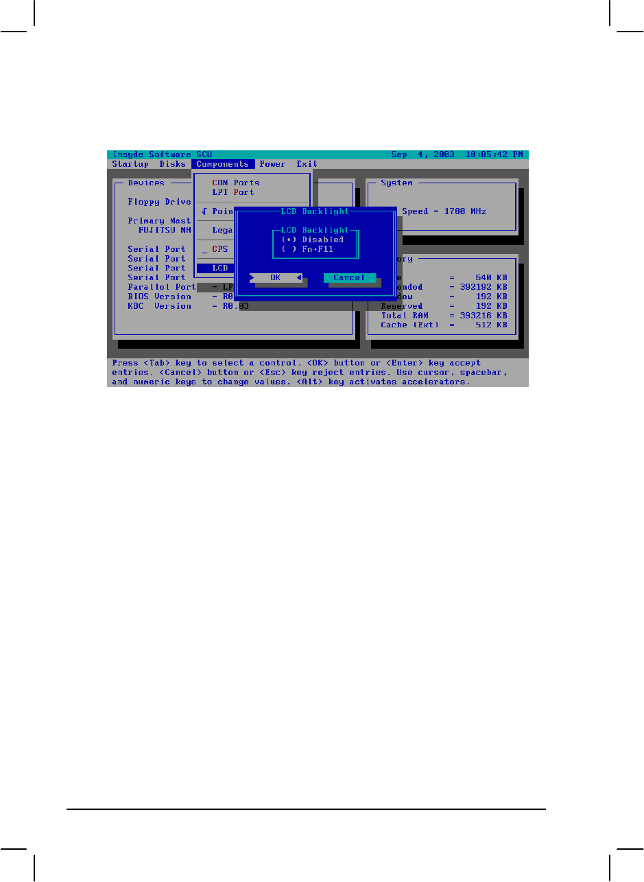
GPS
Setup Configuration Utility (SCU)5-14
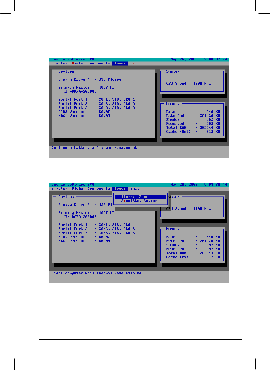
LCD Backlight
Fn+F11: Enabled/Disabled the LCD Backlight On/Off.
Setup Configuration Utility (SCU) 5-15
Power Menu
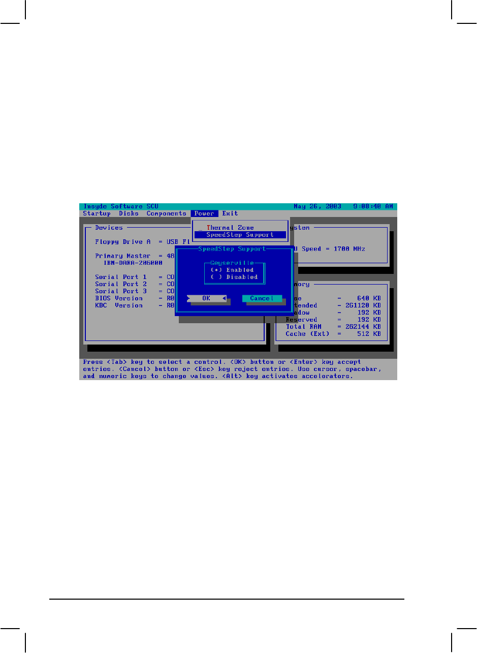
Thermal Zone
Setup Configuration Utility (SCU)5-16
SpeedStep Support
Enables or disables the Geyserville feature of the CPU. The Geyserville
feature helps conserve battery life by decreasing the CPU’s running speed
under certain conditions while still maintaining a high performance. If this
item is enabled, the CPU will automatically change its speed whenever
necessary based on the “Power Scheme” setting in Windows’s Control Panel.
If this item is disabled, the CPU will always run in the lowest speed (600
MHz).
Setup Configuration Utility (SCU) 5-17
Exit Menu
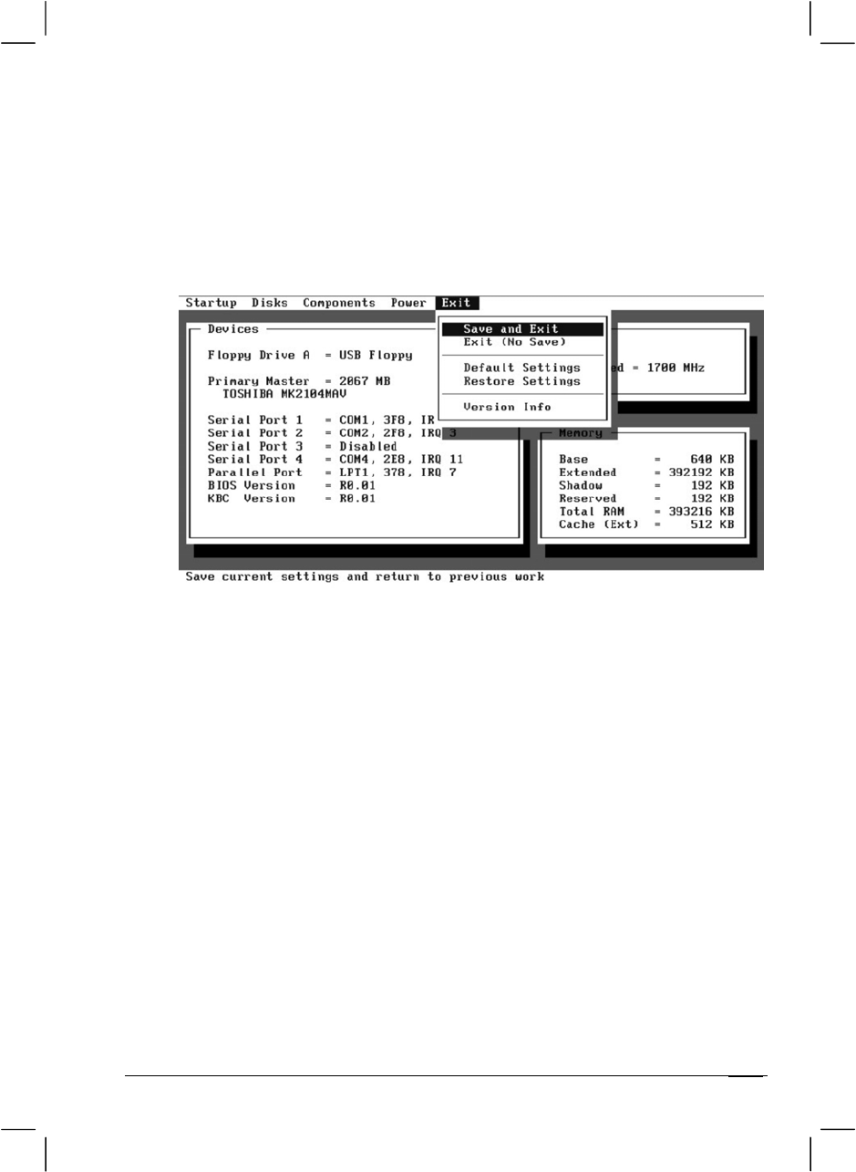
The Exit menu allows you to leave the SCU program. After finished with
your settings, you must save and exit so that the new settings can take
effect.
Save and Exit saves the changes you have made and exit the SCU
program.
Exit (No Save) exits the SCU program without saving the changes you
have made.
Default Settings loads factory default values for all the items.
Restore Settings restores previous values for all the items.
Version Info displays the BIOS version information.

Setup Configuration Utility (SCU)5-18

CHAPTER 6
Installing Software Drivers
To take full advantage of the unique features of your computer, some
operating systems require custom software, known as drivers, to be
installed.
If you purchased the computer with Windows pre-installed, your dealer
may have already installed the drivers. If not, you need to install the
drivers using the driver CD supplied with your computer.
This chapter describes how to install the drivers.
6-2 Installing Software Drivers
How to Use the Driver CD
NOTES:
•The drivers may have been updated after this manual was published. For driver
upgrade, please contact your dealer.
•You can always find README or document files on the driver CD. These files
contain the latest information from the software supplier. Please read the files
together with this chapter.
•This driver CD supports Windows 2000 and Windows XP only.
•The available items may differ according to your computer model and operation
system.
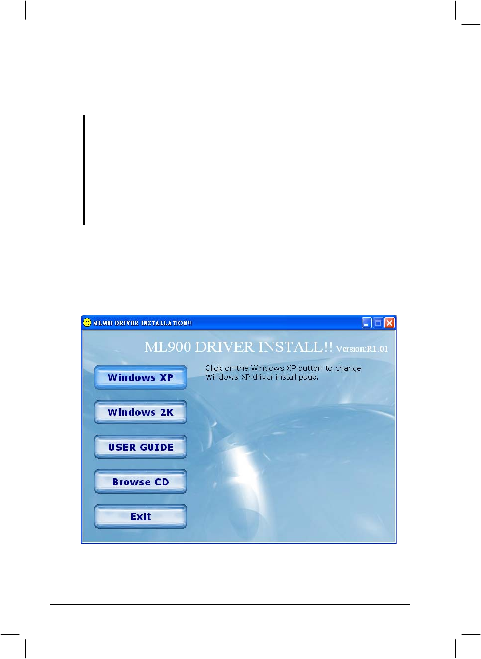
An autorun program is provided on the driver CD to help you easily
install the drivers. As you insert the driver CD, the autorun program
automatically starts. If you need to start the program manually, run the
Autorun.exe program from the Setup directory of the driver CD.
The main screen appears as shown next:
Installing Software Drivers 6-3
Installing Drivers for Windows 2000
To set up the necessary drivers for Windows 2000, click on “Windows
2K” on the initial screen. The following screen appears:
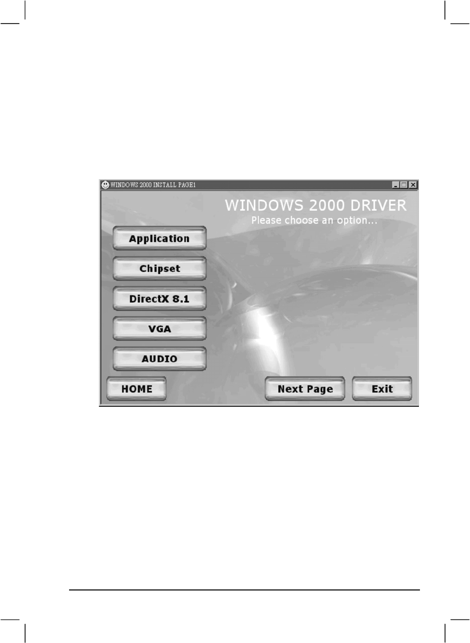
Drivers on the First Page
To install the necessary driver, just click on the particular option and
follow the onscreen instructions to continue and complete installation.
Application Installs the Intel® Application Accelerator to improve
performance of the storage sub-system and overall
system performance. This software delivers improved
performance through several ingredient technologies
(components).
Chipset Ensures the full function of the following drivers.
Install this main chipset driver before installing the
device drivers.
6-4 Installing Software Drivers
DirectX 8.1 Allows you to take full advantage of the multimedia
applications.
VGA Allows you to select high-resolution displays with
richer colors. It can drive LCD displays as well as
CRT displays.
Audio Allows you to take full advantage of the audio
subsystem.
Upon clicking “Next Page,” the following screen appears:
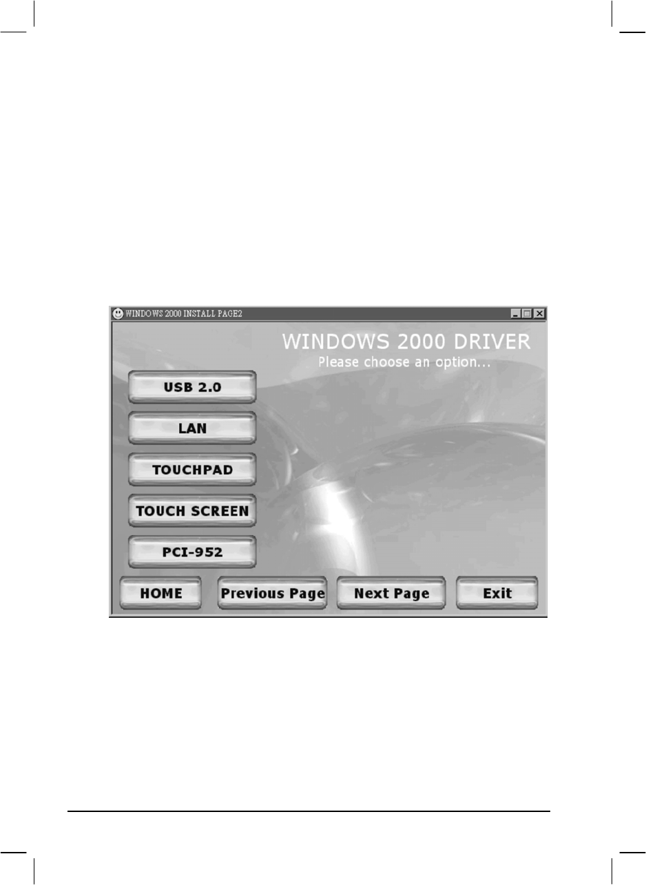
Drivers on the Second Page
USB 2.0 Allows your system to connect to USB 2.0 devices.
LAN Allows you to use the network function of the
computer.
Touchpad Allows you to take full advantage of the touchpad and
the scroll button features.
Touchscreen Allows you to use your fingers as a pointing device on
the LCD screen (refer to the next section for further
instructions).
Installing Software Drivers 6-5
PCI-952 Shows you the instructions on installing the driver that
allows you to use the optional wireless modem and
GPS features to transmit information wirelessly.
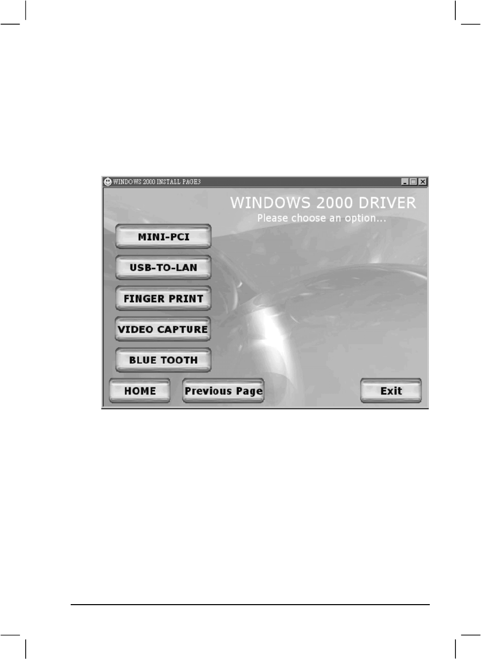
Upon clicking “Next Page,” the following screen appears:
Drivers on the Third Page
Mini-PCI Shows you the instructions on installing the WLAN
driver that allows you to use the internal Mini PCI
WLAN card.
USB-to-LAN Allows you to use the network function of the
computer when the optional docking station is
connected.
Fingerprint Shows you the instructions on installing the driver that
allows you to use the fingerprint recognition system
and its application software.

6-6Installing Software Drivers
Video Capture Shows you the instructions on installing the driver that
allows you to connect a video capture device through
the AV input port.
Bluetooth Allows you to use the bluetooth port to connect to
bluetooth-compliant devices.
Touchscreen Driver
To install the touch screen driver, perform the following:
1. Insert the driver CD into the drive.
2. Click on “Windows 2K”, then “Touchscreen” and follow the
onscreen instructions to continue.
3. When finished installing, select “Yes” to reboot your system. The
driver should now be loaded.
4. After the system has finished rebooting, click on the “PenMount
Monitor” icon located on the taskbar to bring up the “PenMount
Control Panel”.
5. Select the “Standard Calibration” folder and click on “OK.”
6. Click on “Advanced Calibration” button.
7. Click on the four sides (points) and the plus-sign “+” on the screen to
calibrate your touchscreen for use on the computer.