Motorola Solutions 89FT7614 Mini-PCI Transmitter Card User Manual
Motorola Solutions, Inc. Mini-PCI Transmitter Card
UserManual.wiki
>
Motorola Solutions
>
89FT7614 User Manual
Users Manual
Navigation menu
Upload a User Manual
Namespaces
Wiki Guide
HTML
PDF
Info
Views
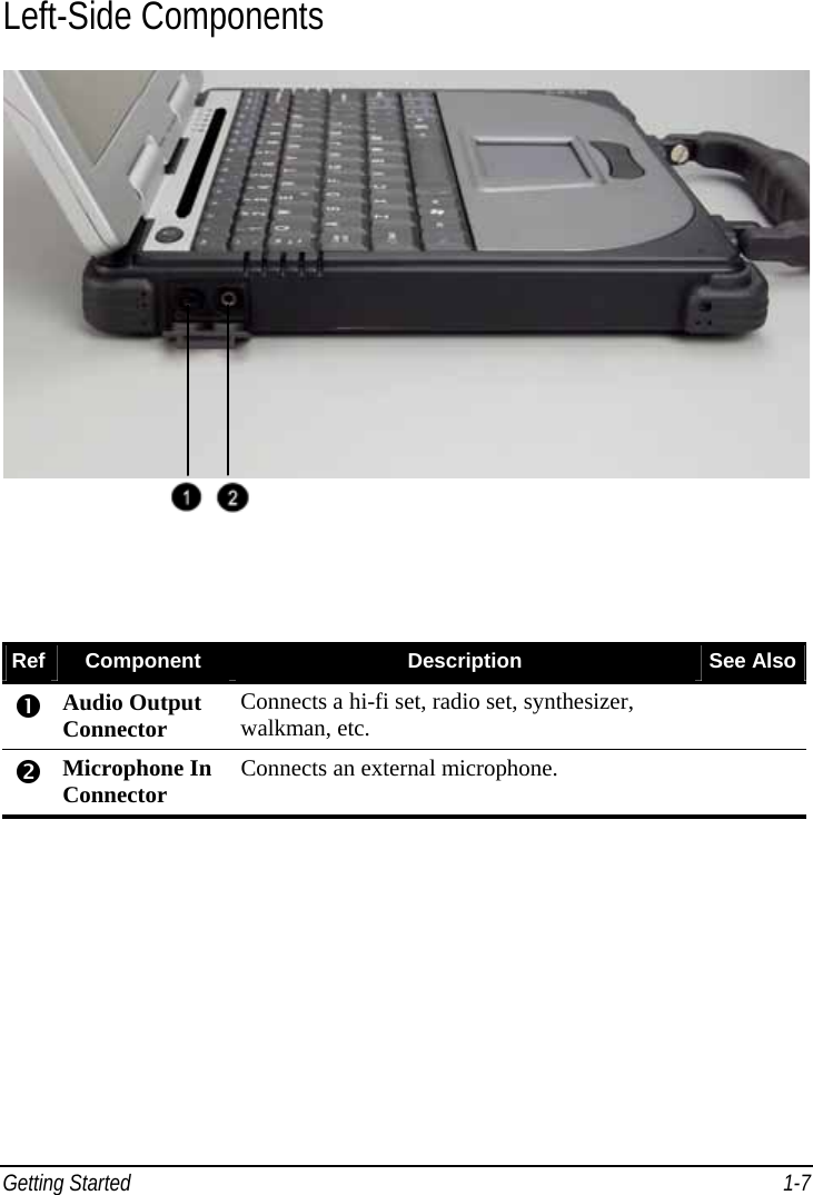
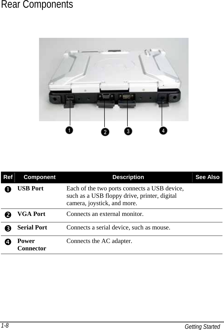
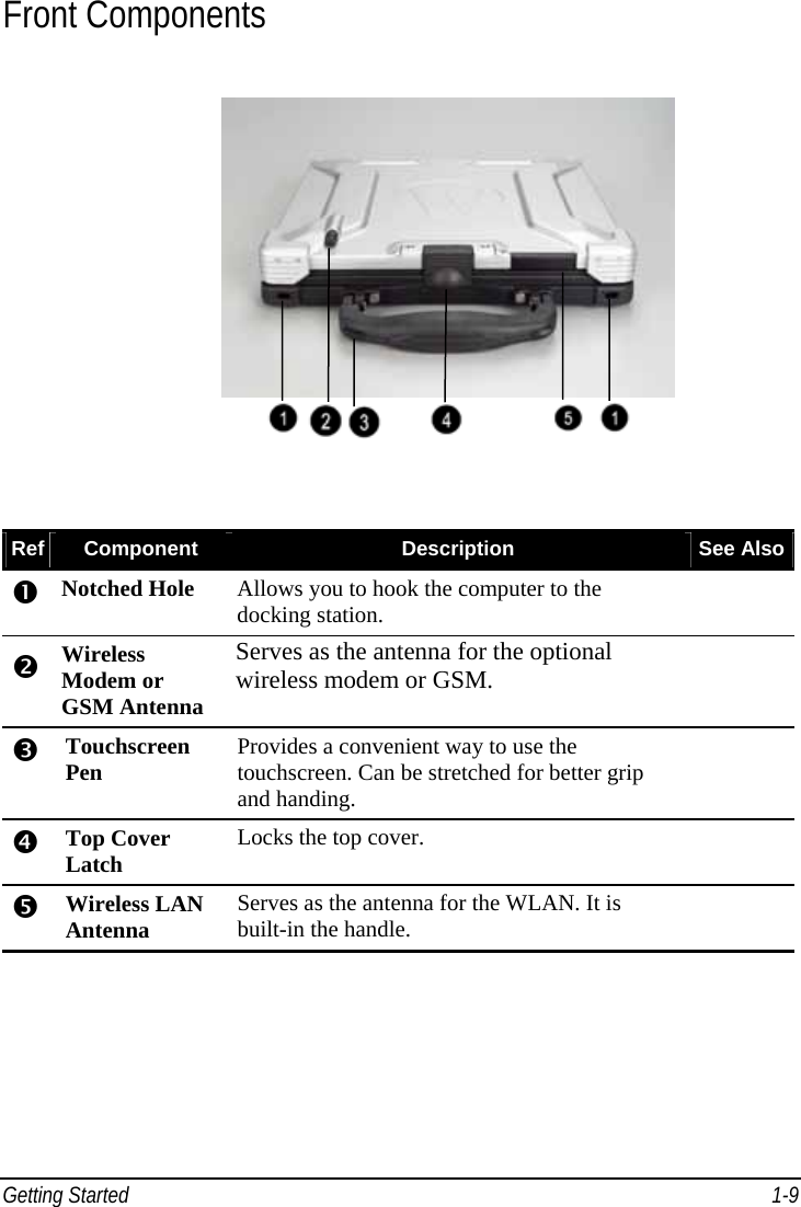
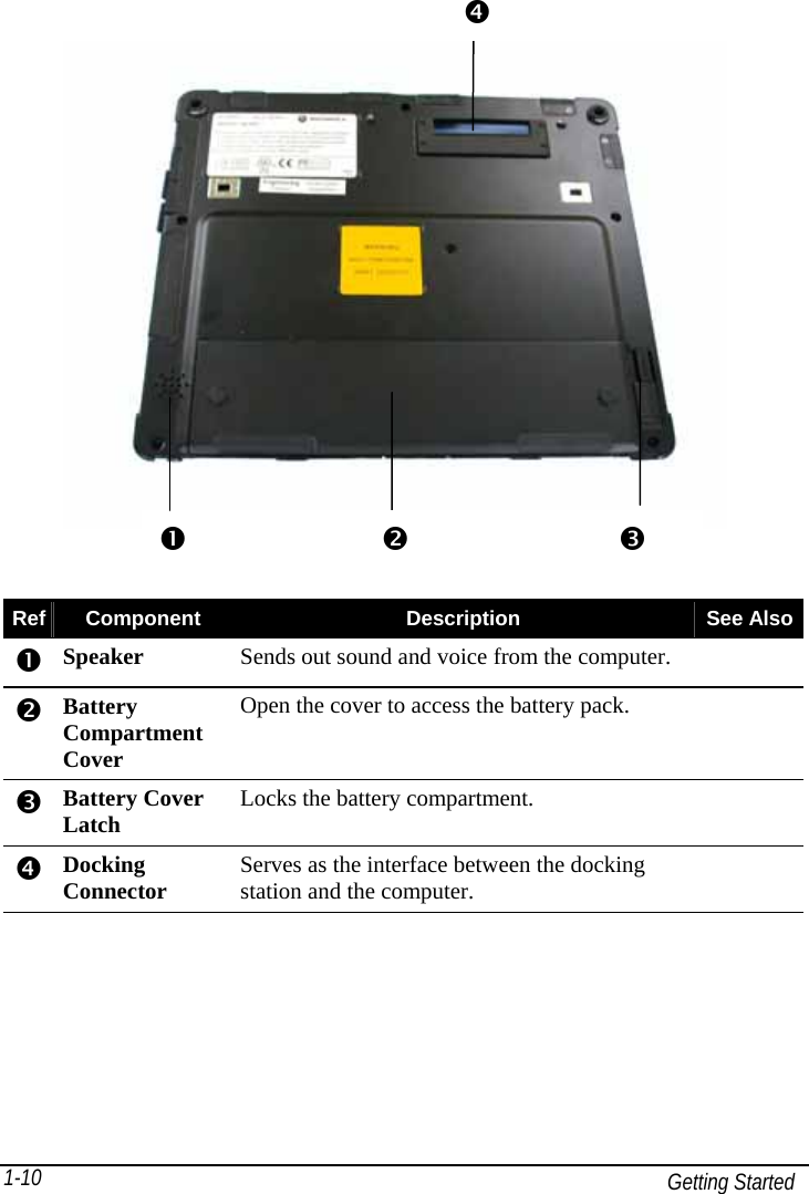
User Manual
Discussion / Help
Navigation
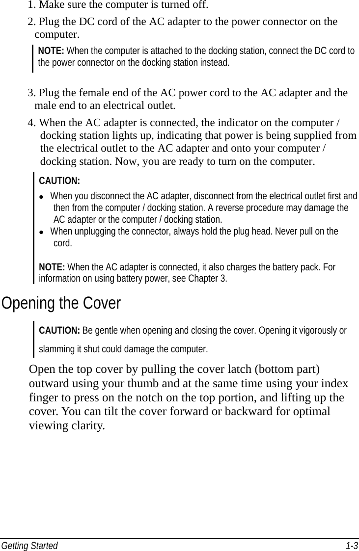
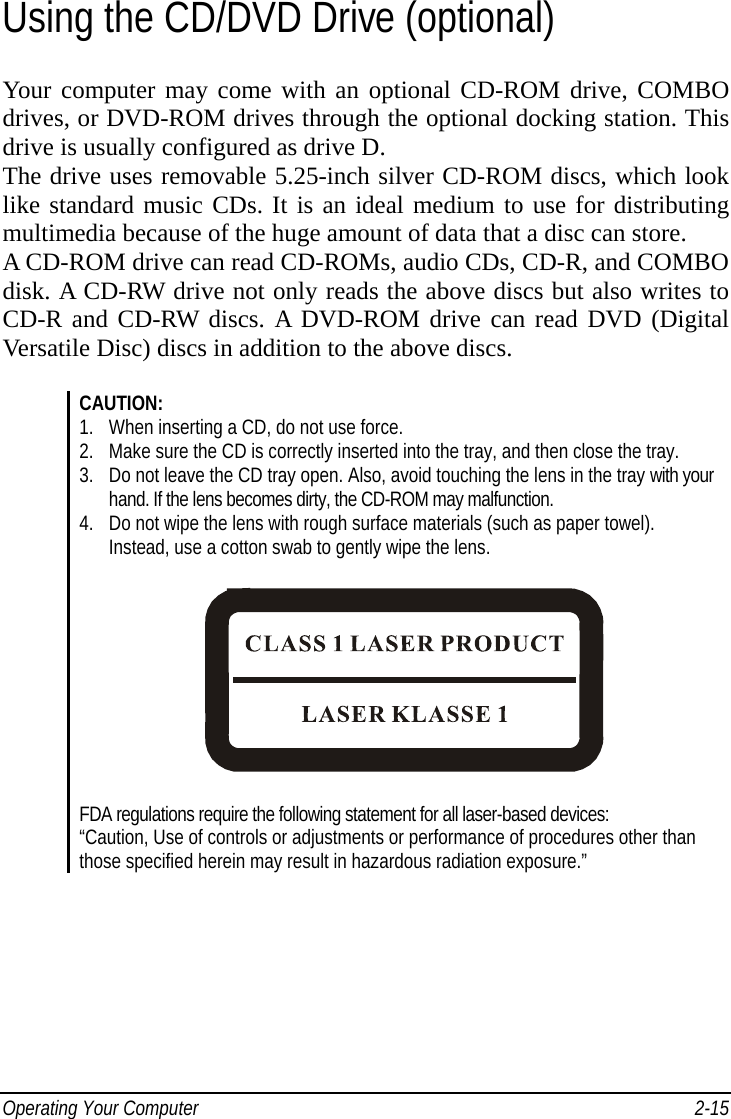

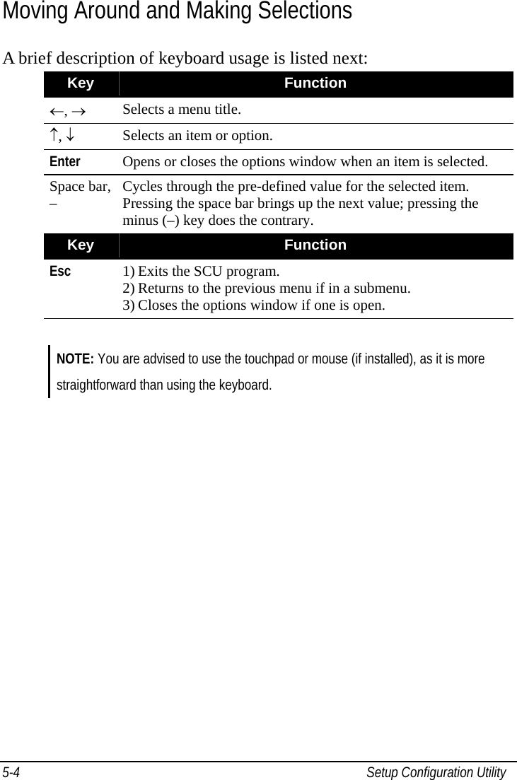
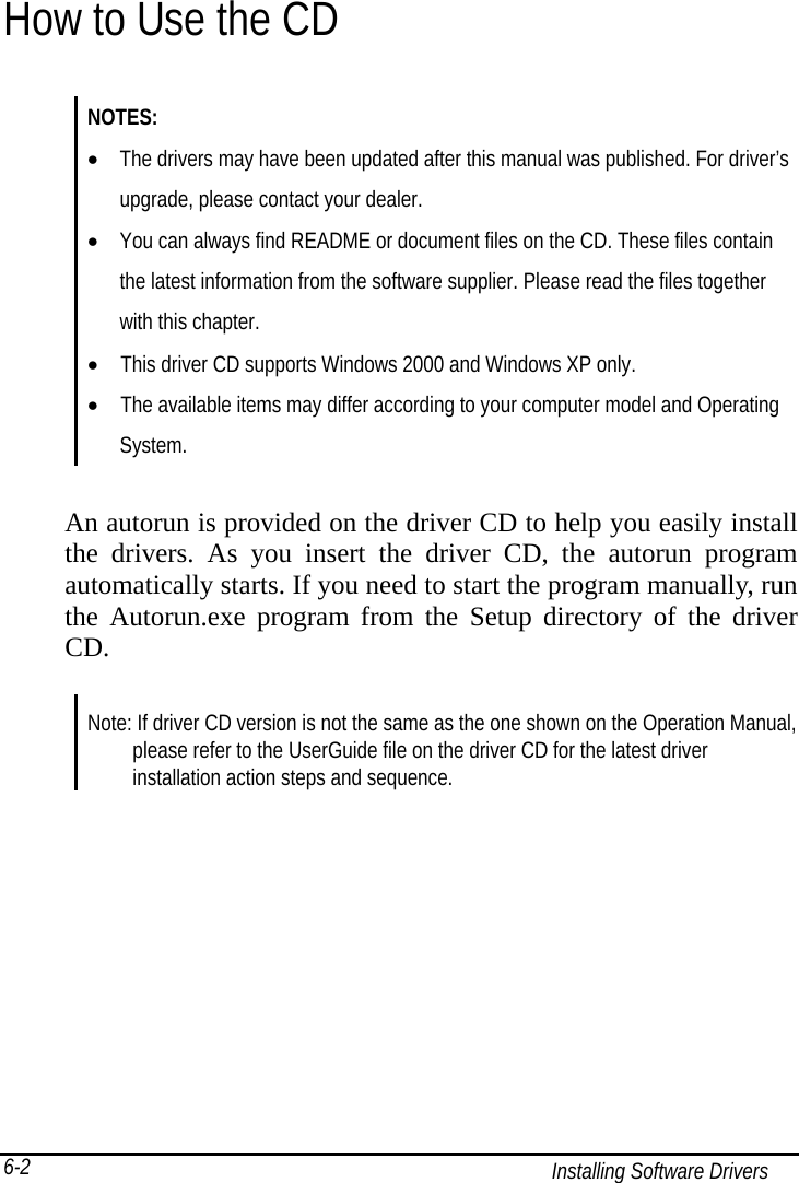
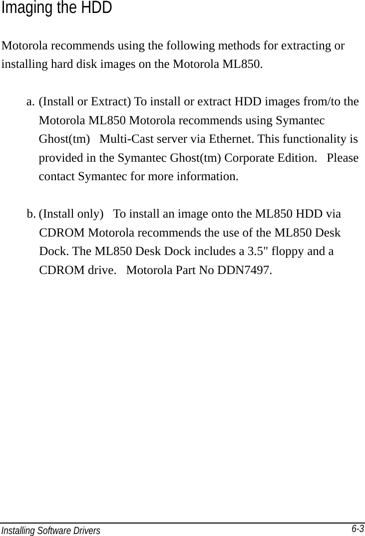
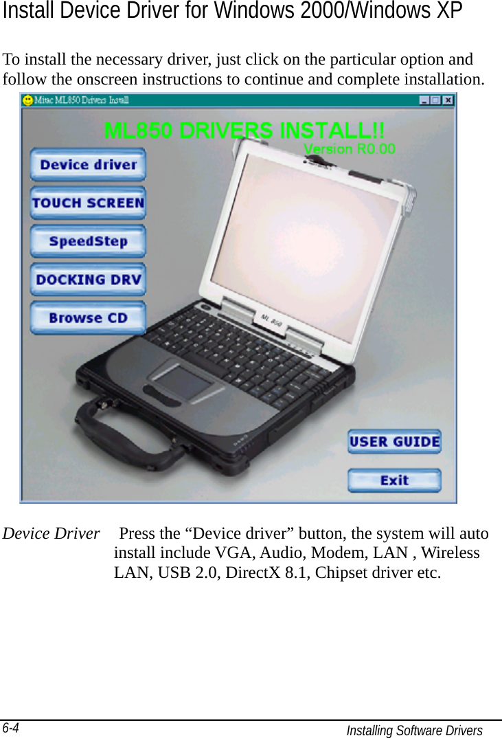
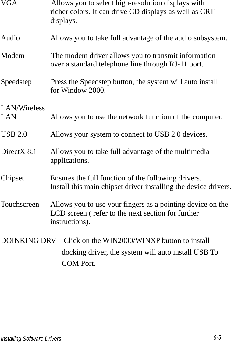
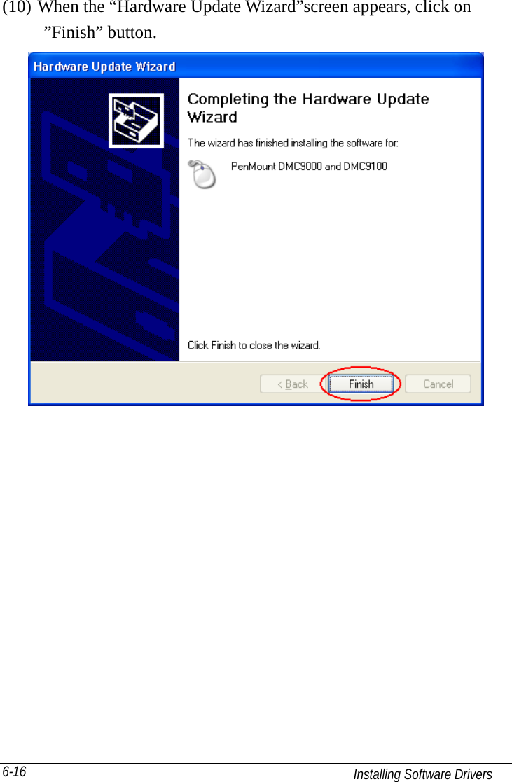
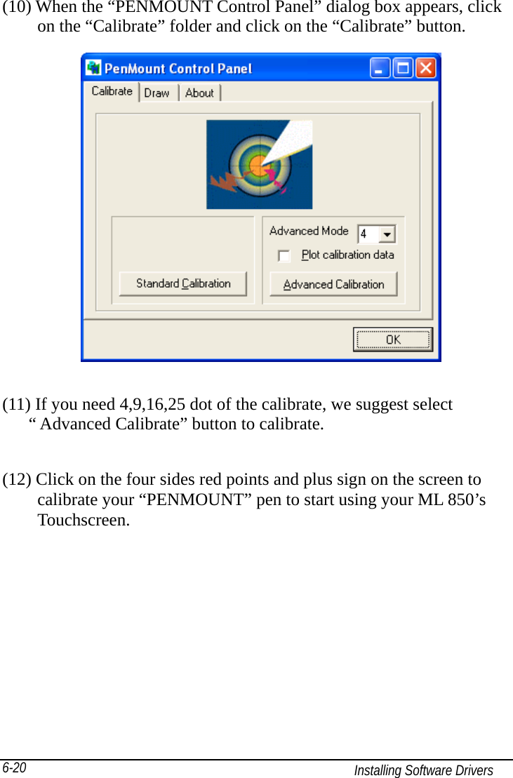
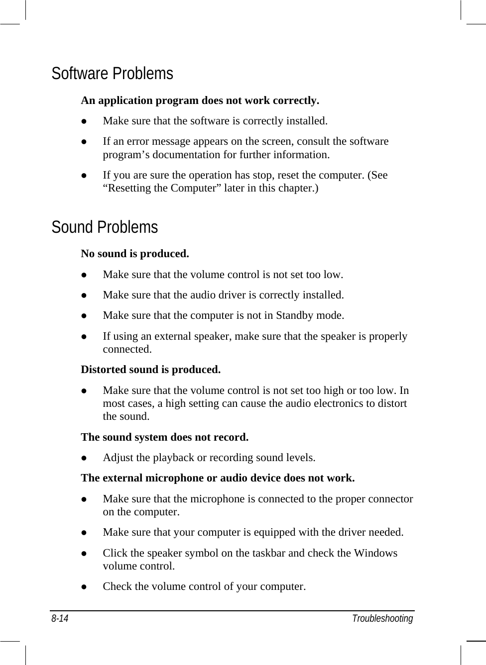
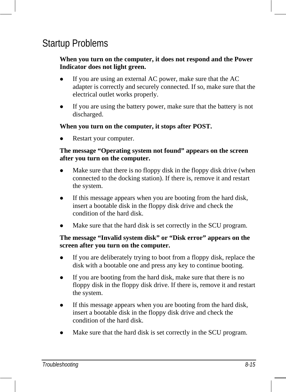
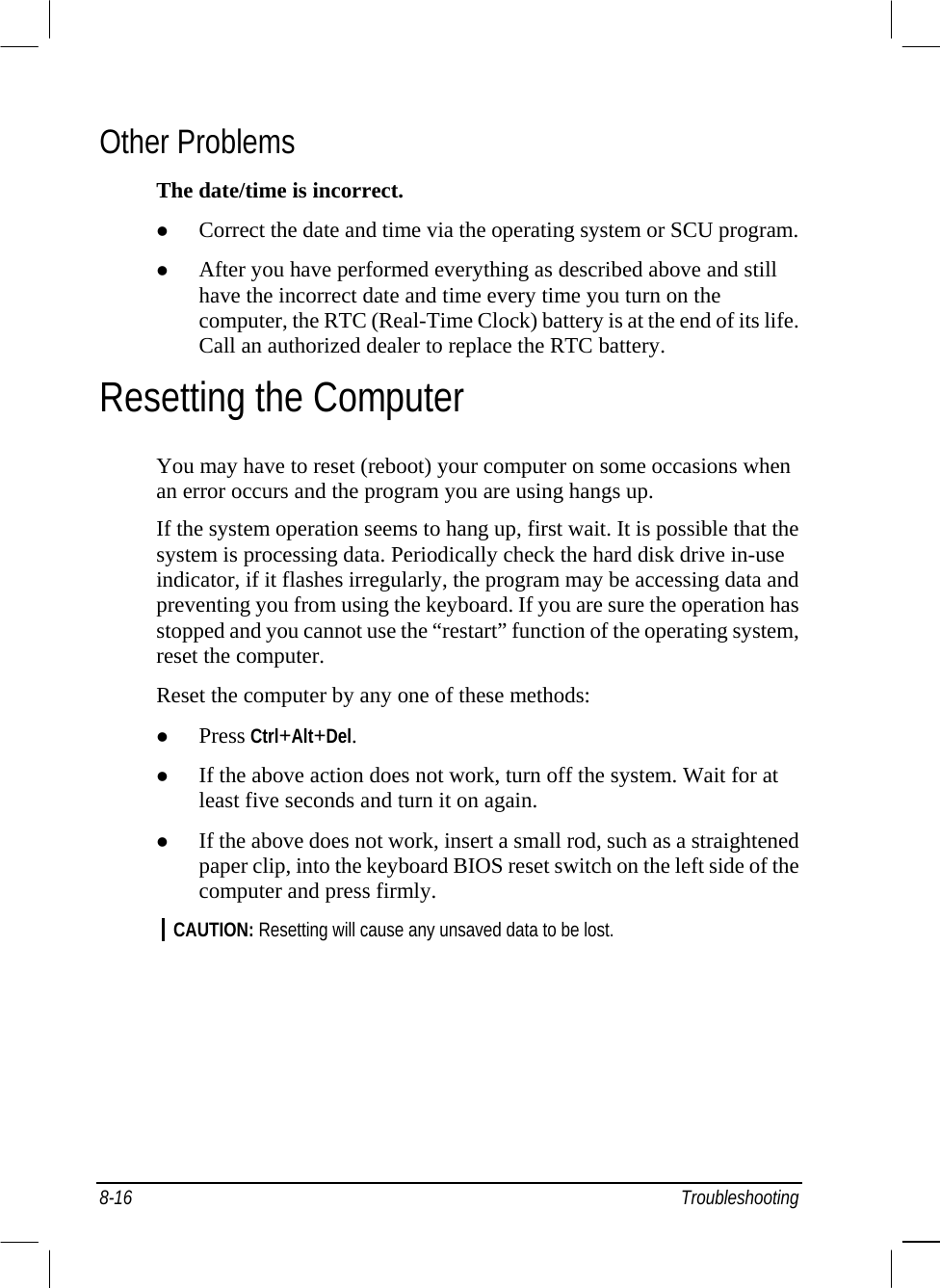
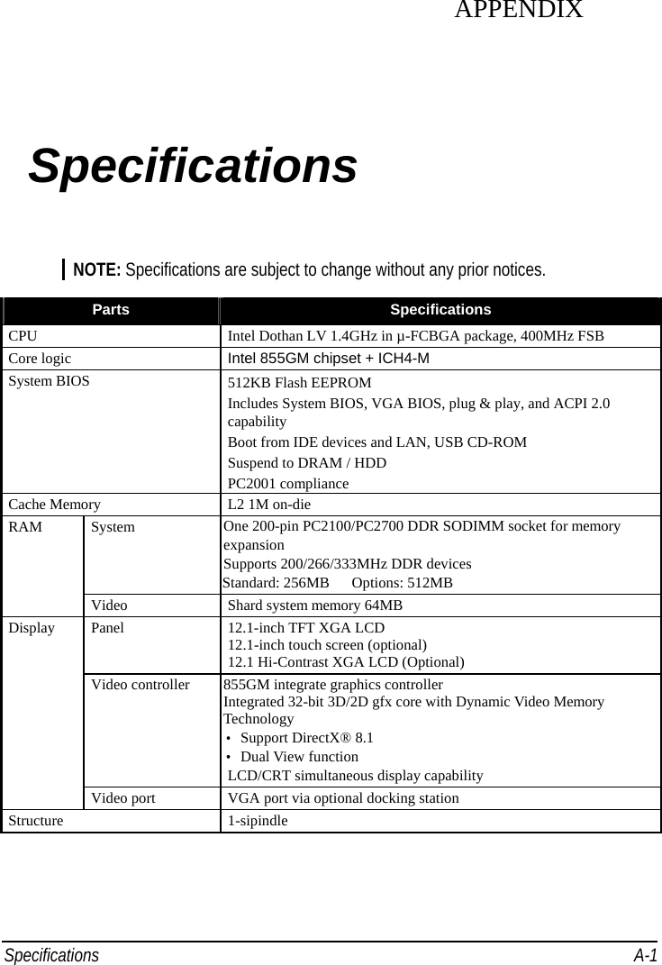
![Installing Software Drivers 6-15(8) When the “Hardware Update Wizard” appears, click on “ Install the software automatically [Recommand], then click on ”Next”. (9) When the “Hardware Installation” screen appears, click on ”Continue Anyway”.](https://usermanual.wiki/Motorola-Solutions/89FT7614/User-Guide-527184-Page-105.png)