Motorola Solutions 89FT7622 5.7GHz Fixed Wireless (ISM) User Manual Exhibit D Users Manual Part 3 per 2 1033 b3
Motorola Solutions, Inc. 5.7GHz Fixed Wireless (ISM) Exhibit D Users Manual Part 3 per 2 1033 b3
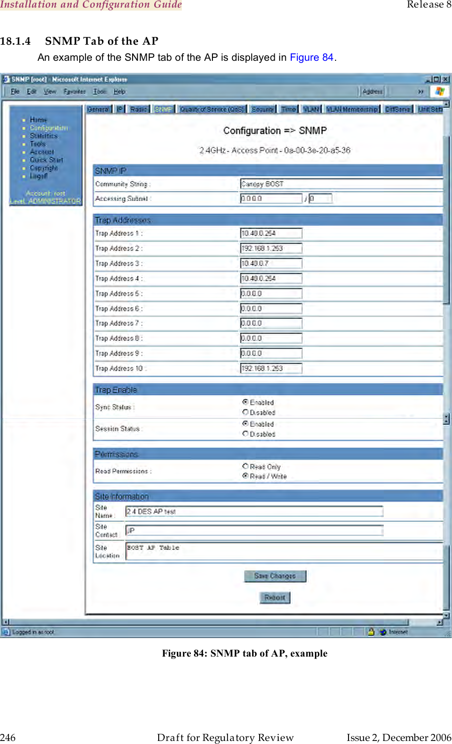
Contents
- 1. Exhibit D Users Manual Part 1 per 2 1033 b3
- 2. Exhibit D Users Manual Part 2 per 2 1033 b3
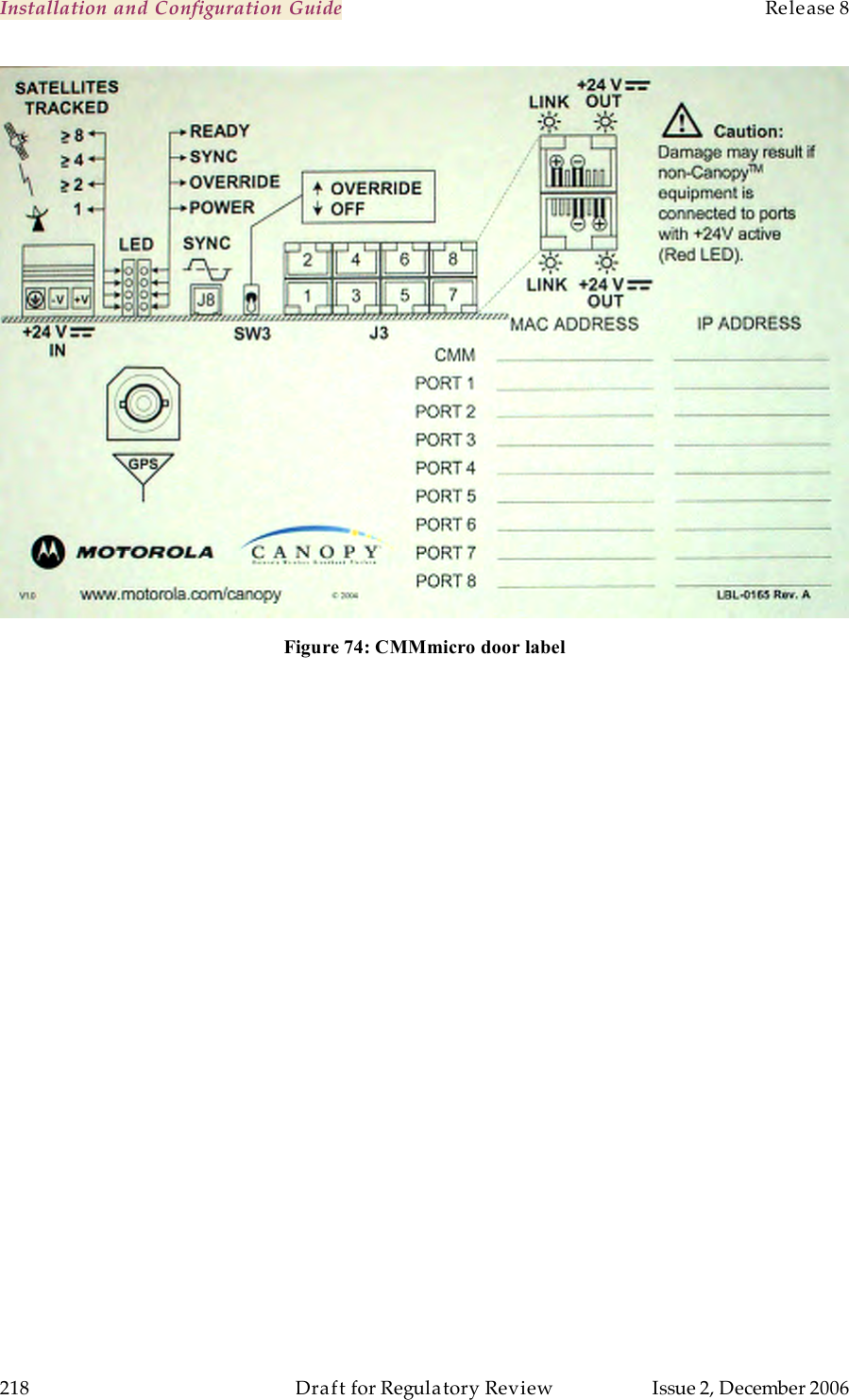
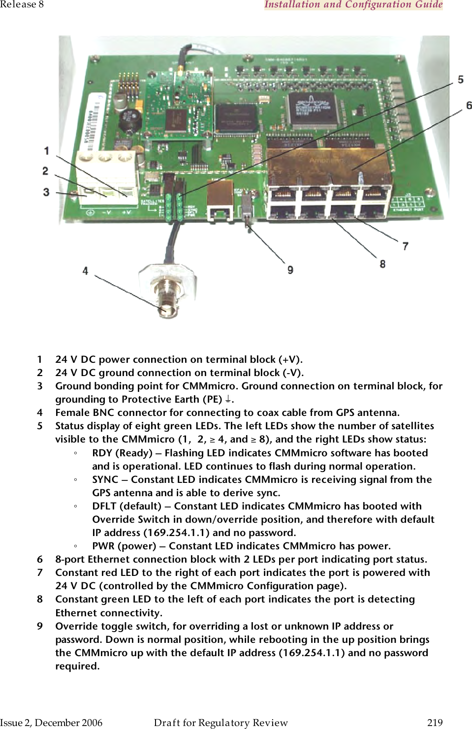
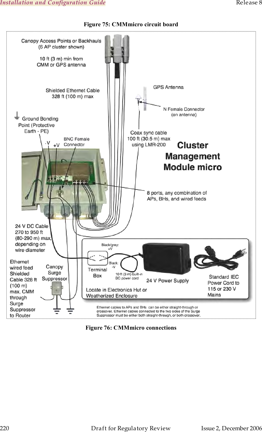
- 3. Exhibit D Users Manual Part 3 per 2 1033 b3
- 4. Exhibit D Users Manual Part 4 per 2 1033 b3
- 5. Exhibit D Users Manual Part 5 per 2 1033 b3
- 6. Exhibit D Users Manual Part 6 per 2 1033 b3
- 7. Exhibit D Users Manual Part 7 per 2 1033 b3
- 8. Exhibit D Users Manual Part 8 per 2 1033 b3
- 9. Exhibit D Users Manual Part 9 per 2 1033 b3
- 10. Users Manual
Exhibit D Users Manual Part 3 per 2 1033 b3