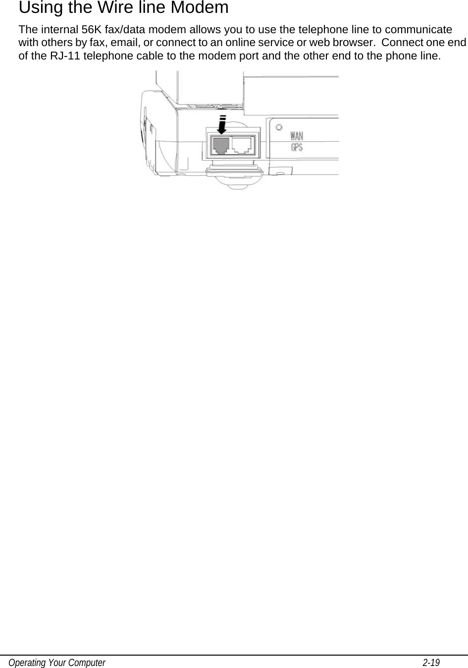
Motorola Solutions 89FT7626 Mobile Computer with Wireless Modem Module User Manual ML910 CH0 new version 9 18 07
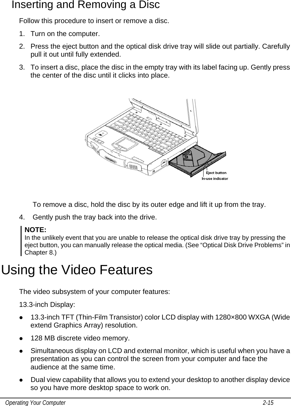
Motorola Solutions, Inc. Mobile Computer with Wireless Modem Module ML910 CH0 new version 9 18 07
Contents
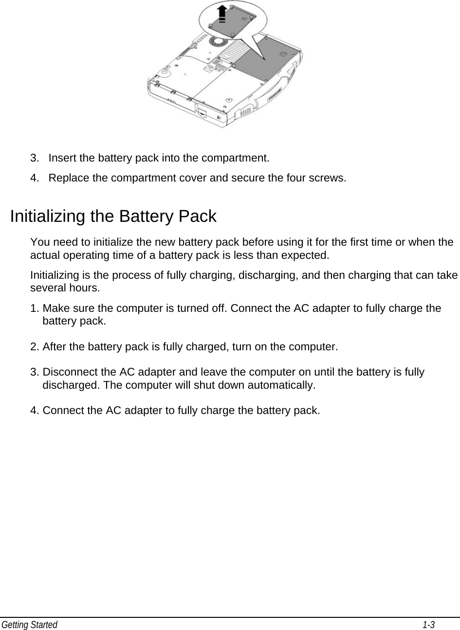
- 1. Users Manual 1
- 2. Users Manual 2
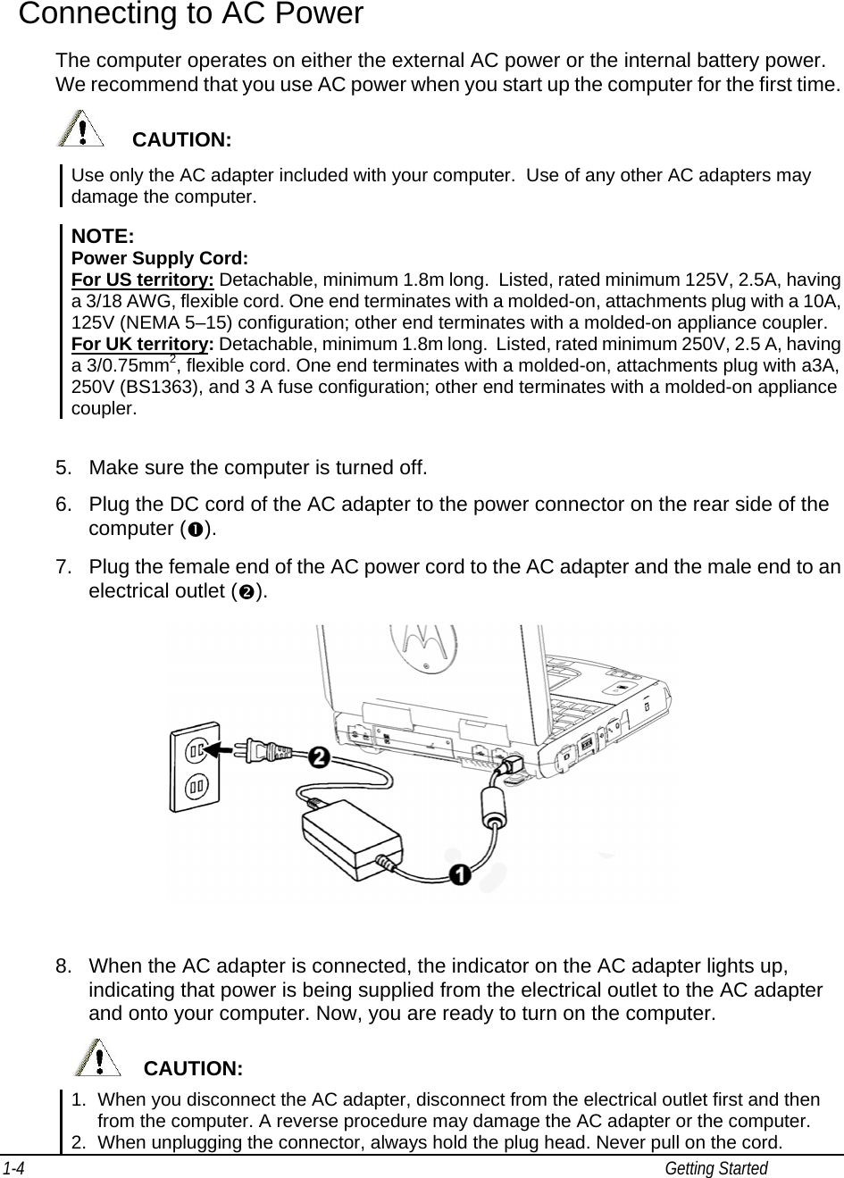
Users Manual 1