Motorola Solutions 89FT7627 Mobile Computer with WLANabg Module User Manual ML910 CH0 new version 9 18 07
Motorola Solutions, Inc. Mobile Computer with WLANabg Module ML910 CH0 new version 9 18 07
Contents
- 1. Users Manual 1
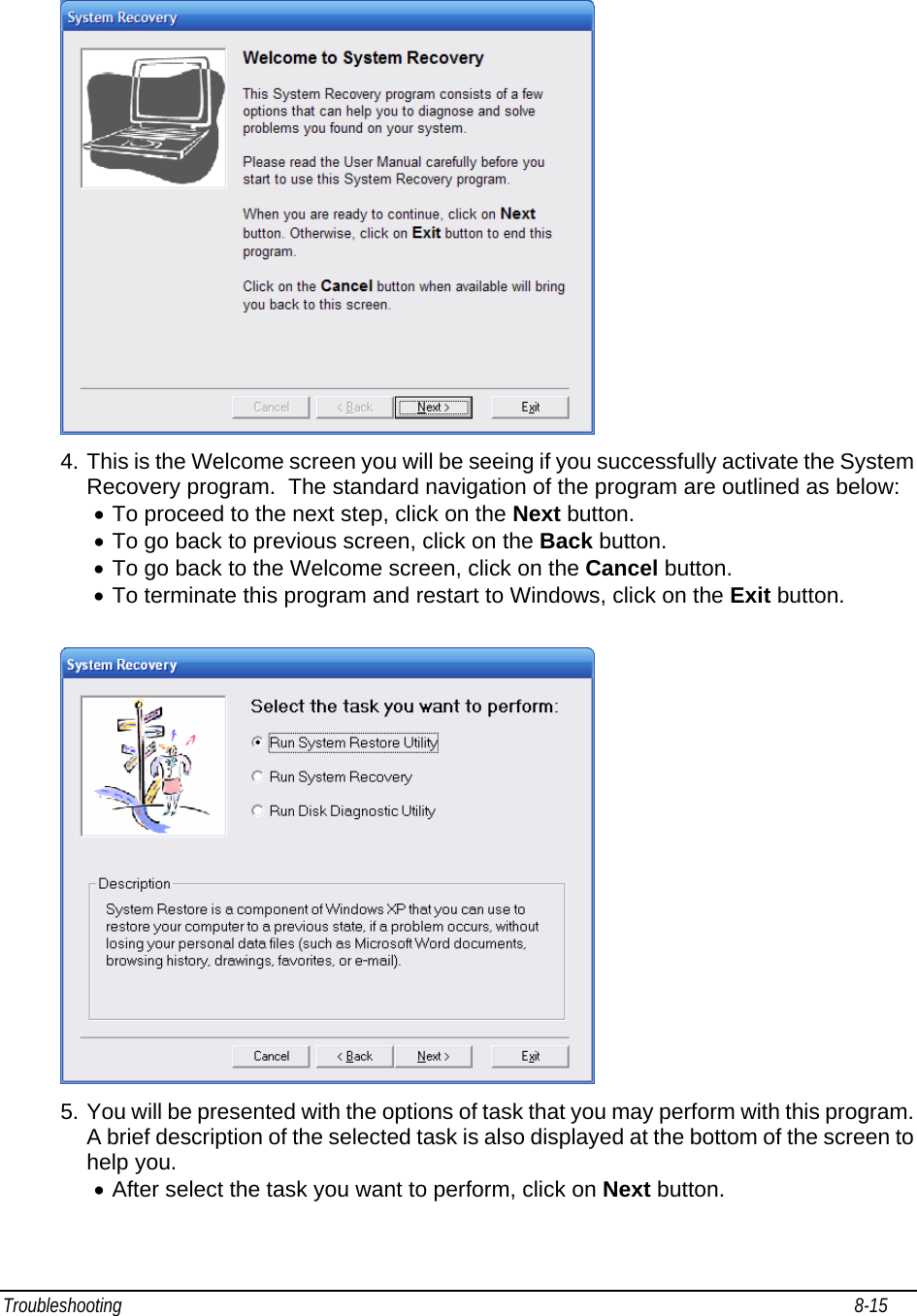
- 2. Users Manual 2
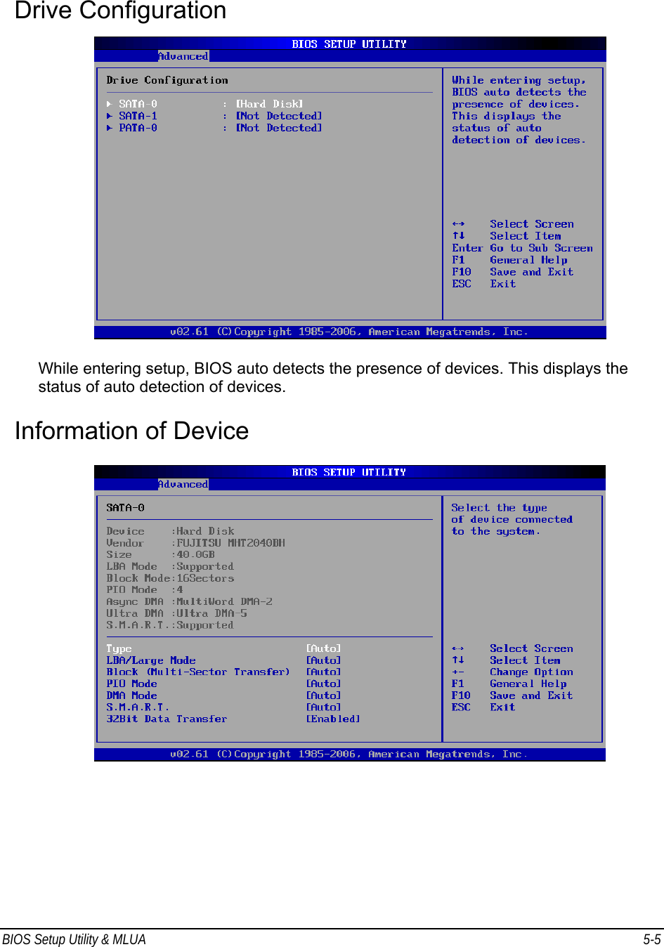
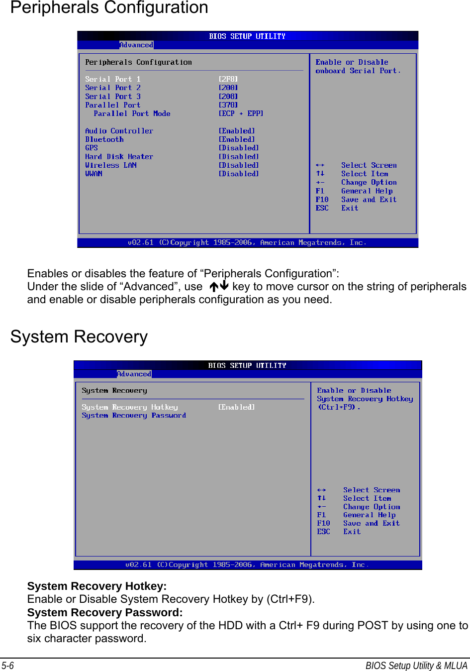
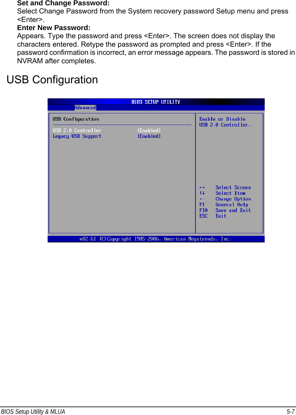
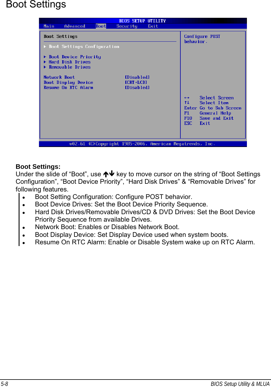
Users Manual 2

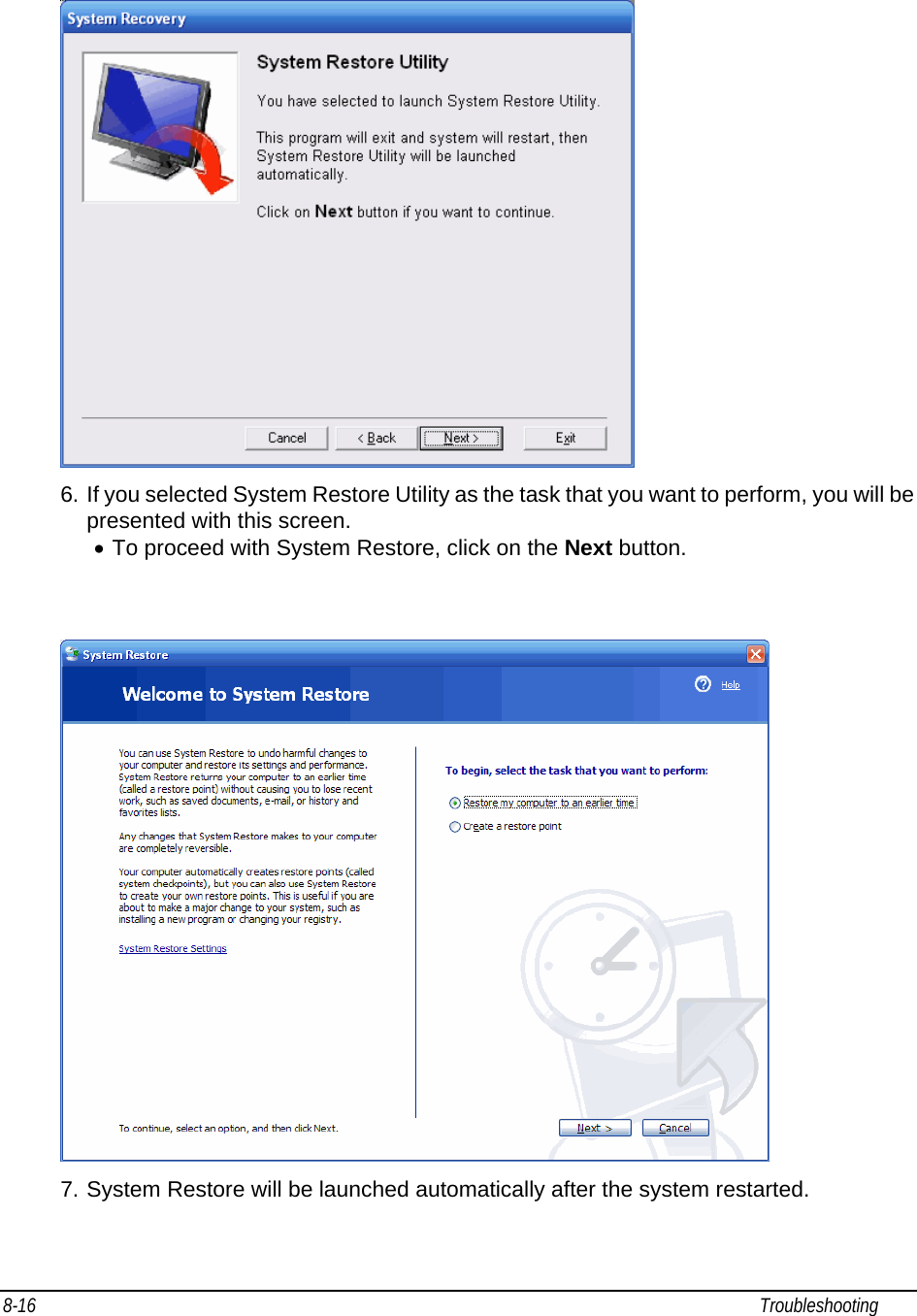
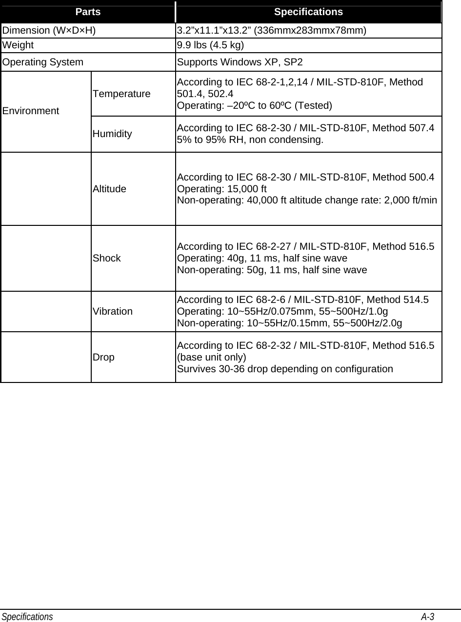
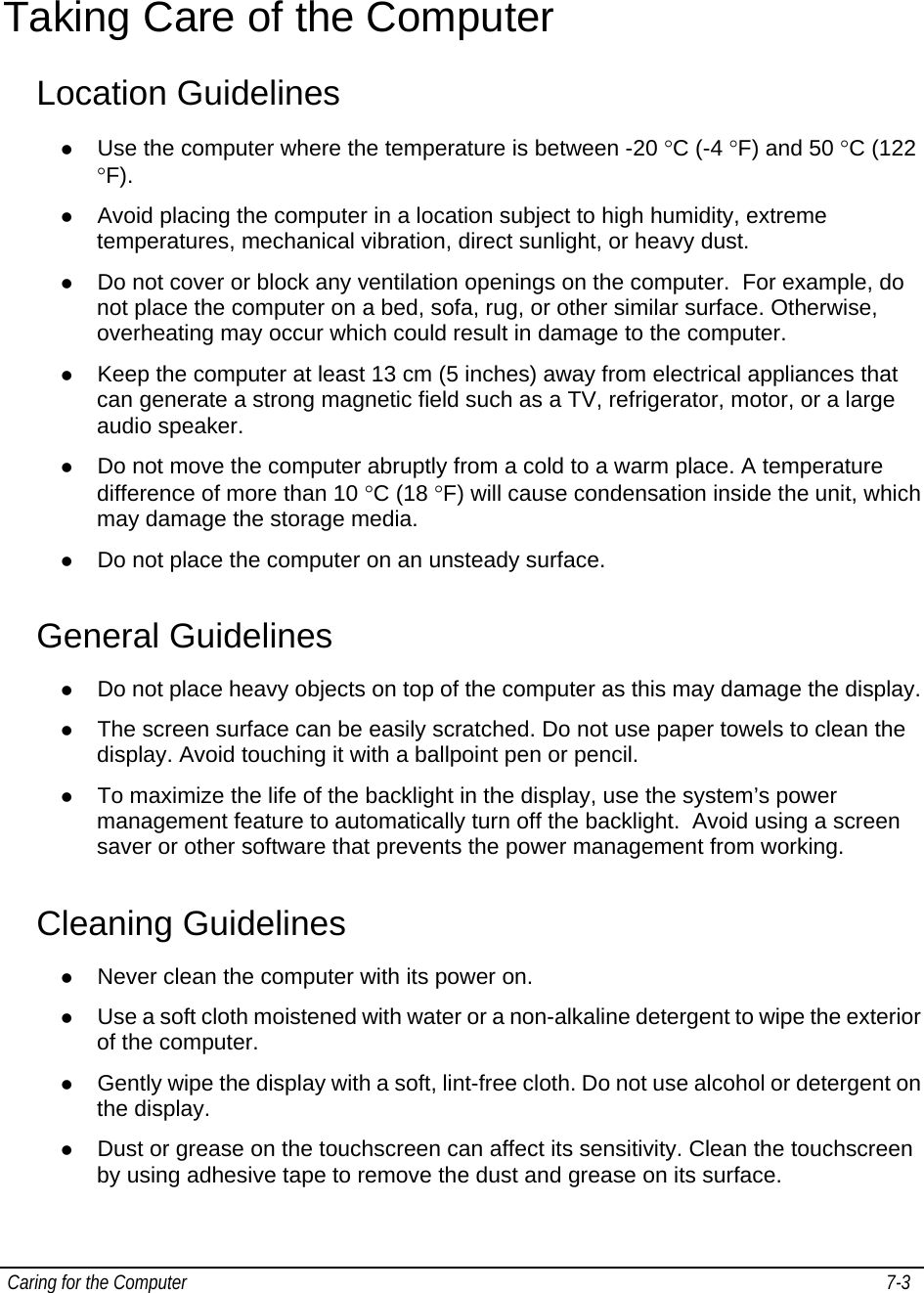
![BIOS Setup Utility & MLUA 5-11 Enter New Password: Appear Type the password and press <Enter>. The screen does not display the characters entered. Retype the password as prompted and press <Enter>. If the password confirmation is incorrect, an error message appears. The password is stored in NVRAM after completes. Change User Password: Select Change User Password from the Security Setup menu and press <Enter>. Enter New Password: Appear Type the password and press <Enter>. The screen does not display the characters entered. Retype the password as prompted and press <Enter>. If the password confirmation is incorrect, an error message appears. The password is stored in NVRAM after completes. Clear User Password: Select Clear User Password from the Security Setup menu and press <Enter>. Clear New Password: [Ok] [Cancel] Appear Type the password and press <Enter>. The screen does not display the characters entered. Retype the password as prompted and press <Enter>. If the password confirmation is incorrect, an error message appears. The password is stored in NVRAM after completes. Exit Options CAUTION: It will conflict with ML910™ Com Ports resource and there is a work-around to fix it if you use I/O resources is "2F8h","3F8h","2E8h" or "3E8h" to PCMCIA card.](https://usermanual.wiki/Motorola-Solutions/89FT7627.Users-Manual-2/User-Guide-851191-Page-10.png)

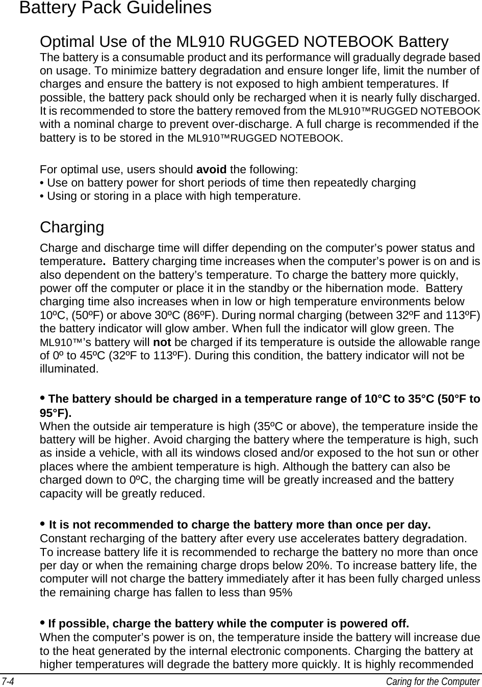
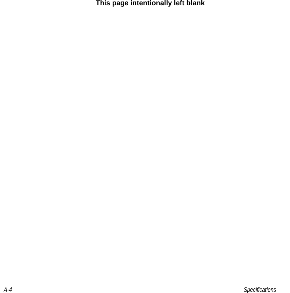
![Caring for the Computer 7-5 that you charge the battery while the computer is powered off. This allows for faster charging, less degradation, and longer battery life. Maximizing Battery Operation Time • Leave the computer off when not in use! • Decrease the internal LCD brightness by pressing FN + F5 Pressing Fn + F5 will lower the degree of brightness, thereby reducing the power consumption. • Before stepping away from your computer, place it in standby or hibernation mode Standby or hibernation mode will reduce power consumption. • To select Power Options: Click: [Start] - [Control Panel] - [Performance and Maintenance] - [Power Options], and select the desired power-saving setting. • Motorola recommends against using screen savers or applications that place a significant load on the CPU Some screen savers and applications place a large load on the CPU, producing a significant decrease in battery runtime even when the computer is not being used. • If possible remove unnecessary peripheral devices (USB devices, PC Cards, external mouse, etc.) when not in use. • For all other power-saving settings, please refer to the Power Management information in this section of the User Guide. Storage and Non Use for Extended Periods When the computer is not in use for an extended period (10 days or more): • Remove the battery from the computer with a remaining charge of 30% to 45%, and then store it in a cool, dark and dry place. If the battery pack is kept installed in the computer, it will discharge steadily even when the computer’s power is off. If this condition continues for a long period (10 days or more), the battery may over discharge, causing performance degradation. In addition, this degradation will accelerate if the unit is stored in any high temperature environment such as inside a vehicle with windows closed, exposed to direct sun or in any other environment where the temperature is high. Store the unit with battery pack where the temperature is within the range of 10°C to 30°C (50°F to 86°F). Never allow the temperature to exceed 60°C (140°F) or permanent damage may occur. If the battery has been stored out of the notebook computer, longer than 60 days, it should be checked for remaining charge condition. If below 20% remaining charge, the battery should be charged up to 30 to 45% before placing it back in storage.](https://usermanual.wiki/Motorola-Solutions/89FT7627.Users-Manual-2/User-Guide-851191-Page-28.png)