Motorola Solutions 92FT1628 Mobile Transmitter User Manual 92C58 B InstallWarnings
Motorola Solutions, Inc. Mobile Transmitter 92C58 B InstallWarnings
Contents
- 1. Users Manual
- 2. users manual
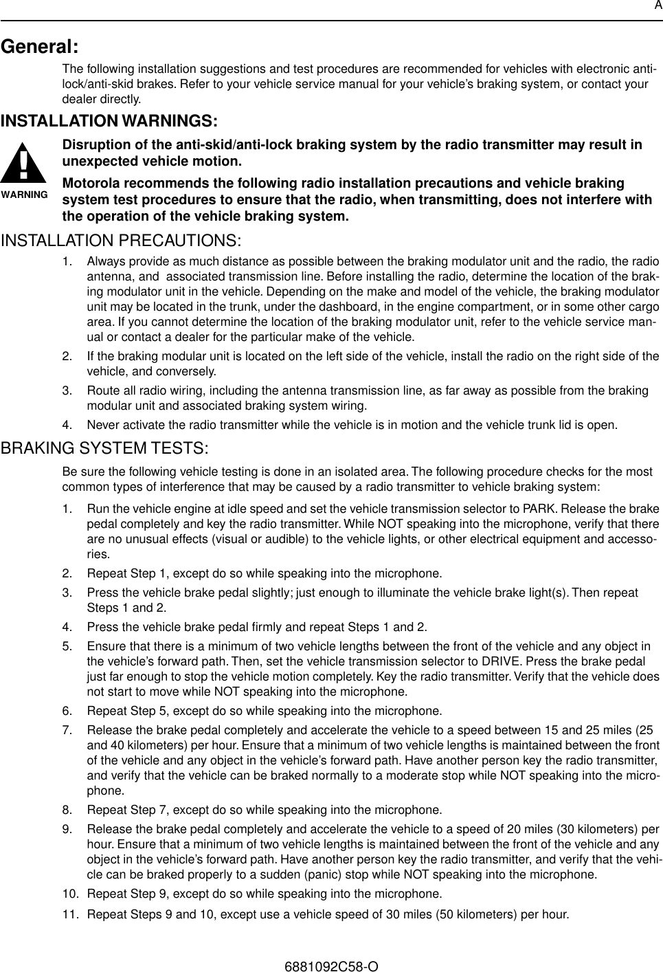
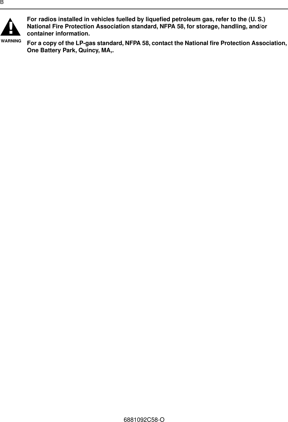
- 3. installation manual
- 4. antenna installation instructions
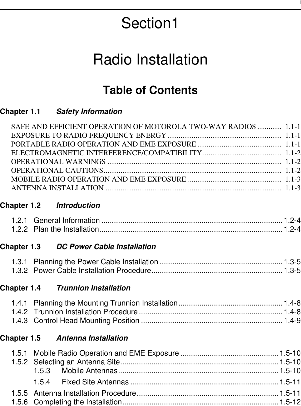
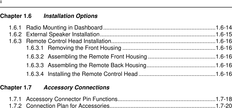
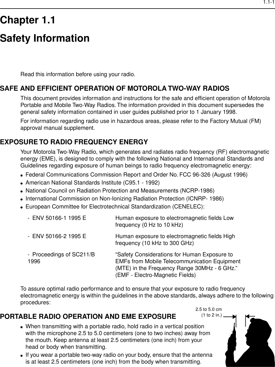
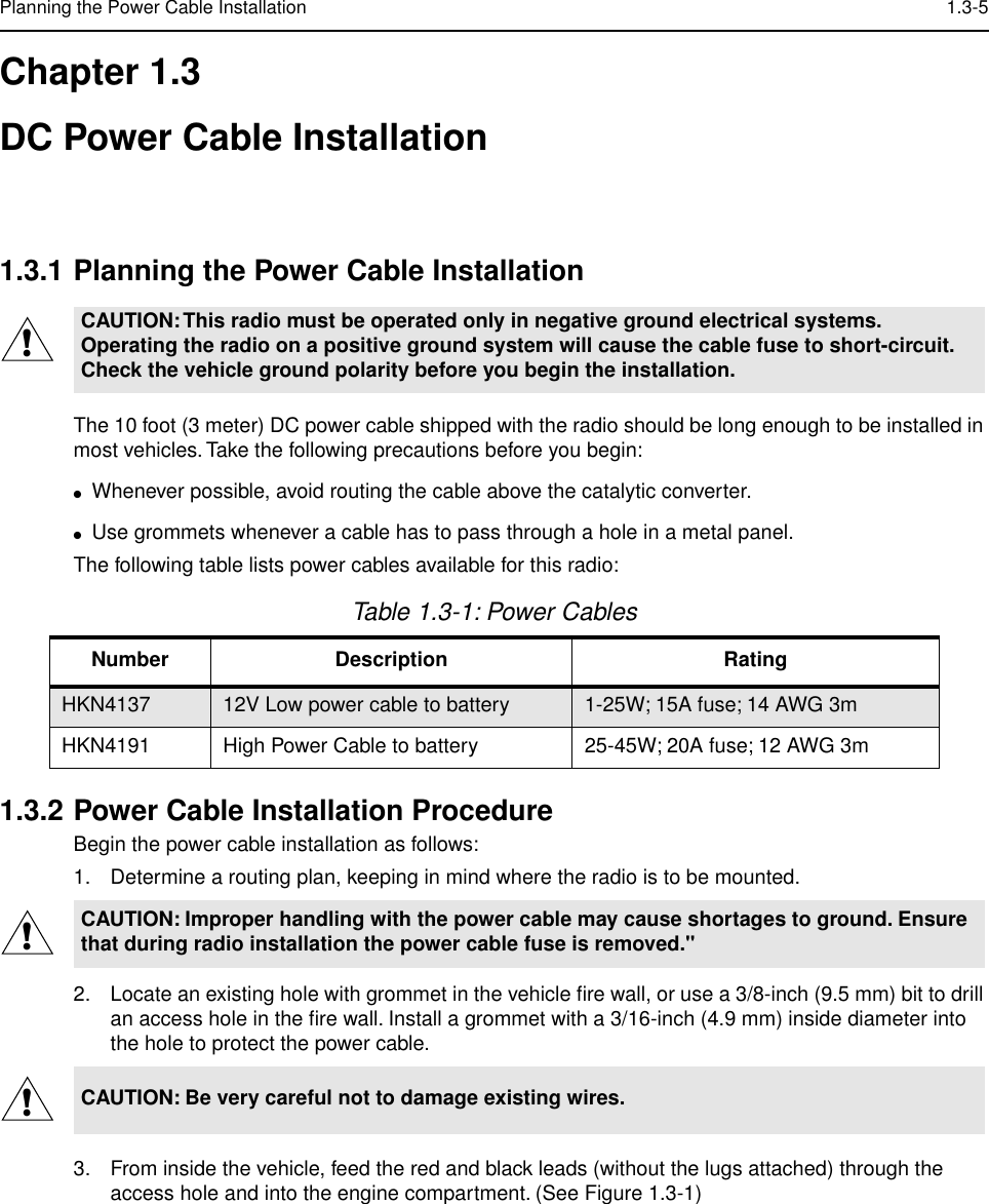
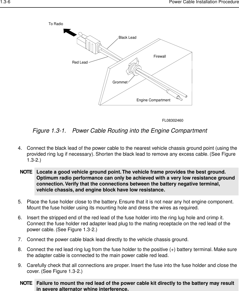
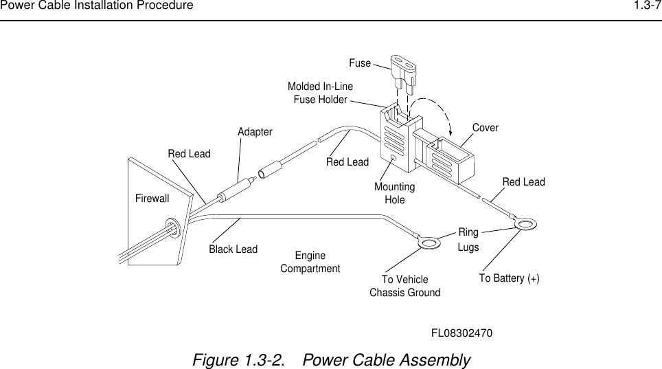
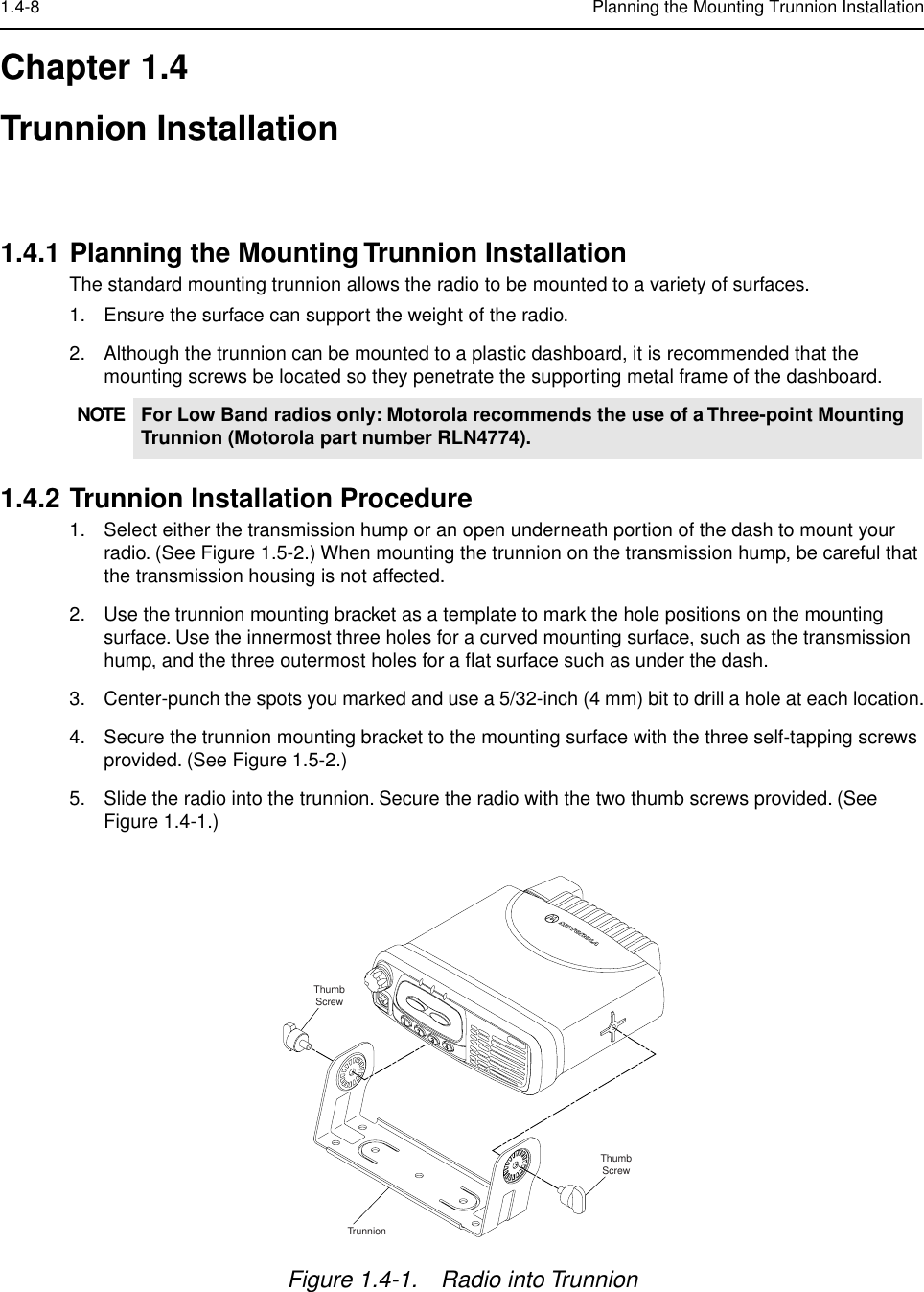
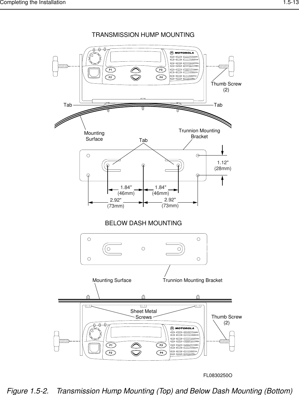
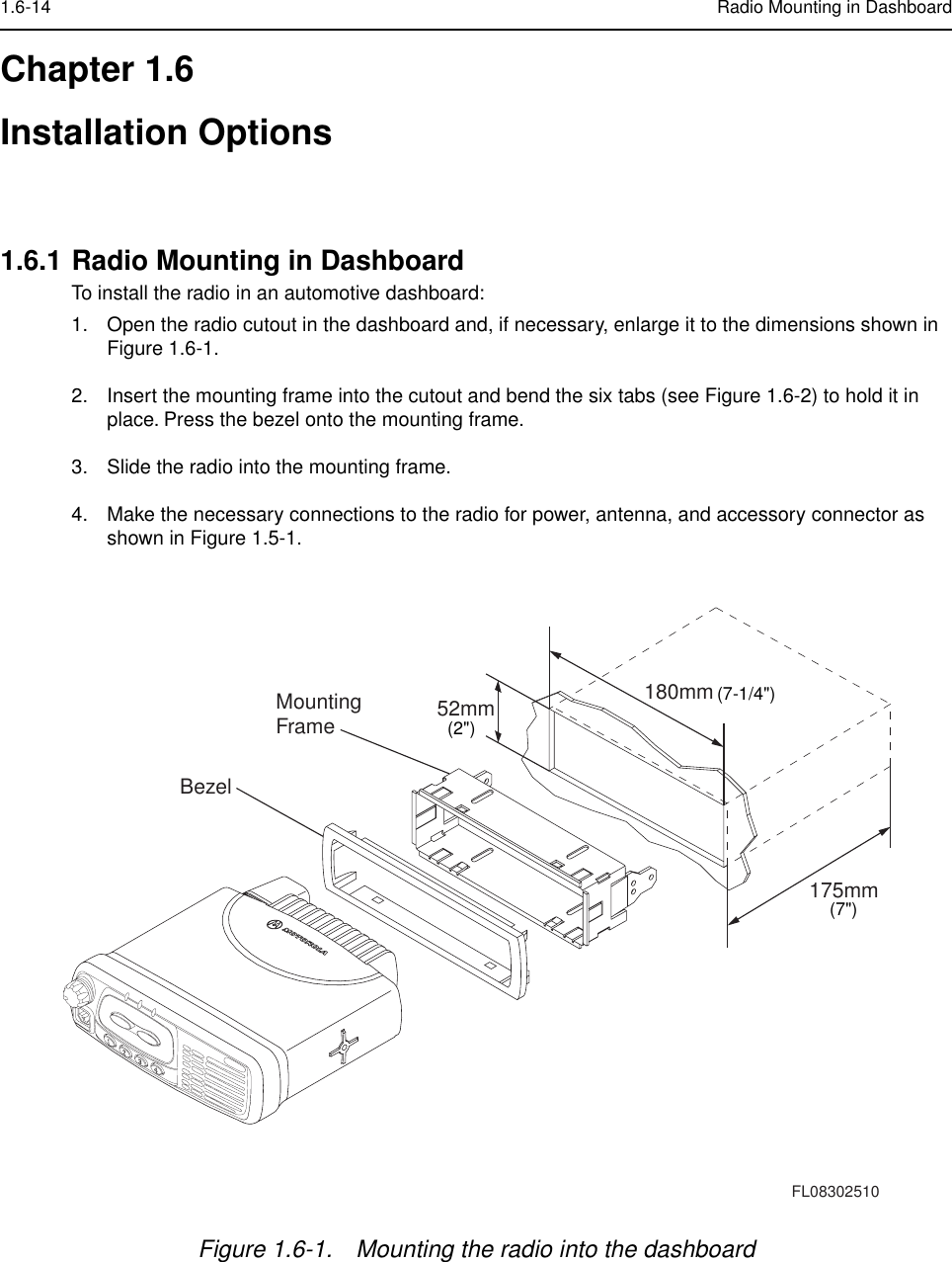
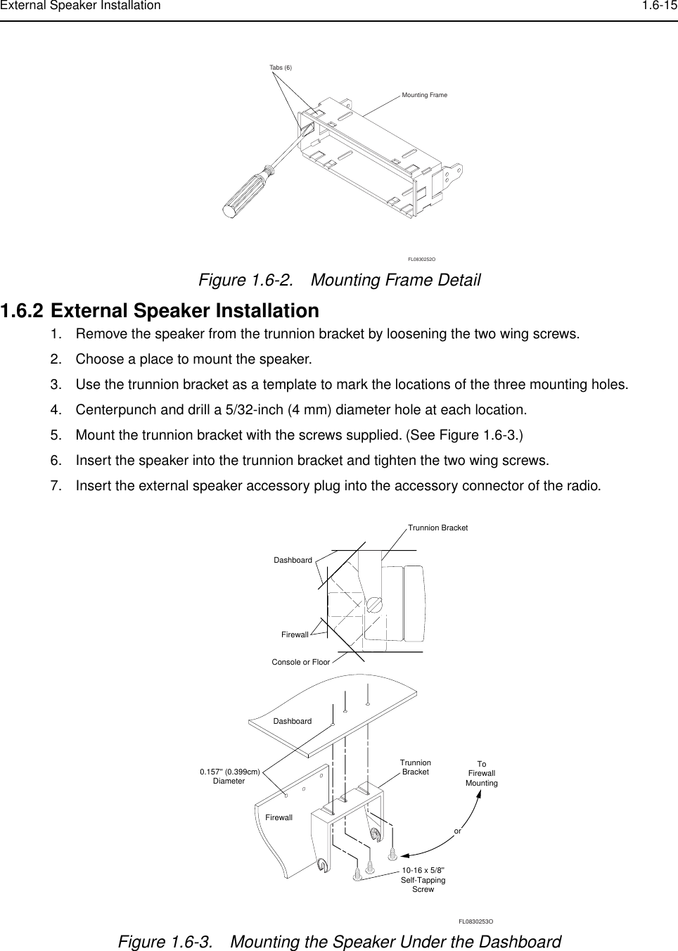
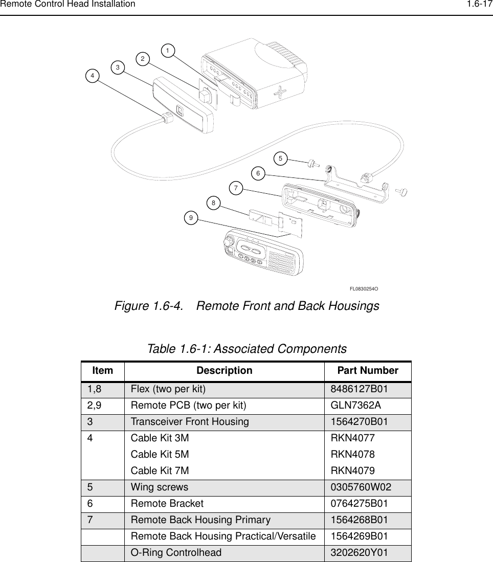
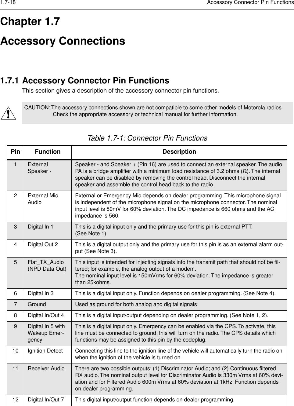
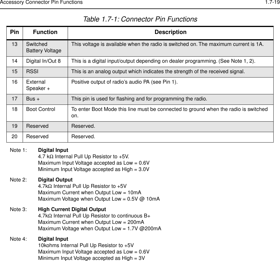
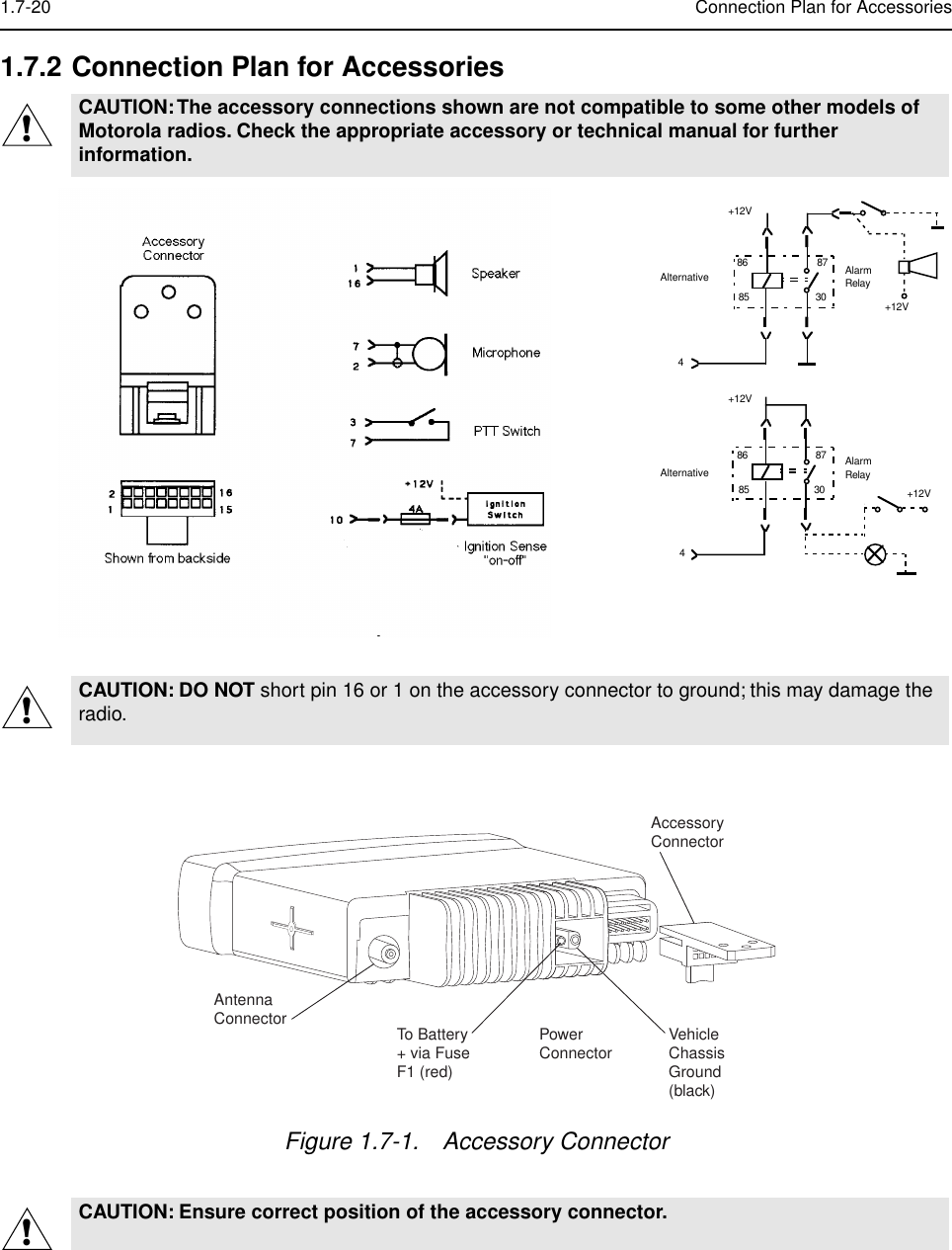
installation manual