Motorola Solutions 92FT1629 Low Band Mobile 2-Way Radio User Manual PM1200
Motorola Solutions, Inc. Low Band Mobile 2-Way Radio PM1200
Ex8 Users Manual
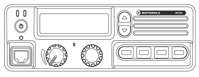
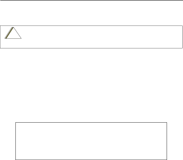
PM1200 Control Head
PM1200.book Page i Thursday, June 21, 2007 3:58 PM

PM1200 Mobile Radio with Control Head i
PM1200 Mobile Radio
with Control Head
User’s Guide
6880309U08-A
*6880309U08*
PM1200.book Page i Thursday, June 21, 2007 3:58 PM
iii
Product Safety and RF Exposure Product Safety and RF
Exposure Compliance
ATTENTION!
This radio is restricted to occupational use only to satisfy FCC RF energy
exposure requirements. Before using this product, read the RF energy
awareness information and operating instructions below.
Product Safety and RF Energy Exposure Booklet
for Mobile Two-Way Radios Installed in Vehicles
or as Fixed Site Control Stations
ATTENTION!
The information provided in this document supersedes the general safety information
contained in user guides published prior to February 2002.
RF Energy Exposure Awareness and Control Information, and
Operational Instructions for FCC Occupational Use
Requirements
NOTICE: This radio is intended for use in occupational/controlled conditions,
where users have full knowledge of their exposure and can exercise
control over their exposure to meet FCC limits. This radio device is NOT
authorized for general population, consumer, or any other use.
This 2-way radio uses electromagnetic energy in the radio frequency (RF) spectrum to
provide communications between two or more users over a distance. It uses radio
frequency (RF) energy or radio waves to send and receive calls. RF energy is one form
of electromagnetic energy. Other forms include, but are not limited to, sunlight and x-
rays. RF energy, however, should not be confused with these other forms of
electromagnetic energy, which when used improperly, can cause biological damage.
Very high levels of x-rays, for example, can damage tissues and genetic material.
Experts in science, engineering, medicine, health, and industry work with organizations
to develop standards for safe exposure to RF energy. These standards provide
recommended levels of RF exposure for both workers and the general public. These
recommended RF exposure levels include substantial margins of protection.
Before using this product, read the operating instructions for safe
usage contained in the Product Safety and RF Exposure booklet
enclosed with your radio.
BEFORE USING THIS RADIO, READ THIS BOOKLET WHICH
CONTAINS IMPORTANT OPERATING INSTRUCTIONS FOR
SAFE USAGE AND RF ENERGY AWARENESS AND CONTROL
INFORMATION FOR COMPLIANCE WITH RF ENERGY
EXPOSURE LIMITS IN APPLICABLE NATIONAL AND
INTERNATIONAL STANDARDS.
!
C
a u t i o
n
PM1200.book Page iii Thursday, June 21, 2007 3:58 PM

PM1200 Mobile Radio with Control Head iv
All Motorola 2-way radios are designed, manufactured, and tested to ensure they meet
government-established RF exposure levels. In addition, manufacturers also
recommend specific operating instructions to users of 2-way radios. These instructions
are important because they inform users about RF energy exposure and provide
simple procedures on how to control it.
Please refer to the following Web sites for more information on what RF energy
exposure is and how to control your exposure to assure compliance with established
RF exposure limits.
http://www.fcc.gov/oet/rfsafety/rf-faqs.html
http://www.osha.gov/SLTC/radiofrequencyradiation/index.html
Federal Communication Commission Regulations
The FCC rules require manufacturers to comply with the FCC RF energy exposure
limits for mobile 2-way radios before they can be marketed in the U.S. When 2-way
radios are used as a consequence of employment, the FCC requires users to be fully
aware of and able to control their exposure to meet occupational requirements.
Exposure awareness can be facilitated by the use of a label directing users to specific
user awareness information. Your Motorola 2-way radio has a RF exposure product
label. Also, your Motorola user manual, or separate safety booklet, includes information
and operating instructions required to control your RF exposure and to satisfy
compliance requirements.
Compliance with RF Exposure Standard
Your Motorola two-way radio is designed and tested to comply with a number of
national and international standards and guidelines (listed below) regarding human
exposure to radio frequency electromagnetic energy. This radio complies with the IEEE
and ICNIRP exposure limits for occupational/controlled RF exposure environment at
duty factors of up to 50% talk-50% listen and is authorized by the FCC for occupational
use. In terms of measuring RF energy for compliance with the FCC exposure
guidelines, your radio antenna radiates measurable RF energy only while it is
transmitting (during talking), not when it is receiving (listening) or in standby mode.
Your Motorola two-way radio complies with the following RF energy exposure
standards and guidelines:
• United States Federal Communications Commission, Code of Federal Regulations;
47CFR part 2 sub-part J
• American National Standards Institute (ANSI) / Institute of Electrical and Electronic
Engineers (IEEE) C95. 1-1992
• Institute of Electrical and Electronic Engineers (IEEE) C95.1-2005 Edition
• International Commission on Non-Ionizing Radiation Protection (ICNIRP) 1998
• Ministry of Health (Canada) Safety Code 6. Limits of Human Exposure to Radio
Frequency Electromagnetic Fields in the Frequency Range from 3 kHz to 300 GHz,
1999
• Australian Communications Authority Radiocommunications (Electromagnetic
Radiation - Human Exposure) Standard, 2003
• ANATEL, Brazil Regulatory Authority, Resolution 256 (April 11, 2001) “additional
requirements for SMR, cellular, and PCS product certification.”
PM1200.book Page iv Thursday, June 21, 2007 3:58 PM

v
RF Exposure Compliance and Control Guidelines and Operating
Instructions
To control exposure to yourself and others and to ensure compliance with the RF
exposure limits, always adhere to the following procedures.
Guidelines:
• User awareness instructions should accompany device when transferred to other
users.
• Do not use this device if the operational requirements described herein are not met.
Instructions:
•Transmit no more than the rated duty factor of 50% of the time. To transmit
(talk), push the Push-To-Talk (PTT) button or, for radios equipped with VOX, speak
into the microphone. The red LED will illuminate when the radio is transmitting. To
receive calls, release the PTT button, or, for radios equipped with VOX, stop talking.
The red LED will extinguish when the radio stops transmitting. Transmitting 50% of
the time, or less, is important because this radio generates measurable RF energy
exposure only when transmitting (in terms of measuring for standards compliance).
•Transmit only when people outside the vehicle are at least the recommended
minimum lateral distance away, as shown in Table 1, from the body of a vehicle
with a properly installed antenna. This separation distance will ensure that there is
sufficient distance from a properly installed (according to installation instructions)
externally-mounted antenna to satisfy the RF exposure requirements in the
standards listed above.
NOTE: Table 1 below lists the recommended lateral distance for people in an
uncontrolled environment from the body of a vehicle with an approved, properly
installed transmitting antenna (i.e., monopoles over a ground plane, or dipoles)
at several different ranges of rated radio power for mobile radios installed in a
vehicle.
• When a mobile radio is used in conjunction with another co-located transmitter such as a
Vehicular Repeater, it is the vehicle operator’s responsibility to take appropriate steps to
keep bystanders at the required separation distance from the vehicle to ensure
compliance with the FCC's RF energy exposure limits for the general population. See the
co-located transmitter’s user manual for more details.
NOTE: If you are not sure of the rated power of your radio, contact your Motorola
representative or dealer and supply the radio model number found on the radio
model label. If you can not determine the rated power out, then assure 5.08-feet
separation from the body of the vehicle. The maximum power shown on the
FCC Grant may be higher than the rated power allowing for production
variation.
Mobile Antenna Installation Guidelines
• These mobile antenna installation guidelines are limited to metal body motor vehicles
or vehicles with appropriate ground planes.
Table 1. Rated Power of Vehicle-Installed Mobile Two-Way Radio and Recommended
Minimum Lateral Distance from Vehicle Body
Mobile Radio Rated
Power (see Note) Minimum Lateral Distance from
Vehicle Body
111 to 125 watts 5.0 feet
PM1200.book Page v Thursday, June 21, 2007 3:58 PM

PM1200 Mobile Radio with Control Head vi
• Antennas should be installed in the center area of the roof or the trunk lid taking into
account exposure conditions of backseat passengers and according to the specific
instructions and restrictions in the Radio Installation Manual along with the
requirements of the antenna supplier.
• Trunk lid installations are limited to vehicles with clearly defined flat trunk lids, and in
some cases, to specific radio models and antennas. See the Radio Installation
Manual for specific information on how and where to install specific types of
approved antennas to facilitate recommended operating distances to all potentially
exposed persons.
•Use only the Motorola-approved, supplied antenna or a Motorola-approved
replacement antenna. Unauthorized antennas, modifications, or attachments could
damage the radio and may result in non-compliance with RF Safety Standards.
Approved Accessories
• This radio has been tested and meets RF Safety Standards when used with the
Motorola accessories supplied or designated for this product. Use of other
accessories may result in non-compliance with RF Safety Standards.
• For a list of Motorola-approved antennas, visit the following Web site, which lists
approved accessories for your radio model:
http://www.motorola.com/cgiss/index.shtml.
Additional Information
For additional information on exposure requirements or other training information, visit
http://www.motorola.com/rfhealth.
Compliance and Control Guidelines and Operating Instructions for
Mobile Two-Way Radios Installed as Fixed Site Control Stations
If mobile radio equipment is installed at a fixed location and operated as a control
station or as a fixed unit, the antenna installation must comply with the following
requirements in order to ensure optimal performance and compliance with the RF
energy exposure limits in the standards and guidelines listed on page iv:
• The antenna should be mounted outside the building on the roof or a tower if at all
possible.
• As with all fixed site antenna installations, it is the responsibility of the licensee to
manage the site in accordance with applicable regulatory requirements and may
require additional compliance actions such as site survey measurements, signage,
and site access restrictions in order to ensure that exposure limits are not exceeded.
• For additional installation information, see the guidelines for minimum separation
distances provided above in the RF Exposure Compliance and Control Guidelines
and Operating Instructions section of this document.
Electromagnetic Interference/Compatibility
NOTE: Nearly every electronic device is susceptible to electromagnetic interference
(EMI) if inadequately shielded, designed, or otherwise configured for
electromagnetic compatibility. It may be necessary to conduct compatibility
testing to determine if any electronic equipment used in or around vehicles or
near fixed site antenna is sensitive to external RF energy or if any procedures
need to be followed to eliminate or mitigate the potential for interaction between
the radio transmitter and the equipment or device.
PM1200.book Page vi Thursday, June 21, 2007 3:58 PM

vii
Facilities
To avoid electromagnetic interference and/or compatibility conflicts, turn off your radio
in any facility where posted notices instruct you to do so. Hospitals or health care
facilities may be using equipment that is sensitive to external RF energy.
Vehicles
To avoid possible interaction between the radio transmitter and any vehicle electronic
control modules, such as ABS, engine, or transmission controls, the radio should be
installed only by an experienced installer and the following precautions should be used
when installing the radio:
1. Refer to the manufacturer’s instructions or other technical bulletins for
recommendations on radio installation.
2. Before installing the radio, determine the location of the electronic control modules
and their harnesses in the vehicle.
3. Route all radio wiring, including the antenna transmission line, as far away as
possible from the electronic control units and associated wiring.
Driver Safety
Check the laws and regulations on the use of radios in the area where you drive.
Always obey them.
When using your radio while driving, please:
• Give full attention to driving and to the road.
• Pull off the road and park before making or answering a call if driving conditions so
require.
Operational Warnings
For Vehicles with an Air Bag
Do not mount or place a mobile radio in the area over an air bag
or in the air bag deployment area. Air bags inflate with great force.
If a radio is placed in the air bag deployment area and the air bag
inflates, the radio may be propelled with great force and cause
serious injury to occupants of the vehicle.
Potentially Explosive Atmospheres
Turn off your radio prior to entering any area with a potentially
explosive atmosphere. Sparks in a potentially explosive
atmosphere can cause an explosion or fire resulting in bodily
injury or even death.
The areas with potentially explosive atmospheres include fueling
areas such as below decks on boats, fuel or chemical transfer or
storage facilities, and areas where the air contains chemicals or
particles such as grain, dust or metal powders. Areas with
potentially explosive atmospheres are often, but not always,
posted.
!
C
a u t i o
n
PM1200.book Page vii Thursday, June 21, 2007 3:58 PM

PM1200 Mobile Radio with Control Head viii
Computer Software Copyrights
The Motorola products described in this manual may include copyrighted Motorola
computer programs stored in semiconductor memories or other media. Laws in the
United States and other countries preserve for Motorola certain exclusive rights for
copyrighted computer programs, including, but not limited to, the exclusive right to copy
or reproduce in any form the copyrighted computer program. Accordingly, any
copyrighted Motorola computer programs contained in the Motorola products described
in this manual may not be copied, reproduced, modified, reverse-engineered, or
distributed in any manner without the express written permission of Motorola.
Furthermore, the purchase of Motorola products shall not be deemed to grant either
directly or by implication, estoppel, or otherwise, any license under the copyrights,
patents or patent applications of Motorola, except for the normal non-exclusive license
to use that arises by operation of law in the sale of a product.
Documentation Copyrights
No duplication or distribution of this document or any portion thereof shall take place
without the express written permission of Motorola. No part of this manual may be
reproduced, distributed, or transmitted in any form or by any means, electronic or
mechanical, for any purpose without the express written permission of Motorola.
Disclaimer
The information in this document is carefully examined, and is believed to be entirely
reliable. However, no responsibility is assumed for inaccuracies. Furthermore, Motorola
reserves the right to make changes to any products herein to improve readability,
function, or design. Motorola does not assume any liability arising out of the
applications or use of any product or circuit described herein; nor does it cover any
license under its patent rights, nor the rights of others.
MOTOROLA, the Stylized M Logo, and FLASHport are registered in the U.S. Patent &
Trademark Office. All other product or service names are the property of their
respective owners.
© Motorola, Inc. 2007. Printed in the USA.
Blasting Caps and Blasting Areas
To avoid possible interference with blasting operations, turn off
your radio when you are near electrical blasting caps, in a blasting
area, or in areas posted: “Turn off two-way radio.” Obey all signs
and instructions.
For radios installed in vehicles fueled by liquefied petroleum gas,
refer to the (U.S.) National Fire Protection Association standard,
NFPA 58, for storage, handling, and/or container information. For a
copy of the LP-gas standard, NFPA 58, contact the National Fire
Protection Association, One Battery Park, Quincy, MA.
!
W
A R N I N
G
!
PM1200.book Page viii Thursday, June 21, 2007 3:58 PM

ix
Notes
PM1200.book Page ix Thursday, June 21, 2007 3:58 PM

PM1200 Mobile Radio with Control Head x
Contents
PM1200 Control Head . . . . . . . . . . . . . . . . . . . . . . . . . . i
Declaration of Conformity .................................................................. ii
Computer Software Copyrights .......................................................viii
Documentation Copyrights ..............................................................viii
Disclaimer .......................................................................................viii
PM1200 Operating Manual ............................................................... 1
Controls & Connectors ...................................................................... 3
Front Panel ............................................................................... 3
REAR (Heatsink) ........................................................................ 6
Basic Operation of the Transceiver ................................................... 7
Switching Power ON/OFF .......................................................... 7
Setting the Volume ..................................................................... 7
Transmitting ................................................................................ 7
Selecting Groups and Channels ................................................. 8
Automatic Time-Out Timer ......................................................... 8
Radio Firmware Features ................................................................. 9
Accessories . . . . . . . . . . . . . . . . . . . . . . . . . . . . . . . . . 29
Speakers ......................................................................................... 29
Microphones ................................................................................... 29
Switches .......................................................................................... 29
Miscellaneous ................................................................................. 30
Antenna ........................................................................................... 30
Signaling Boards ............................................................................. 31
Cables ............................................................................................. 31
Glossary. . . . . . . . . . . . . . . . . . . . . . . . . . . . . . . . . . . . 33
Commercial Warranty and Service . . . . . . . . . . . . . . 35
Limited Warranty ............................................................................. 35
Service ............................................................................................ 39
PM1200.book Page x Thursday, June 21, 2007 3:58 PM

xi
Notes
PM1200.book Page xi Thursday, June 21, 2007 3:58 PM
PM1200 Mobile Radio with Control Head 1
PM1200 Operating Manual
PM1200 Operating Manual
PM1200 is a full featured FM transceiver, designed for flexible mobile
and base station business communications in the VHF Low-Band
frequency range (120/50 Watts: programmable). Each model is
designed for reliable business communications in a wide variety of
applications, with a wide range of operating capability provided by its
leading-edge design.
The 250-channel memories can each be programmed with a
8-character channel name. Important channel frequency data is
stored in EEPROM and flash memory on the CPU, and is easily
programmable by dealers using a personal computer and the CPS
Telco programming cable(AARKN4081B).
The following pages list the advanced features of PM1200
transceiver. You may wish to consult your Network Administrator
regarding details of the configuration of this equipment for use in your
application.
PM1200.book Page 1 Thursday, June 21, 2007 3:58 PM

2
PM1200 Operating Manual
For North American Users Regarding 406 MHz Guard Band
The U.S. Coast Guard and National Oceanographic and
Atmospheric Administration have requested the cooperation of
the U.S. Federal Communications Commission in preserving the
integrity of the protected frequency range 406.0 to 406.1 MHz,
which is reserved for use by distress beacons. Do not attempt to
program this apparatus, under any circumstances, for operation
in the frequency range 406.0 - 406.1 MHz if the apparatus is to be
used in or near North America.
PM1200.book Page 2 Thursday, June 21, 2007 3:58 PM
PM1200 Mobile Radio with Control Head 3
Controls & Connectors
Controls & Connectors
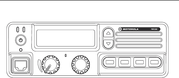
Front Panel
1. Power Button
Press the button to turn the transceiver ON and OFF.
2. TX Indicator
The LED lights up solid red when the radio is transmitting.
3. Busy Indicator
The LED lights up solid green when the channel is busy.
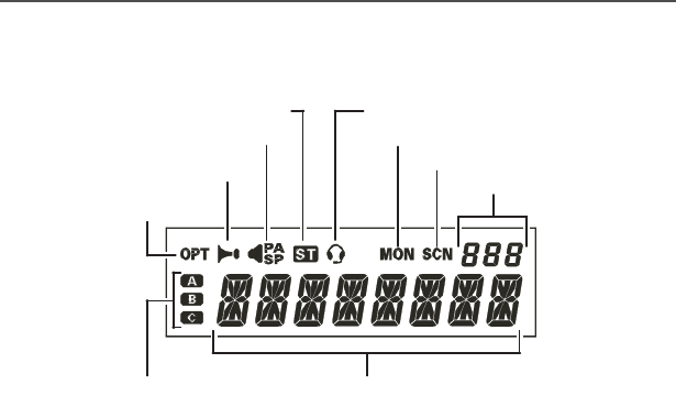
4. Liquid Crystal Display
The display includes an 8-character alpha-numeric section showing
channel and group names, status and identity information, and error
messages. Additional indicators on the display show priority channel
assignments and scan include / exclude selection.
234512
1
6
7 8 910 11
PM1200.book Page 3 Thursday, June 21, 2007 3:58 PM
4
Controls & Connectors
5. Channel Group Keys
Press up and down keys to change current group (and to display
group number or name). Hold the button for more than 1/2 second to
repeat the function.
6. DSC Indicator
When DSC feature is enabled, the DSC indicator blinks orange when
the position of volume selector knob and/or channel selector knob are
different than the pre-set position. The DSC indicator stops blinking
when you successfully set the desired position.
7. Telco Connector for Microphone
Connect the microphone connector to this jack.
8. Volume Selector Knob
Used to set the volume of the receiver.
This channel on “S
ELECTABLE
T
ONE
” List
This channel on “P
UBLIC
A
DDRESS
” or
“S
PEAKER
” List
This channel on “H
ORN
A
LERT
” List
This channel on
“O
PTION
” List
This channel on “I
NTERCOM
” List
Receiver Monitor
This channel on “S
CAN
” List
Channel Group Number
This channel on “AUX A/B/C” List
8 Character Alpha-numeric Display
PM1200.book Page 4 Thursday, June 21, 2007 3:58 PM

PM1200 Mobile Radio with Control Head 5
Controls & Connectors
9. Emergency Microphone
Emergency microphone is enabled when the Emergency feature is
activated.
10. Channel Selector Knob
Used to select the operating channel.
11. Programmable Function Buttons (PF button)
These buttons can be programmed to special functions, such as
Toggle High/Low Power Selection, Monitor, Dimmer, Talkaround,
Toggle Scan On/Off, Dual Watch, Squelch Level, Emergency,
Speaker Change, Public Address, Revert Memory Channel 1, Revert
Memory Channel 2, Selectable Tone, Alpha Numeric, Intercom, Horn
Alert, Home Channel, Noise Blanker, Scan List Select, Selected
Channel Priority, Audio Volume Attenuation, Scan Select, Group
Scan Select and Unassigned function, as determined by your network
requirements and programmed by your MOTOROLA dealer.
12. Internal Speaker
The internal speaker allows audio to be heard when receiving a call.
Internal speaker is enabled unless the external speaker is connected.
PM1200.book Page 5 Thursday, June 21, 2007 3:58 PM
6
Controls & Connectors
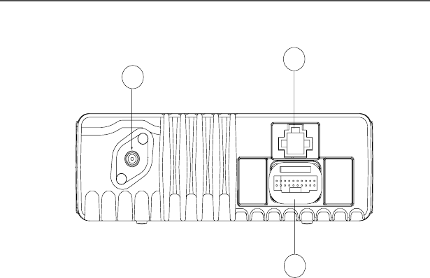
REAR (Heatsink)
1. Antenna Socket
The 50-ohm coaxial feedline to the antenna must be connected here,
using a Mini-UHF connector.
2. 13.4-V DC Power Connector
The supplied DC power cable must be connected to this 4-pin
connector. Use only the supplied fused cable (extended if necessary)
for power connection.
3. 20-Pin Accessory Connector
Connect the accessory connector to this 20-Pin jack. This connector
can be used to connect the external speaker, vehicular hands-free
and other supported accessories.
1
2
3
PM1200.book Page 6 Thursday, June 21, 2007 3:58 PM

PM1200 Mobile Radio with Control Head 7
Basic Operation of the Transceiver
Basic Operation of the Transceiver
Important! - Before turning on the radio for the first time, please
ensure that the power connections are connected properly and that
an antenna is connected to the antenna jack.
Switching Power ON/OFF
Push the power switch to turn on the radio. The display will illuminate.
The radio will start up on the last channel used prior to shut-down
during the previous operating session.
Turn the channel selector knob to choose the desired operating
channel. A channel name will appear on the display. If you want to
select the operating channel from a different group, press the or
button to select the different group that you want before selecting
the operating channel.
Setting the Volume
Turn the volume selector knob clockwise to increase the volume, and
counterclockwise to decrease it. If no signal is present, press and
hold the MON button for more than 1/2 second. Background noise will
now be heard, and you may set the volume selector knob to the
desired audio level. Press and hold the MON button more than 1/2
second to decrease the noise and resume normal (quiet) monitoring.
Transmitting
To transmit, wait until the "BUSY" indicator is off (the channel is not in
use), and press the PTT (Push-To-Talk) button on the side of the
microphone (the "TX" indicator will appear or the "TX" indicator will
glow red). While holding in the PTT button, speak into the microphone
clearly, and then release the PTT button to receive.
PM1200.book Page 7 Thursday, June 21, 2007 3:58 PM

8
Basic Operation of the Transceiver
Selecting Groups and Channels
Press the or button (repeatedly, if necessary) to select different
group of channels.
Turn the channel selector knob to select different channel within the
current group.
Automatic Time-Out Timer
If the selected channel has been programmed for automatic time-out,
you must limit the length of each transmission. During transmission, a
beep will sound ten seconds before time-out. Another beep will sound
just before the deadline. The "TX" indicator will disappear and
transmission will cease soon thereafter. To resume transmission,
release the PTT button and wait for the "penalty timer" to expire (if
you press the PTT button before the timer expires, the timer restarts,
and you will have to wait another "penalty" period)
PM1200.book Page 8 Thursday, June 21, 2007 3:58 PM

PM1200 Mobile Radio with Control Head 9
Radio Firmware Features
Radio Firmware Features
1.0 Number of Channels/Groups
PM1200 HP mobile is capable of supporting up to 250-channels. The
250-channels memories can each be programmed with 8-characters
channel name. The 250-channel capacity may be partitioned into as
many as 250 memory groups, where the total number of channels
should be 250 channels. The groups programmed in the
programming data can be selected via the /Button.
2.0 Frequency Band
The frequency range for PM1200 HP mobile is as follow:
Low Band (A) 29.7 - 37 MHz
Low Band (B) 37 - 50 MHz
3.0 Power Level
PM1200 HP mobile has two power levels; High Power (Hi) and Low
Power(Low). The power levels can be set via the CPS and must be
set for each channel. The Hi/Low power can also be toggle using one
of the four PF buttons on the front of the radio. Low power level is set
to 50W and High power level is set to 120W. Default factory setting is
120W.
PM1200.book Page 9 Thursday, June 21, 2007 3:58 PM

10
Radio Firmware Features
4.0 LED Indications
The following table describes the LED indications of the radio:
Table 1: LED Indications
Radio Status Tx LED
color
Busy
LED
color
DSC LED
color
Transmitting Solid Red
Receiving signal with
TPL/DPL enabled
Solid
Green
Receiving signal with
TPL/DPL disabled
Solid
Green
Scan landed on Rx
Channel with TPL/DPL
enabled
Solid
Green
Scan landed on Rx
Channel with TPL/DPL
disabled
Solid
Green
Incorrect setting of the
volume selector knob &
channel selector knob
Blinking
Orange
PM1200.book Page 10 Thursday, June 21, 2007 3:58 PM

PM1200 Mobile Radio with Control Head 11
Radio Firmware Features
5.0 Self Test
When the radio is on, it performs a routine check to initialize and to
check for any possible hardware error before actual usage.
An error code appears when there is an error during the self test.
Description of the error codes is as follow:
Error1: General communication data error.
Most likely caused by one of the listed conditions in the Programming
Problems section.
Error2: Incompatible administrative data.
Overhead programming data (which is not displayed by the
programming software) is incompatible with the radio. This also
occurs occasionally during radio-to-radio cloning.
6.0 Radio Configuration
The features described below are set as radio wide setting.
6.1 Time-Out Timer
Time-Out Timer (TOT) is the maximum amount of communication
time allowed per transmission, while operating the radio. Once this
time expires, the transmission is automatically terminated. TOT is set
through the CPS.
The transmit time-out timer can be set between 0.5 minute to 7.5
minute in increment of 0.5 minute or "unlimited". When a call is
initiated, the radio starts the transmit time-out timer. During
transmission, the radio generates a time-out timer warning tone ten
seconds before time-out, indicating that the radio is about to stop
transmitting. Another beep will sound just before the deadline. To
resume transmission, release the PTT button and wait for the penalty
timer to expire. If you press the PTT button before penalty timer
expires, the timer will restart, and you will have to wait another
"penalty" period.
PM1200.book Page 11 Thursday, June 21, 2007 3:58 PM

12
Radio Firmware Features
6.2 Default Status Check (DSC)
You can pre-set the volume selector knob to a desired volume level (0
to 10). You can also pre-set the channel selector knob to a desired
channel via the CPS. When DSC feature is enabled, the DSC
indicator (located beneath the power button) blinks orange when the
position of volume selector knob and/or channel selector knob are
different than the pre-set position (desired position). The DSC
indicator will stop blinking when you successfully sets this to the
programmed position.
7.0 Scan Feature
Scan feature allows you to listen for activity on more than one
conventional channel. The lists of channels that the radio scans and
other parameters associated with scan are specified by a Scan List.
When you press the ‘Scan’ PF button, the radio rapidly moves
through the members of the Scan List looking for activity that would
normally cause the speaker to unmute. The radio unmutes when
such activity are detected. When both Tx and Rx activity has ceased
for the time, the radio will return to the active scan state.
The scan mode can be stop by pressing the assigned ‘Scan’ PF
button again if the Group Scan feature is disabled.
7.1 Dual Watch
This feature is similar to the Scan feature, but Dual Watch only
monitors the current Operating Channel and the Priority Channel. The
radio will scan the two channels when you press the assigned ‘Dual
Watch’ PF button. It pauses each time it finds a channel on which
someone is speaking. You can stop the Dual Watch feature by
pressing the assigned PF button again. The operation will revert to
the channel to which the channel selector knob is set.
PM1200.book Page 12 Thursday, June 21, 2007 3:58 PM

PM1200 Mobile Radio with Control Head 13
Radio Firmware Features
7.2 Talkback Scan
Talkback Scan allows you to transmit during scanning pause. This
feature can be enabled and disabled via the CPS. If talkback is
enabled and the radio is in scanning pause on the landed channel,
press the PTT button and the radio will transmit on landed channel. If
the talkback is disabled, then the radio should not be able to transmit
on the landed channel when the PTT button is pressed. Instead it will
transmit on the selected channel.
8.0 Conventional Personality
This section decribes the individual function of the conventional
personality. The features described below takes effect on a per
channel basis. It will only affect the particular channel parameter
settings and allows each channel to have their own configuration.
These individual channel personalities can also be grouped together.
8.1 Busy Channel Lockout (BCLO)
Busy Channel Lockout (BCLO) is the channel lockout rules while
operating on the current channel.
When BCLO is disabled via the CPS, you can transmit even if the
radio is actively receiving. Press the PTT button to unmute the
speaker.
When BCLO (on carrier) is enabled via the CPS, you are not allowed
to transmit when the radio is actively receiving. Press the PTT button
to unmute the speaker.
BCLO (on wrong PL) will not allow transmission when the radio is
actively receiving (carrier is present) or when an invalid tone is
present.
PM1200.book Page 13 Thursday, June 21, 2007 3:58 PM

14
Radio Firmware Features
8.2 Scan List
The list of channels that the radio scans and other parameters
associated with scan members are specified in scan list. Each scan
list can be configured in the CPS. Scan List has a collection of groups
and each group consists of User Scan Lists, Dealer Scan List, Priority
Scan Channel and Multiple Group Selection.
9.0 Standard Conventional Operation
Conventional operations of the radio are Carrier Squelch operation,
TPL, DPL and Invert DPL
Different groups of radio users share the same frequency or channel
(community repeater). Without the use of Private Line (PL) tones/
codes, each individual group would constantly listen to the
transmissions of all groups; this is known as Carrier Squelch
operation. Private Line operation is done by outfitting members of
each group with radios containing a unique PL tone/code. Their
radios will then only unmute to transmissions made by other
members of their group. If radios are set to only unmute when a
transmission includes their own PL tone/code, then they are not
disturbed by conversations of other groups. The sub-audible code
that is added to the voice unmutes only those radios with an identical
PL tone/code. There are two forms of PL available: Tone Private Line
(TPL) and Digital Private Line (DPL).
TPL signaling consists of a sub-audible tone that is continuously
modulated onto the carrier. The receiving radio will continuously
monitor the carrier, and if the correct sub-audible tone is present, the
speaker will unmute to the recovered audio. TPL tones are summed
together with the voice information during encoding. There are 39
standard sub-audible Telecommunications Industry Associate (TIA)/
Electronic Industry Association (EIA) tones between 67.0 Hz and
250.3 Hz, inclusively. The radio will follow the standard for sub-
audible Continuous Tone Controlled Squelch System (CTCSS) that is
covered in TIA/EIA-603.
PM1200.book Page 14 Thursday, June 21, 2007 3:58 PM

PM1200 Mobile Radio with Control Head 15
Radio Firmware Features
DPL signaling consists of a continuous sub-audible digital signal
transmitted simultaneously with a voice message. DPL is similar to
TPL except that a digital pattern is transmitted rather than a tone. The
radio will follow the standard for sub-audible Continuous Digital
Controlled Squelch System (CDCSS) that is covered in TIA/EIA-603.
Carrier Squelch operation does not require that a sub-audible signal
be decoded in order to unmute the radio's speaker. Likewise, it does
not produce a sub-audible signal during transmission.
9.1 Carrier Squelch Operation (CSQ)
The radio unmutes when the carrier energy exceeds the radio-
designated carrier energy threshold.
When the energy is below the Squelch Threshold, carrier squelch
detection is not achieved and radio will remain mute.
If a conventional personality is configured via the CPS to transmit
CSQ only, no PL tones/codes will be transmitted.
If a conventional personality is configured via the CPS to receive
CSQ, no PL tones/codes will be checked. The radio will unmute upon
detection of carrier squelch.
9.2 PL Operation
PL is a Motorola term for CTCSS. PL is a sub-audible tone/code used
to create unique/private communication groups. There are two types
of PL, which in generic terms known as Tone Private Line (TPL) and
Digital Private Line (DPL).
9.2.1 Tone Private Line (TPL)
You can select TPL from the CPS for individual personality. Each
personality have different Squelch type for transmit and receive.
PM1200.book Page 15 Thursday, June 21, 2007 3:58 PM

16
Radio Firmware Features
9.2.1.1 TPL Encode
Conventional channels in the radio with activated Tone Private Line
settings transmit with the selected Tone Private Line code (transmit
TPL).
If TPL is selected, the radio will transmit the TPL code on the selected
conventional personality.
The TPL code determines which code the conventional personality
will transmit.
9.2.1.2 TPL Decode
Receive TPL is used upon detection of a sub-audible tone that is
used in the unmuting rules of the radio. When the radio decodes the
correct TPL sub-audible tone that is being continuously modulated
onto the carrier, the radio uses this information in determining if the
speaker should be unmuted.
The Rx TPL code determines which code the conventional
personality will attempt to decode & unmute the radio.
9.2.2 Digital Private Line (DPL)
DPL is a Motorola term for CDCSS. DPL is a digital format
transmitted along with the carrier. DPL gives more use and privacy on
a frequency.
DPL is selectable from the CPS for individual personality. Each
personality can have different Squelch type for transmit and receive.
9.2.2.1 DPL Encode
Transmit DPL is the modulation of a sub-audible code on a carrier
frequency. The sub-audible code is summed with microphone audio
prior to modulation.
If DPL is selected, the radio will transmit DPL code on the selected
conventional personality.
The DPL code determines which code the conventional personality
will transmit.
PM1200.book Page 16 Thursday, June 21, 2007 3:58 PM

PM1200 Mobile Radio with Control Head 17
Radio Firmware Features
9.2.2.2 DPL Decode
Receive DPL is used in detection of a sub-audible code that is used in
the unmuting rules of the radio.
If DPL is selected, the radio will receive digital private line code on the
selected conventional personality. The DPL code determines which
code the conventional personality will attempt to decode.
9.2.3 Inverted DPL
Inverted DPL inverts Digital Private Line (DPL) signals when they are
received by the radio. Inverted coding allows more traffic/usage on
frequencies.
If DPL Invert is enabled on the transmit radio but not on the receive
radio, then the receive radio will not un-mute.
If DPL Invert is enabled on the receive radio but not on the transmit
radio, then the receive radio will not un-mute.
If DPL Invert is enabled on both the receive radio and the transmit
radio, then the receive radio will un-mute.
The encode and decode operation of this Inverted DPL should be
similar to DPL except all the bits in the DPL code are inverted in the
DPL operating process.
9.3 TPL Reverse Burst
This feature is used to transmit a Tone Private Line (TPL) code at the
end of a transmission - once the PTT button is released, and while
operating on the current Conventional Personality. This sub-audible
tone causes the receiving radio to mute its speaker before loss of a
carrier is detected. Muting the speaker eliminates unwanted noise
(squelch tail) during loss of carrier detection.
If the TPL Reverse Burst is programmed to standard or non-standard
via the CPS, a Tone Private Line (TPL) shut-off code will be
transmitted at the end of a transmission once the PTT button is
released, on the current Conventional Personality.
PM1200.book Page 17 Thursday, June 21, 2007 3:58 PM

18
Radio Firmware Features
The receiving radio will mute its speaker before loss of a carrier is
detected, upon receiving the TPL reverse burst.
If the TPL Reverse Burst is programmed to None (disabled) via the
CPS, then the TPL reverse burst will not be transmitted at the end,
upon the PTT button release. If the TPL shut-off code is not
transmitted, then the receiving radio will not mute its speaker before
loss of a carrier is detected, unwanted noise (squelch tail) during loss
of carrier detection will be heard.
Table 2 shows the result of squelch tail elimination on the receiving
radio based on the TPL reverse burst setting on transmit and receive
radio.
When Reverse Burst is enabled in the CPS, the TPL Reverse Burst
that is transmitted at the end of the transmission changes the phase
prior to the removal of the carrier to eliminate the squelch tail.
There are 2 formats in use:
- Advances the phase of the tone forward 240 degree
- Advances the phase of the tone forward 180 degree
This setting is programmable in the CPS.
Table 2: Squelch Tail Elimination Results
TPL Tx Reverse Burst Setting Squelch Tail
Elimination
TPL Tx Reverse Burst
on Transmitting Radio
TPL Tx Reverse Burst
on Receiving Radio
Standard Yes
Non-Standard Non-Standard° Yes
Standard No
PM1200.book Page 18 Thursday, June 21, 2007 3:58 PM

PM1200 Mobile Radio with Control Head 19
Radio Firmware Features
10.0 Programmable Function Button
There are four Programmable Function (PF) buttons available. Each
button has two assigned features when the radio is turned on. One
feature is for short press and the other feature is long press.
The features that can be assigned to the PF buttons are:
1.Toggle High/Low Power
2.Monitor
3.Toggle Scan On/Off
4.Dual Watch
5.Talkaround
6.Squelch Level
7.Dimmer
8.Emergency
9.Speaker Change
10.Public Address
11.Revert Memory Channel 1
12.Revert Memory Channel 2
13.Selectable Tone
14.Alpha Numeric
15.Intercom
16.Horn Alert
17.Home Channel
18.Unassigned
19.Noise Blanker - To reduce the car noise
20. Scan List Select
21. Selected Channel Priority
PM1200.book Page 19 Thursday, June 21, 2007 3:58 PM

20
Radio Firmware Features
22. Audio Volume Attenuation
23. Scan Select
24. Group Scan Select
10.1 Toggle High/Low Power
Refer to “Power Level” on page 9.
10.2 Monitor
Monitor feature allows you to listen to current channels of
Conventional dispatch type. Monitor mode places receiver in Carrier
Squelch, overriding receive PL (or CTCSS) signaling. This is a press
and hold feature, which is assigned to a PF Button. The "MON" icon
appears on the LCD when you press the assigned ‘Monitor’ PF
button.
The ‘Monitor’ PF Button automatically sets the short press as quiet
monitoring and the long press as noise monitoring.
Both presses will override PL or Open, depending on setting.
10.3 Toggle Scan On/Off
The assigned button toggles between Scan On and Scan Off when
you press the assigned ‘Toggle’ PF button. The radio will sound and
“SCAN” is displayed on LCD. Press the assigned ‘Toggle’ PF Button
again to enter Group Scan. “G SCAN” will be displayed on the LCD,
provided the radio is in the group which has been selected as Group
Scan member and there are more than two group scan members
programmed in this radio.
PM1200.book Page 20 Thursday, June 21, 2007 3:58 PM

PM1200 Mobile Radio with Control Head 21
Radio Firmware Features
10.4 Dual Watch
This feature is similar to the Scan feature, except that only two
channels are monitored: the current operating channel and the
Priority channel. The radio will search the two channels when you
press the assigned ‘Dual Watch’ PF button. It will pause each time it
finds a channel on which someone is speaking. Dual Watch feature
can be stopped by pressing the assigned ‘Dual Watch’ PF button
again. The operation will revert to the channel to which the channel
selector knob is set.
10.5 Talkaround
You can assign any PF button to Repeater/Talkaround feature via
programming data. The PF button allows you to toggle between
Repeater mode operation and Talkaround mode operation.
The Repeater/Talkaround feature allows you to change the
operational mode from Repeater, which requires the radio to transmit
on the receive frequency of its associated repeater and receive on the
Repeater's transmit frequency, to Talkaround mode operation which
allows a radio to bypass the repeater and talk directly to another radio
by transmitting on the radio's programmed receive frequency.
This features has no effect on simplex channels. After pressing the
button, "-TAKARD-" is displayed on the LCD.
Talkaround must follow decode data setting.
10.6 Squelch Level
When the assigned ‘SQL’ PF button is pressed, a tone sounds and
SQL appears on the display with the current Squelch Level. You can
then select the desired level by rotating the channel selector knob.
After the selection, press the assigned PF button. A tone sounds and
the display returns to the normal channel.
PM1200.book Page 21 Thursday, June 21, 2007 3:58 PM

22
Radio Firmware Features
10.7 Dimmer
The assigned PF Button adjusts the brightness of the display and key
backlight through three levels of brightness and the fourth level
completely turns off the backlight.
10.8 Emergency
When the assigned ‘Emergency’ PF Button is pressed, an
Emergency call will be initiated (MDC-1200 requires ANI board). If the
Emergency LCD and Emergency LED are disabled in the CPS, the
transmitting radio produces no audio or visual indications when an
Emergency call is made. If the Emergency LCD is enabled in the
CPS, the LCD backlight illuminates when the Emergency call is
initiated. If the Emergency LED is enabled in the CPS, the Tx LED will
change to solid red when an Emergency call is initiated. To end an
Emergency call, either press and hold EMG button during receive
condition, or turn off the transceiver.
10.9 Speaker Change
The assigned ‘Speaker Change’ PF button allows you to select
between "Front Panel", "Front Panel & Body", or "Body" speakers.
When "Body" is selected, a tone sounds and the speaker icon
appears on the display. This function can be used while receiving a
call.
10.10 Public Address
The assigned ‘Public Address’ PF button allows you to toggle the PA
amplifier ON and OFF. When this feature is ON, a tone sounds and
the PA icon appears on the display. The Public Address feature can
be used while receiving a call.
10.11 Revert Memory Channel 1
The assigned ‘Memory Channel 1’ PF button allows you to
immediately change to the associated programmed channel.
PM1200.book Page 22 Thursday, June 21, 2007 3:58 PM

PM1200 Mobile Radio with Control Head 23
Radio Firmware Features
10.12 Revert Memory Channel 2
The assigned ‘Memory Channel 2’ PF button allows you to
immediately change to the associated programmed channel.
10.13 Selectable Tone
The assigned ‘Selectable Tone’ PF button allows you to use the
channel selector knob to select a PL Tone.
10.14 Alpha Numeric
This feature allows you to switch the display between Group/Channel
Number, and Group/Channel name (Alpha Numeric) by pressing the
assigned ‘Alpha Numeric’ PF button. A tone will sound each time you
switch between numerical and alpha numerical display.
10.15 Intercom
This feature requires dual control head configuration. Press the
assigned ‘IC’ PF button to turn the Intercom feature ON or OFF. While
ON, you can press the PTT button to communicate to another control
head operator without transmitting over the air. When this PF button
is pressed, a tone sounds and appears on the display. The
Intercom can also be used while receiving a call.
PM1200.book Page 23 Thursday, June 21, 2007 3:58 PM

24
Radio Firmware Features
10.16 Horn Alert
You can toggle the Horn Alert function ON or OFF by pressing the
assigned ‘HA’ PF button. If this feature is set to ON, the Horn Alert will
activate when a call is received from the base station. When HA is
ON, a tone sounds and appears on the display.
10.17 Home Channel
You can press the assigned ‘Home’ PF button in order to select the
preprogrammed Home Channel.
10.18 Unassigned
This option will not assign any function to the programmable button.
10.19 Noise Blanker - To reduce the car noise
The Noise Blanker feature in the radio helps to eliminate local noises
which can be particularly troublesome in VHF Low–Band frequency
spectrum. This feature can be toggled ON or OFF by pressing the
assigned ‘Noise Blanker’ PF Button for an appropriate length of time.
10.20 Scan List Select
You can select the scan list between “USER” and “DEALER” by
pressing the assigned ‘Scan List SEL’ PF button.
PM1200.book Page 24 Thursday, June 21, 2007 3:58 PM

PM1200 Mobile Radio with Control Head 25
Radio Firmware Features
10.21 Selected Channel Priority
This feature checks user-assigned Priority Channel as you scan the
other channels. When you press the assigned ‘Selected Channel
Priority’ PF button, the current channel sets to the channel selector
knob is converted to Priority Channel and the radio enters scan
mode.
10.22 Audio Volume Attenuation
To set the audio output to the associated programmed level, press the
‘Audio Volume Attenuation’ PF button. Audio output will remain at this
level even if you attempt to change the volume level with the volume
control knob. The "normal" audio output level will resume when the
‘Audio Volume Attenuation’ PF button is pressed again. This feature
applies to the external speaker only.
10.23 Scan Select
Pressing the ‘Scan Select’ PF button allows the currently selected
channel to be included in or excluded from the scan list. When the
channel is included, "SCN" appears on the LCD. Scan Select can
only be assigned as a "long press PF button."
10.24 Group Scan Select
Pressing the assigned ‘Group Scan Select’ PF button allows the
group currently selected to be included or excluded as a Group Scan
member. When the group is included, "STOP_" is displayed on the
LCD. When the ‘Group Scan Select’ PF button is pressed again, the
current group is removed from the scan list and "SKIP_" is displayed
on the LCD. Group Scan Select can only be assigned as a "long
press PF button."
PM1200.book Page 25 Thursday, June 21, 2007 3:58 PM

26
Radio Firmware Features
11.0 Entering Programming Mode
Connect the TELCO programming cable from the personal computer
to the PM1200 mobile.To enter programming mode, press and hold
the power button and PF3 button simultaneously for a few
seconds.The control head will display "PC CLONE". Then
programming can be done via the personal computer.
11.1 Radio-CPS-Radio Cloning
This feature allows cloning of the CPS configurable radio
programming data and personalities information between two radios
via the CPS. Cloning can be done only if the Target and the Source
radios are of the same model type and firmware version.
When the radio enters cloning mode, a momentary tone sounds and
"PC CLONE" appears on the display.
Cloning process will be aborted off both the Target and the Source
radios are of different model.
During cloning, only the CPS configurable data will be cloned. Model
number, Serial Number & Tuning Parameters will not be cloned.
12.0 The Option Board Features
The PM1200 Digital ANI ENCODER (MDC1200 & DTMF
Identification Encoder) and the PM1200 Quik-Call II Decoder are
available for PM1200 HP mobile.
12.1 PM1200 Digital ANI Encoder
PM1200 Digital ANI Encoder is the option board capable of PTT ANI
(PTT ID) and Emergency ANI in MDC1200 or DTMF signaling. The
unit provides Automatic Numeric Identification of a specific radio
transmitter each time the microphone PTT button is pressed.
Emergency messages are sent by pressing the assigned
‘Emergency’ PF button.
Manual DTMF generation is available as well as automatic ANI.
PM1200.book Page 26 Thursday, June 21, 2007 3:58 PM

PM1200 Mobile Radio with Control Head 27
Radio Firmware Features
MDC-1200 is a 1200 baud pre-coded MSK signaling system intended
for use in both limited and full function terminals for both voice-shared
and dedicated channel data applications. A logical "1" is represented
by 1800Hz, and a logical "0" by 1200Hz. It is used to enhance basic
voice communications by adding digital data communication to the
system. MDC is reliable and high-speed signaling on standard voice
grade communication equipment.
12.1.1 PM1200 Digital ANI Encoder Option Board Features
This option board has the features as shown following:
o ANI sent at beginning, end or both.
o "Go-ahead" beep sounds when ready for voice transmission.
o Courtesy beep transmitted when radio is unkeyed.
o Emergency message sent with Emergency button pressed.
o DTMF ANI
o Emergency message open microphone monitor.
12.2 PM1200 Quik-Call II Decoder Option Board Features
Quik-Call II decoder decodes either single tone or a sequence of two
tones. The Quik-Call II tones are normally located within the audible
frequency range. The software shall support for the Quik-Call II
Decode for the following radio features: Call Alert with Voice and
Selective Call. The Quik-Call II features supported are: the Quik-Call
Individual Call and the Quik-Call Group Call. The PM1200 Quik-Call
Decoder only supports Tone A and Tone B.
PM1200.book Page 27 Thursday, June 21, 2007 3:58 PM

28
Radio Firmware Features
13.0 Ignition Sense
The purpose of the ignition sense is to avoid drainage of the car
battery while the car is off. To activate ignition sense, press power
button and PF2 button simultaneously and the display will show
"ING_ON". To disable the function, press the power button and PF2
button again simultaneously and the display will show "ING OFF".
Please refer to the PM1200 installation manual before installation.
PM1200.book Page 28 Thursday, June 21, 2007 3:58 PM

PM1200 Mobile Radio with Control Head 29
Accessories
Accessories
Motorola provides the following approved accessories to improve the
productivity of your PM1200 mobile two-way radio.
For a list of Motorola-approved antennas, batteries, and other
accessories, visit the following web site:
http://www.motorola.com/governmentandenterprise
Speakers
Microphones
Switches
Part No. Description
HSN8145A 7.5Watt External Speaker
RSN4001A 13W External Speaker
Part No. Description
RMN5068A Desktop Microphone
AARMN4025B Microphone
AARMN4027A Visor Mounted Microphone
AARMN4038A Heavy Duty Microphone
Part No. Description
RLN4836A Emergency Footswitch
RLN4856A Footswitch with remote PTT
RLN4857A Pushbutton with remote PTT
RLN4858A Gooseneck with Remote PTT
PM1200.book Page 29 Thursday, June 21, 2007 3:58 PM

30
Accessories
Miscellaneous
Antenna
Part No. Description
AAREX4617A Telephone Style Handset Kit
HKLN4339A Spare Fuse Kit
GKN6272A External Alarm Relay & Cable
Part No. Description
RAB4002ARB Low Band Antenna 29.7-36MHz
RAB4003ARB Low Band Antenna 36-42MHz
RAB4004ARB Low band Antenna 42-50MHz
PM1200.book Page 30 Thursday, June 21, 2007 3:58 PM

PM1200 Mobile Radio with Control Head 31
Accessories
Signaling Boards
Cables
Part No. Description
HKLN4345A PM1200 Interface Board for Option
Boards
HKLN4346A PM1200 Quik-Call II Decoder Option
Board
HKLN4347A PM1200 Digital ANI Encoder Option
Board
Part No. Description
AARKN4081B Telco Programming Cable
HKKN4019A Power Cable 33 ft.
HKLN4340A Power Cable 20ft
HKKN1017A Remote Mount Cable 8 ft
HKKN4018A Remote Mount Cable 33 ft.
HKLN4341A Remote Mount Cable 17ft
HKN9327BR PM1200 Ignition Switch Cable
PM1200.book Page 31 Thursday, June 21, 2007 3:58 PM

32
Accessories
Notes
PM1200.book Page 32 Thursday, June 21, 2007 3:58 PM

PM1200 Mobile Radio with Control Head 33
Glossary
Glossary
Call Alert A one-way alert, with audio and/or display
messages.
Channel A group of characteristics, such as transmit/
receive frequency pairs, radio parameters, and
encryption encoding.
Coded Squelch Tone Private-Line™ or Digital Private-Line.
Used on conventional channels to make sure
you hear only the communication meant for
you.
Conventional Typically refers to radio-to-radio
communications, sometimes through a
repeater. You share a frequency, or
frequencies, with other users without the aid of
a central controller to assign communication
channels. Therefore, you should monitor each
channel before transmitting to avoid interfering
with another user who may be transmitting.
Digital Private-
Line (DPL) Coded
Squelch
A continuous, sub-audible data signal,
transmitted with the carrier.
FCC Federal Communications Commission.
LCD Liquid-Crystal Display.
Mode A programmed combination of operating
parameters; for example, a channel or
talkgroup.
PM1200.book Page 33 Thursday, June 21, 2007 3:58 PM

34
Glossary
Monitoring
(Conventional
Operation)
Press a programmed ‘Monitor’ button to listen
to another user active on the channel. This
way, you may be prevented from talking over
someone else’s conversation.
Push-To-Talk
(PTT) button
The PTT button engages the transmitter and
puts the radio in transmit (send) operation
when pressed. Press this button to transmit;
release it to receive.
Repeater A conventional radio feature, in which you talk
through a receive/transmit facility (repeater)
that re-transmits received signals in order to
improve communications range and coverage.
RF Radio Frequency. A part of the general
frequency spectrum between the audio and
infrared light regions (about 10 kHz to
10,000,000 MHz).
Squelch The muting of audio circuits when received
signal levels fall below a pre-determined
threshold. With carrier squelch, you hear all
channel activity which exceeds the radio’s pre-
set Squelch Level.
Talkgroup An organization (or group) of radio users who
communicate with each other, using the same
communication path.
Tone Private-Line
(PL) Coded
Squelch
A continuous sub-audible tone transmitted with
the carrier.
PM1200.book Page 34 Thursday, June 21, 2007 3:58 PM

PM1200 Mobile Radio with Control Head 35
Commercial Warranty and Service
Commercial Warranty and Service
Limited Warranty
MOTOROLA COMMUNICATION PRODUCTS
I. WHAT THIS WARRANTY COVERS AND FOR HOW LONG:
MOTOROLA INC. (“MOTOROLA”) warrants the MOTOROLA
manufactured Communication Products listed below (“Product”)
against defects in material and workmanship under normal use and
service for a period of time from the date of purchase as scheduled
below:
Motorola, at its option, will at no charge either repair the Product (with
new or reconditioned parts), replace it (with a new or reconditioned
Product), or refund the purchase price of the Product during the
warranty period provided it is returned in accordance with the terms of
this warranty. Replaced parts or boards are warranted for the balance
of the original applicable warranty period. All replaced parts of
Product shall become the property of MOTOROLA.
This express limited warranty is extended by MOTOROLA to the
original end user purchaser only and is not assignable or transferable
to any other party. This is the complete warranty for the Product
manufactured by MOTOROLA. MOTOROLA assumes no obligations
or liability for additions or modifications to this warranty unless made
in writing and signed by an officer of MOTOROLA. Unless made in a
separate agreement between MOTOROLA and the original end user
purchaser, MOTOROLA does not warrant the installation,
maintenance or service of the Product.
MOTOROLA cannot be responsible in any way for any ancillary
equipment not furnished by MOTOROLA which is attached to or used
in connection with the Product, or for operation of the Product with
any ancillary equipment, and all such equipment is expressly
PM 1200 Mobile Units Two (2) Year
Product Accessories One (1) Year
PM1200.book Page 35 Thursday, June 21, 2007 3:58 PM

36
Commercial Warranty and Service
excluded from this warranty. Because each system which may use
the Product is unique, MOTOROLA disclaims liability for range,
coverage, or operation of the system as a whole under this warranty.
II. GENERAL PROVISIONS:
This warranty sets forth the full extent of MOTOROLA'S
responsibilities regarding the Product. Repair, replacement or refund
of the purchase price, at MOTOROLA’s option, is the exclusive
remedy. THIS WARRANTY IS GIVEN IN LIEU OF ALL OTHER
EXPRESS WARRANTIES. IMPLIED WARRANTIES, INCLUDING
WITHOUT LIMITATION, IMPLIED WARRANTIES OF
MERCHANTABILITY AND FITNESS FOR A PARTICULAR
PURPOSE, ARE LIMITED TO THE DURATION OF THIS LIMITED
WARRANTY. IN NO EVENT SHALL MOTOROLA BE LIABLE FOR
DAMAGES IN EXCESS OF THE PURCHASE PRICE OF THE
PRODUCT, FOR ANY LOSS OF USE, LOSS OF TIME,
INCONVENIENCE, COMMERCIAL LOSS, LOST PROFITS OR
SAVINGS OR OTHER INCIDENTAL, SPECIAL OR
CONSEQUENTIAL DAMAGES ARISING OUT OF THE USE OR
INABILITY TO USE SUCH PRODUCT, TO THE FULL EXTENT
SUCH MAY BE DISCLAIMED BY LAW.
III. STATE LAW RIGHTS:
SOME STATES DO NOT ALLOW THE EXCLUSION OR LIMITATION
OF INCIDENTAL OR CONSEQUENTIAL DAMAGES OR
LIMITATION ON HOW LONG AN IMPLIED WARRANTY LASTS, SO
THE ABOVE LIMITATION OR EXCLUSIONS MAY NOT APPLY.
This warranty gives specific legal rights, and there may be other
rights which may vary from state to state.
IV. HOW TO GET WARRANTY SERVICE:
You must provide proof of purchase (bearing the date of purchase
and Product item serial number) in order to receive warranty service
and, also, deliver or send the Product item, transportation and
insurance prepaid, to an authorized warranty service location.
Warranty service will be provided by Motorola through one of its
authorized warranty service locations. If you first contact the company
PM1200.book Page 36 Thursday, June 21, 2007 3:58 PM

PM1200 Mobile Radio with Control Head 37
Commercial Warranty and Service
which sold you the Product, it can facilitate your obtaining warranty
service. You can also call Motorola at 1-888-567-7347 US/Canada.
V. WHAT THIS WARRANTY DOES NOT COVER:
A) Defects or damage resulting from use of the Product in other
than its normal and customary manner.
B) Defects or damage from misuse, accident, water, or neglect.
C) Defects or damage from improper testing, operation,
maintenance, installation, alteration, modification, or
adjustment.
D) Breakage or damage to antennas unless caused directly by
defects in material workmanship.
E) A Product subjected to unauthorized Product modifications,
disassemblies or repairs (including, without limitation, the
addition to the Product of non-Motorola supplied equipment)
which adversely affect performance of the Product or
interfere with Motorola's normal warranty inspection and
testing of the Product to verify any warranty claim.
F) Product which has had the serial number removed or made
illegible.
G) Rechargeable batteries if:
• any of the seals on the battery enclosure of cells are
broken or show evidence of tampering.
• the damage or defect is caused by charging or using the
battery in equipment or service other than the Product for
which it is specified.
H) Freight costs to the repair depot.
I) A Product which, due to illegal or unauthorized alteration of
the software/firmware in the Product, does not function in
accordance with MOTOROLA’s published specifications or
the FCC type acceptance labeling in effect for the Product at
PM1200.book Page 37 Thursday, June 21, 2007 3:58 PM

38
Commercial Warranty and Service
the time the Product was initially distributed from
MOTOROLA.
J) Scratches or other cosmetic damage to Product surfaces that
does not affect the operation of the Product.
K) Normal and customary wear and tear.
VI. PATENT AND SOFTWARE PROVISIONS:
MOTOROLA will defend, at its own expense, any suit brought against
the end user purchaser to the extent that it is based on a claim that
the Product or parts infringe a United States patent, and MOTOROLA
will pay those costs and damages finally awarded against the end
user purchaser in any such suit which are attributable to any such
claim, but such defense and payments are conditioned on the
following:
A) that MOTOROLA will be notified promptly in writing by such
purchaser of any notice of such claim;
B) that MOTOROLA will have sole control of the defense of such
suit and all negotiations for its settlement or compromise; and
C) should the Product or parts become, or in MOTOROLA’s
opinion be likely to become, the subject of a claim of
infringement of a United States patent, that such purchaser
will permit MOTOROLA, at its option and expense, either to
procure for such purchaser the right to continue using the
Product or parts or to replace or modify the same so that it
becomes non-infringing or to grant such purchaser a credit
for the Product or parts as depreciated and accept its return.
The depreciation will be an equal amount per year over the
lifetime of the Product or parts as established by
MOTOROLA.
MOTOROLA will have no liability with respect to any claim of patent
infringement which is based upon the combination of the Product or
parts furnished hereunder with software, apparatus or devices not
furnished by MOTOROLA, nor will MOTOROLA have any liability for
PM1200.book Page 38 Thursday, June 21, 2007 3:58 PM

PM1200 Mobile Radio with Control Head 39
Commercial Warranty and Service
the use of ancillary equipment or software not furnished by
MOTOROLA which is attached to or used in connection with the
Product. The foregoing states the entire liability of MOTOROLA with
respect to infringement of patents by the Product or any parts thereof.
Laws in the United States and other countries preserve for
MOTOROLA certain exclusive rights for copyrighted MOTOROLA
software such as the exclusive rights to reproduce in copies and
distribute copies of such Motorola software. MOTOROLA software
may be used in only the Product in which the software was originally
embodied and such software in such Product may not be replaced,
copied, distributed, modified in any way, or used to produce any
derivative thereof. No other use including, without limitation,
alteration, modification, reproduction, distribution, or reverse
engineering of such MOTOROLA software or exercise of rights in
such MOTOROLA software is permitted. No license is granted by
implication, estoppel or otherwise under MOTOROLA patent rights or
copyrights.
VII. GOVERNING LAW:
This Warranty is governed by the laws of the State of Illinois, USA.
Service
Proper repair and maintenance procedures will assure efficient
operation and long life for this product. A Motorola maintenance
agreement will provide expert service to keep this and all other
communication equipment in perfect operating condition. A
nationwide service organization is provided by Motorola to support
maintenance services. Through its maintenance and installation
program, Motorola makes available the finest service to those
desiring reliable, continuous communications on a contract basis. For
a contract service agreement, please contact your nearest Motorola
service or sales representative, or an authorized Motorola dealer.
PM1200.book Page 39 Thursday, June 21, 2007 3:58 PM

40
Commercial Warranty and Service
Express Service Plus (ESP) is an optional extended service coverage
plan, which provides for the repair of this product for a period of three
years from the date of shipment from the factory, or the date of
delivery if purchased from an authorized Motorola two-way radio
dealer. For more information about ESP, contact the Motorola Radio
Support Center, 2204 Galvin Drive, Elgin, IL 60123, 1-800-227-6772.
PM1200.book Page 40 Thursday, June 21, 2007 3:58 PM