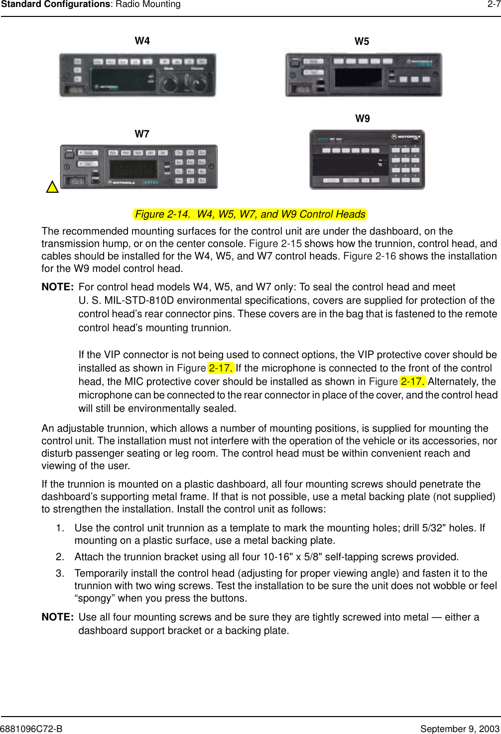
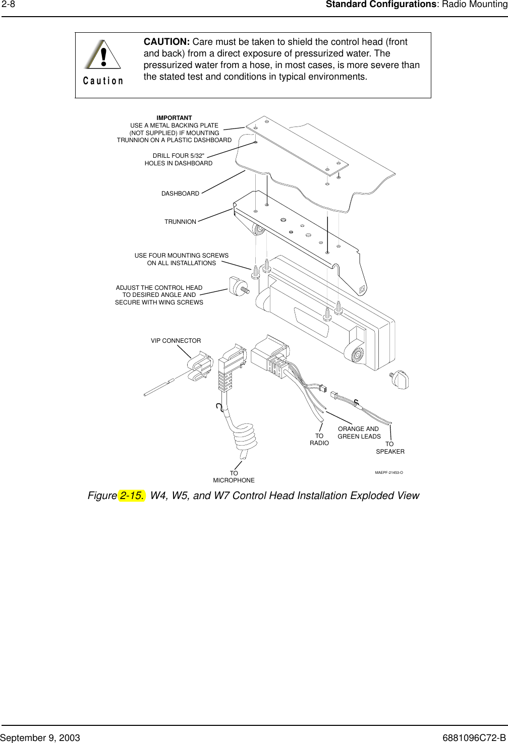
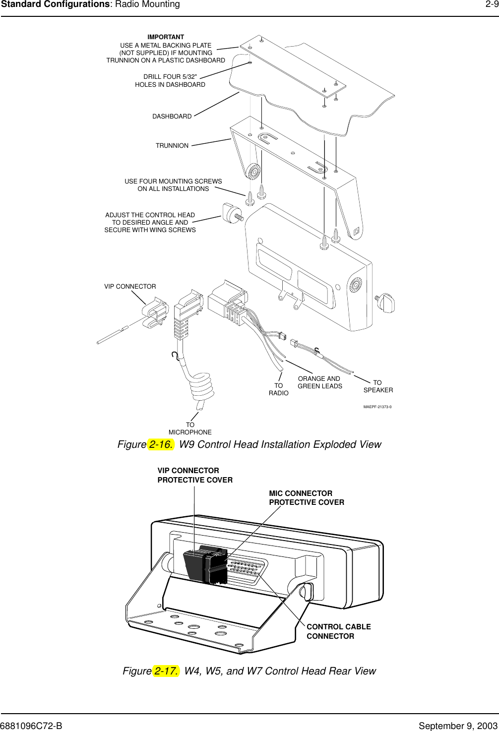
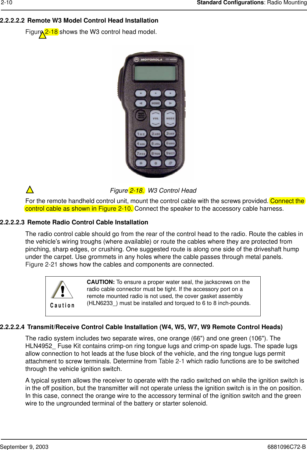
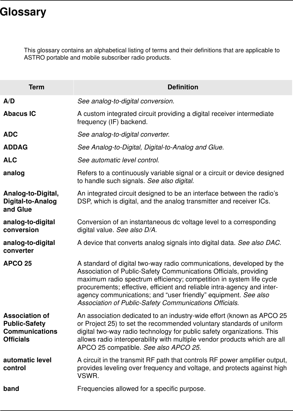
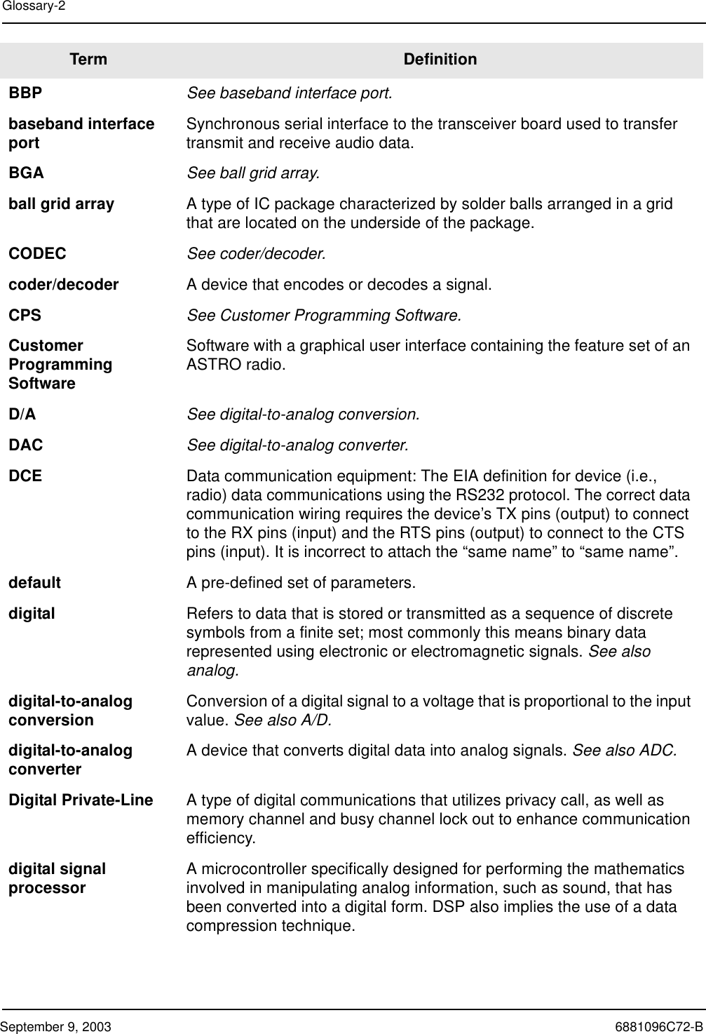
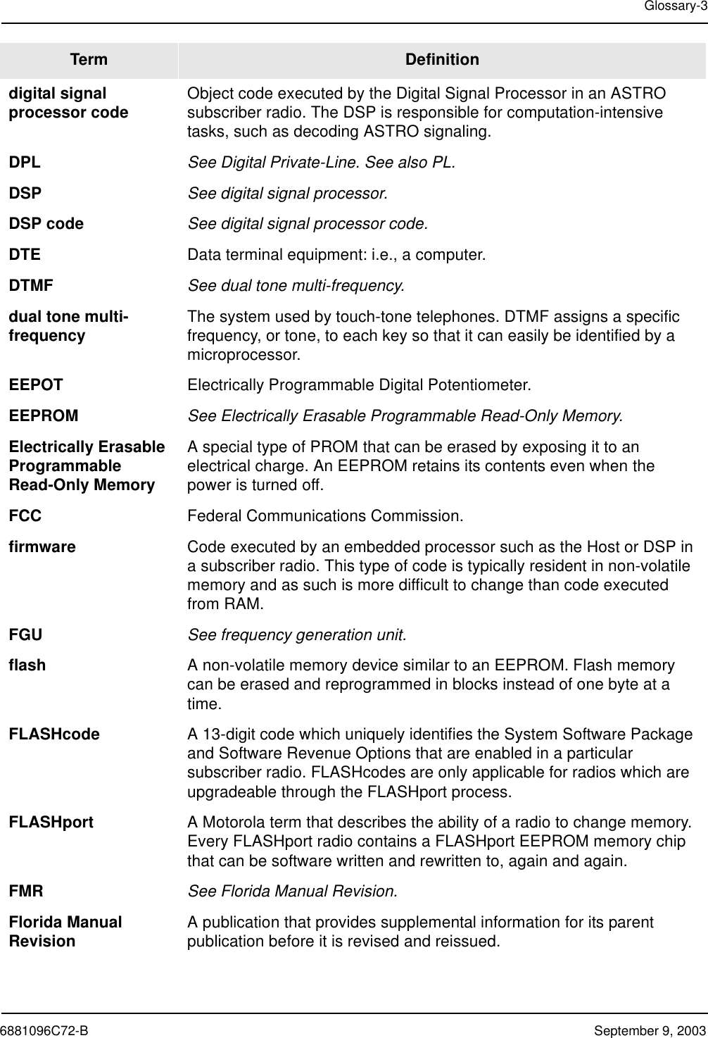
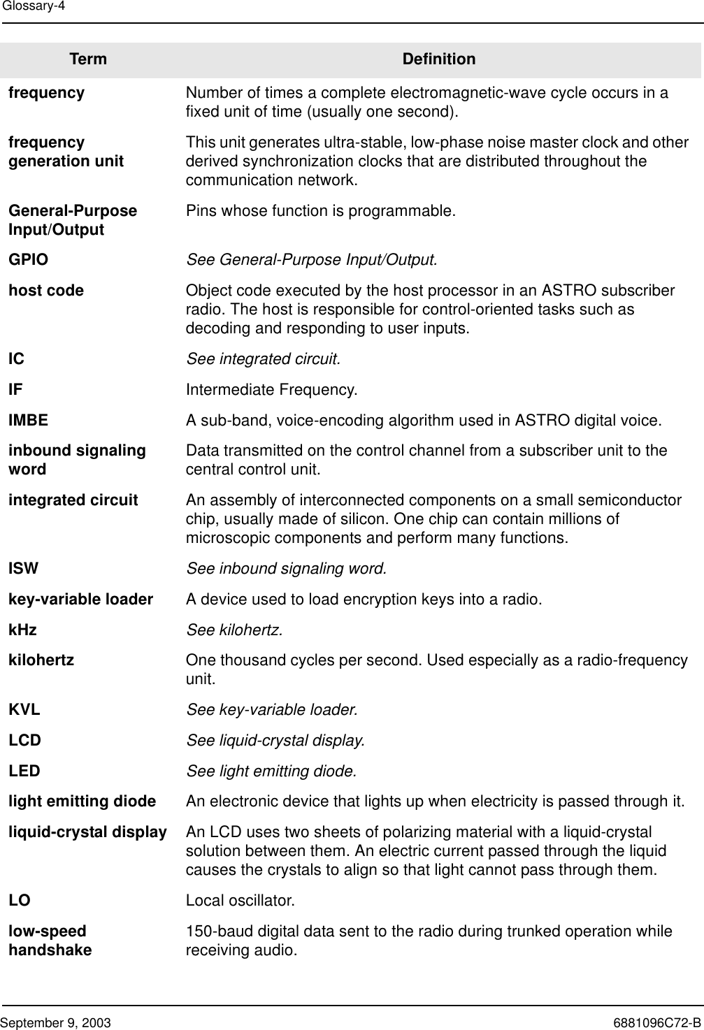
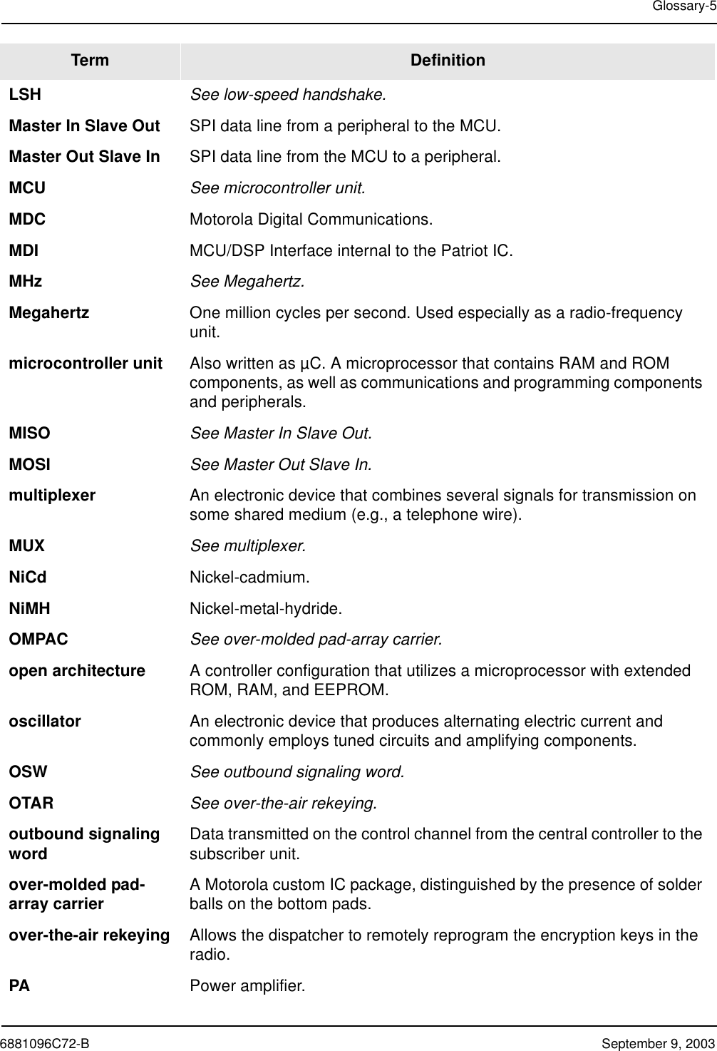
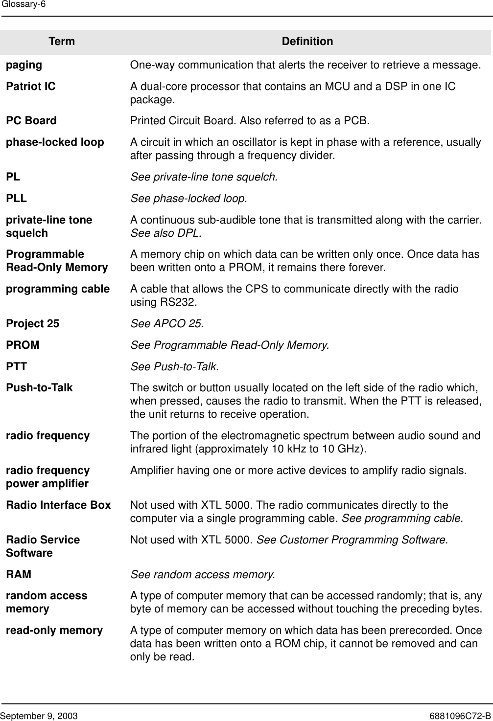
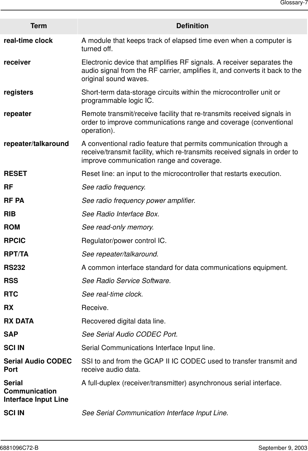
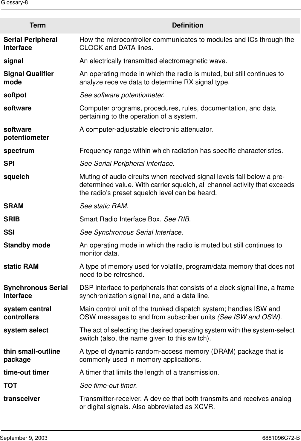
Motorola Solutions 92FT3808 Astro XTL5000 Digital Mobile Radio User Manual

Motorola Solutions, Inc. Astro XTL5000 Digital Mobile Radio

Contents

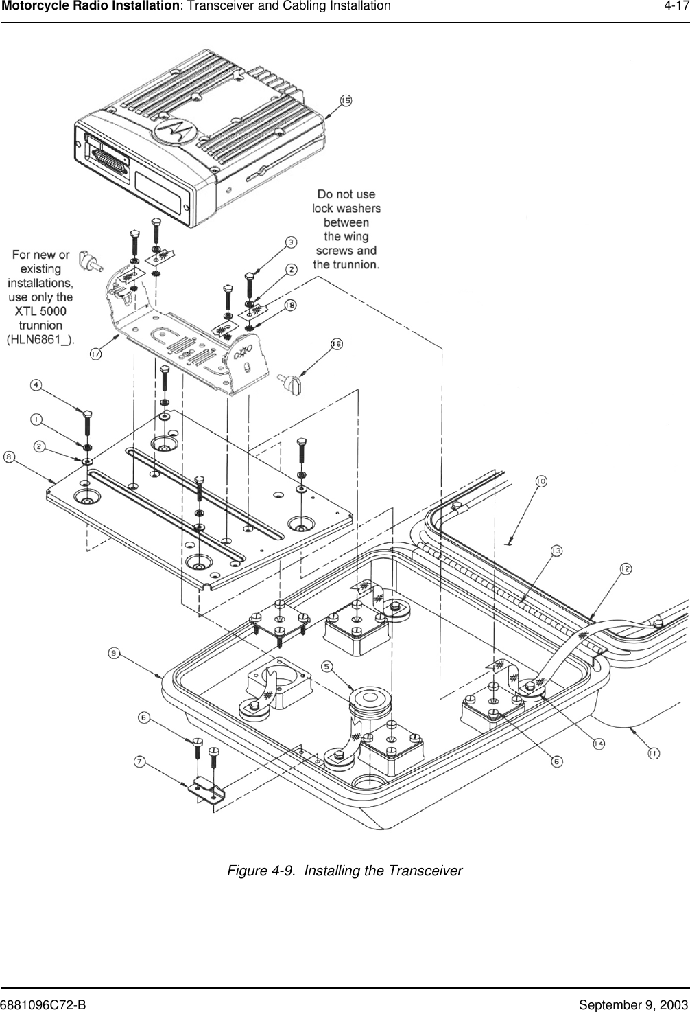
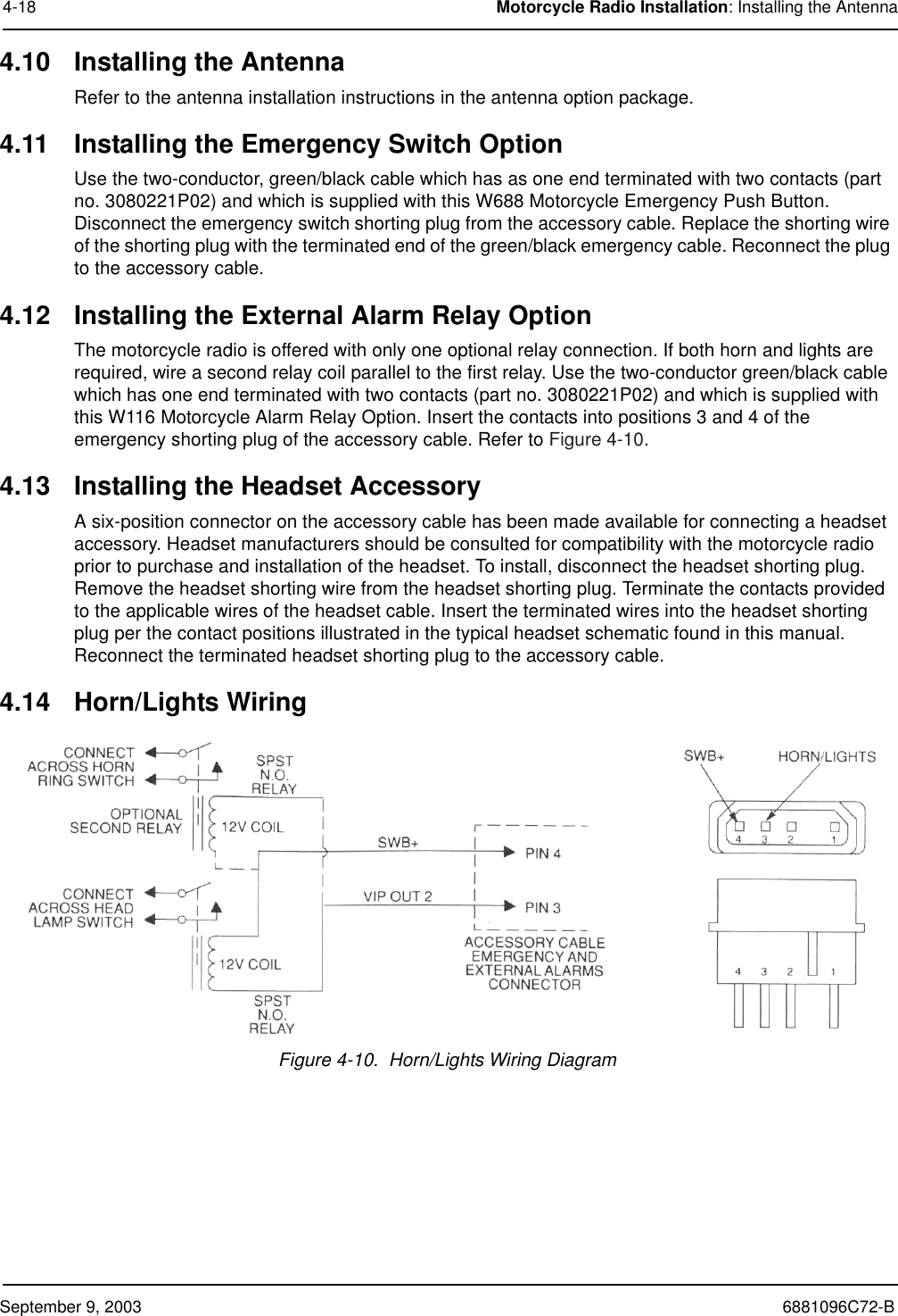
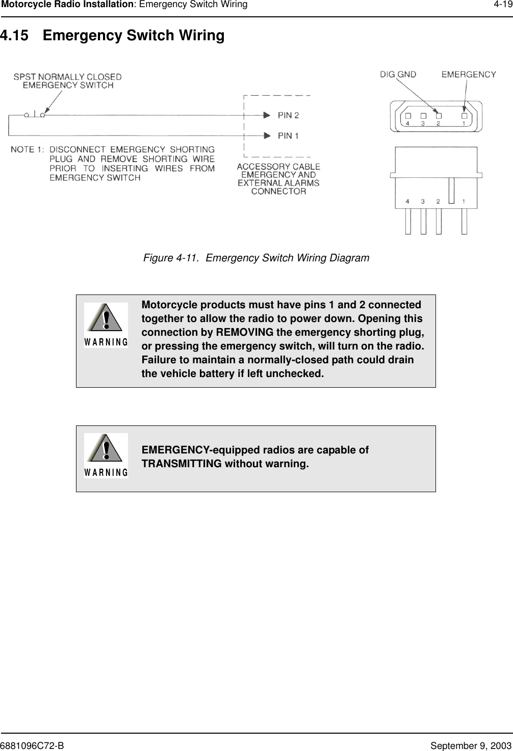
Ex8c Installation Manual

Installation ManualASTRO®  XTLTM 5000Digital Mobile Radio
izTitle Page ® XTL™ 5000Digital Mobile RadioInstallation ManualMotorola, Inc.8000 West Sunrise BoulevardFort Lauderdale, Florida 33322 6881096C72-B
iiForewordThis manual covers all models of the ASTRO®  XTL™ 5000 digital mobile radios (models W3, W4, W5, W7, and W9), unless otherwise specified. It includes all the information necessary to maintain peak product performance and maximum working time, using levels 1 and 2 maintenance procedures. This level of service goes down to the board replacement level and is typical of some local service centers, self-maintained customers, and distributors.For details on radio operation or component-level troubleshooting, refer to the applicable manuals available separately. A list of related publications is provided in the section “Related Publications,” on page vii.Product Safety and RF Exposure ComplianceSee “Installation Requirements for Compliance with Radio Frequency (RF) Energy Exposure Safety Standards,” on page iii.Manual RevisionsChanges which occur after this manual is printed are described in FMRs (Florida Manual Revisions). These FMRs provide complete replacement pages for all added, changed, and deleted items. To obtain FMRs, go to https://businessonline.motorola.com.Parts OrderingSee Appendix A: Replacement Parts Ordering for information on how to obtain replacement parts. For part numbers, refer to the ASTRO XTL 5000 Digital Mobile Radio Basic Service Manual (Motorola publication part number 6881096C73).Computer Software CopyrightsThe Motorola products described in this manual may include copyrighted Motorola computer programs stored in semiconductor memories or other media. Laws in the United States and other countries preserve for Motorola certain exclusive rights for copyrighted computer programs, including, but not limited to, the exclusive right to copy or reproduce in any form the copyrighted computer program. Accordingly, any copyrighted Motorola computer programs contained in the Motorola products described in this manual may not be copied, reproduced, modified, reverse-engineered, or distributed in any manner without the express written permission of Motorola. Furthermore, the purchase of Motorola products shall not be deemed to grant either directly or by implication, estoppel, or otherwise, any license under the copyrights, patents or patent applications of Motorola, except for the normal non-exclusive license to use that arises by operation of law in the sale of a product.Document CopyrightsNo duplication or distribution of this document or any portion thereof shall take place without the express written permission of Motorola. No part of this manual may be reproduced, distributed, or transmitted in any form or by any means, electronic or mechanical, for any purpose without the express written permission of Motorola.DisclaimerThe information in this document is carefully examined, and is believed to be entirely reliable. However, no responsibility is assumed for inaccuracies. Furthermore, Motorola reserves the right to make changes to any products herein to improve readability, function, or design. Motorola does not assume any liability arising out of the applications or use of any product or circuit described herein; nor does it cover any license under its patent rights nor the rights of others.TrademarksMOTOROLA, the Stylized M logo, FLASHport, and ASTRO are registered in the US Patent & Trademark Office. All other product or service names are the property of their respective owners.© Motorola, Inc. 2003.
iiiInstallation Requirements for Compliance withRadio Frequency (RF) Energy Exposure Safety StandardsATTENTION!This radio is intended for use in occupational/controlled conditions, where users have full knowledge of their exposure and can exercise control over their exposure to meet FCC limits. This radio device is NOT authorized for general population, consumer, or any other use.To ensure compliance to RF Energy Safety Standards:• Install only Motorola approved antennas and accessories• Be sure that antenna installation is per “Antenna Installation,” on page 2-14 of this manual• Be sure that Product Safety and RF Safety Booklet enclosed with this radio is available to the end user upon completion of the installation of this radio Before using this product, the operator must be familiar with the RF energy awareness information and operating instructions in the Product Safety and RF Exposure booklet enclosed with each radio (Motorola Publication part number 68P81095C99) to ensure compliance with Radio Frequency (RF) energy exposure limits. For a list of Motorola-approved antennas and other accessories, visit the following web site which lists approved accessories for your radio model:  http://www.motorola.com/cgiss/index.shtml.
This Page Intentionally Left Blankiv
Table of Contents v6881096C72-B September 9, 2003Table of ContentsForeword.........................................................................................................iiProduct Safety and RF Exposure Compliance............................................................................................iiManual Revisions ........................................................................................................................................iiParts Ordering .............................................................................................................................................iiComputer Software Copyrights ...................................................................................................................iiDocument Copyrights..................................................................................................................................iiDisclaimer....................................................................................................................................................iiTrademarks .................................................................................................................................................iiInstallation Requirements for Compliance withRadio Frequency (RF) Energy Exposure Safety Standards......................iiiMobile Radio Model Numbering Scheme.....................................................xCommercial Warranty ...................................................................................xiLimited Warranty ........................................................................................................................................xiMOTOROLA COMMUNICATION PRODUCTS................................................................................xiI. What This Warranty Covers And For How Long .....................................................................xiII. General Provisions.................................................................................................................xiIII. State Law Rights ..................................................................................................................xiiIV. How To Get Warranty Service .............................................................................................xiiV. What This Warranty Does Not Cover....................................................................................xiiVI. Patent And Software Provisions ......................................................................................... xiiiVII. Governing Law................................................................................................................... xiiiChapter 1 Introduction ......................................................................... 1-11.1 Mobile Radio Description............................................................................................................... 1-11.1.1 Dimensions ....................................................................................................................... 1-11.2 Standard Configurations ................................................................................................................ 1-11.2.1 Dash Mount Configuration ................................................................................................ 1-11.2.2 Remote Mount Configuration............................................................................................ 1-21.2.3 Dual Control Configuration ............................................................................................... 1-21.3 Motorcycle Configurations ............................................................................................................. 1-21.4 Base/Control Stations.................................................................................................................... 1-21.5 Tools Required for XTL 5000 Installations..................................................................................... 1-3Chapter 2 Standard Configurations.................................................... 2-12.1 Planning the Installation................................................................................................................. 2-12.1.1 Installation Examples........................................................................................................ 2-12.1.2 Wiring Diagrams ............................................................................................................... 2-22.2 Radio Mounting.............................................................................................................................. 2-42.2.1 Dash Mount with Trunnion................................................................................................ 2-52.2.2 Remote Mount with Trunnion............................................................................................ 2-6
vi Table of ContentsSeptember 9, 2003 6881096C72-B2.2.2.1 Transceiver..............................................................................................................2-62.2.2.2 Control Head and Remote Mount Cabling............................................................... 2-62.2.3 Locking Kit (Optional) .....................................................................................................2-132.3 Power Cable ................................................................................................................................ 2-132.4 Ignition Cable............................................................................................................................... 2-142.5 Antenna Installation ..................................................................................................................... 2-142.5.1 Selecting an Antenna Site/Location on a Metal Body Vehicle........................................ 2-152.5.2 Mini-UHF Connection ..................................................................................................... 2-152.6 Speaker ...................................................................................................................................... 2-172.7 Microphone Hang-Up Clip ........................................................................................................... 2-172.7.1 Standard Hang-Up Clip................................................................................................... 2-172.7.2 Handheld Hang-Up Box (W3 Model) .............................................................................. 2-182.8 Completing the Installation .......................................................................................................... 2-18Chapter 3 Options and Accessories Installation ............................... 3-13.1 VIP Overview................................................................................................................................. 3-13.1.1 VIP Output Connections ................................................................................................... 3-13.1.2 VIP Input Connections......................................................................................................3-23.2 Remote-Mount Accessory Installations for W4/5/7/9 Models ........................................................ 3-23.2.1 Emergency Pushbutton, Footswitch, Horn Relay, and Light Relay Installation ............... 3-33.2.1.1 Emergency Pushbutton or Footswitch Installation................................................... 3-33.2.1.2 Horn (External Alarm) Relay Installation ................................................................. 3-43.2.1.3 Lights (External Alarm) Relay Installation................................................................ 3-43.3 Dash-Mount Accessory Installations for W4/5/7/9 Models ............................................................ 3-43.3.1 MDC Emergency Pushbutton or Footswitch Installation................................................... 3-43.3.2 Horn and Lights (External Alarms) Relays........................................................................ 3-53.4 Remote-Mount Accessory Installations for W3 Model................................................................... 3-53.4.1 MDC Emergency Pushbutton or Footswitch Installation for W3 with Remote Cable Assembly3-63.4.2 Horn and Lights (External Alarms) Relays Installation for W3 with Remote Cable Assembly3-63.5 Accessory Connector Assembly Details (P2) ................................................................................ 3-73.5.1 Installation into the Vehicle............................................................................................... 3-73.5.2 Installation onto the Radio ................................................................................................3-73.5.3 Disassembly and Assembly.............................................................................................. 3-83.5.3.1 Disassembly ............................................................................................................ 3-83.5.3.2 Assembly .................................................................................................................3-83.5.4 Adapter Cable................................................................................................................... 3-93.5.5 Rear Accessory Jack Connection................................................................................... 3-10Chapter 4 Motorcycle Radio Installation ............................................ 4-14.1 Motorcycle Radio Description........................................................................................................ 4-14.1.1 Transceiver Enclosure......................................................................................................4-14.1.2 Control/Display Unit.......................................................................................................... 4-14.1.3 Control Head Cable .......................................................................................................... 4-14.1.4 Microphone....................................................................................................................... 4-14.1.5 External Speaker .............................................................................................................. 4-14.1.6 Headset Capability............................................................................................................ 4-24.1.7 Antenna ............................................................................................................................ 4-24.1.8 Ignition Wire...................................................................................................................... 4-24.2 Installation Overview ..................................................................................................................... 4-2
Table of Contents vii6881096C72-B September 9, 20034.2.1 General ............................................................................................................................. 4-24.2.2 Important Installation Hints ...............................................................................................4-34.2.3 Parts Identification ............................................................................................................ 4-34.2.4 Order of Installation .......................................................................................................... 4-34.3 Installing the Universal Mounting Plate.......................................................................................... 4-44.4 Installing the Speaker and Control Head ....................................................................................... 4-54.4.1 Handlebar Installation with Speaker and Control Head Mounted Together...................... 4-64.4.2 Fuel Tank Console Installation with Speaker and Control Head Mounted Together ........ 4-74.4.3 Handlebar Installation with Speaker and Control Head Mounted Separately................... 4-94.4.4 Fuel Tank Console Installation with Speaker and Control Head Mounted Separately ... 4-104.5 Installing the Speaker .................................................................................................................. 4-104.6 Installing the Microphone Hang-Up Clip ...................................................................................... 4-114.6.1 Extension Bracket Mounting ........................................................................................... 4-114.6.2 Speaker/Control Head Bracket Side Mounting ............................................................... 4-114.6.3 Other Hang-Up Clip Mounting ........................................................................................ 4-114.7 Installing Cables .......................................................................................................................... 4-124.8 Installing the Weather-Resistant Enclosure................................................................................. 4-134.9 Transceiver and Cabling Installation............................................................................................ 4-144.9.1 Installing Cabling in the Enclosure.................................................................................. 4-144.9.2 Installing the Transceiver................................................................................................ 4-154.10 Installing the Antenna .................................................................................................................. 4-184.11 Installing the Emergency Switch Option ......................................................................................4-184.12 Installing the External Alarm Relay Option ..................................................................................4-184.13 Installing the Headset Accessory................................................................................................. 4-184.14 Horn/Lights Wiring ....................................................................................................................... 4-184.15 Emergency Switch Wiring............................................................................................................ 4-19Chapter 5 Finishing the Installation: Cable Connection................... 5-1Appendix A Replacement Parts Ordering..............................................A-1A.1 Basic Ordering Information ............................................................................................................A-1A.2 Motorola Online .............................................................................................................................A-1A.3 Mail Orders ....................................................................................................................................A-1A.5 Fax Orders.....................................................................................................................................A-2A.6 Parts Identification .........................................................................................................................A-2A.7 Product Customer Service.............................................................................................................A-2Glossary.........................................................................................Glossary-1Index.....................................................................................................Index-1Related PublicationsASTRO XTL 5000 Digital Mobile Radio Model W3 User’s Guide ................................................6881096C67ASTRO XTL 5000 Digital Mobile Radio Models W4, W5, W7, and W9 User’s Guide ................6881096C68ASTRO XTL 5000 Digital Mobile Radio Basic Service Manual ...................................................6881096C73CPS Programming Installation Guide ..........................................................................................6881095C44ASTRO Digital Spectra Mobile Radios Dual Control Head Radio System Service Manual.........6881091C78Spectra Control Station Installation Manual ................................................................................6880101W87
viii List of FiguresSeptember 9, 2003 6881096C72-BList of FiguresFigure 1-1. Front View of Dash Mount Radio.......................................................................................... 1-1Figure 1-2. Side View of Dash Mount Radio ........................................................................................... 1-1Figure 1-3. Dash Mount Configuration.................................................................................................... 1-1Figure 1-4. Remote Mount Configuration................................................................................................ 1-2Figure 2-1. Mounting Flexibility in Middle Console.................................................................................. 2-1Figure 2-2. On Top or Under Dash Mounting.......................................................................................... 2-1Figure 2-3. Remote Mount–Control Head in Console............................................................................. 2-1Figure 2-4. In Dash Mounting.................................................................................................................. 2-1Figure 2-5. Remote Mount–Control Head in Dash.................................................................................. 2-1Figure 2-6. Remote Mount–Control Head on Top or Under Dash........................................................... 2-1Figure 2-7. Radio Installation (Dash Mount) Using W4, W5, or W7 Control Heads................................ 2-2Figure 2-8. Radio Installation (Remote) Using W4, W5, W7, or W9 Control Heads ............................... 2-3Figure 2-9. Radio Installation (Dash Mount) Using W3 Control Heads................................................... 2-3Figure 2-10. Radio Installation (Remote) Using W3 Control Heads.......................................................... 2-4Figure 2-11. Trunnion Orientation ............................................................................................................. 2-5Figure 2-12. Transmission Hump Trunnion Mounting ............................................................................... 2-5Figure 2-13. Below Dash Trunnion Mounting............................................................................................ 2-6Figure 2-14. W4, W5, W7, and W9 Control Heads ................................................................................... 2-7Figure 2-15. W4, W5, and W7 Control Head Installation Exploded View ................................................. 2-8Figure 2-16. W9 Control Head Installation Exploded View ....................................................................... 2-9Figure 2-17. W4, W5, and W7 Control Head Rear View........................................................................... 2-9Figure 2-18. W3 Control Head ................................................................................................................ 2-10Figure 2-19. Fuseholder Assembly for Orange and Green Control Cables .............................................2-11Figure 2-20. Locking Kit (Optional) ......................................................................................................... 2-13Figure 2-21. Cabling Interconnect Diagram for Remote Mount .............................................................. 2-13Figure 2-22. Cabling Interconnect Diagram for Dash Mount................................................................... 2-14Figure 2-23. Mini-UHF Connection ......................................................................................................... 2-16Figure 2-24. Mini-UHF Connector Tool ................................................................................................... 2-16Figure 2-25. Speaker Mounting............................................................................................................... 2-17Figure 3-1. VIP Connector Detail ............................................................................................................ 3-3Figure 3-2. Emergency Switch Wiring Diagram for W4/5/7/9.................................................................. 3-4Figure 3-3. Horn/Light Wiring Diagram for W4/5/7/9...............................................................................3-5Figure 3-4. Emergency Switch Wiring Diagram for W3........................................................................... 3-6Figure 3-5. Horn/Light Wiring Diagram for W3........................................................................................ 3-6Figure 3-6. Exploded View of Accessory Connector Assembly (P2) ...................................................... 3-8Figure 3-7. Rear Accessory Connector Audio Configuration .................................................................. 3-9Figure 3-8. Rear Accessory Connector Data Configuration.................................................................... 3-9Figure 3-9. Rear Accessory Jack Pin Configuration (J2) (Radio Side) ................................................. 3-10Figure 4-1. Universal Mounting Plate Installation (Part of Radio Enclosure Kit) ..................................... 4-4Figure 4-2. Handlebar Installation with Speaker and Control Head Mounted Together .......................... 4-6Figure 4-3. Fuel Tank Console Installation with Speaker and Control Head Mounted Together ............. 4-8Figure 4-4. Handlebar Installation with Speaker and Control Head Mounted Separately ....................... 4-9Figure 4-5. Fuel Tank Console Installation with Speaker and Control Head Mounted Separately........ 4-10Figure 4-6. Cable Routing..................................................................................................................... 4-12Figure 4-7. Weather-Resistant Enclosure Installation........................................................................... 4-13Figure 4-8. Installing Cables ................................................................................................................. 4-15Figure 4-9. Installing the Transceiver.................................................................................................... 4-17Figure 4-10. Horn/Lights Wiring Diagram................................................................................................ 4-18Figure 4-11. Emergency Switch Wiring Diagram .................................................................................... 4-19
List of Tables ix6881096C72-B September 9, 2003List of TablesTable 2-1. Radio Functions Connections...................................................................................2-11Table 2-2. Fuse Assembly for Orange and Green Leads Parts List ..........................................2-12Table 3-1. VIP Output Connections .............................................................................................3-1Table 3-2. VIP Input Connections ................................................................................................3-2Table 3-3. Rear Accessory Jack Pin Functions .........................................................................3-11Table 3-4. Rear Connector and Front Connector Naming Schemes .........................................3-12Table 3-5. How to Connect to a Computer1 (DTE Device) ........................................................3-12Table 4-1. Transceiver Installation Parts List .............................................................................4-16
September 9, 2003 6881096C72-BxMobile Radio Model Numbering Scheme Mobile Radio Model Numbering SchemePosition 1 - Type of UnitM =  Mobile L  =  Table Top StationPositions 2 & 3 - Model SeriesPosition 4 - Frequency BandLess than 29.7MHz29.7 to 35.99MHz36 to 41MHz42 to 50MHz300 to 345MHz66 to 80MHz74 to 90MHzProduct Specific    VHF Range136 to 162MHz146 to 178MHz174 to 210MHz190 to 235MHz330 to 370MHz366 to 410MHz403 to 437MHz438 to 482MHz470 to 620MHzProduct Specific  UHF Range806 to 870MHz*825 to 870MHz896 to 941MHz403-470MHz1.0 to 1.6GHz1.5 to 2.0GHzPosition 5 - Power Level0 to 0.7 Watts0.7 to 0.9 Watts1.0 to 3.9 Watts4.0 to 5.0 Watts5.1 to 6.0 Watts6.1 to 10 Watts10.1 to 15 Watts16 to 25 WattsPosition 6 - Physical PackagesRF Modem OperationReceiver OnlyStandard Control; No DisplayStandard Control; With DisplayLimited Keypad; No DisplayLimited Keypad; With DisplayFull Keypad; No DisplayFull Keypad; With DisplayLimited Controls; No DisplayLimited Controls; Basic DisplayLimited Controls; Limited DisplayRotary Controls; Standard DisplayEnhanced Controls; Enhanced DisplayLow Profile; No DisplayLow Profile; Basic DisplayLow Profile; Basic Display, Full KeypadTranceiver with Selectable Control HeadVDV Control HeadControl Head #2Position 7 - Channel Spacing0 =1 = 5KHz2 = 6.25KHz3 = 10KHz4 = 12.5KHz5 = 15KHz6 = 20/25KHz7 = 30KHz8 = 12.5/25KHz9 = Variable/ProgrammableTypical Model Number:Position:Position 8 - Primary OperationConventional/SimplexConventional/DuplexTrunked Twin TypeDual Mode TrunkedDual Mode Trunked/DuplexTrunked Type ITrunked Type IIFDMA* Digital Dual ModeTDMA** Digital Dual ModeSingle SidebandGlobal Positioning Satellite CapableAmplitude Companded Sideband (ACSB)Digital DispatchProgrammableDigital InterconnectDigital Multi-Service9600 CapableTDMA* FDMA = Frequency Division Multiple Access** TDMA = Time Division Multiple AccessPosition 9 - Primary System TypeConventionalPrivacy PlusClear SMARTNETAdvanced Conventional Stat-AlertEnhanced Privacy PlusNauganet 888 SeriesJapan Specialized Mobile Radio (JSMR)Multi-Channel Access (MCA)CoveragePLUSMPT1327* - PublicMPT1327* - PrivateRadiocomTone SignallingBinary SignallingPhonenetIDEN BasicIDEN Advanced FeatureJSMR DigitalLTR ProtocolSingle SidebandProgrammableSecure ConventionalSecure SMARTNETTETRASmartZone* MPT = Ministry of Posts and TelecommunicationsPosition 10 - Feature Level1 = Basic2 = Limited Package3 = Limited Plus4 = Intermediate5 = Standard Package6 = Standard Plus7 = Expanded Package8 = Expanded Plus9 = Full Feature/      ProgrammablePosition 11 - VersionVersion Letter (Alpha) - Major ChangePosition 12 - Unique Model VariationsC = CenelecN = Standard PackagePositions 13 - 16SP Model Suffix1 23 4 5 6 7 8 9 10 11 1213141516M20 U RS 9 P W 1 A N S P 0 120 = XTL 5000ABCDEFGHJKLM============NPQRSTUVWXYZ============A BCDEFGH========26 to 35 Watts36 to 60 Watts61 to 110 WattsUp to 125 Watts1-25 Watts25-40 Watt25-45 Watt10-35 WattJ KLMNPQR========A BCDEFGHJKLMNPQRSTUVW=====================A BCDEFGHJKLMNPQRST==================A BCDEFGHJKLMNPQRSTUVWXYZ2=========================MAEPF-27634-O* For XTL 5000 "U" in Position 4 represents     764-870MHz.Note: Values represented are not absolute,    and are given to indicate range only.Note: Values represented are not absolute,    and are given to indicate range only.
6881096C72-B September 9, 2003Commercial Warranty xiCommercial WarrantyLimited WarrantyMOTOROLA COMMUNICATION PRODUCTSI. What This Warranty Covers And For How LongMOTOROLA INC. (“MOTOROLA”) warrants the MOTOROLA manufactured Communication Products listed below (“Product”) against defects in material and workmanship under normal use and service for a period of time from the date of purchase as scheduled below:Motorola, at its option, will at no charge either repair the Product (with new or reconditioned parts), replace it (with a new or reconditioned Product), or refund the purchase price of the Product during the warranty period provided it is returned in accordance with the terms of this warranty. Replaced parts or boards are warranted for the balance of the original applicable warranty period. All replaced parts of Product shall become the property of MOTOROLA.This express limited warranty is extended by MOTOROLA to the original end user purchaser only and is not assignable or transferable to any other party. This is the complete warranty for the Product manufactured by MOTOROLA. MOTOROLA assumes no obligations or liability for additions or modifications to this warranty unless made in writing and signed by an officer of MOTOROLA. Unless made in a separate agreement between MOTOROLA and the original end user purchaser, MOTOROLA does not warrant the installation, maintenance or service of the Product.MOTOROLA cannot be responsible in any way for any ancillary equipment not furnished by MOTOROLA which is attached to or used in connection with the Product, or for operation of the Product with any ancillary equipment, and all such equipment is expressly excluded from this warranty. Because each system which may use the Product is unique, MOTOROLA disclaims liability for range, coverage, or operation of the system as a whole under this warranty.II. General ProvisionsThis warranty sets forth the full extent of MOTOROLA'S responsibilities regarding the Product. Repair, replacement or refund of the purchase price, at MOTOROLA's option, is the exclusive remedy. THIS WARRANTY IS GIVEN IN LIEU OF ALL OTHER EXPRESS WARRANTIES. IMPLIED WARRANTIES, INCLUDING WITHOUT LIMITATION, IMPLIED WARRANTIES OF MERCHANTABILITY AND FITNESS FOR A PARTICULAR PURPOSE, ARE LIMITED TO THE DURATION OF THIS LIMITED WARRANTY. IN NO EVENT SHALL MOTOROLA BE LIABLE FOR DAMAGES IN EXCESS OF THE PURCHASE PRICE OF THE PRODUCT, FOR ANY LOSS OF USE, LOSS OF TIME, INCONVENIENCE, COMMERCIAL LOSS, LOST PROFITS OR SAVINGS OR OTHER INCIDENTAL, SPECIAL OR CONSEQUENTIAL DAMAGES ARISING OUT OF THE USE OR INABILITY TO USE SUCH PRODUCT, TO THE FULL EXTENT SUCH MAY BE DISCLAIMED BY LAW.ASTRO XTL 5000 Digital Mobile Radio One (1) YearProduct Accessories One (1) Year
September 9, 2003 6881096C72-Bxii Commercial Warranty III. State Law RightsSOME STATES DO NOT ALLOW THE EXCLUSION OR LIMITATION OF INCIDENTAL OR CONSEQUENTIAL DAMAGES OR LIMITATION ON HOW LONG AN IMPLIED WARRANTY LASTS, SO THE ABOVE LIMITATION OR EXCLUSIONS MAY NOT APPLY.This warranty gives specific legal rights, and there may be other rights which may vary from state to state.IV. How To Get Warranty ServiceYou must provide proof of purchase (bearing the date of purchase and Product item serial number) in order to receive warranty service and, also, deliver or send the Product item, transportation and insurance prepaid, to an authorized warranty service location. Warranty service will be provided by Motorola through one of its authorized warranty service locations. If you first contact the company which sold you the Product, it can facilitate your obtaining warranty service. You can also call Motorola at 1-888-567-7347 US/Canada.V. What This Warranty Does Not CoverA. Defects or damage resulting from use of the Product in other than its normal and customary manner.B. Defects or damage from misuse, accident, water, or neglect.C. Defects or damage from improper testing, operation, maintenance, installation, alteration, modification, or adjustment.D. Breakage or damage to antennas unless caused directly by defects in material workmanship.E. A Product subjected to unauthorized Product modifications, disassemblies or repairs (includ-ing, without limitation, the addition to the Product of non-Motorola supplied equipment) which adversely affect performance of the Product or interfere with Motorola’s normal warranty inspection and testing of the Product to verify any warranty claim.F. Product which has had the serial number removed or made illegible.G. Rechargeable batteries if:- any of the seals on the battery enclosure of cells are broken or show evidence of tamper-ing.- the damage or defect is caused by charging or using the battery in equipment or service other than the Product for which it is specified.H. Freight costs to the repair depot.I. A Product which, due to illegal or unauthorized alteration of the software/firmware in the Prod-uct, does not function in accordance with MOTOROLA’s published specifications or the FCC type acceptance labeling in effect for the Product at the time the Product was initially distrib-uted from MOTOROLA.J. Scratches or other cosmetic damage to Product surfaces that does not affect the operation of the Product.K. Normal and customary wear and tear.
6881096C72-B September 9, 2003Commercial Warranty xiiiVI. Patent And Software ProvisionsMOTOROLA will defend, at its own expense, any suit brought against the end user purchaser to the extent that it is based on a claim that the Product or parts infringe a United States patent, and MOTOROLA will pay those costs and damages finally awarded against the end user purchaser in any such suit which are attributable to any such claim, but such defense and payments are conditioned on the following:A. that MOTOROLA will be notified promptly in writing by such purchaser of any notice of such claim;B. that MOTOROLA will have sole control of the defense of such suit and all negotiations for its settlement or compromise; andC. should the Product or parts become, or in MOTOROLA’s opinion be likely to become, the subject of a claim of infringement of a United States patent, that such purchaser will permit MOTOROLA, at its option and expense, either to procure for such purchaser the right to con-tinue using the Product or parts or to replace or modify the same so that it becomes nonin-fringing or to grant such purchaser a credit for the Product or parts as depreciated and accept its return. The depreciation will be an equal amount per year over the lifetime of the Product or parts as established by MOTOROLA.MOTOROLA will have no liability with respect to any claim of patent infringement which is based upon the combination of the Product or parts furnished hereunder with software, apparatus or devices not furnished by MOTOROLA, nor will MOTOROLA have any liability for the use of ancillary equipment or software not furnished by MOTOROLA which is attached to or used in connection with the Product. The foregoing states the entire liability of MOTOROLA with respect to infringement of patents by the Product or any parts thereof.Laws in the United States and other countries preserve for MOTOROLA certain exclusive rights for copyrighted MOTOROLA software such as the exclusive rights to reproduce in copies and distribute copies of such Motorola software. MOTOROLA software may be used in only the Product in which the software was originally embodied and such software in such Product may not be replaced, copied, distributed, modified in any way, or used to produce any derivative thereof. No other use including, without limitation, alteration, modification, reproduction, distribution, or reverse engineering of such MOTOROLA software or exercise of rights in such MOTOROLA software is permitted. No license is granted by implication, estoppel or otherwise under MOTOROLA patent rights or copyrights.VII. Governing LawThis Warranty is governed by the laws of the State of Illinois, USA.
September 9, 2003 6881096C72-Bxiv Commercial Warranty Notes
Chapter 1 IntroductionThis manual covers the installation procedures for ASTRO XTL 5000 mobile and motorcycle radios and accessories required to complete the radio system. The radio system consists of a control head, radio, antenna, microphone, speaker, cabling, and accessories.1.1 Mobile Radio Description1.1.1 DimensionsFigure 1-2 and Figure 1-1 show the basic dimensions of a dash mount XTL 5000 radio. The transceiver portion of a remote mount XTL 5000 is sized similarly. When installing the radio, make sure to plan the installation carefully and leave additional room in the rear of the radio for cabling and accessory connections; in the front of the radio for access, controls, and cabling (if remote mount); and to the sides of the radio so that you may access and install the trunnion wing screws.NOTE: The rear accessory connector adds 0.75 in. to the overall length.1.2 Standard Configurations1.2.1 Dash Mount ConfigurationIn the dash mounting version of the XTL 5000, the control head is mounted on the front of the transceiver housing. Electrical connection between the two takes place within the radio via a flexible circuit board between the connectors on the front of the transceiver and at the back of the control head.Figure 1-3.  Dash Mount ConfigurationFor details on this configuration, see Section 2.2.1 on page 2-5.Figure 1-1.  Front View of Dash Mount Radio Figure 1-2.  Side View of Dash Mount Radio8.5"7.1"9.1"2"3.5"
September 9, 2003 6881096C72-B1-2 Introduction: Motorcycle Configurations1.2.2 Remote Mount ConfigurationIn the remote control version, the transceiver and the control head are mounted separately in the vehicle. The control head is mounted in a remote trunnion near the operator. The transceiver is mounted by means of a trunnion or other mounting hardware. If the transceiver is located in a car trunk, be sure that secure mounting and sufficient cooling are provided. Do not cover the transceiver with baggage, blankets, etc.Figure 1-4.  Remote Mount ConfigurationFor details on this configuration, see Section 2.2.2 on page 2-6.1.2.3 Dual Control ConfigurationThe dual control head option allows two, separate, remotely operated control heads to operate and control the radio. For example, a fire truck could have a control head located in the cab and on the rear of the truck so that the radio could be operated from outside the vehicle.For details on this configuration, see the ASTRO Digital Spectra Mobile Radios Dual Control Head Radio System Service Manual (Motorola publication part number 6881091C78). 1.3 Motorcycle ConfigurationsThe ASTRO XTL 5000 motorcycle radio models provide most of the equipment needed for installing a standard ASTRO XTL 5000 radio on a motorcycle. Most of this radio system is standard equipment. See Chapter 4: Motorcycle Radio Installation for further information.1.4 Base/Control StationsThe base/control station option provides the radio with a desk microphone and power supply for use at a fixed location. All operations are the same as the mobile, except for the desk microphone.Choose a location for your base/control station as close as possible to where the antenna cable enters the building. Be sure an electric outlet is available. Make sure sufficient air can flow around the radio to permit adequate cooling.The antenna should be installed outside of the building, but never within two feet (for radios with less than 50 watts power output) or within three feet (for radios with 50 watts or higher power output) of station operators or bystanders.For more information, refer to the Spectra Control Station Installation Manual (Motorola publication part number 6880101W87).MAEPF-27638-O0PWRMode ScanPhon SelCallVolDIMHOMEXMITBUSY1234567890Sts MsgH/L MonDirRclDel
6881096C72-B September 9, 2003Introduction: Tools Required for XTL 5000 Installations 1-31.5 Tools Required for XTL 5000 InstallationsTool Part Number11/32 hex driver —RF cable tool HLN6695_Regular slot screwdriver of Phillips #2 —Pin removal tool 6680163F011/4 hex driver —
September 9, 2003 6881096C72-B1-4 IntroductionNotes
Chapter 2 Standard Configurations2.1 Planning the InstallationThe XTL 5000 radio operates only in negative ground electrical systems. Before starting the radio installation, make sure that the ground polarity of the vehicle is correct. Accidentally reversing the polarity will not damage the radio, but will cause the cable fuses to blow.Planning is the key to fast, easy radio installation. Before starting the installation, inspect the vehicle and determine how and where you intend to mount the antenna, radio, and accessories. Plan wire and cable runs to provide maximum protection from inching, crushing, and overheating.2.1.1 Installation ExamplesYour mobile two-way radio offers various methods of installation, including dash or remote mount (see Figure 2-1 through Figure 2-6). CAUTION Before installing any electrical equipment, check the vehicle manufacturer’s user manual.  The installation of this device should be completed by an authorized servicer or installer.Figure 2-1.  Mounting Flexibility in Middle Console Figure 2-2.  On Top or Under Dash MountingFigure 2-3.  Remote Mount–Control Head in Console Figure 2-4.  In Dash MountingFigure 2-5.  Remote Mount–Control Head in Dash Figure 2-6.  Remote Mount–Control Head on Top or Under DashRadioAntenna1/4-WavelengthBatterySpeakerRadioAntenna1/4-WavelengthBatterySpeakerRadioRadioBatterySpeakerControl HeadAntenna1/4-WavelengthRadioAntenna1/4-WavelengthBatterySpeakerRadioBatterySpeakerControl HeadAntenna1/4-WavelengthRadioBatterySpeakerControl HeadControl Head Antenna1/4-Wavelength
September 9, 2003 6881096C72-B2-2 Standard Configurations: Planning the Installation2.1.2 Wiring DiagramsFigure 2-7 through Figure 2-10 show the wiring diagrams for all the possible configurations. The title under each figure identifies which model control head is being shown. Identify which of these figures shows the configuration that you are installing, and use the diagram when planning the installation.Figure 2-7.  Radio Installation (Dash Mount) Using W4, W5, or W7 Control Heads (For complete pin configuration, see Figure 3-9.)PWRMode ScanPhon SelCallVolDIMHOMEXMITBUSY12345678 90Sts MsgH/L Mon DirRcl DelMICBATTERYHORN RELAYLIGHT RELAYMICCLIPSPEAKERMICEMERGENCYSWITCHFUSEFUSEBLOCK(+)(-)RED LEADFUSEFIREWALLHOLEMOUNTINGSCREWCONTROL HEAD**  MODEL W7 SHOWNANTENNA CONNECTION ANTENNAMAEPF-27612-OIGNITION CABLEP2(SEE J2PINOUT)DCPOWER CABLETRUNNIONJ2REAR ACCESSORY CONNECTOR1781413202126SPKR-SPKR+VIPOUT 212V(RELAY)VIPOUT 112V(RELAY)GROUNDEMERGENCYIGNITION
6881096C72-B September 9, 2003Standard Configurations: Planning the Installation 2-3Figure 2-8.  Radio Installation (Remote) Using W4, W5, W7, or W9 Control HeadsFigure 2-9.  Radio Installation (Dash Mount) Using W3 Control Heads(For complete pin configuration, see Figure 3-9.)PWRMode ScanPhon SelCallVolDIMHOMEXMITBUSY12345678 90Sts MsgH/L Mon DirRcl DelMICBATTERYHORN RELAYLIGHT RELAYMICCLIPSPEAKERMICEMERGENCYSWITCHGRN LEADFUSEBLOCKORG LEAD(+)(-)FUSEFUSE               REMOTE      MOUNT     CONTROL   CABLECONTROL HEAD**  MODEL W7 SHOWNMAEPF-27613-O12345 78101112 13 14 15 16 171918 20 21 23 24 26 27 28 29 30 31 32 3334 35 36 37 38 40 41 43 44 45 46 47 48 49 50VIP MIC RADIOVIP SECTION PIN OUT1   VIP OUT - 22   VIP OUT - 13   VIP IN - 2 *4   VIP IN - 15   DEK  DATA OUT    * EMERGENCY WITH JUMPER CHANGES TO CONTROL HEADS18   SWB +19   SWB +20   GROUND21   GROUND34   VIP OUT - 3 / DEK STROBE35   SWB +36   GROUND37   VIP IN - 3 / DEK DATA IN38   DEK CLOCKJ0103PORT ON BACK OF CONTROL HEADFIREWALLHOLEANTENNA CONNECTION ANTENNADC POWER CABLERADIOJ5P506 J6FUSEBATTERYLIGHT ORHORNRELAYSPEAKEREMERGENCYSWITCHFUSEBLOCK(+)(-)FUSEFIREWALLHOLEMOUNTINGSCREWCONTROL HEADANTENNA CONNECTION IGNITION CABLEDCPOWER CABLETRUNNIONHANG-UPBOXHANDHELDCONTROLHEADFUSEANTENNAMAEPF-27614-OJ2REAR ACCESSORY CONNECTORP2(SEE J2PINOUT)1781413202126SPKR-SPKR+VIPOUT 212V(RELAY)VIPOUT 112V(RELAY)GROUNDEMERGENCYIGNITIONJ5P506 J6
September 9, 2003 6881096C72-B2-4 Standard Configurations: Radio MountingFigure 2-10.  Radio Installation (Remote) Using W3 Control Heads2.2 Radio MountingThe mounting location must be accessible and visible. Select a location that will permit routing the RF antenna cable as directly as possible. NOTE: For optimum radio performance, orient the mounting trunnion as shown in Figure 2-11. For new or existing installations, use only the XTL 5000 trunnion (kit number: HLN6861_).CAUTION: DO NOT mount the radio on a plastic dashboard without first reinforcing the dashboard; the weight of the radio may crack or break the dashboard.CAUTION: DO NOT mount the radio on a flat or concave surface where the radio could be partially submersed in water. This is especially important if the cab area of the vehicle is cleaned by spraying with water. If the radio sits in water for a length of time, moisture may seep inside the radio and damage the electronic components.CAUTION: DO NOT allow water to stand in recessed areas of vertically mounted radios. Remove any moisture immediately to prevent it from seeping down into the radio.BATTERYLIGHT ORHORNRELAYSPEAKEREMERGENCYSWITCHFUSEBLOCK(+)(-)REMOTEMOUNT CONTROLCABLEMAEPF-27615-OFIREWALLHOLEANTENNA CONNECTION DC POWER CABLERADIOJ3REMOTE MOUNT ACCESSORY CONNECTORDIGGNDSPKR LO SPKRHIIGNITIONSWB+VIP OUT 2EMERNOTE 1NCBUS+NC NOTE 2 BUSYVIP OUT 1 BUS-NOTES:1.  TX AUDIO IN SP CUSTOMER APPLICATIONS.2.  DET AUDIO IN SP CUSTOMER APPLICATIONS.1234567815 14 13 12 11 10 9HANDHELDCONTROLHEADHANG-UPBOXIGNITION CABLEJ3PINOUTFUSEFUSEJ5P506 J6!C a u t i o n
6881096C72-B September 9, 2003Standard Configurations: Radio Mounting 2-5Figure 2-11.  Trunnion Orientation2.2.1 Dash Mount with Trunnion1. Select the location to mount your radio on the transmission hump (see Figure 2-12) or under the dash (see Figure 2-13). When mounting the trunnion on the transmission hump take care the transmission housing is not affected.2. Using the trunnion mounting bracket as a template, mark the positions of the holes on the mounting surface. Use the innermost four holes for a curved mounting surface such as the transmission hump, and the four outmost holes for a flat surface such as under the dash.3. Center punch the spots you have marked and realign the trunnion in position.4. Secure the trunnion mounting bracket with the four self-drilling screws provided (see Figure 2-12 and Figure 2-13).5. Ensure that the plastic guides are aligned (horizontal) to the grooves of the trunnion. Slide the radio into the grooves until it snaps into place (see Figure 2-12). Secure the radio with the two wing screws provided.Figure 2-12.  Transmission Hump Trunnion MountingRADIOFRONTAPPLIES TO RADIOS WITH INTEGRALOR REMOTE MOUNT CONTROL UNITSTabsTrunnionGrooveWing ScrewWing Screw Plastic GuidesThreaded Holefor Wing Screw
September 9, 2003 6881096C72-B2-6 Standard Configurations: Radio MountingFigure 2-13.  Below Dash Trunnion Mounting2.2.2 Remote Mount with Trunnion2.2.2.1  TransceiverFor a remote mount installation, the transceiver may be mounted anywhere in the vehicle, provided that the installation location is safe, follows the cautions mentioned at the beginning of this section, and is accessible for servicing/maintenance as well as cabling. A typical mounting location recommended by Motorola is in the vehicle’s trunk. The trunnion provided may still be used to mount the transceiver, and the mounting process is the same as for the dash mount installation (Section 2.2.1 on page 2-5). See Figure 2-8 for a remote W4, W5, W7, and W9 installation, and Figure 2-10 for a remote W3 installation.2.2.2.2  Control Head and Remote Mount CablingFor radios equipped with optional remote mount control heads, see Figure 2-8. For radios equipped with remote handheld control heads, see Figure 2-10. Choose a mounting location for the radio, considering accessibility, and control and antenna cable lengths. 2.2.2.2.1 Remote W4, W5, W7, and W9 Model Control Head InstallationFigure 2-14 shows each of the control head models.If you are required to insert any of the replaceable buttons available with these radios, refer to the XTL 5000 Basic Service Manual (Motorola publication part number 6881096C73) for further information.CAUTION Before installing any electrical equipment, check the vehicle manufacturer’s user manual.  The installation of this device should be completed by an authorized servicer or installer.TrunnionWing ScrewWing ScrewHoles forMicrophoneS-Hook
6881096C72-B September 9, 2003Standard Configurations: Radio Mounting 2-7Figure 2-14.  W4, W5, W7, and W9 Control HeadsThe recommended mounting surfaces for the control unit are under the dashboard, on the transmission hump, or on the center console. Figure 2-15 shows how the trunnion, control head, and cables should be installed for the W4, W5, and W7 control heads. Figure 2-16 shows the installation for the W9 model control head.NOTE: For control head models W4, W5, and W7 only: To seal the control head and meet U. S. MIL-STD-810D environmental specifications, covers are supplied for protection of the control head’s rear connector pins. These covers are in the bag that is fastened to the remote control head’s mounting trunnion.If the VIP connector is not being used to connect options, the VIP protective cover should be installed as shown in Figure 2-17. If the microphone is connected to the front of the control head, the MIC protective cover should be installed as shown in Figure 2-17. Alternately, the microphone can be connected to the rear connector in place of the cover, and the control head will still be environmentally sealed.An adjustable trunnion, which allows a number of mounting positions, is supplied for mounting the control unit. The installation must not interfere with the operation of the vehicle or its accessories, nor disturb passenger seating or leg room. The control head must be within convenient reach and viewing of the user.If the trunnion is mounted on a plastic dashboard, all four mounting screws should penetrate the dashboard’s supporting metal frame. If that is not possible, use a metal backing plate (not supplied) to strengthen the installation. Install the control unit as follows:1. Use the control unit trunnion as a template to mark the mounting holes; drill 5/32" holes. If mounting on a plastic surface, use a metal backing plate.2. Attach the trunnion bracket using all four 10-16" x 5/8" self-tapping screws provided.3. Temporarily install the control head (adjusting for proper viewing angle) and fasten it to the trunnion with two wing screws. Test the installation to be sure the unit does not wobble or feel “spongy” when you press the buttons.NOTE: Use all four mounting screws and be sure they are tightly screwed into metal — either a dashboard support bracket or a backing plate.W4W7W9W7W9W5W5
September 9, 2003 6881096C72-B2-8 Standard Configurations: Radio Mounting Figure 2-15.  W4, W5, and W7 Control Head Installation Exploded ViewCAUTION: Care must be taken to shield the control head (front and back) from a direct exposure of pressurized water. The pressurized water from a hose, in most cases, is more severe than the stated test and conditions in typical environments.!C a u t i o nIMPORTANTUSE A METAL BACKING PLATE(NOT SUPPLIED) IF MOUNTINGTRUNNION ON A PLASTIC DASHBOARDDRILL FOUR 5/32"HOLES IN DASHBOARDDASHBOARDTRUNNION03-00136756USE FOUR MOUNTING SCREWSON ALL INSTALLATIONSADJUST THE CONTROL HEADTO DESIRED ANGLE ANDSECURE WITH WING SCREWSVIP CONNECTORTOMICROPHONETO SPEAKERTORADIOORANGE AND GREEN LEADSMAEPF-21453-O
6881096C72-B September 9, 2003Standard Configurations: Radio Mounting 2-9Figure 2-16.  W9 Control Head Installation Exploded ViewFigure 2-17.  W4, W5, and W7 Control Head Rear ViewIMPORTANTUSE A METAL BACKING PLATE(NOT SUPPLIED) IF MOUNTINGTRUNNION ON A PLASTIC DASHBOARDDRILL FOUR 5/32"HOLES IN DASHBOARDDASHBOARDTRUNNION03-00136756USE FOUR MOUNTING SCREWSON ALL INSTALLATIONSADJUST THE CONTROL HEADTO DESIRED ANGLE ANDSECURE WITH WING SCREWSVIP CONNECTORTOMICROPHONETO SPEAKERTORADIOORANGE AND GREEN LEADSDESCRIPTIONTECHNICAL PUBLICATIONS DEPT.DWG. NO.MAEPF 21373MAEPF-21373-0VIP CONNECTORPROTECTIVE COVERCONTROL CABLECONNECTORMIC CONNECTORPROTECTIVE COVERILDE
September 9, 2003 6881096C72-B2-10 Standard Configurations: Radio Mounting2.2.2.2.2 Remote W3 Model Control Head InstallationFigure 2-18 shows the W3 control head model.Figure 2-18.  W3 Control HeadFor the remote handheld control unit, mount the control cable with the screws provided. Connect the control cable as shown in Figure 2-10. Connect the speaker to the accessory cable harness.2.2.2.2.3 Remote Radio Control Cable InstallationThe radio control cable should go from the rear of the control head to the radio. Route the cables in the vehicle’s wiring troughs (where available) or route the cables where they are protected from pinching, sharp edges, or crushing. One suggested route is along one side of the driveshaft hump under the carpet. Use grommets in any holes where the cable passes through metal panels. Figure 2-21 shows how the cables and components are connected. 2.2.2.2.4 Transmit/Receive Control Cable Installation (W4, W5, W7, W9 Remote Control Heads)The radio system includes two separate wires, one orange (66") and one green (106"). The HLN4952_ Fuse Kit contains crimp-on ring tongue lugs and crimp-on spade lugs. The spade lugs allow connection to hot leads at the fuse block of the vehicle, and the ring tongue lugs permit attachment to screw terminals. Determine from Table 2-1 which radio functions are to be switched through the vehicle ignition switch. A typical system allows the receiver to operate with the radio switched on while the ignition switch is in the off position, but the transmitter will not operate unless the ignition switch is in the on position. In this case, connect the orange wire to the accessory terminal of the ignition switch and the green wire to the ungrounded terminal of the battery or starter solenoid. CAUTION: To ensure a proper water seal, the jackscrews on the radio cable connector must be tight. If the accessory port on a remote mounted radio is not used, the cover gasket assembly (HLN6233_) must be installed and torqued to 6 to 8 inch-pounds.!C a u t i o n
6881096C72-B September 9, 2003Standard Configurations: Radio Mounting 2-11If either wire is to be connected in the vehicle’s battery compartment, pass the end of the wire through the same firewall hole that the red radio power cable uses. At this point, install a fuseholder assembly in both wires (see Figure 2-19); the following procedures apply to both green and orange wires:Figure 2-19.  Fuseholder Assembly for Orange and Green Control Cables• A fuse will need to be placed in-line for both the orange and green wires; consideration should be taken when deciding where to place the fuses so that they are easy to inspect. However, they should also be placed as close as possible to the battery or the vehicle’s ignition switch terminal.• After choosing the fuse locations, the fuse receptacles need to be installed. This is done by cut-ting the wire at the chosen location and stripping 1/8-inch of insulation on all loose ends. Make sure the wire will reach its intended destination.CAUTION: DO NOT connect either lead to the ungrounded terminal of the battery until you have finalized the installation and have been instructed to do so.Table 2-1.  Radio Functions ConnectionsConductor Green Orange Green Orange Green OrangeConnected to battery X X XConnected to ignition switch XXXIgnition switch controls No ignition switch control Transmitter ignition switch controlled Complete radio ignition switch controlledIn any application, trim and strip wires. Crimp on ring lug for battery connections. For ignition switch connections, crimp on ring or spade lug (whichever is required).!C a u t i o nSPADE OR RINGTONGUE LUG(RING TONGUELUG SHOWN)PLASTIC INSULATORFUSE HOLDER CAPMETAL FUSECLIPS CRIMPAND SOLDERTO WIRETO CONTROLHEADSPRINGFUSEPLASTIC INSULATORFUSE HOLDERMAEPF-21361-O
September 9, 2003 6881096C72-B2-12 Standard Configurations: Radio Mounting• Slide the plastic insulator fuseholder over the end of the wire that is connected to the cable kit. Insert the stripped end of that wire into one of the metal fuse clips, and crimp it closed onto the exposed wire. Solder it for a better electrical contact.• On the end of the loose wire, repeat the above crimping and soldering process with the remain-ing metal fuse clip.• Temporarily, install the fuse (both are 3-amp), into the fuse clips onto both sides of the fuse. Slide the spring over the remaining loose end of the wire. The spring should be followed by the plastic insulator fuseholder oriented as shown in Figure 2-19. Slide the plastic insulator fuse holder together, by first making sure the spring slips inside the plastic insulator fuseholder cap. Now, twist the fuseholders until they lock together. After assembly proves successful, remove the fuses until instructed to install them later.With the spring and plastic insulator fuseholder cap still in place on the loose portion of the wires (orange and green), insert the stripped end of the wire into the spade or ring tongue lug. Crimp and solder the lug as was done on the metal fuse clips above. 2.2.2.2.4.1 Transmitter Control Power Lead (Orange)Connect the orange lead to the ignition switch (recommended) or directly to the battery hot supply (see Figure 2-21).2.2.2.2.4.2 Receiver Control Power Lead (Green)Connect the green lead to the positive battery terminal (recommended) or the ignition switch (see Figure 2-21).Table 2-2.  Fuse Assembly for Orange and Green Leads Parts ListMotorola Part Number Description1482882A01 Insulator, Fuseholder Body1482883A01 Insulator, Fuseholder Cap2900136968 Lug2900824456 Lug, Ring Tongue2900865065 Lug, Ring Tongue4182885A01 Spring, Compression; Fuse4282884Q01 Clip, Fuse6500020404 Fuse, 3-Amp 250V (Qty. 2)
6881096C72-B September 9, 2003Standard Configurations: Power Cable 2-132.2.3 Locking Kit (Optional)If a locking kit is used (shown in Figure 2-20), position the lock bottom housing on the trunnion before installing the radio mounting screws. Then slip the top lock housing on and remove the key. You can install the lock on either side of the radio, and by rotating it 180°, you can also install it on dash installations.Figure 2-20.  Locking Kit (Optional)2.3 Power CableRoute the red radio power cable from the radio to the vehicle’s battery compartment, using accepted industry methods and standards. Be sure to grommet the firewall hole to protect the cable. Remove the 15-amp (P/N 6580283E06) or 20-amp (P/N 6580283E07) fuse from the fuseholder and connect the red lead of the radio power cable to the positive battery terminal using the hardware provided as shown in Figure 2-21 and Figure 2-22. Connect the black lead to a convenient solid chassis ground point. DO NOT connect the black lead directly to the battery’s negative terminal.Figure 2-21.  Cabling Interconnect Diagram for Remote MountExistingMountingScrewLockLockHousingHLN6372_ Locking KitRADIO COMPARTMENT OPERATOR COMPARTMENT VEHICLE BATTERYCOMPARTMENTA good chassis connection via the black primary power cable is essential for radio operation and to prevent damage to the radio and cable kit.  Connection to the vehicle frame is desirable.VEHICLE BATTERY15A OR 20AFUSEPART OFVEHICLEWIRINGVEHICLEIGNITION SWITCHON/ACCGROMMETGROMMET SEE NOTERADIO POWER CABLE(RED/BATTERY HOT)RECEIVERCONTROL CABLE (GRN)RADIO CONTROLCABLE (BLK/MULTI-CONDUCTOR)SPEAKERTRANSMITTERCONTROL CABLE (ORG)3A OR 4A  FUSEMICROPHONEVIPMICRADIO (ORG)(GRN)RADIO POWER CABLE (BLK/GROUND)RADIO(-)(+)CAUTIONNOTE:  For remote mount configurations, do not supply IGNITION at the radio’s rear accessory connector. IGNITION should be supplied according to Table 2-1.   (See Table 2-1 for combinations of wiring the Green and Orange Cables)The orange and green power cables connect to either the vehicle battery or the ignition switch. Connect the green cable directly to the battery. The receiver operateswhen the control head is on. Connect the orange cable to the ignition switch. The transmitter operates only when the ignition switch is on. Alternate connections:Connecting both green and orange cables to the battery allows the control head to turn the receiver and transmitter on or off.  Connecting both green and orange cablesto the ignition switch allows the ignition switch to turn the receiver and transmitter on or off.  (Alternator whine and other noise problems may occur.  Isolate the green cable with a Motorola relay, part #59-00813674.)MAEPF-27616-OREARCONNECTORI.B.
September 9, 2003 6881096C72-B2-14 Standard Configurations: Ignition CableFigure 2-22.  Cabling Interconnect Diagram for Dash Mount2.4 Ignition CableMotorola supplies an ignition sense cable and recommends that it be used with every mobile installation. The ignition sense cable allows the radio to be turned on and off with the vehicle ignition switch, and allows the radio to “remember” the state of the radio on/off switch, even if it is changed while the vehicle is off. • For radio ON/OFF control independent of the ignition switch, connect the red ignition cable (orange for remote) (pin 25 of accessory connector) to “battery hot” at the vehicle fuse block.• For radio ON/OFF control via the ignition switch, connect the red ignition cable (orange for remote) to “ignition” at the fuse block.Note that for remote mount installations, the green and orange leads are connected, not the red lead from the rear of the radio. See Table 2-1.The ignition sense cable uses either a 3-amp (P/N 6580283E01) or 4-amp (P/N 6580283E02) fuse.For other considerations when connecting the ignition cable, see the XTL 5000 Basic Service Manual (Motorola publication part number 6881096C73).2.5 Antenna InstallationIMPORTANT NOTE: To assure optimum performance and compliance with RF Energy Safety standards, these antenna installation guidelines and instructions are limited to metal-body vehicles with appropriate ground planes and take into account the potential exposure of back seat passengers and bystanders outside the vehicle. NOTE: For mobile radios with rated power of 7 watts or less, the only installation restrictions are to use only Motorola approved antennas and install the antenna externally on metal body vehicles. For mobile radios with rated power greater than 7 Watts, always adhere to all the guidelines and restrictions in section 2.5.1 below. RADIO COMPARTMENT = OPERATOR COMPARTMENT VEHICLE BATTERYCOMPARTMENTA good chassis connection via the black primary power cable is essential for radio operation and to prevent damage to the radio and cable kit.  Connection to the vehicle frame is desirable.VEHICLE BATTERY15A OR 20AFUSEPART OFVEHICLEWIRINGVEHICLEIGNITION SWITCHON/ACCGROMMETRADIO POWER CABLE(RED/BATTERY HOT)RADIO IGNITIONCABLE (thin RED)SPEAKER3A OR 4A  FUSEMICROPHONERADIO POWER CABLE (BLK/GROUND)RADIO(-)(+)CAUTIONMAEPF-27646-ORear connectorCH SEE NOTENOTE:Caution: if you choose to connect the radio’s IGNITION line directly to the car’s battery, excess use of the radio when the car’s ignition is not running (i.e. alternator running) could result in a slow discharge of the car’s battery. This configuration allows the radio to operate with the car’s ignition switch ON or OFF.If the radio’s IGNITION line is wired to the car’s ignition switch, the radio will only function when the car’s ignition switch is turned ON.
6881096C72-B September 9, 2003Standard Configurations: Antenna Installation 2-152.5.1 Selecting an Antenna Site/Location on a Metal Body Vehicle1. External installation – Check the requirements of the antenna supplier and install the vehicle antenna external to a metal body vehicle in accordance with those requirements.2. Roof top – For optimum performance and compliance with RF Energy Safety standards, mount the antenna in the center area of the roof. 3. Trunk lid – On some vehicles with clearly defined, flat trunk lids, the antennas of some radio models (see restrictions below) can also be mounted on the center area of the trunk lid. For vehicles without clearly defined, flat trunk lids (such as hatchback autos, sport uitility vehicles, and pick-up trucks), mount the antenna in the center area of the roof. Before installing an antenna on the trunk lid, - Be sure that the distance from the antenna location on the trunk lid will be at least 85 cm (33 inches) from the front surface of the rear seat-back to assure compliance with RF Energy Safety standards.- Ensure that the trunk lid is grounded by connecting grounding straps between the trunk lid and the vehicle chassis.IF THESE CONDITIONS CANNOT BE SATISFIED, THEN MOUNT THE ANTENNA ON THE ROOF TOP! 4. Mounting restrictions for certain radio modelsFor 40 Watt UHF models, the 1/4 wave antenna should be mounted only in the center area of the roof, not on the trunk lid, to assure compliance with RF Energy Safety standards.5. Ensure that the antenna cable can be easily routed to the radio. Route the antenna cable as far away as possible from any vehicle electronic control units and associated wiring.6. Check the antenna location for any electrical interference.7. Ensure that any other mobile radio antenna on this vehicle is at least one foot (30.48 cm) away from this antenna.NOTE: Any two metal pieces rubbing against each other (such as seat springs, shift levers, trunk and hood lids, exhaust pipes, etc.) in close proximity to the antenna can cause severe receiver interference.2.5.2 Mini-UHF ConnectionTo ensure a secure connection of an antenna cable’s mini-UHF plug to a radio’s mini-UHF jack, their interlocking features must be properly engaged. If they are not properly engaged, the system will loosen. Using a tool (pliers or wrench) will not overcome a poor engagement, and is not recommended. NOTE: Applying excessive force with a tool can cause damage to the antenna or the connector (e.g., stripping threads, deforming the collar or connector, or causing the connector to twist in the housing opening and break).The mini-UHF connector tool (Motorola part number HLN6695_) is designed to securely tighten the antenna plug–radio jack connection without damaging either the plug or the jack.
September 9, 2003 6881096C72-B2-16 Standard Configurations: Antenna InstallationMotorola recommends the following sequence to ensure proper attachment of the system (see Figure 2-23):Figure 2-23.  Mini-UHF Connection1. Make sure that there is sufficient slack in the antenna cable.2. Make sure that the collar of the antenna cable plug is loose and does not bind.3. Make sure that the mini-UHF jack is tight in the radio housing.4. Slide the collar back against the flange. Insert the antenna cable plug’s pin fully into the radio jack, but do not engage the threads.5. Ensure that the plug’s and jack’s interlocking features are fully seated. Check this by grasping the crimp on the cable jack, rotating the cable, and noting any movement. If the features are seated correctly, there should be NO movement.6. Finger-tighten the antenna cable plug’s collar onto the radio’s jack.7. Give a final tug, by hand, to the collar, and retighten by hand as firmly as possible.8. Slip the mini-UHF connector tool over the coaxial cable, using the gap between the tool’s legs (see Figure 2-24). Then, slide the tool up onto the plug’s knurled collar. Squeeze the two straight legs of the tool firmly together between your thumb and index finger and turn clockwise (as shown) to tighten the collar. It should take 1/4 turn or less. When you feel the tool slipping on the collar, the connection has been properly tightened. The tool can also be used to loosen a tight collar.NOTE: DO NOT use pliers or any other device to grip the tightening tool. It has been designed to allow you to achieve the proper torque on the collar without overtightening. Overtightening the collar can damage the connector and the radio.Figure 2-24.  Mini-UHF Connector ToolCoax ConductorPlug (Pin)FlangeCableCollar PulledBack to FlangeMini UHFJack(1)  SqueezeFirmly TogetherHLN6695_(2)Tighten
6881096C72-B September 9, 2003Standard Configurations: Speaker 2-172.6 Speaker The speaker kit includes a trunnion bracket that allows the speaker to be mounted in a variety of ways. With the trunnion bracket, the speaker can mount permanently on the dashboard or in accessible firewall areas. The trunnion allows the speaker to tilt for best operation. Mount the speaker out of the way so that it will not be kicked or knocked around by the vehicle occupants. Mount the speaker as follows:1. Use the speaker mounting bracket as a template to mark the mounting hole locations.2. Use the self-drilling screws provided to fasten the trunnion.3. Attach the speaker and fasten to the trunnion with two wing screws.4. Route the speaker wires under the carpet or floor covering, or behind the kick panels. Be sure the wires are out of the way and will not be snagged and broken by the occupants of the vehicle.Figure 2-25.  Speaker Mounting2.7 Microphone Hang-Up Clip 2.7.1 Standard Hang-Up ClipThe hang-up clip must be within reach of the operator(s). Measure this distance before actually mounting the bracket. Since the bracket has a positive-detent action, the microphone can be mounted in any position. The microphone hang-up clip must be grounded.CAUTION: DO NOT ground the radio’s speaker leads. This system has a floating speaker output (dc voltage on both leads); damage to the audio circuit will result if either lead is grounded or if they are shorted together.!C a u t i o nDashboardFirewallTrunnionBracketORMAEPF-25764-O
September 9, 2003 6881096C72-B2-18 Standard ConfigurationsUse the hang-up clip as a template to locate the mounting holes. To avoid interference when removing the microphone, install the flathead screw in the top clip hole.2.7.2 Handheld Hang-Up Box (W3 Model)Use the hang-up box (HUB) as a template to locate the mounting holes. Be sure the HUB will be within easy reach of the operator. Route the control wire with the male pin to the accessory cable connector at the rear of the radio or cable harness as shown in Figure 2-9 and Figure 2-10. Open the accessory cable connector and connect the HUB control wire to location 3 of the accessory connector. Connect the other control wire from the HUB to a convenient solid chassis ground point.2.8 Completing the InstallationComplete the installation by mounting the radio in its trunnion, connecting the speaker and power wires, and plugging in the microphone cable/handheld control unit. Be sure to connect the microphone S-hook to the holes in the trunnion provided (see Figure 2-13) for strain relief.
Chapter 3 Options and Accessories Installation3.1 VIP OverviewThe vehicle interface port (VIP) allows the control head to operate outside circuits and to receive inputs from outside the control head. There are three VIP outputs which are used for relay control. There are also three VIP inputs which accept inputs from switches. 3.1.1 VIP Output ConnectionsThe VIP output pins are on the back of the control head (J0103), or the rear accessory panel (J2). The pin information is shown in Figure 2-8 and Figure 3-9, respectively. Use these connections to wire control relays. One end of the relay should connect to switched B+ voltage, while the other side connects to a software controlled ON/OFF switch inside the control head. The relay can be normally on or normally off depending on the configuration of the VIP outputs. There are three VIP output connections, as follows:The function of these VIP outputs can be field programmed in the control head. Typical applications for VIP outputs are external horn/lights alarm and horn ring transfer relay control. For further information on VIP outputs, see the control head programming manual.Table 3-1.  VIP Output ConnectionsJ0103 J2 J3VIP Number SW B+ Pin NumberOn/Off Switched Pin NumberSW B+ Pin NumberOn/Off Switched Pin NumberSW B+ Pin NumberOn/Off Switched Pin Number1 19 2 24 18 4 122 18 1 24 19 4 33 35 34 NANANANA
September 9, 2003 6881096C72-B3-2 Options and Accessories Installation: Remote-Mount Accessory Installations for W4/5/7/9 Models3.1.2 VIP Input ConnectionsThe VIP input pins are only available on the back of the control head. These connections control inputs from switches. One side of the switch connects to ground while the other side connects to a buffered input to the control head. The switch can be normally closed (NC) or normally open (NO) depending on the configuration of the VIP inputs. There are three VIP input connections, as follows:3.2 Remote-Mount Accessory Installations for W4/5/7/9 ModelsNOTE: Remove JU629 (J5 emergency to ground) and JU618 (emergency to pin 13 of J6) from the radio interconnect board. Do not remove JU628 (pin 13 of J6 to ground). Other options (such as siren/PA) may require this.Remote-mount configurations offer more flexibility with accessories connections. There are two methods of terminations that can be combined in parallel: 1. The first and most convenient method is to connect to the rear of the control head using the J1003 connector. This connector, unlike the accessory connector assembly, has female terminals. These terminals are supplied crimped to wires in all Motorola-approved accessories. a. Insert female terminal into the J1003 connector housing in the appropriate location and connect the J1003 connector into the rear of the control head (see Figure 3-1). A removal tool is available through Motorola. (See Appendix A: Replacement Parts Ordering.)Table 3-2.  VIP Input ConnectionsJ0103 J2 J3VIP Number SW B+ Pin NumberOn/Off Switched Pin NumberSW B+ Pin NumberOn/Off Switched Pin NumberSW B+ Pin NumberOn/Off Switched Pin Number1 21 4 NA NA NA NA2 20 3 NA NA NA NA3 3637NANANANACAUTION: XTL 5000 radios equipped with the following features are capable of transmitting automatically, even if the radio is turned off: • MDC Status/Message• MDC Emergency• Trunking Products• Automatic Vehicle Location• Other Special Data ProductsAll XTL 5000 have accessory connector pins 14 and 15 connected together to allow the radio to power down. Opening this connection by REMOVING the accessory connector, or otherwise failing to maintain a normally closed path, could, if left unchecked, drain the vehicle battery, and possibly cause transmissions to occur.!C a u t i o n
6881096C72-B September 9, 2003Options and Accessories Installation: Remote-Mount Accessory Installations for W4/5/7/9 Models 3-3b. Secure all wires using tie straps or appropriate electrical tape to insure the wire’s safety. Any wires passing through the vehicle’s metal panels must be protected with grommets. This will prevent the shaving of the wire’s protective jacket, which will result in a short. 2. The second method is to use the accessory connector assembly (not supplied with the remote mount configuration). The process is similar to the dash mount process (see Section 3.3 on page 3-4). DO NOT connect two of the same accessories simultaneously at the rear of the control head and the accessory connector assembly (e.g., two emergency switches would both need to be engaged in order to operate). 3.2.1 Emergency Pushbutton, Footswitch, Horn Relay, and Light Relay Installation  Perform the following installation procedure:1. Select an appropriate place to mount the option or accessory hardware.2. Connect male-pin control leads (wires) to the VIP connector in the appropriate location (see Table 3-1 and Table 3-2). Figure 3-1 shows how wires are plugged into the connector and how to use an extraction tool to remove wires.3. Route the accessory-to-control head cables under floor coverings or behind panels so that the vehicle occupants do not snag or break the wires.Figure 3-1.  VIP Connector Detail3.2.1.1  Emergency Pushbutton or Footswitch InstallationMount the switch using the hardware that comes with the kit. Connect the emergency switch wires to a ground pin and a VIP IN pin on the VIP connector.3.2.1.1.1  W9 Control Head1. Remove JU23 (emergency to ground) from the W9 control head.2. Connect a jumper wire between pin 27 (emergency) and pin 3 (VIP IN 2) of P103 inside the W9 control head.3. Remove R84 (if installed) from the W9 control head.4. Install the emergency switch between pins 3 (VIP IN 2) and 20 (ground) of the control head back connector.CAUTION: When connecting the various microphones available, make sure to attach the S-hook provided on the microphone cable (see Figure 2-13 in Chapter 2) to the dash or remote mount trunnion to avoid damage to the microphone control head interconnect.!C a u t i o nVIP GASKET EXTRACTION TOOLWIREVIP CONNECTORCRIMPEDRECEPTACLEMAEPF-21424-O
September 9, 2003 6881096C72-B3-4 Options and Accessories Installation: Dash-Mount Accessory Installations for W4/5/7/9 Models3.2.1.1.2 W4/5/7 Control Head1. Remove JU1008 (emergency to ground) from the control head remote back housing (HLN6432_).2. Place JU1007 (emergency to VIP IN 2) on the control head remote back housing (HLN6432_).3. Remove R84 (if installed) from the W4/5/7 control head.4. Install the emergency switch between pins 3 (VIP IN 2) and 20 (ground) of the control head back connector.3.2.1.2  Horn (External Alarm) Relay InstallationMount the horn relay in a suitable location (normally under the dash). Connect the relay contacts across the horn ring switch, typically found in the steering column. Connect the two control wires to a SW B+ pin and a VIP OUT pin on the VIP connector.3.2.1.3  Lights (External Alarm) Relay InstallationMount the light relay in a suitable location (normally under the dash). Connect the relay contacts across the headlamp ON/OFF switch. Connect the two control wires to a SW B+ pin and a VIP OUT pin on the VIP connector. 3.3 Dash-Mount Accessory Installations for W4/5/7/9 ModelsFor dash-mounted configurations, the accessories must be installed through the accessory connector assembly that is located on the rear of the radio, adjacent to the power connector. Motorola-approved accessories are supplied with male terminals crimped to a 20-gauge wire specifically designed to fit the plug of the accessory connector assembly. Insert the male terminal into the accessory connector assembly in the appropriate location and connect the accessory connector assembly in the rear accessory port (see Figure 3-9). Do not use other generic terminals in the plug. Generic terminals can cause electrical intermittencies and may cause damage to the plug.3.3.1 MDC Emergency Pushbutton or Footswitch Installation Mount the footswitch using the hardware that comes with the kit. Open the accessory cable connector housing; remove the jumper wire. Connect the emergency switch wires to pins 14 and 15 (see Figure 3-2). Close the connector housing; route the finished cable from the switch location to the control head location.Figure 3-2.  Emergency Switch Wiring Diagram for W4/5/7/9ACCESSORIESCONNECTORPIN 14PIN 15NOTE 1SPST NORMALLY CLOSEDEMERGENCY SWITCHNOTE 1:   REMOVE BLACK JUMPER WIRE INSIDE                 ACCESSORY CONNECTOR HOUSING.                 INSERT WIRES FROM EMERGENCY SWITCHGNDEMERMAEPF-27617-O1781413202126
6881096C72-B September 9, 2003Options and Accessories Installation: Remote-Mount Accessory Installations for W3 Model 3-53.3.2 Horn and Lights (External Alarms) RelaysFor installations that use the horn/lights option, select a suitable location for mounting (normally under the dash) and, referring to Figure 3-3, perform the following procedure:NOTE: The handheld control head can have a horn or light option, but not both. Control wires for either option should be connected to pins 18 and 24 of the accessory connector.1. Horn Relay—Connect the relay contacts across the horn ring switch, typically found in the steering column. Open the accessory cable connector and connect the two control wires (male pins) into locations 18 and 24 of the connector.2. Lights Relay—Connect the relay across the headlamp ON/OFF switch, typically found in the steering column. Open the accessory cable connector and connect the two control wires (male pins) into locations 19 and 24 of the accessory connector.Figure 3-3.  Horn/Light Wiring Diagram for W4/5/7/93.4 Remote-Mount Accessory Installations for W3 ModelAccessories for the W3 remote mount handheld control head are connected through the J3 connector located in the remote cable assembly. It requires a different P3 connector (supplied). This P3 connector is a 15 pin D-sub (see Figure 2-10 in Chapter 2), unlike the 26-pin accessory connector assembly (see Figure 3-9). The terminals that are required are the same for both. Therefore all accessories will be compatible with all XTL 5000 radios. 1. Remove P3 connector from remote harness by pulling it out. 2. Remove the two screws holding the 15-pin D-sub. 3. Loosen the strain-relief screw located adjacent to the wire-exiting hole in the back of the connector cover. 4. Extract the D-sub by pushing the wires into the cover. 5. Route the accessory wires through the hole and insert the male pin into the appropriate location. A tool is available to remove the male terminals if service is required. (See Appendix A: Replacement Parts Ordering.) 6. While holding the cover, pull each wire to achieve a uniform slack, then pull all wires until the D-sub is seated against the cover. 7. Reattach the two screws to secure the D-sub, and tighten them appropriately. 8. Tighten the strain-relief screw adjacent to the wire outlet hole appropriately. CONNECTACROSS HORNRING SWITCHCONNECTACROSS HEADLAMP SWITCHSPSTN.O.RELAY12V COIL12V COILVIP OUT 1SWB+VIP OUT 2SPSTN.O.RELAYACCESSORIESCONNECTORPIN 18PIN 24PIN 19MAEPF-27618-OSWB+VIP OUT 2(LIGHTS)VIP OUT 1(HORN)1781413202126
September 9, 2003 6881096C72-B3-6 Options and Accessories Installation: Remote-Mount Accessory Installations for W3 Model9. Reconnect the P3 connector onto the remote cable assembly. 10. Secure all wires using tie straps or electrical tape to prevent damage or shorting.3.4.1 MDC Emergency Pushbutton or Footswitch Installation for W3 with Remote Cable AssemblyMount the footswitch using the hardware that comes with the kit. Open the accessory cable connector housing; remove the jumper wire. Connect the emergency switch wires to pins 2 and 8 (see Figure 3-4). Close the connector housing; route the finished cable from the switch location to the J3 connector location.Figure 3-4.  Emergency Switch Wiring Diagram for W33.4.2 Horn and Lights (External Alarms) Relays Installation for W3 with Remote Cable AssemblyFor installations that use the horn/lights option, select a suitable location for mounting (normally under the dash) and, referring to Figure 3-5, perform the following procedure:NOTE: The handheld control head can have a horn or light option, but not both. Control wires for either option should be connected to pins 12 and 4 of the accessory connector.1. Horn Relay—Connect the relay contacts across the horn ring switch, typically found in the steering column. Open the accessory cable connector and connect the two control wires (male pins) into locations 12 and 4 of the connector.2. Lights Relay—Connect the relay across the headlamp ON/OFF switch, typically found in the steering column. Open the accessory cable connector and connect the two control wires (male pins) into locations 3 and 4 of the accessory connector.Figure 3-5.  Horn/Light Wiring Diagram for W3ACCESSORIESCONNECTORPIN 2PIN 81234567811121314 10 915NOTE 1SPST NORMALLY CLOSEDEMERGENCY SWITCHNOTE 1:   REMOVE BLACK JUMPER WIRE INSIDE                 ACCESSORY CONNECTOR HOUSING.                 INSERT WIRES FROM EMERGENCY SWITCHDIG GND EMER1234567811121314 10 915SWB+ VIP OUT 2 (LIGHTS)VIP OUT 1 (HORN)CONNECTACROSS HORNRING SWITCHCONNECTACROSS HEADLAMP SWITCHSPSTN.O.RELAY12V COIL12V COILVIP OUT 1SWB+VIP OUT 2SPSTN.O.RELAYACCESSORIESCONNECTORPIN 12PIN 4PIN 3
6881096C72-B September 9, 2003Options and Accessories Installation: Accessory Connector Assembly Details (P2) 3-73.5 Accessory Connector Assembly Details (P2)The XTL 5000 accessory connector assembly is mounted on the right rear of the radio, opposite the antenna and adjacent to the power connector. It is fastened to the radio via jackscrews and held together by the two cover screws. It is a multi-functional connector that allows for many different types of adaptations. All approved accessory wires are securely strain-relieved through the exiting slots at the back of the accessory connector assembly. The terminations that are supplied with all accessories are designed to be fully engaged and locked into the plug connector (P/N 6680163F01). They can also be detached for service with the assistance of a terminal removal tool. The accessory connector assembly can be serviced multiple times for future installation upgrades.The accessory connector assembly, supplied with every XTL 5000 dash-mounted radio, is equipped with a 26-pin plug assembly, two covers, two jackscrews, two cover screws, one emergency jumper, one ignition sense cable assembly, and one speaker pigtail. The jumper is provided to complete the circuit for emergency mode. If this circuit becomes open, the radio will be set to emergency mode. 3.5.1 Installation into the Vehicle1. Disconnect the negative terminal from the vehicle’s battery. Make sure that the battery cable is secured such that it will not power the vehicle’s electrical system. 2. Place the accessory connector assembly in the approximate location for the permanent installation of the radio. Allocate a sufficient service loop for ease of removing and servicing the radio. 3. Route the ignition wire to either an ignition switch circuit or a power source that is always hot (see Section 2.4 on page 2-14). In either case, verify that the source will be capable of withstanding a load of 4 amps (see the wiring diagrams in the vehicle manufacturer’s service manual). Always use the supplied fuse holder to prevent damage to the radio. 4. Secure wires with tie straps or electrical tape to prevent damage to or entanglement of the wire. If wires are passed through drilled holes through firewalls or through any other metal panels within the vehicle, the holes must be fitted with a rubber grommet (not supplied) to prevent shaving of the wire’s protective jacket, which could cause electrical shorting.NOTE: The speaker pigtail is connected to the speaker assembly. Be sure not to route the speaker pigtail or wires through any areas that could cause potential damage to them. The audio system is a floating ground; therefore, any speaker lines that come into contact with the ground can cause damage to the radio. Check all wires for electrical shorts; properly repair any electrical shorting issues immediately. 5. If there are no issues, reconnect the battery. Follow the vehicle manufacturer’s instructions for the proper procedure.3.5.2 Installation onto the RadioThe accessory connector assembly is fastened to the back of the radio by jackscrews. The radio should be fully mounted and secured in its trunnion prior to connecting the accessory connector assembly to the radio. Be sure when connecting the accessory connector assembly to the radio that there are no foreign materials in the mating surfaces. Do not force the connector on. It should slide on with very little resistance. Be sure that both jackscrews are engaged in their threaded holes before tightening them. Finger tighten the jackscrews securely to prevent loosening.CAUTION Before installing any electrical equipment, check the vehicle manufacturer’s user manual.  The installation of this device should be completed by an authorized servicer or installer.
September 9, 2003 6881096C72-B3-8 Options and Accessories Installation: Accessory Connector Assembly Details (P2)3.5.3 Disassembly and Assembly3.5.3.1  Disassembly1. Disconnect the negative terminal from the vehicle’s battery. Make sure that the battery cable is secured such that it will not power the vehicle’s electrical system. See Figure 3-6. 2. Unscrew both jackscrews completely. 3. Pull the accessory connector assembly out from the radio. 4. Loosen both cover screws, but do not remove them completely. 5. Pull the jackscrews away from the plug and hold them back.6. Pry apart the accessory connector assembly covers. 7. Attach any new wire to its proper location by pushing in the male terminal. When you hear a pop, the wire is engaged. To verify that the wire is engaged, tug gently on the wire and be sure it does not come out. Do not overload the wire: severe damage will result to the plug.3.5.3.2  Assembly1. Place the plug in one cover. Be sure that the flange of the plug is in the slot of the cover. See Figure 3-6. 2. Push the jackscrew through the plug to hold it in. 3. Position each wire across the strain-relief features in the cover. Avoid damaging loads on the plug by allowing some slack in each wire in the accessory connector assembly’s wire chamber. 4. Place the second cover onto the plug. Be sure that the flange is protruding through both covers. Figure 3-6.  Exploded View of Accessory Connector Assembly (P2)
6881096C72-B September 9, 2003Options and Accessories Installation: Accessory Connector Assembly Details (P2) 3-95. Squeeze the covers together bending the wires in the strain-relief features. You may need a pair of pliers to seat the assembly covers. 6. Once the covers are fully seated, fasten them with the cover screws. Tighten the screws firmly but do not over-tighten them. Be sure none of the wires are pinched. 7. Reattach the accessory connector assembly to the back of the radio and fasten it by finger-tightening the jackscrews to prevent any loosening. 3.5.4 Adapter CableIf you are planning on installing an XTL 5000 radio as a replacement for an ASTRO Spectra radio, the following adapter cables are available:Use the HKN6158_ audio adapter kit cable if your vehicle was formerly wired for an ASTRO Spectra or ASTRO Spectra Plus radio, and used the rear cable pins as shown in Figure 3-7: Figure 3-7.  Rear Accessory Connector Audio ConfigurationUse the HKN6159_ data adapter kit cable if your vehicle was formerly wired for an ASTRO Spectra or ASTRO Spectra Plus radio, and used the rear cable pins as shown in Figure 3-8: Figure 3-8.  Rear Accessory Connector Data ConfigurationIt is highly recommended that you attach the correct adapter. Installing the wrong adapter may cause damage to the data communication circuitry inside your radio. If you are unsure of the pinout of your former wiring harness, please consult your ASTRO radio installation technician.HKN6158_ Cable, Audio Adapter KitHKN6159_ Cable, Data Adapter KitVIP OUT 2IGNITIONSPKRLO - N.C.GND SPKRHI +SWB+ EMERN.C.VIP OUT 1MIC HI N.C.PTT DISC.AUDN.C.543219101112131415768VIP OUT 2IGNITIONSPKRLO -CTS-ASTRORTS_DCEDIGGNDSPKRHI +SWB+ EMERBUS-VIP OUT 1RTS-ASTROCTS_DCEBUSYTX-ASTRORX_DCERX-ASTROTX_DCEBUS+543219101112131415768
September 9, 2003 6881096C72-B3-10 Options and Accessories Installation: Accessory Connector Assembly Details (P2)3.5.5 Rear Accessory Jack ConnectionFigure 3-9 shows the complete pin configuration for the J2 rear accessory jack, and Table 3-3 explains the functions of each of the pins.Figure 3-9.  Rear Accessory Jack Pin Configuration (J2) (Radio Side)AUXMICPTTUSB+CTSRTSUSB-TXDBUS-BUS+RXDMAEPF-27619-O1781413202126EMERGENCYGROUND GROUNDRX FILTAUDIOMONITORRESETSPKR-SWB+SPKR+VIPOUT 1VIPOUT 2ONEWIREIGNITIONBUSYUSBPWRCHANACT
6881096C72-B September 9, 2003Options and Accessories Installation: Accessory Connector Assembly Details (P2) 3-111This pin must be connected to ground by jumper on accessory cable if emergency is disabled, even if disabled by CPS. If enabled, this line must be grounded via a switch, which is normally closed. The emergency debounce time is programmable via CPS.2Pulling this line to ground will activate PTT function, activating the AUX_MIC input.3Fixed level (independent of volume level) received audio signal, including alert tones. Flat or de-emphasis are pro-grammed by CPS. Output voltage is approximately 100 mVrms per 1kHz of deviation. The DC offset is 1.4V.4This output is used to detect when a rear microphone accessory is taken off-hook, to override PL to alert the user to busy traffic prior to transmitting.5This microphone signal is independent of the microphone signal on the front microphone connector. The nominal input level is 80mVrms for 60% deviation when used for motorcycle, but can also support 300 mVrms for future APCO accessories. The DC impedance is 660 ohms and the AC impedance is 560 ohms.6See Table 2-1 in Chapter 2 for wiring options.Note: Please see the XTL 5000 Basic Service manual (Motorola publication part number 6881096C73) for more detailed descriptions of these pins. Table 3-3.  Rear Accessory Jack Pin FunctionsPin No. Pin Name Pin Function Pin No. Pin Name Pin Function1GND Ground 14 GND Ground2BUS+ SB9600 BUS+ Data 15 EMERGENCY Emergency13BUS- SB9600 BUS- Data 16 PTT* Push To Talk24TXD RS232 Transmit Data 17 ONE WIRE One-Wire Data5RXD RS232 Receive Data 18 VIP OUT 1 Vehicular Interface Output6USB- USB - (Data) 19 VIP OUT 2 Vehicular Interface Output7USB+ USB + (Data) 20 SPKR+ Speaker + (3.2 ohm minimum impedance)8RESET SB9600 RESET 21 RX FILT AUDIO Receive Filtered Audio Out39BUSY SB9600 BUSY 22 MONITOR Monitor Overrides PL410 CTS RS232 Clear-To-Send 23 AUX MIC Rear Microphone Input511 RTS RS232 Request-To-Send 24 SW B+ Switched Battery Voltage12 USB PWR USB Power (5V from USB accessory/cable) 25 Ignition Ignition Sense613 CHAN ACT Channel Activity (qualified received signal) 26 SPKR- Speaker - (3.2 ohm minimum impedance)
September 9, 2003 6881096C72-B3-12 Options and Accessories Installation1As indicated for front and rear connectors2Pin function as a true “DCE” device according to EIA standard1EIA standard2The DB9 (female) serial port cable can be added to the P2 rear accessory cable (Figure 3-6).Note: TX to RX and RTS to CTS, not “same to same” (e.g., not TX to TX).Table 3-4.  Rear Connector and Front Connector Naming SchemesJ2 Pin Number J2 Pin Name1Pin Alternate Name EIA Compatible Name at Rear Connector J22J2-4 UARTA_TX No change TX_DCEJ2-5 UARTA_RX No change RX_DCEJ2-10 UARTA_CTS Becomes RTS RTS_DCEJ2-11 UARTA_RTS Becomes CTS CTS_DCETable 3-5.  How to Connect to a Computer1 (DTE Device)Radio Pin Direction DB9 (Female) Serial Port Connector2 = DCE InterfaceDB9 (Male) Serial Port Connector = DTE InterfaceData Device Pin DirectionOutput TX_DCE = pin 2 pin 2 = RX_DTE InputInput RX_DCE = pin 3 pin 3 = TX_DTE OutputOutput RTS_DCE = pin 8 pin 8 = CTS_DTE InputInput CTS_DCE = pin 7 pin 7 = RTS_DTE Output
Chapter 4 Motorcycle Radio Installation4.1 Motorcycle Radio DescriptionThe motorcycle model includes all the same components in the standard radio, with the exceptions listed in the model charts in the XTL 5000 Basic Service Manual (Motorola publication part number 6881096C73). The following paragraphs describe the unique items provided with the motorcycle models. NOTE: The XTL 5000 Basic Service Manual includes complete parts lists and parts numbers for all parts shown in the exploded views in this chapter.4.1.1 Transceiver EnclosureThe transceiver is mounted in the weather-resistant enclosure that consists of a bottom housing and a hinged top cover. The top cover has a locking latch that requires a key to open. The enclosure is mounted above the rear motorcycle wheel, oriented so that the lock is forward and the hinged cover opens toward the rear of the motorcycle. The bottom housing has a grommeted hole for cable entry and weep holes to permit water drainage.The enclosure is mounted on the motorcycle with a universal mounting plate and shock and vibration isolators. A large, braided ground-strap (installed between the mounting plate bolts and the motorcycle frame) grounds the transceiver.4.1.2 Control/Display UnitAll radio functions, except push-to-talk (PTT), are activated from the control head, which also is weather-resistant. The control head and the external speaker are mounted for easy access near the center of the handlebars. The control head is positioned for unobstructed viewing, and it may be tilted on the horizontal axis for ease of viewing. The microphone cable port on the front of the control head is plugged and is not used. 4.1.3 Control Head CableThe control-head cable connects the control head to the transceiver. This 2.8-meter cable is routed along the motorcycle’s frame and has weather-resistant connections at both ends. Excess cable is coiled under the transceiver inside the weather-resistant enclosure.Each end of the cable is strain-relieved with jackscrews at the control head and the transceiver. The cable is shielded to reduce the effects of radio frequency interference and ignition noise.4.1.4 MicrophoneA weather-resistant, palm microphone and coiled cord plug into a pigtail connector on the control cable. The microphone attaches to a hang-up bracket located within easy reach of the motorcycle rider. The coiled cord is long enough to be operated by someone standing next to the motorcycle, yet short enough to not interfere with the motorcycle’s steering or operation.4.1.5 External SpeakerA 3.2-ohm, 10-watt-rated-audio-power, external speaker is mounted on the front of the motorcycle. The speaker cable is routed along the motorcycle frame to the transceiver’s rear accessory connector. A sealed, weather-resistant, speaker-muting (toggle) switch is mounted on top of the speaker.The external speaker connects to the rear accessory connector of the transceiver.
September 9, 2003 6881096C72-B4-2 Motorcycle Radio Installation: Installation Overview4.1.6 Headset CapabilityThe motorcycle radio is compatible with headset accessories that would provide hands-free operation of the radio. Motorola does not manufacture headset equipment, but provides the interconnection for headset equipment with the motorcycle radio. Aftermarket headset equipment is available through Motorola (see Appendix A: Replacement Parts Ordering).4.1.7 AntennaThe antenna is mounted on top of the transceiver’s weather-resistant enclosure. The enclosure’s metal lining acts as the antenna’s ground plane.4.1.8 Ignition WireThe ignition wire connects to the motorcycle’s fuse box and is routed along the motorcycle frame to the transceiver’s rear accessory connector.The radio is wired so that transmission is inhibited if the motorcycle’s ignition switch is off. If the PTT switch is pressed with the ignition off, a low-frequency tone sounds. The receiver is controlled by the control head on/off switch.4.2 Installation Overview4.2.1 GeneralAll XTL 5000 radios are tested and inspected before shipment. It is, however, suggested that the transmitter frequency, deviation, and power output be checked at the time of installation. It is the license holder’s responsibility to ensure that the operating parameters of his station comply with applicable laws governing radio communications equipment. For tests and alignment procedures, refer to the appropriate service manual (refer to “Related Publications” on page v).Generally, the installation of the motorcycle radio takes place in the following parts:• Mounting the universal mounting plate and related hardware at the rear of the motorcycle;• Mounting the control head, speaker, microphone, and related hardware forward on the motorcycle;• Routing the power cable, control-head cable, speaker cable, and ignition cable to the weather-resistant enclosure;• Mounting the weather-resistant enclosure and radio chassis, and connecting the cables;• Mounting the antenna to the weather-resistant enclosure.A universal mounting plate, supplied by Motorola, is first mounted to either a motorcycle carrier at the rear of the motorcycle or to the rear frame of the motorcycle itself. The mounting procedures for the universal mounting plate vary from motorcycle to motorcycle. Therefore, the procedures given in this manual for installing the mounting plate may not specifically apply, but are provided for guidance.The control head, speaker, and microphone are mounted forward on the motorcycle, on or near the steering column. There are several possible mounting configurations which use a combination of Motorola and customer-built brackets. These configurations are outlined in this manual. Because of the large number of motorcycle makes and models in existence, the customer-built brackets are necessary to tailor the mounting of the Motorola equipment to the particular motorcycle being used. Suggestions for customer-built brackets are given in this manual.The power cable, control-head cable, speaker cable, and ignition cable are routed to the weather-resistant enclosure position. The enclosure and the radio chassis are then mounted. Special care is required when connecting cables to the radio equipment within the enclosure.
6881096C72-B September 9, 2003Motorcycle Radio Installation: Installation Overview 4-34.2.2 Important Installation HintsConsider the following when mounting the radio components:• Excess lengths of control-head, power, ignition, and speaker cables must be routed in the enclosure as shown in Figure 4-8.• All components must be mounted securely in order to withstand the constant and sometimes severe vibration experienced on a motorcycle.• No cantilever action, which could cause severe vibration, should be generated in the mounting hardware.• The control head and microphone must be placed for ease of accessibility by the motorcycle operator.• Forward components (control head, microphone, and speaker) should not interfere with visual or physical access to controls and instruments.• Forward components should not interfere with the handling of the motorcycle.• Cabling between the control head and the radio chassis should be run to minimize interference with operator movements.• The weather-resistant enclosure should be placed to avoid any interference with the motorcycle operator.• Electrical continuity must be present through the enclosure shock mounts to the motorcycle frame for proper electrical and RF grounding.• The antenna is designed for mounting on the top of the weather-resistant enclosure.• Only the supplied microphone mounting clip should be used to ensure secure mounting of the microphone. This clip has a very strong spring to ensure positive retention of the microphone over rough terrain. Also, there must be electrical continuity from this clip to the motorcycle frame for dc grounding.• Direct access to the microphone should be provided from both sides of the motorcycle.• Sufficient slack in the microphone coiled cord should be allowed so as not to impede steering.• Mounting hardware must be stainless steel to prevent corrosion.4.2.3 Parts IdentificationThe following installation procedures refer to Figure 4-1 through Figure 4-9. Detailed descriptions of the mounting hardware used in each procedure are provided in parts lists located in the exploded views located in the XTL 5000 Basic Service Manual (Motorola publication part number 6881096C73). Those parts supplied by Motorola are contained in one of the following kits:• Motorcycle Weather-Resistant Microphone• Motorcycle Weather-Resistant Speaker with Mute Switch• Motorcycle Hardware Kit SECURENET or Motorcycle Hardware Kit• Motorcycle Power Cable Kit• Motorcycle Mounting Kit• Weather-Resistant Enclosure (White)• Weather-Resistant Enclosure (Black)4.2.4 Order of InstallationBefore starting the installation, familiarize yourself with the mounting hardware (see Figure 4-1 through Figure 4-9). Perform the installation procedures in the order that follows.
September 9, 2003 6881096C72-B4-4 Motorcycle Radio Installation: Installing the Universal Mounting Plate1. Install the universal mounting plate on the motorcycle.2. Install the control head and speaker. 3. Install the microphone hang-up clip. 4. Install the cables.5. Install the weather-resistant enclosure on the universal mounting plate.6. Route the cables inside the weather-resistant enclosure.7. Install the transceiver in the weather-resistant enclosure.8. Install the antenna on the enclosure.4.3 Installing the Universal Mounting PlateThe universal mounting plate, supplied with the motorcycle radio, must be mounted on the motorcycle first. It provides the base on which the weather-resistant enclosure is to be mounted. The method used for mounting the plate depends on the make and model of the motorcycle and whether the plate is mounted to a carrier or to the motorcycle chassis. After the plate has been securely mounted to the motorcycle, mounting the weather-resistant enclosure onto the plate is straightforward.Figure 4-1 illustrates the universal mounting plate mounted to a motorcycle carrier. Since there are so many makes and models of motorcycles and motorcycle carriers, it is impossible to give specific step-by-step instructions for mounting the universal mounting plate. However, noting the following considerations will aid in the installation procedure.• A minimum of holes are predrilled into this plate as supplied. Mounting holes must be drilled as required for the particular motorcycle on which the plate is being mounted.• The universal mounting plate should be mounted on the motorcycle in such a manner that the later mounting of the weather-resistant enclosure will not interfere with the motorcycle seat back, with any other obstacles, or with the motorcycle operator. The enclosure may be tempo-rarily bolted to the universal mounting plate and the unit positioned on the motorcycle to ensure the above criteria are met.• To ensure a good grounding path from the universal mounting plate to the motorcycle carrier or frame, stainless steel lockwashers must be used with the mounting hardware in two areas to score through the paint on the universal mounting plate and on the carrier or frame, thereby, providing good electrical contact with the underside of the motorcycle carrier or motorcycle frame.Figure 4-1.  Universal Mounting Plate Installation (Part of Radio Enclosure Kit)
6881096C72-B September 9, 2003Motorcycle Radio Installation: Installing the Speaker and Control Head 4-5Follow the procedures below to mount the universal mounting plate to the motorcycle (see Figure 4-1).1. Determine the mounting position for the mounting plate.2. Determine whether stainless steel spacers are required for clearance in mounting the plate. 3. Drill four 9/32-inch holes in the mounting plate and the corresponding motorcycle carrier or chassis for mounting the plate.4. Attach the universal mounting plate to the motorcycle using four machine screws, eight lockwashers, and four nuts. Tighten screws securely. The lockwashers must cut through the paint on the plate and motorcycle carrier or frame to ensure a good ground path.4.4 Installing the Speaker and Control HeadThe control head mounting location and configuration is determined largely by the make and model of motorcycle. Two different mounting configurations are described below. One involves mounting the speaker and control head together as a unit using the combination speaker/control-head bracket (shown in Figure 4-2) supplied by Motorola. Alternately, the control head may be mounted by itself using a smaller control-head bracket supplied by Motorola. In this case, the speaker is mounted elsewhere. This section outlines installation procedures for each configuration mentioned above. The customer (or installer) is in the best position to determine the most appropriate mounting configuration for the control head and speaker based on the particular motorcycle on which the equipment is to be mounted. When determining its location, position the control head so that it is clearly visible and within easy reach of the motorcycle operator.!C a u t i o n
September 9, 2003 6881096C72-B4-6 Motorcycle Radio Installation: Installing the Speaker and Control Head4.4.1 Handlebar Installation with Speaker and Control Head Mounted TogetherFigure 4-2 illustrates the combination speaker/control head bracket. This combination bracket is used only when the control head and speaker are to be mounted as a unit. Also illustrated in Figure 4-2 is a handlebar-mounting bracket which may be required if the combination speaker/control-head bracket cannot be easily mounted to the motorcycle. In this case the handlebar-mounting bracket is mounted to the motorcycle, and the combination bracket is then mounted to the handlebar-mounting bracket.Figure 4-2.  Handlebar Installation with Speaker and Control Head Mounted TogetherProvision has been made on the combination speaker/control-head bracket for mounting the microphone hang-up clip. If that mounting is desired, the hang-up clip must be attached to the bracket before installing the control head and speaker. See Section 4.6: “Installing the Microphone Hang-Up Clip” on page 4-11 for the hang-up clip procedure. Install the speaker and control head as described below.1. Determine the location where the speaker/control head is to be mounted. Consider how the speaker/control-head bracket may be mounted, and whether or not a handlebar-mounting bracket is needed. Take care to select a location that is not only mechanically convenient, but is located for ease of operation.NOTE: The angle at which the handlebar-mounting bracket or the speaker/control-head bracket is mounted to the motorcycle determines the firing angle of the speaker.2. If the handlebar-mounting bracket is needed, install it first.
6881096C72-B September 9, 2003Motorcycle Radio Installation: Installing the Speaker and Control Head 4-73. Mount the speaker/control-head bracket, either directly to the motorcycle, or, if used, to the handlebar-mounting bracket, using four stainless-steel machine screws, lockwashers, and nuts. 4. Mount the 9-pin D-connector end of the motorcycle control-head cable to the speaker/control-head bracket, using two machine screws, flat washers, and nuts. (Cable routing directions appear later in this section.) 5. Mount the speaker on the speaker/control-head bracket, using two machine screws and lockwashers. Torque these screws to 20 in.-lbs. 6. Attach the control-head cable to the control head and tighten the locking screws on the connector. This connection must be made before you mount the control head in the bracket. (Cable routing directions appear later in this section.) 7. Mount the control head to the bracket, using two machine screws, lockwashers, and flat washers. 8. Adjust the control head viewing angle by loosening its mounting screws and rotating the control head to the desired angle. Then, retighten screws to 20 in.-lbs torque. This concludes the speaker/control-head installation.4.4.2 Fuel Tank Console Installation with Speaker and Control Head Mounted TogetherSome motorcycles provide a console for mounting radio equipment. This console is attached to the top of the fuel tank. With the use of a mounting bracket, screws, nuts, and lockwashers, the combination speaker/control-head bracket can be mounted to this console. Figure 4-3 illustrates this type of mounting.The console attachment screws must be removed, and the console must be lifted slightly from the fuel tank to gain access in order to attach mounting hardware, and to route cables later.In this installation, the microphone (mic), mic hang-up bracket, and mic extension bracket will interfere with handlebar travel. Installation using this method is the same as in Section 4.4.1: “Handlebar Installation with Speaker and Control Head Mounted Together” on page 4-6.
September 9, 2003 6881096C72-B4-8 Motorcycle Radio Installation: Installing the Speaker and Control HeadFigure 4-3.  Fuel Tank Console Installation with Speaker and Control Head Mounted Togetherf
6881096C72-B September 9, 2003Motorcycle Radio Installation: Installing the Speaker and Control Head 4-94.4.3 Handlebar Installation with Speaker and Control Head Mounted SeparatelyIt may be necessary to use the smaller control head bracket (part no. 07-80127N02) and mount the speaker and microphone hang-up clip in another location on the motorcycle.Before installing the control head using the bracket described above, the control-head end of the control-head cable should be temporarily fastened to the control head, and the control head fastened to its bracket. Motorola-supplied spacers and the mic-cable bracket are required to mount the control head to the handlebar. This mic-cable bracket has holes to mount the microphone-cable connector.Follow these procedures when mounting the smaller control-head bracket:1. Determine the location at which the control head is to be mounted. Take care to choose a location that is not only mechanically convenient, but is located for ease of operation.2. Securely mount the Motorola-supplied spacers, mic-cable bracket, and small control-head bracket to the handlebars.3. Mount the 9-pin D-connector end of the motorcycle control-head cable to the mic-cable bracket, using two machine screws, flat washers, and nuts. (Cable routing directions appear later in this section.)4. Attach the control-head end of the cable to the control head and tighten the locking screws on the connector.5. Mount the control head to the small control-head bracket, at the proper viewing angle, using two wing screws. Tighten firmly. This concludes the control-head installation.6.Figure 4-4.  Handlebar Installation with Speaker and Control Head Mounted Separately
September 9, 2003 6881096C72-B4-10 Motorcycle Radio Installation: Installing the Speaker4.4.4 Fuel Tank Console Installation with Speaker and Control Head Mounted SeparatelyThe control head may be mounted to the fuel tank console using the smaller control-head bracket and spacers/hardware. In this configuration, the microphone cable connector may be attached directly to the console, eliminating the need for a custom bracket.Figure 4-5.  Fuel Tank Console Installation with Speaker and Control Head Mounted SeparatelyInstallation is the same as detailed in Section 4.4.2: “Fuel Tank Console Installation with Speaker and Control Head Mounted Together” on page 4-7 and Section 4.4.3: “Handlebar Installation with Speaker and Control Head Mounted Separately” on page 4-9.4.5 Installing the SpeakerUse the following procedure when the speaker is mounted separate from the control head. The speaker bracket supplied with the speaker may be used alone if a suitable location can be found, or if necessary, a customer-supplied bracket may be fabricated for mounting the speaker.1. Determine the location in which the speaker is to be mounted and whether there is a requirement for a customer-supplied bracket.
6881096C72-B September 9, 2003Motorcycle Radio Installation: Installing the Microphone Hang-Up Clip 4-112. Fabricate a bracket if required. Use the Motorola-supplied speaker bracket as a template for drilling mounting holes. Also drill holes in the fabricated bracket for mounting to the motorcycle.3. Mount the fabricated bracket to the motorcycle chassis.4. Mount the Motorola-supplied bracket to the fabricated bracket using two machine screws, flat washers, lockwashers, and nuts.5. Mount the speaker to the speaker bracket using two wing screws. Directions for speaker cable routing appear later in this section. Speaker mounting is now complete.4.6 Installing the Microphone Hang-Up ClipInstall the hang-up clip either on the supplied microphone extension bracket or on the side of the speaker/control head bracket. Both methods are shown in Figure 4-2. Determine the mounting location and install as described in the following paragraphs.NOTE: Wherever the hang-up clip is mounted, it must be DC grounded for proper operation. After mounting the clip, be sure there is electrical continuity between the clip and the motorcycle chassis.4.6.1 Extension Bracket MountingUsing this method, you can mount the clip so that it faces the operator. 1. Attach the bracket to the speaker/control-head bracket using two machine screws, four lockwashers, and two nuts as shown in Figure 4-2, Detail A.2. Torque nuts to 20 in.-lbs torque.3. Fasten the hang-up clip to the extension bracket using two machine screws, lockwashers, and nuts as shown in Figure 4-2, Detail A.4. Torque nuts to 20 in.-lbs torque.4.6.2 Speaker/Control Head Bracket Side MountingAttach the hang-up clip to the left side of the speaker/control-head bracket using two machine screws, lockwashers, and nuts as shown in Figure 4-2. Torque nuts to 20 in.-lbs. torque.4.6.3 Other Hang-Up Clip MountingTo mount the microphone hang-up clip in another location, a customer-supplied bracket may be used. Suggested locations include the handlebars, fuel-tank console, or any location which provides easy access to the microphone without blocking controls and indicators and without interfering with motorcycle handling. See Figure 4-3, Figure 4-4, and Figure 4-5 for alternative microphone hang-up clip mounting methods.1. Fabricate a bracket, then secure it to the motorcycle.2. Use two machine screws, lockwashers, and nuts to secure the hang-up clip to the customer-supplied bracket. Ensure that the microphone clip is DC grounded to the motorcycle chassis (a grounding lug and strap are provided in the hang-up clip kit for this purpose) – this is essential for proper radio operation.
September 9, 2003 6881096C72-B4-12 Motorcycle Radio Installation: Installing Cables4.7 Installing CablesFive cables must be installed to interconnect the components of the radio system as shown in Figure 4-6. The antenna cable is routed away from the other cables inside the enclosure’s hinged cover. (See the antenna installation instructions shipped with the antenna option for more antenna-routing information.) The four remaining cables, routed along the motorcycle frame, are described in the following paragraphs.NOTE: Removal of the fuel tank and seat from the motorcycle will facilitate routing the cables along the frame. Motorcycles with consoles attached to fuel tanks require routing cables between console and fuel tank. In this case the tank is not removed.Figure 4-6.  Cable Routing1. Speaker Cable — runs from the speaker to the accessory-cable connector inside the weather-resistant enclosure.2. Control Cable — runs from the rear of the control head to the front of the transceiver inside the enclosure.3. Ignition (Red) Wire Portion of Accessory Cable — runs from the ignition fuse terminal of the fuse box to the rear area inside the enclosure. The lug for attaching the ignition wire is contained on the accessory cable.4. Power Cable — The red, unterminated end runs from the positive terminal of the battery to the power connector that plugs in the rear of the transceiver. Lugs for attaching the red and black leads are contained in the motorcycle power-cable kit. The black, unterminated end runs from a suitable motorcycle chassis ground to the power connector. DO NOT connect the black lead directly to the negative battery post.
6881096C72-B September 9, 2003Motorcycle Radio Installation: Installing the Weather-Resistant Enclosure 4-13You may route the cables in any order. As you route each cable, temporarily fasten it at both ends. When all cables have been run, permanently fasten the cables with appropriate cable tie wraps. Observe the following during routing and hook-up:1. Route the cables so that none interfere with motorcycle operation.2. Fasten the cables with supplied nylon tie wraps. The wraps should be firmly installed at frequent intervals along the cable length in such a manner that motorcycle vibration will not cause metal fatigue and subsequent breakage of the cable wires.3. Take care to position cables away from parts of the motorcycle that get hot.Bundle excess cable length inside the weather-resistant enclosure as discussed later in Section 4.9: “Transceiver and Cabling Installation” on page 4-14. The fifth cable is the microphone with coiled cord. Plug the 9-pin D-connector end of the coiled cord into its mating connector, which was attached near the control head discussed in an earlier paragraph. Tighten the coiled-cord-retention screws. Insert the S-hook strain relief (terminated to the coiled cord) into the hole in the mounting bracket. Slide the microphone into the microphone hang-up bracket.4.8 Installing the Weather-Resistant EnclosureFigure 4-7.  Weather-Resistant Enclosure Installation1. Remove the radio-mounting plate by removing four screws, lock washers, and flat washers.2. The weather-resistant enclosure is mounted to the universal mounting plate using shock mounts. Assemble the shock-mount components exactly as shown in Figure 4-7. Be sure to install ground straps between the shock-mount and the transceiver trunnion mount, and install one 7-1/2-inch ground strap between the right rear mount and the enclosure lid’s antenna ground plane 0 (shown in Figure 4-7 and in Figure 4-9).3. The order of assembly is important to ensure proper shock mount operation. All components are supplied with the mounting kit. The 4-1/2-inch ground straps are used on the front shock mounts. The three 7- 1/2-inch straps are used on the rear shock mounts—two from shock mount to trunnion, and one from the shock mount to the lid’s antenna ground plane.
September 9, 2003 6881096C72-B4-14 Motorcycle Radio Installation: Transceiver and Cabling InstallationNOTE: Grounding through the power-supply cable is NOT sufficient. Whether the radio transceiver is mounted to a carrier or the chassis itself, the transceiver MUST be properly grounded to the motorcycle chassis. The ground strap supplied with the installation kit may have to be used to ensure a good RF ground path from the radio transceiver to the motorcycle chassis.   4. Install the 3-foot ground strap on one of the front shock mounts. Route it through the cable-routing hole and connect the other end to the motorcycle frame (see Figure 4-7). 5. The diagram of the shock mount is shown loosely assembled. After the hex screws are tightened, the rubber washers are compressed to fasten the weather- resistant enclosure securely to the universal mounting plate.6. Figure 4-9 is an exploded view of the enclosure; it shows details that will help to understand how the enclosure is mounted. After the enclosure is completely mounted, check for proper ground connection–continuity between the antenna ground plane and the motorcycle frame.4.9 Transceiver and Cabling InstallationAfter the weather-resistant enclosure has been installed, the radio chassis (transceiver) is installed in the enclosure and then appropriate cables are connected. However, before the transceiver can be installed, the cabling must be properly positioned in the enclosure. 4.9.1 Installing Cabling in the Enclosure Position the cabling in the weather-resistant enclosure as follows:1. Run the speaker, power, control-head, and ignition cables into the enclosure.2. Lay the excess cable length between the radio mounting bosses in an S configuration as shown in Figure 4-8. Do not coil any excess cable. Use the supplied tie wraps to bundle cable as shown.NOTE: If the extra cable length is not sufficient to match the illustrated cable routing, then match the illustration as closely as possible.3. Connect the speaker cable to the accessory cable connector.NOTE: The accessory-cable emergency connector is shipped with a shorting plug installed. The headset connector is also shipped with a shorting plug installed. The plugs must remain in if an emergency switch and/or headset is not used. If an emergency switch and/or headset is used, remove the shorting plug(s) and discard.4. Install the mounting plate in position on top of the cables installed above. Take care not to damage or pinch the cables when securing the mounting plate in position.NOTE: At this point, the control-head cable plug should be located at the forward end of the enclosure, and the power-cable, speaker-cable, and accessory-cable plugs should be located at the rear of the enclosure.DO NOT connect the ground strap directly to the negative battery post.!W A R N I N G!
6881096C72-B September 9, 2003Motorcycle Radio Installation: Transceiver and Cabling Installation 4-15Figure 4-8.  Installing Cables4.9.2 Installing the TransceiverInstall the transceiver in the weather-resistant enclosure as follows (see Figure 4-9).NOTE: For new or existing installations, use only the XTL 5000 trunnion (kit number: HLN6861_).1. Install the mounting trunnion and loose ends of the four ground straps to the radio-mounting plate, using four screws, flat washers, and external-tooth lockwashers (see Figure 4-9). The ground straps must be sandwiched between the flat washers and lockwashers. The lock washer must be against the trunnion. The flat washer must be under the screw head.2. Attach the transceiver to the mounting trunnion and secure with two wing screws.3. Connect the control cable to the front of the transceiver. Ensure the control-cable connector screws are tightened.4. Attach the accessory connector to the transceiver. Plug in the power connector.5. Install the grommet around the cables and push the grommet into the cable-routing hole of the weather-resistant enclosure.
September 9, 2003 6881096C72-B4-16 Motorcycle Radio Installation: Transceiver and Cabling InstallationTable 4-1.  Transceiver Installation Parts List1 Lockwasher2 Flat washer (8 used)3Screw4Screw5Grommet6Screw7 Lock catch8 Radio mounting plate9 Bottom housing10 Ground shield plane11 Top cover12 Gasket13 Hinge14 Enclosure mounts15 Transceiver16 Wing screw17 Trunnion18 External tooth lockwasher (8 used)
6881096C72-B September 9, 2003Motorcycle Radio Installation: Transceiver and Cabling Installation 4-17Figure 4-9.  Installing the Transceiver
September 9, 2003 6881096C72-B4-18 Motorcycle Radio Installation: Installing the Antenna4.10 Installing the AntennaRefer to the antenna installation instructions in the antenna option package.4.11 Installing the Emergency Switch OptionUse the two-conductor, green/black cable which has as one end terminated with two contacts (part no. 3080221P02) and which is supplied with this W688 Motorcycle Emergency Push Button. Disconnect the emergency switch shorting plug from the accessory cable. Replace the shorting wire of the shorting plug with the terminated end of the green/black emergency cable. Reconnect the plug to the accessory cable.4.12 Installing the External Alarm Relay OptionThe motorcycle radio is offered with only one optional relay connection. If both horn and lights are required, wire a second relay coil parallel to the first relay. Use the two-conductor green/black cable which has one end terminated with two contacts (part no. 3080221P02) and which is supplied with this W116 Motorcycle Alarm Relay Option. Insert the contacts into positions 3 and 4 of the emergency shorting plug of the accessory cable. Refer to Figure 4-10.4.13 Installing the Headset AccessoryA six-position connector on the accessory cable has been made available for connecting a headset accessory. Headset manufacturers should be consulted for compatibility with the motorcycle radio prior to purchase and installation of the headset. To install, disconnect the headset shorting plug. Remove the headset shorting wire from the headset shorting plug. Terminate the contacts provided to the applicable wires of the headset cable. Insert the terminated wires into the headset shorting plug per the contact positions illustrated in the typical headset schematic found in this manual. Reconnect the terminated headset shorting plug to the accessory cable.4.14 Horn/Lights WiringFigure 4-10.  Horn/Lights Wiring Diagram
6881096C72-B September 9, 2003Motorcycle Radio Installation: Emergency Switch Wiring 4-194.15 Emergency Switch WiringFigure 4-11.  Emergency Switch Wiring DiagramMotorcycle products must have pins 1 and 2 connected together to allow the radio to power down. Opening this connection by REMOVING the emergency shorting plug, or pressing the emergency switch, will turn on the radio. Failure to maintain a normally-closed path could drain the vehicle battery if left unchecked.EMERGENCY-equipped radios are capable of TRANSMITTING without warning.!W A R N I N G!!W A R N I N G!
September 9, 2003 6881096C72-B4-20 Motorcycle Radio InstallationNotes
Chapter 5 Finishing the Installation: Cable ConnectionPerform the following if it has not been previously done:1. For all models except W3, remove the control head from its mounting trunnion. Plug the radio’s control cable into the proper location on the back of the control head (see Figure 2-15 and Figure 2-16 in Chapter 2). The connectors “click” when snapped into place. W4, W5, and W7 control head models can have the microphone plugged into either the lower left corner of the control head front panel or in the middle section of the connector on the rear of the control head. W9 control head models have only the rear connection on the control head available. Connect the microphone cable S-hook (see Figure 2-13 in Chapter 2) into the hole in the cable strain relief bracket on the back of the control head (W9 model) or on the mounting trunnion (W4, W5, and W7 models).2. Connect the plug from the speaker lead to the mating connector coming out of the control cable connector or accessory cable harness (W3 model).3. Plug the VIP connector into the remaining location on the back of the control head.4. Connect the control cable to the radio and tighten the connector by tightening the jack screws.  5. Be sure the control head and microphone PTT switches are OFF. Install the 15- or 20-amp fuse in the radio power cable fuseholder and the 3- or 4-amp fuse(s) in the ignition cable fuseholder(s).6. Turn the radio ON at the control head and verify proper operation of all controls and indicators. Radio operation in some installations require turning on the ignition. Perform a complete operational check of the radio.7. Dress the control and power cables out of the way to prevent damage (pull any excess cable into the trunk area) securing with clamps and tie wraps where necessary.CAUTION: To ensure a proper water seal, the jackscrews on the radio cable connector must be tight. If the accessory port on a remote-mounted radio is not used, the cover gasket assembly (HLN6233_) must be installed and torqued to 6 to 8 inch-pounds.!C a u t i o n
September 9, 2003 6881096C72-B5-2 Finishing the Installation: Cable ConnectionNotes
Appendix A Replacement Parts OrderingA.1 Basic Ordering InformationWhen ordering replacement parts or equipment information, the complete identification number should be included. This applies to all components, kits, and chassis. If the component part number is not known, the order should include the number of the chassis or kit of which it is a part, and sufficient description of the desired component to identify it.Crystal orders should specify the crystal type number, crystal and carrier frequency, and the model number in which the part is used.The ASTRO XTL 5000 Digital Mobile Radio Basic Service Manual (Motorola publication part number 6881096C73) includes complete parts lists and parts numbers.A.2 Motorola OnlineMotorola Online users can access our online catalog athttps://www.motorola.com/businessonlineTo register for online access:• Domestic customers: please call 800-814-0601 (U.S. and Canada).• International customers: please go to https://www.motorola.com/businessonline and click on “Sign Up Now.”A.3 Mail OrdersSend written orders to the following addresses:Replacement Parts/Test Equipment/Manuals/Crystal Service Items:Motorola Inc.Radio Products Services Division*Attention: Order Processing2200 Galvin DriveElgin, IL 60123U.S.A.Federal Government Orders:Motorola Inc.U.S. Federal Government Markets DivisionAttention: Order Processing7230 Parkway DriveLandover, MD 21076U.S.A.International Orders:Motorola Inc.Radio Products Services Division*Attention: Order Processing2200 Galvin DriveElgin, IL 60123U.S.A.
September 9, 2003 6881096C72-BA-2 Replacement Parts Ordering: Telephone OrdersA.4 Telephone OrdersRadio Products Services Division*(United States and Canada)7:00 AM to 7:00 PM (Central Standard Time)Monday through Friday (Chicago, U.S.A.)1-800-422-42101-847-538-8023 (International Orders)U.S. Federal Government Markets Division (USFGMD)1-800-826-1913 Federal Government Parts - Credit Cards Only8:30 AM to 5:00 PM (Eastern Standard Time)A.5 Fax OrdersRadio Products Services Division*(United States and Canada)1-800-622-62101-847-576-3023 (International)USFGMD(Federal Government Orders)1-800-526-8641 (For Parts and Equipment Purchase Orders)A.6 Parts IdentificationRadio Products Services Division*(United States and Canada)1-800-422-4210, menu 3A.7 Product Customer ServiceCustomer Response Center(Non-technical Issues)1-800-247-2346FAX:1-800-247-2347*The Radio Products Services Division (RPSD) was formerly known as the Customer Care and Services Division (CCSD) and/or the Accessories and Aftermarket Division (AAD).
Glossary GlossaryThis glossary contains an alphabetical listing of terms and their definitions that are applicable to ASTRO portable and mobile subscriber radio products.Term DefinitionA/D See analog-to-digital conversion.Abacus IC A custom integrated circuit providing a digital receiver intermediate frequency (IF) backend.ADC See analog-to-digital converter.ADDAG See Analog-to-Digital, Digital-to-Analog and Glue.ALC See automatic level control.analog Refers to a continuously variable signal or a circuit or device designed to handle such signals. See also digital.Analog-to-Digital, Digital-to-Analog and GlueAn integrated circuit designed to be an interface between the radio’s DSP, which is digital, and the analog transmitter and receiver ICs.analog-to-digital conversion Conversion of an instantaneous dc voltage level to a corresponding digital value. See also D/A.analog-to-digital converter A device that converts analog signals into digital data. See also DAC.APCO 25 A standard of digital two-way radio communications, developed by the Association of Public-Safety Communications Officials, providing maximum radio spectrum efficiency; competition in system life cycle procurements; effective, efficient and reliable intra-agency and inter-agency communications; and “user friendly” equipment. See also Association of Public-Safety Communications Officials.Association of Public-Safety Communications OfficialsAn association dedicated to an industry-wide effort (known as APCO 25 or Project 25) to set the recommended voluntary standards of uniform digital two-way radio technology for public safety organizations. This allows radio interoperability with multiple vendor products which are all APCO 25 compatible. See also APCO 25.automatic level control A circuit in the transmit RF path that controls RF power amplifier output, provides leveling over frequency and voltage, and protects against high VSWR.band Frequencies allowed for a specific purpose.
September 9, 2003 6881096C72-BGlossary-2BBP See baseband interface port.baseband interface port Synchronous serial interface to the transceiver board used to transfer transmit and receive audio data.BGA See ball grid array.ball grid array A type of IC package characterized by solder balls arranged in a grid that are located on the underside of the package.CODEC See coder/decoder.coder/decoder A device that encodes or decodes a signal.CPS See Customer Programming Software.Customer Programming SoftwareSoftware with a graphical user interface containing the feature set of an ASTRO radio. D/A See digital-to-analog conversion.DAC See digital-to-analog converter.DCE Data communication equipment: The EIA definition for device (i.e., radio) data communications using the RS232 protocol. The correct data communication wiring requires the device’s TX pins (output) to connect to the RX pins (input) and the RTS pins (output) to connect to the CTS pins (input). It is incorrect to attach the “same name” to “same name”.default A pre-defined set of parameters.digital Refers to data that is stored or transmitted as a sequence of discrete symbols from a finite set; most commonly this means binary data represented using electronic or electromagnetic signals. See also analog.digital-to-analog conversion Conversion of a digital signal to a voltage that is proportional to the input value. See also A/D.digital-to-analog converter A device that converts digital data into analog signals. See also ADC.Digital Private-Line A type of digital communications that utilizes privacy call, as well as memory channel and busy channel lock out to enhance communication efficiency.digital signal processor A microcontroller specifically designed for performing the mathematics involved in manipulating analog information, such as sound, that has been converted into a digital form. DSP also implies the use of a data compression technique.Term Definition
6881096C72-B September 9, 2003Glossary-3digital signal processor code Object code executed by the Digital Signal Processor in an ASTRO subscriber radio. The DSP is responsible for computation-intensive tasks, such as decoding ASTRO signaling.DPL See Digital Private-Line. See also PL.DSP See digital signal processor.DSP code See digital signal processor code.DTE Data terminal equipment: i.e., a computer.DTMF See dual tone multi-frequency.dual tone multi-frequency The system used by touch-tone telephones. DTMF assigns a specific frequency, or tone, to each key so that it can easily be identified by a microprocessor.EEPOT Electrically Programmable Digital Potentiometer.EEPROM See Electrically Erasable Programmable Read-Only Memory.Electrically Erasable Programmable Read-Only MemoryA special type of PROM that can be erased by exposing it to an electrical charge. An EEPROM retains its contents even when the power is turned off.FCC Federal Communications Commission.firmware Code executed by an embedded processor such as the Host or DSP in a subscriber radio. This type of code is typically resident in non-volatile memory and as such is more difficult to change than code executed from RAM.FGU See frequency generation unit.flash A non-volatile memory device similar to an EEPROM. Flash memory can be erased and reprogrammed in blocks instead of one byte at a time.FLASHcode A 13-digit code which uniquely identifies the System Software Package and Software Revenue Options that are enabled in a particular subscriber radio. FLASHcodes are only applicable for radios which are upgradeable through the FLASHport process.FLASHport A Motorola term that describes the ability of a radio to change memory. Every FLASHport radio contains a FLASHport EEPROM memory chip that can be software written and rewritten to, again and again.FMR See Florida Manual Revision.Florida Manual Revision A publication that provides supplemental information for its parent publication before it is revised and reissued.Term Definition
September 9, 2003 6881096C72-BGlossary-4frequency Number of times a complete electromagnetic-wave cycle occurs in a fixed unit of time (usually one second).frequency generation unit This unit generates ultra-stable, low-phase noise master clock and other derived synchronization clocks that are distributed throughout the communication network.General-Purpose Input/Output Pins whose function is programmable.GPIO See General-Purpose Input/Output.host code Object code executed by the host processor in an ASTRO subscriber radio. The host is responsible for control-oriented tasks such as decoding and responding to user inputs.IC See integrated circuit.IF Intermediate Frequency.IMBE A sub-band, voice-encoding algorithm used in ASTRO digital voice.inbound signaling word Data transmitted on the control channel from a subscriber unit to the central control unit.integrated circuit An assembly of interconnected components on a small semiconductor chip, usually made of silicon. One chip can contain millions of microscopic components and perform many functions.ISW See inbound signaling word.key-variable loader A device used to load encryption keys into a radio.kHz See kilohertz.kilohertz One thousand cycles per second. Used especially as a radio-frequency unit.KVL See key-variable loader.LCD See liquid-crystal display.LED See light emitting diode.light emitting diode An electronic device that lights up when electricity is passed through it.liquid-crystal display An LCD uses two sheets of polarizing material with a liquid-crystal solution between them. An electric current passed through the liquid causes the crystals to align so that light cannot pass through them.LO Local oscillator.low-speed handshake 150-baud digital data sent to the radio during trunked operation while receiving audio.Term Definition
6881096C72-B September 9, 2003Glossary-5LSH See low-speed handshake.Master In Slave Out SPI data line from a peripheral to the MCU.Master Out Slave In SPI data line from the MCU to a peripheral.MCU See microcontroller unit.MDC Motorola Digital Communications.MDI MCU/DSP Interface internal to the Patriot IC.MHz See Megahertz.Megahertz One million cycles per second. Used especially as a radio-frequency unit. microcontroller unit Also written as µC. A microprocessor that contains RAM and ROM components, as well as communications and programming components and peripherals.MISO See Master In Slave Out.MOSI See Master Out Slave In.multiplexer An electronic device that combines several signals for transmission on some shared medium (e.g., a telephone wire).MUX See multiplexer.NiCd Nickel-cadmium.NiMH Nickel-metal-hydride.OMPAC See over-molded pad-array carrier.open architecture A controller configuration that utilizes a microprocessor with extended ROM, RAM, and EEPROM.oscillator An electronic device that produces alternating electric current and commonly employs tuned circuits and amplifying components.OSW See outbound signaling word.OTAR See over-the-air rekeying.outbound signaling word Data transmitted on the control channel from the central controller to the subscriber unit.over-molded pad-array carrier A Motorola custom IC package, distinguished by the presence of solder balls on the bottom pads.over-the-air rekeying Allows the dispatcher to remotely reprogram the encryption keys in the radio.PA Power amplifier.Term Definition
September 9, 2003 6881096C72-BGlossary-6paging One-way communication that alerts the receiver to retrieve a message.Patriot IC A dual-core processor that contains an MCU and a DSP in one IC package.PC Board Printed Circuit Board. Also referred to as a PCB.phase-locked loop A circuit in which an oscillator is kept in phase with a reference, usually after passing through a frequency divider.PL See private-line tone squelch.PLL See phase-locked loop.private-line tone squelch A continuous sub-audible tone that is transmitted along with the carrier. See also DPL.Programmable Read-Only Memory A memory chip on which data can be written only once. Once data has been written onto a PROM, it remains there forever.programming cable A cable that allows the CPS to communicate directly with the radio using RS232.Project 25 See APCO 25.PROM See Programmable Read-Only Memory.PTT See Push-to-Talk.Push-to-Talk The switch or button usually located on the left side of the radio which, when pressed, causes the radio to transmit. When the PTT is released, the unit returns to receive operation.radio frequency The portion of the electromagnetic spectrum between audio sound and infrared light (approximately 10 kHz to 10 GHz).radio frequency power amplifier Amplifier having one or more active devices to amplify radio signals.Radio Interface Box Not used with XTL 5000. The radio communicates directly to the computer via a single programming cable. See programming cable.Radio Service Software Not used with XTL 5000. See Customer Programming Software.RAM See random access memory.random access memory A type of computer memory that can be accessed randomly; that is, any byte of memory can be accessed without touching the preceding bytes.read-only memory A type of computer memory on which data has been prerecorded. Once data has been written onto a ROM chip, it cannot be removed and can only be read.Term Definition
6881096C72-B September 9, 2003Glossary-7real-time clock A module that keeps track of elapsed time even when a computer is turned off.receiver Electronic device that amplifies RF signals. A receiver separates the audio signal from the RF carrier, amplifies it, and converts it back to the original sound waves.registers Short-term data-storage circuits within the microcontroller unit or programmable logic IC.repeater Remote transmit/receive facility that re-transmits received signals in order to improve communications range and coverage (conventional operation).repeater/talkaround A conventional radio feature that permits communication through a receive/transmit facility, which re-transmits received signals in order to improve communication range and coverage.RESET Reset line: an input to the microcontroller that restarts execution.RF See radio frequency.RF PA See radio frequency power amplifier.RIB See Radio Interface Box.ROM See read-only memory.RPCIC Regulator/power control IC.RPT/TA See repeater/talkaround.RS232 A common interface standard for data communications equipment.RSS See Radio Service Software.RTC See real-time clock.RX Receive.RX DATA Recovered digital data line.SAP See Serial Audio CODEC Port.SCI IN Serial Communications Interface Input line.Serial Audio CODEC Port SSI to and from the GCAP II IC CODEC used to transfer transmit and receive audio data.Serial Communication Interface Input LineA full-duplex (receiver/transmitter) asynchronous serial interface.SCI IN See Serial Communication Interface Input Line.Term Definition
September 9, 2003 6881096C72-BGlossary-8Serial Peripheral Interface How the microcontroller communicates to modules and ICs through the CLOCK and DATA lines.signal An electrically transmitted electromagnetic wave.Signal Qualifier mode An operating mode in which the radio is muted, but still continues to analyze receive data to determine RX signal type.softpot See software potentiometer.software Computer programs, procedures, rules, documentation, and data pertaining to the operation of a system.software potentiometer A computer-adjustable electronic attenuator.spectrum Frequency range within which radiation has specific characteristics.SPI See Serial Peripheral Interface.squelch Muting of audio circuits when received signal levels fall below a pre-determined value. With carrier squelch, all channel activity that exceeds the radio’s preset squelch level can be heard.SRAM See static RAM.SRIB Smart Radio Interface Box. See RIB.SSI See Synchronous Serial Interface.Standby mode An operating mode in which the radio is muted but still continues to monitor data.static RAM A type of memory used for volatile, program/data memory that does not need to be refreshed.Synchronous Serial Interface DSP interface to peripherals that consists of a clock signal line, a frame synchronization signal line, and a data line.system central controllers Main control unit of the trunked dispatch system; handles ISW and OSW messages to and from subscriber units (See ISW and OSW).system select The act of selecting the desired operating system with the system-select switch (also, the name given to this switch).thin small-outline package A type of dynamic random-access memory (DRAM) package that is commonly used in memory applications.time-out timer A timer that limits the length of a transmission.TOT See time-out timer.transceiver Transmitter-receiver. A device that both transmits and receives analog or digital signals. Also abbreviated as XCVR.Term Definition
6881096C72-B September 9, 2003Glossary-9transmitter Electronic equipment that generates and amplifies an RF carrier signal, modulates the signal, and then radiates it into space.TSOP See thin small-outline package.TX Transmit.UART See also Universal Asynchronous Receiver Transmitter.UHF Ultra-High Frequency.Universal Asynchronous Receiver TransmitterA microchip with programming that controls a computer’s interface to its attached serial devices.Universal Serial Bus An external bus standard that supports data transfer rates of 12 Mbps.USB See Universal Serial Bus.VCO See voltage-controlled oscillator.vector sum excited linear predictive codingNot used with XTL 5000. Replaced with the APCO 25 standard. See APCO 25.VHF Very-High Frequency.VIP Vehicle Interface Port.VOCON See vocoder/controller.vocoder An electronic device for synthesizing speech by implementing a compression algorithm particular to voice. See also voice encoder.vocoder/controller A PC board that contains an ASTRO radio’s microcontroller, DSP, memory, audio and power functions, and interface support circuitry.voice encoder The DSP-based system for digitally processing analog signals, and includes the capabilities of performing voice compression algorithms or voice encoding. See also vocoder.voltage-controlled oscillator An oscillator in which the frequency of oscillation can be varied by changing a control voltage.VSELP See vector sum excited linear predictive coding.Term Definition
September 9, 2003 6881096C72-BNotesGlossary-10
Index IndexAaccessoriesconnector assembly ......................... 3-2, 3-3, 3-4, 3-7assembly ............................................................3-8disassembly .......................................................3-8exploded view ....................................................3-8installing .............................................................3-7connector pins .......................................................3-2headset .........................................................4-2, 4-18installingdash mount ........................................................3-4emergency pushbutton .......................................3-3footswitch ...........................................................3-3horn relay ...........................................................3-4light relay ............................................................3-4remote mount ..............................................3-2, 3-5port .......................................................................2-10rear jack connection .............................................3-10antenna .....................................................................4-4base/control stations ..............................................1-2cable, see Cables, antennaconnection ...........................................................2-15diagrams ..............................................................2-16installing ......................................................2-14, 4-18motorcycle .............................................................4-2mounting ..............................................................2-15site .......................................................................2-15Bbase stations .............................................................1-2black lead ............................................. 2-13, 4-12, 4-18Ccables ................................................4-2, 4-3, 4-4, 4-14accessory .... 2-18, 3-3, 3-4, 3-5, 3-6, 3-12, 4-12, 4-18adapter ...................................................................3-9antenna .........................................................2-4, 2-16battery .............................................................3-7, 3-8connection .............................................................5-1diagrams 2-2, 2-3, 2-4, 2-8, 2-11, 2-13, 2-14, 2-16, 4-12, 4-15emergency ...........................................................4-18excess ..................................................................4-14ignition ..........................................................2-14, 3-7microphone ........................................... 3-3, 4-1, 4-10motorcycle control head .................4-1, 4-7, 4-9, 4-12motorcycle control head, installing .......................4-12motorcycle transceiver .........................................4-14power ..........................................................2-13, 4-12programming ......................................................... A-6remote control ......................................................2-10remote control, installing ......................................2-10remote mount .......................................... 2-6, 3-5, 3-6routing .................................................................4-13serial port .............................................................3-12speaker ................................................4-1, 4-11, 4-12tools .......................................................................1-3transmit/receive control, installing ....................... 2-10configurationsdash mount ............................................................1-1dual control ............................................................1-2motorcycle .............................................................1-2remote mount ........................................................1-2control head ................................................2-7, 3-1, 3-2cabling ...................................................................2-6dash mount ............................................................1-1diagrams .........................................................2-8, 2-9dual ........................................................................1-2handheld .........................................................3-5, 3-6installation examples ............................................. 2-1models, photos of .........................................2-7, 2-10remote mount ........................................................1-2see also specific model nameswiring diagrams .....................................................2-2control stations .......................................................... 1-2Ddash mountaccessories installations ........................................3-4configuration ..........................................................1-1installation .......................................................2-2, 2-3installation examples ............................................. 2-1radio dimensions ...................................................1-1trunnion ..........................................................2-5, 2-6dual controlconfiguration ..........................................................1-2Eemergency footswitch .................................3-3, 3-4, 3-6emergency pushbutton ...............................3-3, 3-4, 3-6emergency switchinstalling ...............................................................4-18wiring ...................................................................4-19external alarminstalling ...............................................................4-18see also Horn relay or Light relayFfootswitch, emergency ................................3-3, 3-4, 3-6Ggreen lead .......................... 2-10, 2-11, 2-12, 2-14, 4-18Hhorn relay ................................... 3-3, 3-4, 3-5, 3-6, 4-18
Index-2September 9, 2003 6881096C72-BIignitioncable .............................................................2-14, 3-7switch ................................................2-10, 2-11, 2-12wire ...................................................................... 4-12wire, for motorcycle ............................................... 4-2installationexamples ............................................................... 2-1important hints .......................................................4-3order of ..................................................................4-3JJ0103pin configuration .................................................... 2-3J2 ..............................................................3-1, 3-2, 3-12pin configuration ....................................2-2, 2-3, 3-10J3pin configuration .................................................... 2-4Lleadsblack ..................................................2-13, 4-12, 4-18green ...............................2-10, 2-11, 2-12, 2-14, 4-18orange ......................................2-10, 2-11, 2-12, 2-14light relay ................................... 3-3, 3-4, 3-5, 3-6, 4-18locking kit, installing ................................................ 2-13Mmicrophone .................................................2-7, 4-1, 4-3cable, see Cables, microphonedesk ....................................................................... 1-2hang-up box ........................................................ 2-18hang-up clip, installing ......................................... 4-11hang-up clip, standard ....................2-17, 4-4, 4-6, 4-9mounting ............................................................... 4-3S-hook ...................................................2-6, 2-18, 5-1motorcycleantenna ................................................................. 4-2configuration .......................................................... 1-2control head cable ................................................. 4-1display unit ............................................................ 4-1external speaker .................................................... 4-1headset ................................................................. 4-2ignition wire ........................................................... 4-2installation ............................................................. 4-2antenna ............................................................ 4-18cables .............................................................. 4-12cabling ............................................................. 4-14control head ....................................................... 4-5emergency switch ...................................4-18, 4-19external alarm .................................................. 4-18fuel tank console ................................4-7, 4-8, 4-10handlebar ....................................................4-6, 4-9headset ............................................................ 4-18horn/lights wiring .............................................. 4-18microphone hang-up clip ................................. 4-11speaker ..................................................... 4-5, 4-10transceiver ..............................................4-14, 4-17universal mounting plate ................................... 4-4weather-resistant enclosure ............................ 4-13microphone ........................................................... 4-1transceiver ............................................................ 4-1mounting configurations ........................................... 2-4dash ............................................................... 1-1, 2-5dual control ........................................................... 1-2motorcycle ............................................................. 1-2remote ............................................................ 1-2, 2-6mounting plate, universal ............................ 4-1, 4-2, 4-4installing ................................................................ 4-4mounting, antennarestrictions ........................................................... 2-15roof top ................................................................ 2-15trunk lid ............................................................... 2-15Oorange lead ..................................2-10, 2-11, 2-12, 2-14ordering replacement parts ....................................... A-1Pparts, ordering replacement ...................................... A-1pinemergency ............................................................ 3-3functions ...............................................................3-11ground ................................................................... 3-3naming schemes ................................................. 3-12removal tool .......................................................... 1-3SW B+ .....................................................3-1, 3-2, 3-4VIP in .................................................................... 3-2VIP out ........................................................... 3-1, 3-4pin configurationsJ0103 .................................................................... 2-3J2 .......................................................... 2-2, 2-3, 3-10J3 .......................................................................... 2-4pushbutton, emergency .............................. 3-3, 3-4, 3-6Rrear accessory jack, see J2relayshorn .........................................3-3, 3-4, 3-5, 3-6, 4-18light .........................................3-3, 3-4, 3-5, 3-6, 4-18remote mountaccessory installations ................................... 3-2, 3-5cable assembly ..................................................... 3-6cabling ................................................................... 2-6configuration ......................................................... 1-2control cable installation ...................................... 2-10control head installation ............................... 2-6, 2-10installation ...................................................... 2-3, 2-4installation examples ............................................. 2-1transmit/receive control cable installation ........... 2-10trunnion ................................................................. 2-6replacement parts, ordering ...................................... A-1Sspeaker ..................................................................... 4-4cable, see Cables, speaker
Index-36881096C72-B September 9, 2003connecting ..................................................2-10, 2-18external ................................................................. 4-1fuel tank console installation .................4-7, 4-8, 4-10handlebar installation .....................................4-6, 4-9installing ................................................4-5, 4-6, 4-10mounting ............................................................. 2-17pigtail ..................................................................... 3-7Ttools, required ........................................................... 1-3trunnion ..................................................................... 2-7below dash mounting ............................................ 2-6bracket for speaker ............................................. 2-17dash mount ........................................................... 2-5diagrams ............................................................... 2-8locking kit ............................................................ 2-13motorcycle installation ......................................... 4-15mounting bracket ................................................... 2-5orientation .......................................................2-4, 2-5remote mount .................................................1-2, 2-6transmission hump mounting ................................ 2-5Uuniversal mounting plate .............................4-1, 4-2, 4-4installing ................................................................ 4-4VVIPconnector ................................................3-3, 3-4, 5-1connector cover .................................................... 2-7input connections .................................................. 3-2output connections ................................................ 3-1WW3 control head ..............................2-3, 2-4, 2-10, 2-18accessories .................................................... 3-5, 3-6cabling ................................................................... 5-1wiring ..................................................................... 3-6W4 control head 2-2, 2-3, 2-6, 2-7, 2-8, 2-9, 2-10, 3-2, 3-4, 3-5, 5-1W5 control head 2-2, 2-3, 2-6, 2-7, 2-8, 2-9, 2-10, 3-2, 3-4, 3-5, 5-1W7 control head 2-2, 2-3, 2-6, 2-7, 2-8, 2-9, 2-10, 3-2, 3-4, 3-5, 5-1W9 control head 2-3, 2-6, 2-7, 2-9, 2-10, 3-2, 3-3, 3-4, 3-5, 5-1wiring diagrams ........................................................ 2-2
Index-4September 9, 2003 6881096C72-BNotes
6881096C72-B*6881096C72*MOTOROLA, the Stylized M Logo, FLASHport and ASTRO are registered in the U.S. Patent and Trademark Office. All other product or service names are the property of their respective owners.© Motorola, Inc. 2003.All rights reserved. Printed in U.S.A.Motorola, Inc.8000 West Sunrise BoulevardFt. Lauderdale, FL 33322

Navigation menu