Motorola Solutions 92FT4849 VRS750-Vehicular Repeater System User Manual
Motorola Solutions, Inc. VRS750-Vehicular Repeater System Users Manual
UserManual.wiki
>
Motorola Solutions
>
92FT4849 User Manual
>
Users Manual
Contents
1.
Users Manual
2.
Service Manual
Users Manual
Navigation menu
Upload a User Manual
Namespaces
Wiki Guide
HTML
PDF
Info
Views
User Manual
Discussion / Help
Navigation
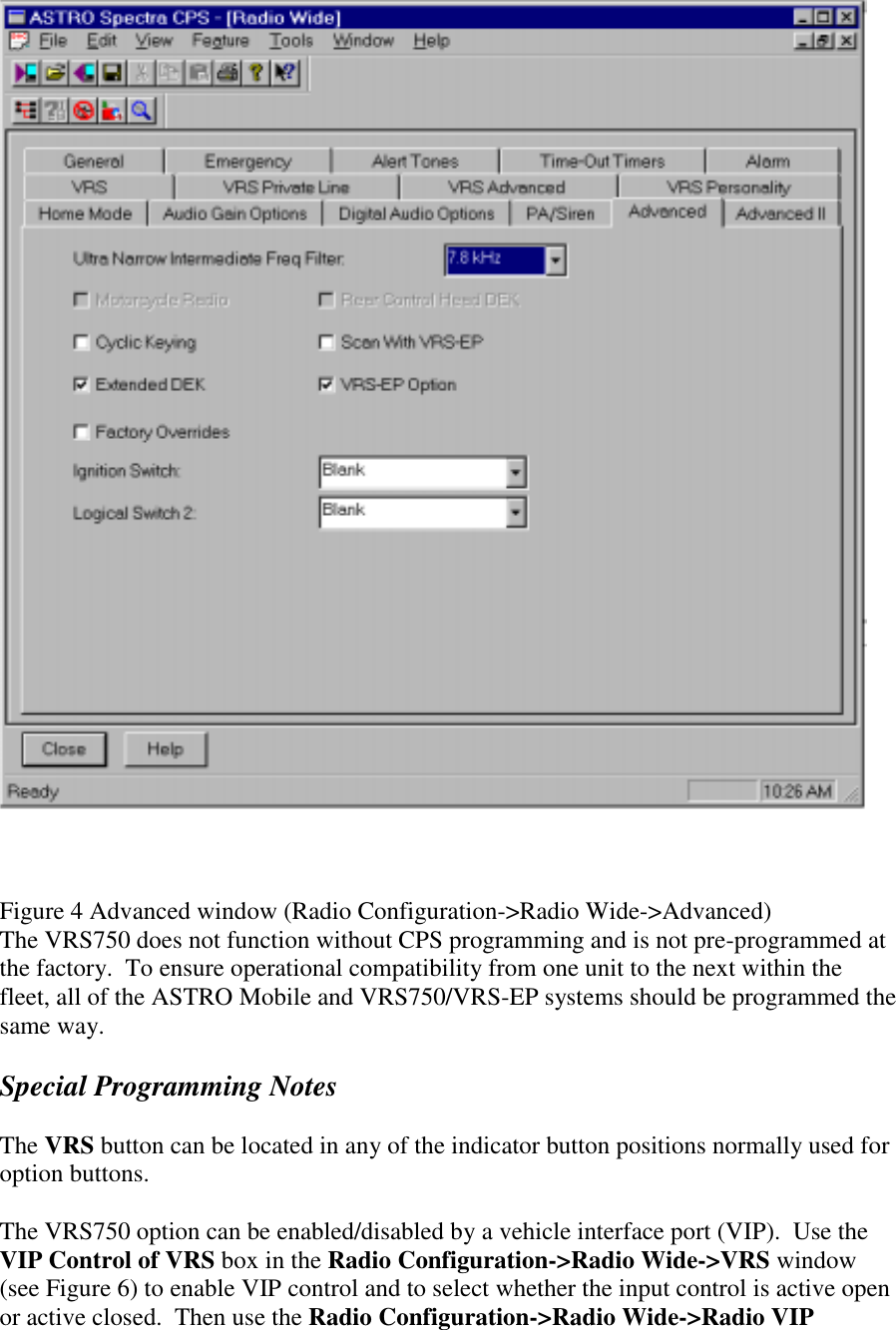
![every 6 seconds is determined by the "temporary message display timer" value. This value (from 250 to 6250 ms [default = 1000 ms]) can be programmed by the CPS. It is in the RADIO WIDE DISPLAY OPTIONS screen (D, C, F from the main CPS screen). Repeater PPI The Repeater Portable Priority Interrupt (PPI), when enabled, causes a base-to-portable transmission to be interrupted every 1 second in trunked mode or 2 seconds in conventional mode so that the repeater can search for a portable radio signal. (These times are programmable and may be changed to 500ms for trunked or 500ms for conventional modes). This interruption may be heard on the portable as a "clicking" noise, but PPI is necessary to give the portable user priority over base-to-portable transmissions, for the self-clearing function of the automatic priority resolution feature, and to allow portable users in trunked mode to break in during system hang time to prevent loss of voice channel. This feature may be disabled through CPS. Quick-Key This feature allows the portable user to determine the status of the mobile trunking system. The feature is initiated by a short press of the portable's PTT that is long enough for the VRS to key the mobile and access the trunking system, for less than 1 second in duration. 4. Installation When selecting the location for the VRS, make certain that there is sufficient clearance for routing the T-cable and the antenna cable to the front of the unit. VRS Installation The standard VRS is installed using the HKN6153A interface cable. The molded DB-25 end connects to the ASTRO front connector. The DB-25 end with the plastic jacket connects to the VRS (see Figure 2). Figure 2 Installing the VRS to an ASTRO Mobile If an external Siren/PA is to be used, the option xxxxAA must be ordered which replaces the HKN6153A cable with a HKN6154A cable, or a separate HKN6154A cable must be ordered. To install, plug the "T" side of the HKN6164A cable to the Siren/PA. Replace the mounting screw on the HKN4363B cable with the double length screw. Plug this side into the "T" cable. Plug the DB-25 end of the HKN6154A into the VRS (see Figure 3). Figure 3 Installing the VRS with an External Siren/PA Mobile Radio Operation and EME Exposure To assure optimal radio performance and that human exposure to radio frequency electromagnetic energy is within guidelines referenced earlier in this document, transmit only when people outside the vehicle are at least the minimum lateral distance away from](https://usermanual.wiki/Motorola-Solutions/92FT4849.Users-Manual/User-Guide-174466-Page-14.png)