Motorola Solutions 92FT4896 Mobile 2-way Radio User Manual 6878215A01
Motorola Solutions, Inc. Mobile 2-way Radio 6878215A01
Contents
- 1. Ex8a RF Safety Booklet
- 2. Ex8b User Manual
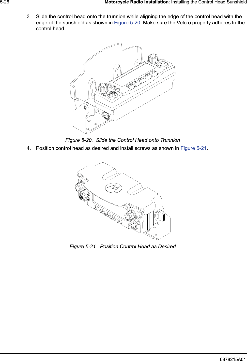
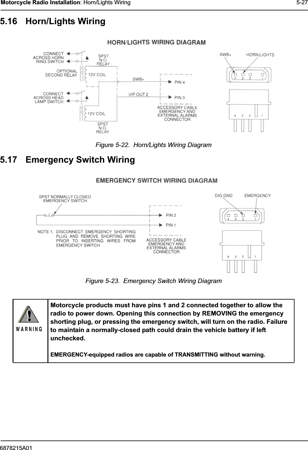
- 3. Ex8c Excerpt from Install Manual
- 4. Ex8b User Manual amended
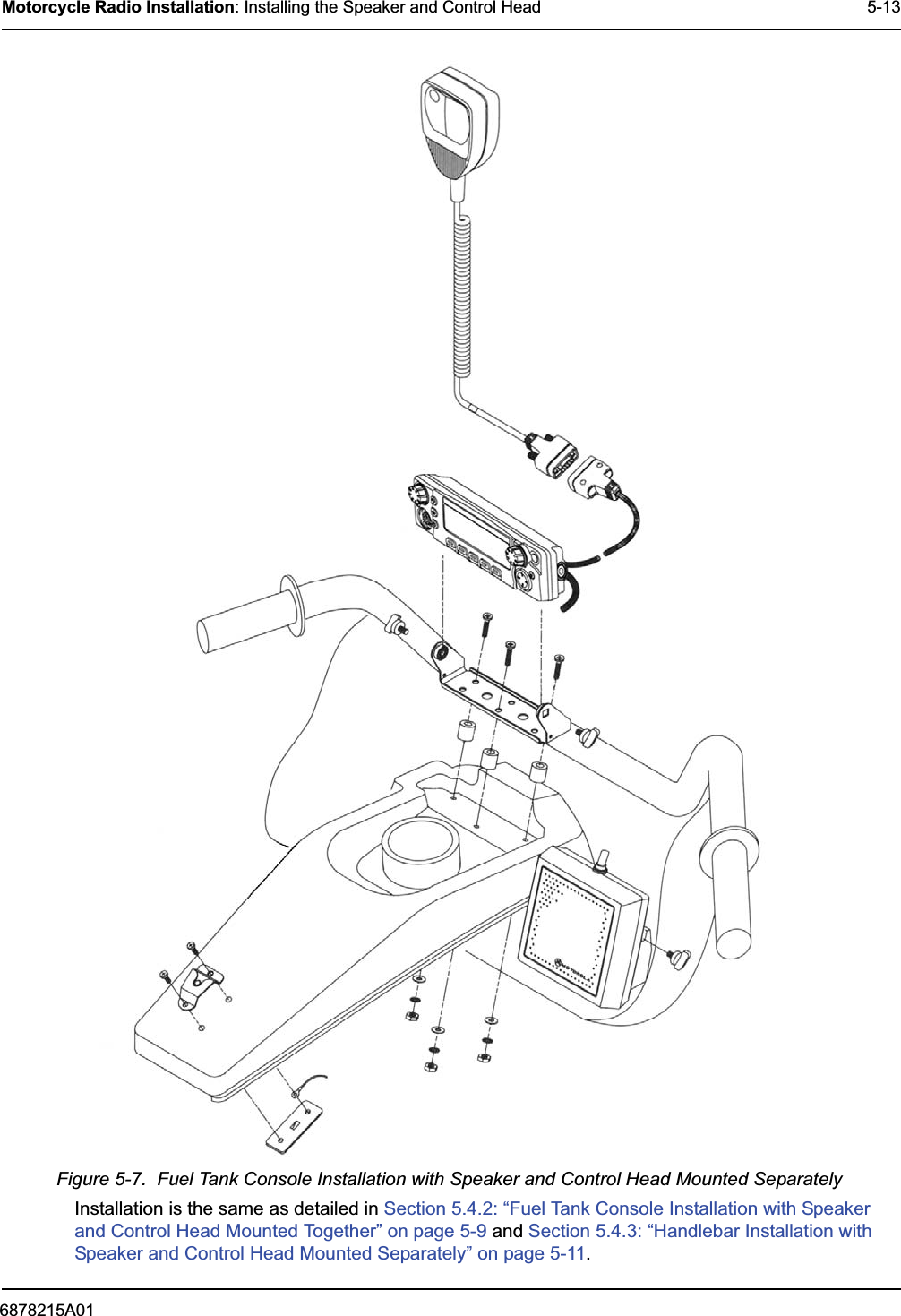
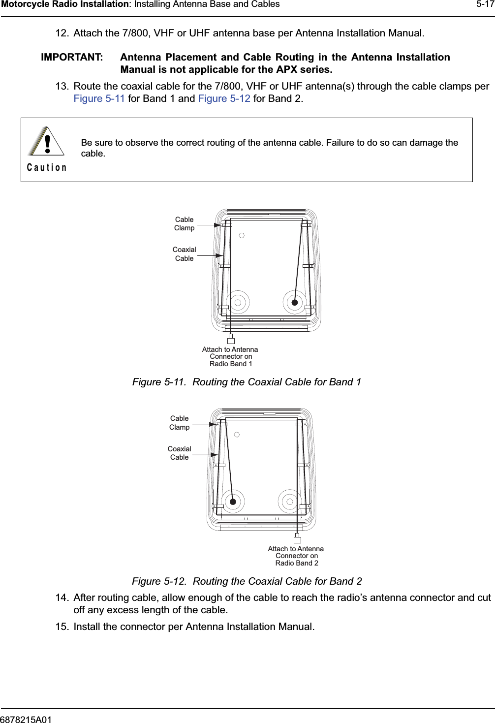
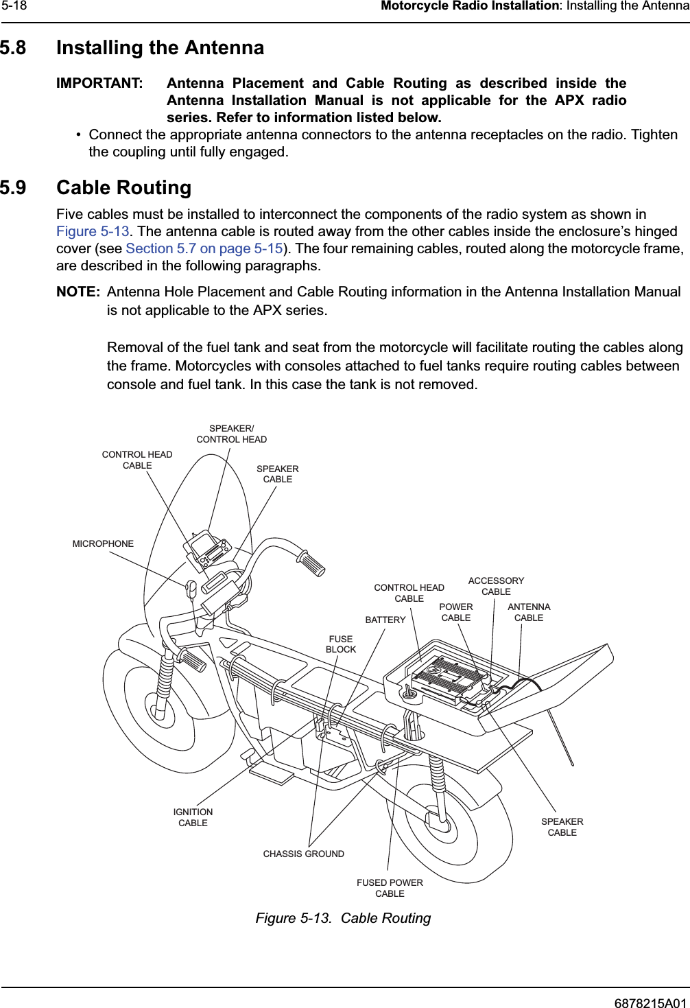
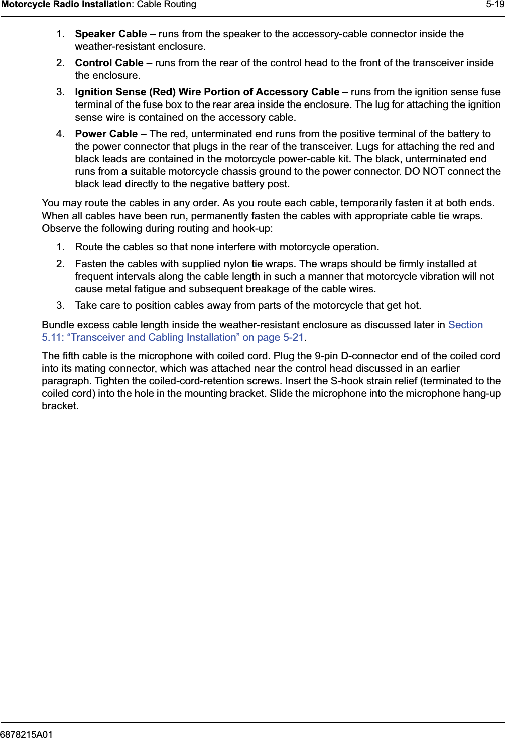
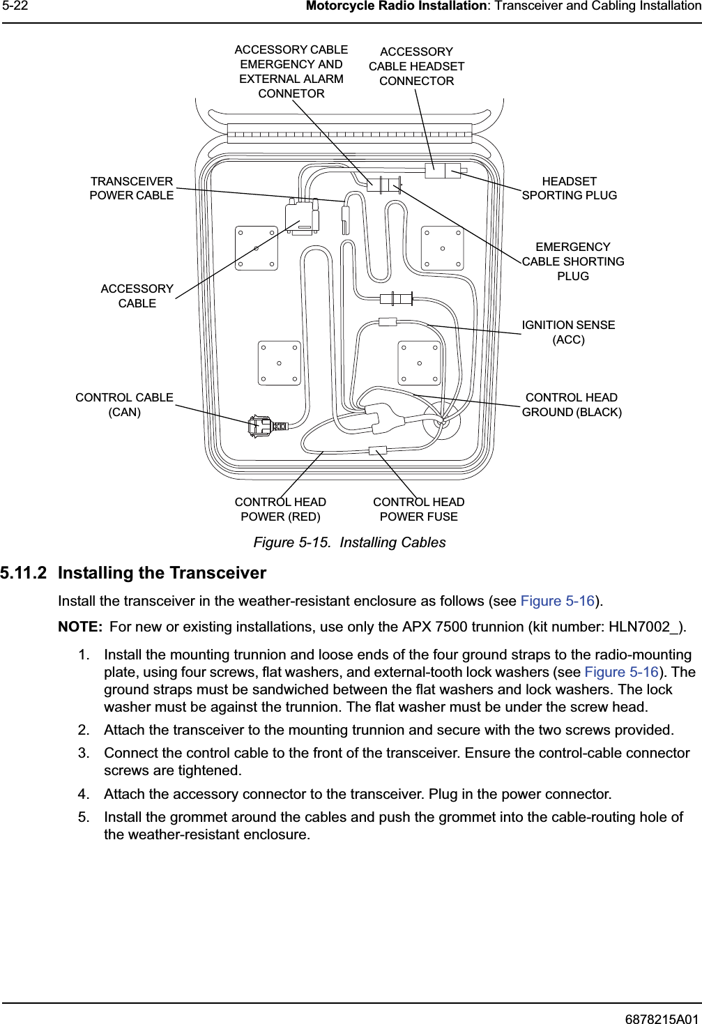
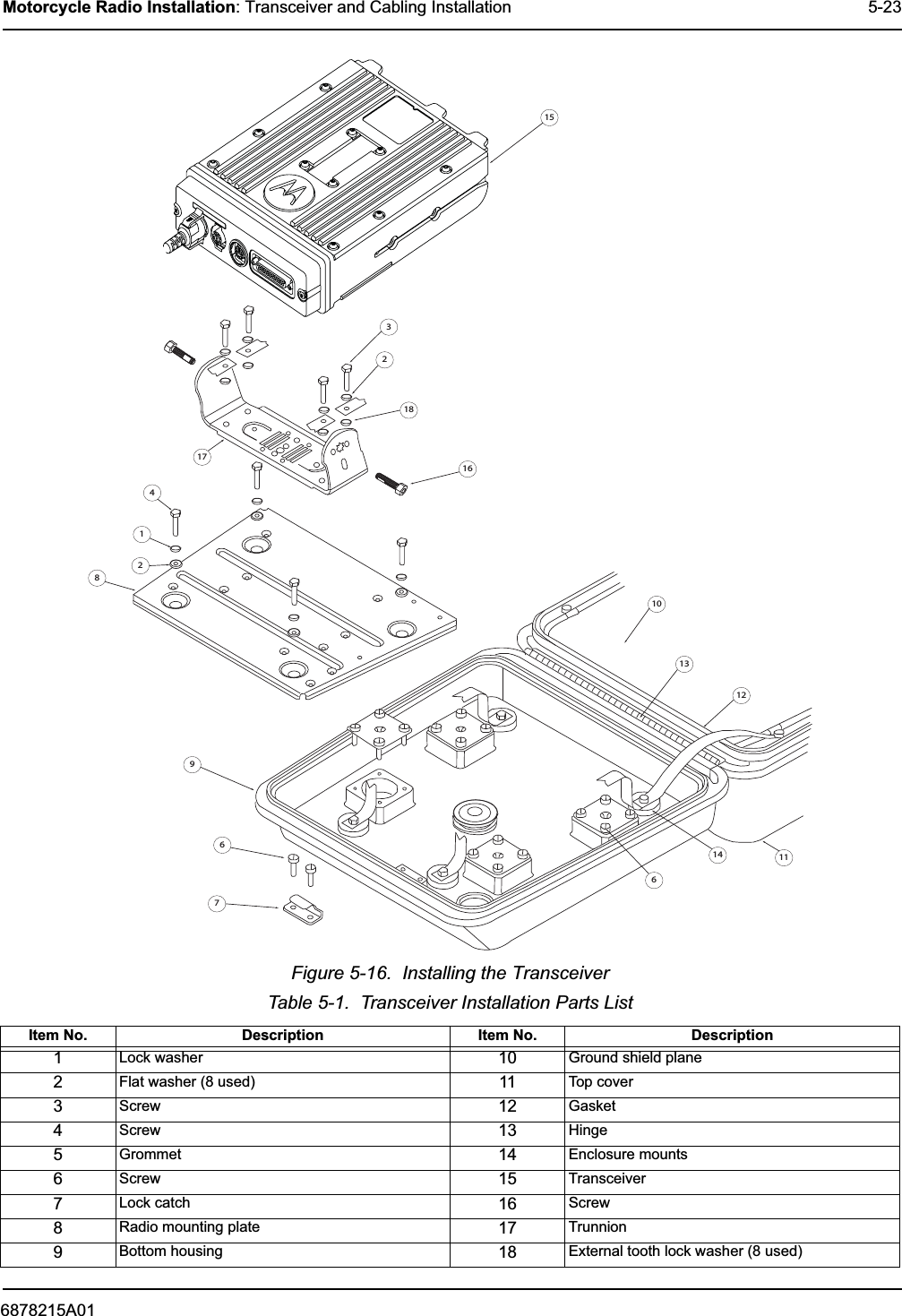
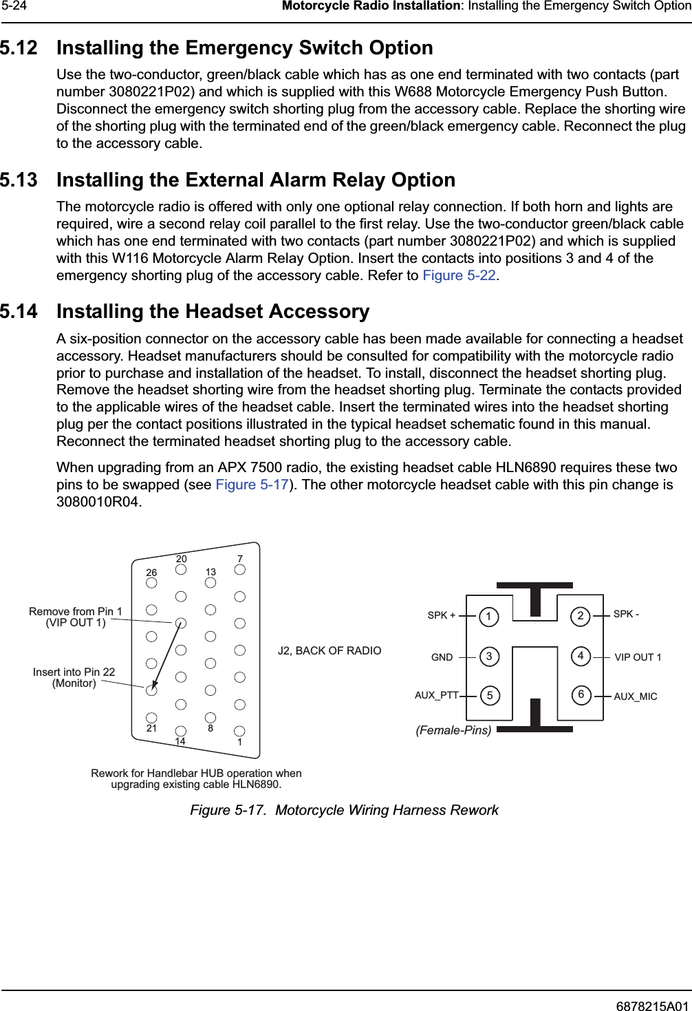
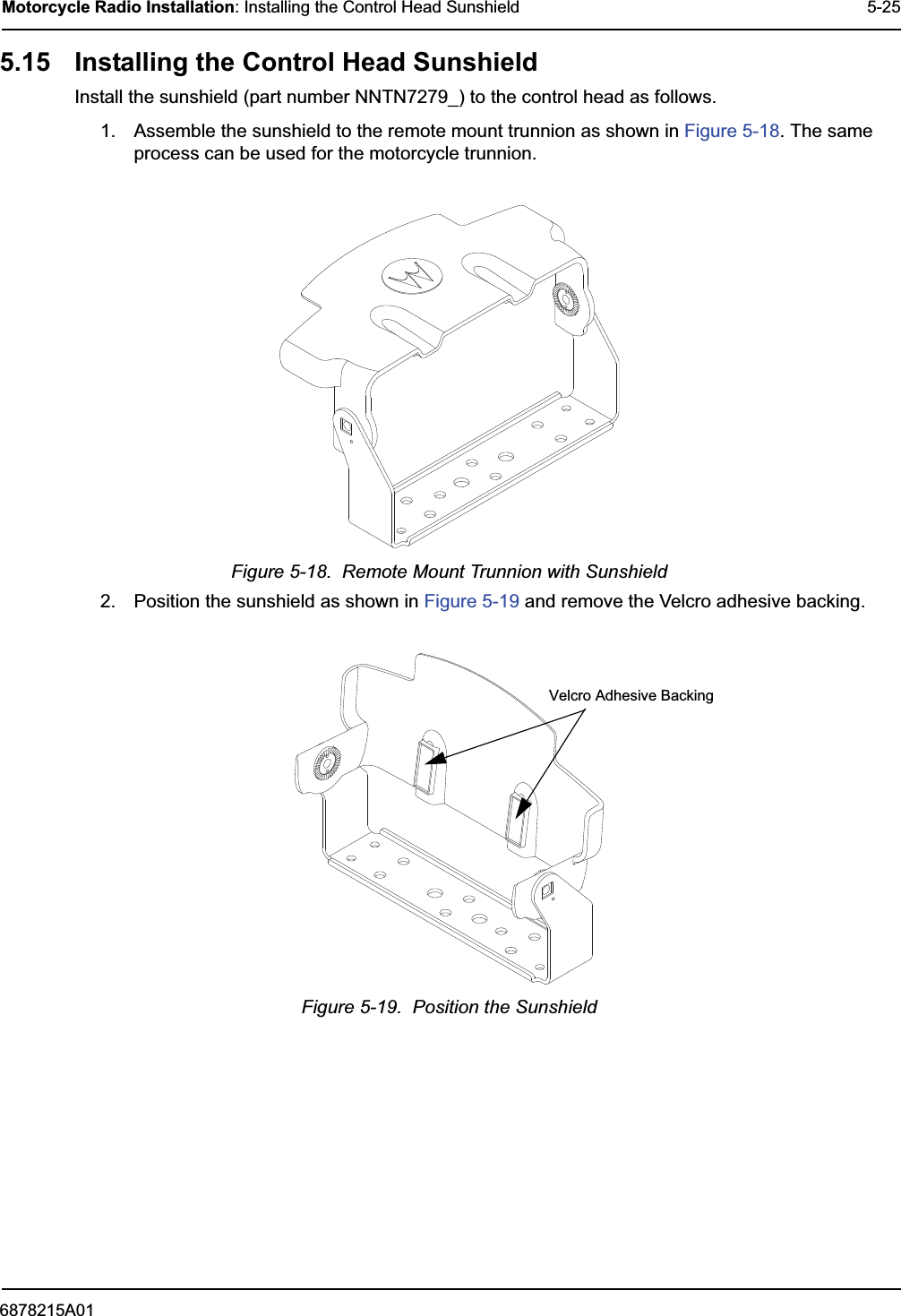
Ex8c Excerpt from Install Manual