Motorola Solutions 92FT4898 Mobile 2-way Radio User Manual APX 7000 Portable Dual Display User Guide
Motorola Solutions, Inc. Mobile 2-way Radio APX 7000 Portable Dual Display User Guide
Contents
- 1. Ex8a Users Manual
- 2. Ex8b RF Safety Booklet
Ex8a Users Manual
APX 7500 User Guide
O9 Control Head
68007024014-A
English
m
ASTRO® APX™ 7500 Series
Digital Mobile Radios
Quick Reference Card
Product Safety and RF Exposure Compliance
ATTENTION!
This radio is restricted to occupational use only to satisfy FCC RF
energy exposure requirements. Before using this product, read
the RF energy awareness information and operating instructions
in the Product Safety and RF Exposure booklet enclosed with
your radio (Motorola Publication part number 6881095C98) to
ensure compliance with RF energy exposure limits.
Radio On/Off
Adjusting Volume
Selecting a Zone
Selecting a Channel
Radio Controls
Receiving and Transmitting
Before using this product, read the operating instructions
for safe usage contained in the Product Safety and RF
Exposure booklet enclosed with your radio.
Press the Power On/Off button to toggle the
power on or off.
Turn the Volume knob clockwise to increase
volume or counterclockwise to decrease the
volume.
1> or < to Zone. Press the Menu Select button
directly under the Zone.
2U or D button until the desired zone is
displayed.
3Press the Menu Select button directly below
Select to confirm the displayed zone.
4Press the PTT button to begin transmitting on
the displayed zone channel.
!
1> or < to Channel. Press the Menu Select
button directly under the Channel.
2U or D button until the desired channel is
displayed.
3Press the Menu Select button directly below
Select to confirm the selected channel.
4Press the PTT button to begin transmitting on
the displayed zone channel.
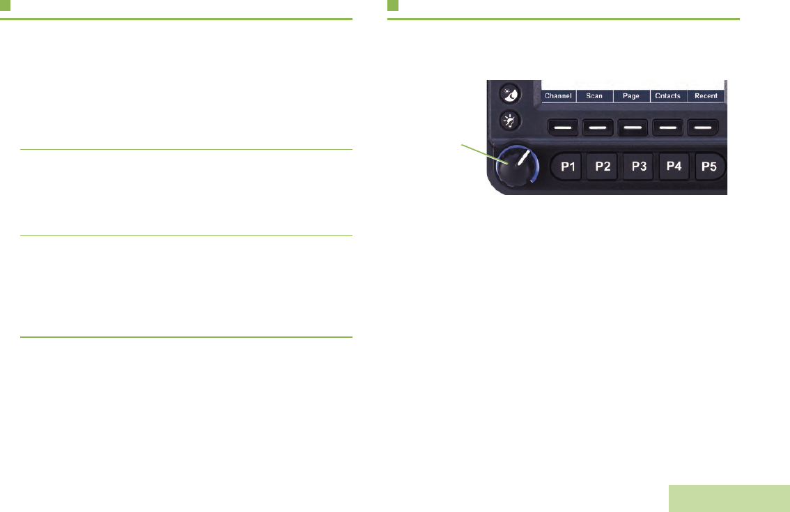
1Turn the Mode Knob to scroll to the required
channel.
2Press PTT button to transmit on the selected
zone channel.
5
4
1
2 3
6
7
8
9
11 101213
14
15
16
17
18
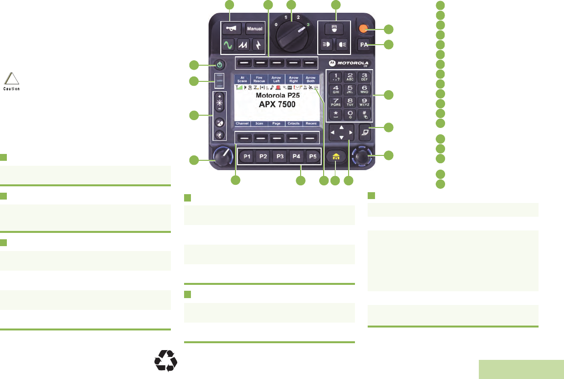
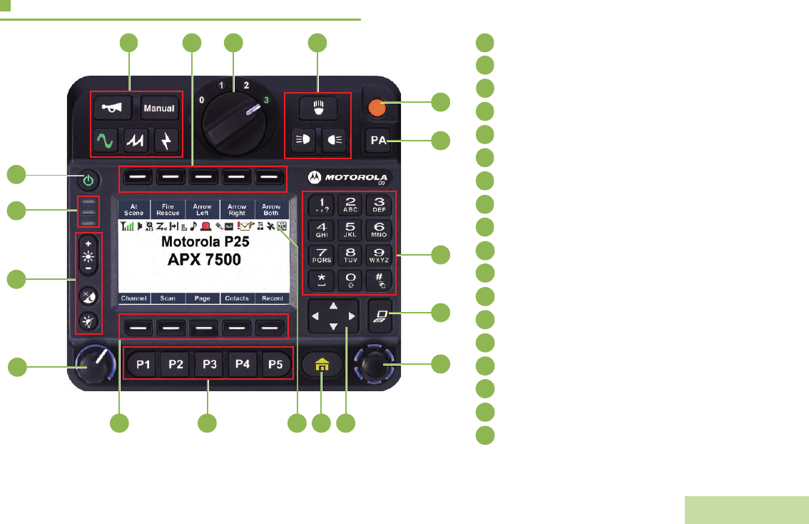
Siren Control Buttons
Programmable Buttons (Top)
Response Selector
Directional Buttons
Orange Button
Public Address Button
Keypad
Data Feature Button
Mode Knob
4-Way Navigation Button
Home Button
Satus Icons
Programmable Buttons
(Bottom)
Menu Select Buttons
Volume Knob
Display Backlight Control
Buttons
LED Indicators
Power On/Off Button
1Take the microphone off hook.
2Select zone/channel.
3Listen for a transmission.
OR
Turn the Volume Knob.
OR
> or < to Monitor then press the Menu Select
button directly below Monitor and listen for
activity.
4Adjust volume, if necessary.
5Press the PTT button to transmit; release to
receive.
1
2
3
4
5
6
7
8
9
10
11
12
13
14
15
16
17
18
*68007024034*
68007024034-A
© 2010 by Motorola, Inc. All Rights Reserved. 05/10
1301 E. Algonquin Rd., Schaumburg,
IL 60196-1078, U.S.A.
English
Sending an Emergency Alarm
To exit emergency at any time, press and hold the
Emergency button.
Sending an Emergency Call (Trunking
Only)
To exit emergency at any time, press and hold the
Emergency button.
Sending a Silent Emergency Alarm
If silent emergency alarm is used with emergency call,
pressing the PTT button exits the silent mode and
initiates the emergency call.
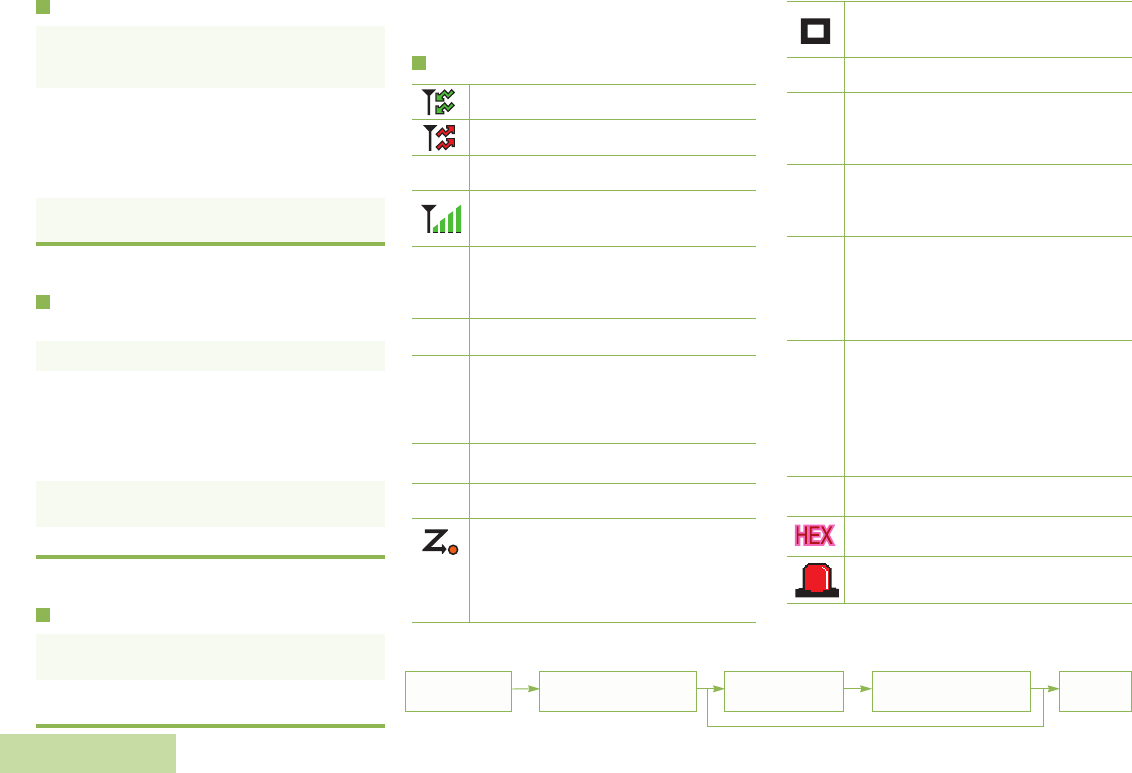
Display Status Icons
1Press the Emergency button. A tone sounds
and the display shows EMERGENCY and the
current zone or channel.
2A dispatcher acknowledgment ACK
RECEIVED display follows.
AND, Trunking Only:
A high-pitched tone indicates that the alarm
has been received by the trunked system’s
central controller.
3Press and hold the emergency button or the
PTT button to return to normal operation.
1Press the Emergency button.
1A tone sounds and the display shows
EMERGENCY and the current zone or channel.
OR
A talk prohibited tone sounds when the
selected channel does not support
emergency.
2Press and hold the PTT button. Speak clearly
into the microphone.
3Release the PTT to end the transmission.
1Press the Emergency button to activate the
silent alarm feature.
2The display does not change; the LED does
not light up, and there is no tone.
Receiving a call or data
Transmitting a call or data
Received an Individual Call.
The more stripes, the stronger the
signal strength for the current site
(trunking only).
Direct radio to radio communication or
connected through a repeater.
On = Direct
Off = Repeater
This channel is being monitored.
Voice muting the affiliated trunking
talkgroup or selected conventional
channel.
On = Enabled
Off = Disabled
L = Radio is set at Low power.
H = Radio is set at High power.
Scanning a scan list.
Blinking dot = Detects activity on the
Priority-One Channel
during scan.
Steady dot = Detects activity on the
Priority-Two Channel
during scan.
F
O
M
K
HOR .
i
Radio is in the view or program mode.
On steady = View mode.
Blinking = Program mode.
The vote scan feature is enabled.
On = Secure operation.
Off = Clear operation.
Blinking = Receiving an encrypted
voice call.
On = AES Secure operation.
Off = Clear operation.
Blinking = Receiving an encrypted
voice call.
On = Location feature enabled, and
location signal available.
Off = Location feature disabled.
Blinking = Location feature enabled,
but location signal
unavailable.
On = User is currently associated with
the radio.
Off = User is currently not associated
with the radio.
Blinking = Device registration or user
registration with the server
failed due to an invalid
username or pin.
Data activity is present.
Indicates that the text entry is currently
in hexadecimal mode.
Alternates between red and blue when
the lightbar is on.
k
m
l
G
n
o
Menu Navigation
< or > to Menu
Entry. - directly below
Menu Entry to select.
U or D to scroll
through sub-list. - directly below
Menu Entry to select. H to exit.

Declaration of Conformity
English
i
Declaration of Conformity
This declaration is applicable to your radio only if your radio is labeled with the FCC logo shown below.
DECLARATION OF CONFORMITY
Per FCC CFR 47 Part 2 Section 2.1077(a)
Responsible Party
Name: Motorola, Inc.
Address: 1301 East Algonquin Road, Schaumburg, IL 60196-1078, U.S.A.
Phone Number: 1-800-927-2744
Hereby declares that the product:
Model Name: APX 7500
conforms to the following regulations:
FCC Part 15, subpart B, section 15.107(a), 15.107(d) and section 15.109(a)
Class B Digital Device
As a personal computer peripheral, this device complies with Part 15 of the FCC Rules. Operation is subject to the
following two conditions:
1. This device may not cause harmful interference, and
2. This device must accept any interference received, including interference that may cause undesired operation.

Declaration of Conformity
English
ii
Note:This equipment has been tested and found to comply with the limits for a Class B digital device, pursuant to part
15 of the FCC Rules. These limits are designed to provide reasonable protection against harmful interference in a
residential installation. This equipment generates, uses and can radiate radio frequency energy and, if not
installed and used in accordance with the instructions, may cause harmful interference to radio communications.
However, there is no guarantee that interference will not occur in a particular installation.
If this equipment does cause harmful interference to radio or television reception, which can be determined by
turning the equipment off and on, the user is encouraged to try to correct the interference by one or more of the
following measures:
• Reorient or relocate the receiving antenna.
• Increase the separation between the equipment and receiver.
• Connect the equipment into an outlet on a circuit different from that to which the receiver is connected.
• Consult the dealer or an experienced radio/TV technician for help.

Contents
English
iii
Contents
This User Guide contains all the information you need
to use the APX™ 7500 Series Digital Mobile Radios.
Declaration of Conformity . . . . . . . . . . . . . . . . . .i
Important Safety Information . . . . . . . . . . . . . .ix
Product Safety and RF Exposure Compliance . . . . .ix
Software Version . . . . . . . . . . . . . . . . . . . . . . . .ix
Computer Software Copyrights . . . . . . . . . . . . x
Documentation Copyrights . . . . . . . . . . . . . . . . x
Disclaimer . . . . . . . . . . . . . . . . . . . . . . . . . . . . . . x
Getting Started . . . . . . . . . . . . . . . . . . . . . . . . . . 1
How to Use This Guide . . . . . . . . . . . . . . . . . . . . . . . 1
Notations Used in This Manual . . . . . . . . . . . . . . . . . 1
Additional Performance Enhancement . . . . . . . . . . . 2
Dynamic System Resilience (DSR) . . . . . . . . . . . . . .2
CrossTalk Prevention . . . . . . . . . . . . . . . . . . . . . . . .2
Encrypted Integrated Data (EID) . . . . . . . . . . . . . . . 2
SecureNet . . . . . . . . . . . . . . . . . . . . . . . . . . . . . . . . 2
What Your Dealer/System Administrator
Can Tell You . . . . . . . . . . . . . . . . . . . . . . . . . . . . . . 3
Preparing Your Radio for Use . . . . . . . . . . . . . .3
Turning On the Radio . . . . . . . . . . . . . . . . . . . . . . . . 4
Validating Compatibility During Power Up . . . . . . . . 5
Adjusting the Volume . . . . . . . . . . . . . . . . . . . . . . . . 5
Adjusting the Display Backlight . . . . . . . . . . . . . . . . . 6
Identifying Radio Controls . . . . . . . . . . . . . . . . .6
Radio Parts and Controls . . . . . . . . . . . . . . . . . . . . 7
Programmable Features . . . . . . . . . . . . . . . . . . . . . . 8
Assignable Radio Functions . . . . . . . . . . . . . . . . . . 8
Assignable Settings or Utility Functions . . . . . . . . . 10
Accessing the Preprogrammed Functions . . . . . . . 10
Using the Menu Select Buttons . . . . . . . . . . . . . . . 10
Using the Navigation Buttons . . . . . . . . . . . . . . . . 11
Home Button . . . . . . . . . . . . . . . . . . . . . . . . . . . . . 11
Data Feature Button . . . . . . . . . . . . . . . . . . . . . . . 11
4-Way Navigation Button . . . . . . . . . . . . . . . . . . . 11
Mode Knob . . . . . . . . . . . . . . . . . . . . . . . . . . . . . . 11
Using the Top Programmable Buttons . . . . . . . . . . 11

Contents
English
iv
Using the Keypad . . . . . . . . . . . . . . . . . . . . . . . . . 12
Keypad Characters – Uppercase Mode . . . . . . . . . 12
Keypad Characters – Lowercase Mode . . . . . . . . . 13
Keypad Characters – Numeric Mode . . . . . . . . . . . 14
Keypad Characters – Hexadecimal Mode . . . . . . . 15
Push-To-Talk (PTT) Button . . . . . . . . . . . . . . . . . . 16
Identifying Status Indicators . . . . . . . . . . . . . .16
Status Icons . . . . . . . . . . . . . . . . . . . . . . . . . . . . . . 17
Text Messaging Service (TMS) Icons . . . . . . . . . . 19
Status Icons . . . . . . . . . . . . . . . . . . . . . . . . . . . . . . 19
TMS Menu Options . . . . . . . . . . . . . . . . . . . . . . . . . 20
Call Type Icons . . . . . . . . . . . . . . . . . . . . . . . . . . . . 21
LED Indicator . . . . . . . . . . . . . . . . . . . . . . . . . . . . . 22
Intelligent Lighting Indicators . . . . . . . . . . . . . . . . . 23
Alert Tones . . . . . . . . . . . . . . . . . . . . . . . . . . . . . . . 24
Phone Call Display and Alert Prompts . . . . . . . . . . 27
General Radio Operation . . . . . . . . . . . . . . . . .28
Selecting a Zone . . . . . . . . . . . . . . . . . . . . . . . . . . 28
Selecting a Radio Channel . . . . . . . . . . . . . . . . . . . 29
Receiving and Responding to a Radio Call . . . . . . 30
Receiving and Responding to a Talkgroup Call . . . 30
Receiving and Responding to a Private Call
(Trunking Only) . . . . . . . . . . . . . . . . . . . . . . . . . . . .31
Receiving and Responding to a Telephone Call
(Trunking Only) . . . . . . . . . . . . . . . . . . . . . . . . . . . .32
Making a Radio Call . . . . . . . . . . . . . . . . . . . . . . . . 33
Making a Talkgroup Call . . . . . . . . . . . . . . . . . . . . .33
Making a Private Call (Trunking Only) . . . . . . . . . . .33
Making an Enhanced Private Call (Trunking
Only) . . . . . . . . . . . . . . . . . . . . . . . . . . . . . . . . . . . .34
Making a Telephone Call (Trunking Only) . . . . . . . .35
Repeater or Direct Operation . . . . . . . . . . . . . . . . . 36
Monitoring Features . . . . . . . . . . . . . . . . . . . . . . . . 36
Monitoring a Channel . . . . . . . . . . . . . . . . . . . . . . .36
Conventional Mode Operation . . . . . . . . . . . . . . . .37
Advanced Features . . . . . . . . . . . . . . . . . . . . . 38
Advanced Call Features . . . . . . . . . . . . . . . . . . . . . 38
Calling a Phone Not in the List . . . . . . . . . . . . . . . .38
Receiving and Making a Selective Call (ASTRO
Conventional Only) . . . . . . . . . . . . . . . . . . . . . . . . .39
Receiving a Selective Call . . . . . . . . . . . . . . . . . . .39
Making a Selective Call . . . . . . . . . . . . . . . . . . . . .39
Using the Talkgroup Call Feature (Conventional
Operation Only) . . . . . . . . . . . . . . . . . . . . . . . . . . . .40
Selecting a Talkgroup . . . . . . . . . . . . . . . . . . . . . . .40
Sending a Status Call . . . . . . . . . . . . . . . . . . . . . . .41

Contents
English
v
Using the Dynamic Regrouping Feature
(Trunking Only) . . . . . . . . . . . . . . . . . . . . . . . . . . . .41
Requesting a Reprogram (Trunking Only) . . . . . . .42
Classifying Regrouped Radios . . . . . . . . . . . . . . . .42
Contacts . . . . . . . . . . . . . . . . . . . . . . . . . . . . . . . . . 43
Making a Private Call from Contacts . . . . . . . . . . . .43
Adding a New Contact Entry . . . . . . . . . . . . . . . . . .44
Deleting a Contact Entry . . . . . . . . . . . . . . . . . . . . .46
Adding a Contact to a Call List . . . . . . . . . . . . . . . .46
Removing a Contact from a Call List . . . . . . . . . . . .47
Editing a Contact in a Call List . . . . . . . . . . . . . . . .47
Editing an Entry Alias . . . . . . . . . . . . . . . . . . . . . . .47
Editing as Entry ID . . . . . . . . . . . . . . . . . . . . . . . . .48
Editing a Call Type . . . . . . . . . . . . . . . . . . . . . . . . .49
Viewing Details of a Contact . . . . . . . . . . . . . . . . . .49
Scan Lists . . . . . . . . . . . . . . . . . . . . . . . . . . . . . . . . 50
Viewing a Scan List . . . . . . . . . . . . . . . . . . . . . . . . .50
Editing the Scan List . . . . . . . . . . . . . . . . . . . . . . . .50
Changing the Scan List Status . . . . . . . . . . . . . . . .51
Viewing and Changing the Priority Status . . . . . . .52
Scan . . . . . . . . . . . . . . . . . . . . . . . . . . . . . . . . . . . . 52
Turning Scan On or Off . . . . . . . . . . . . . . . . . . . . . .52
Transmitting While the Scan is On . . . . . . . . . . . . .53
Radio Programmed for Talkback Scan . . . . . . . . .53
Radio Programmed for Non-Talkback Scan . . . . .53
Making a Dynamic Priority Change (Conventional
Scan Only) . . . . . . . . . . . . . . . . . . . . . . . . . . . . . . . 53
Deleting a Nuisance Channel . . . . . . . . . . . . . . . . 54
Restoring a Nuisance Channel . . . . . . . . . . . . . . . 54
Hang Up (HUB) . . . . . . . . . . . . . . . . . . . . . . . . . . . 55
Call Alert Paging . . . . . . . . . . . . . . . . . . . . . . . . . . . 55
Receiving a Call Alert Page . . . . . . . . . . . . . . . . . . 56
Sending a Call Alert Page . . . . . . . . . . . . . . . . . . . 56
Emergency Operation . . . . . . . . . . . . . . . . . . . . . . . 58
Sending an Emergency Alarm . . . . . . . . . . . . . . . . 58
Sending an Emergency Call (Trunking Only) . . . . 59
Sending an Emergency Alarm with Emergency
Call . . . . . . . . . . . . . . . . . . . . . . . . . . . . . . . . . . . . . 59
Sending a Silent Emergency Alarm . . . . . . . . . . . . 60
Using the Emergency Keep-Alive Feature . . . . . . . 61
Automatic Registration Service (ARS) . . . . . . . . . . 62
Viewing the Channel which supports ARS Mode . 62
Accessing the User Login Feature . . . . . . . . . . . . . 62
Logging In as a User . . . . . . . . . . . . . . . . . . . . . . . 63
Logging Out . . . . . . . . . . . . . . . . . . . . . . . . . . . . . 64
Text Messaging Service (TMS) . . . . . . . . . . . . . . . . 64
Accessing the TMS Features . . . . . . . . . . . . . . . . . 65
Composing and Sending a New Text Message . . . 65
Sending a Quick Text Message . . . . . . . . . . . . . . . 67
Using the Priority Status and Request Reply
Features . . . . . . . . . . . . . . . . . . . . . . . . . . . . . . . . . 68

Contents
English
vi
Appending a Priority Status to a Text Message . . . 68
Removing a Priority Status from a Text Message . 69
Appending a Request Reply to a Text Message . . 69
Removing a Request Reply from a Text
Message . . . . . . . . . . . . . . . . . . . . . . . . . . . . . . . . 69
Appending a Priority Status and a Reply Request
to a Text Message . . . . . . . . . . . . . . . . . . . . . . . . . 69
Removing a Priority Status and a Reply Request
from a Text Message . . . . . . . . . . . . . . . . . . . . . . . 70
Managing Text Messages . . . . . . . . . . . . . . . . . . . 70
Receiving a Text Message . . . . . . . . . . . . . . . . . . 70
Viewing a Text Message from the Inbox . . . . . . . . 71
Replying to a Received Text Message . . . . . . . . . 71
Accessing the Drafts Folder . . . . . . . . . . . . . . . . . . 72
Managing Sent Text Messages . . . . . . . . . . . . . . . 73
Viewing a Sent Text Message . . . . . . . . . . . . . . . . 73
Sending a Sent Text Message . . . . . . . . . . . . . . . 74
Deleting a Text Message . . . . . . . . . . . . . . . . . . . . 74
Deleting All Text Messages . . . . . . . . . . . . . . . . . . 75
Secure Operations . . . . . . . . . . . . . . . . . . . . . . . . . 76
Enabling the Secure Transmission . . . . . . . . . . . . . 76
Managing Encryption . . . . . . . . . . . . . . . . . . . . . . . 76
Loading the Encryption Key(s) . . . . . . . . . . . . . . . 76
Using the Multikey Feature . . . . . . . . . . . . . . . . . . 77
Selecting an Encryption Key . . . . . . . . . . . . . . . . . 77
Selecting a Keyset . . . . . . . . . . . . . . . . . . . . . . . . . 78
Erasing the Selected Encryption Keys . . . . . . . . . . 78
Requesting an Over-the-Air Rekey (ASTRO
Conventional Only) . . . . . . . . . . . . . . . . . . . . . . . . .79
MDC Over-the-Air Rekeying (OTAR) Page . . . . . .79
Hear Clear . . . . . . . . . . . . . . . . . . . . . . . . . . . . . . .80
Security . . . . . . . . . . . . . . . . . . . . . . . . . . . . . . . . . 80
Using the Radio Lock . . . . . . . . . . . . . . . . . . . . . . .80
Unlocking Your Radio . . . . . . . . . . . . . . . . . . . . . . .80
Changing Your Password . . . . . . . . . . . . . . . . . . . .81
Enabling or Disabling the Radio Lock Feature
(Secure Radios Only) . . . . . . . . . . . . . . . . . . . . . . .82
The Global Positioning System (GPS) . . . . . . . . . . 82
Understanding the GPS Feature . . . . . . . . . . . . . . .82
Enhancing GPS Performance . . . . . . . . . . . . . . . . .83
Using the Outdoor Location Feature (Using GPS) .83
Accessing the Outdoor Location Feature . . . . . . . .84
Saving a Waypoint . . . . . . . . . . . . . . . . . . . . . . . . .85
Viewing a Saved Waypoint . . . . . . . . . . . . . . . . . . .86
Editing the Alias of a Waypoint . . . . . . . . . . . . . . . .86
Editing the Coordinates of a Waypoint . . . . . . . . . .87
Deleting a Single Saved Waypoint . . . . . . . . . . . . .88
Deleting All Saved Waypoints . . . . . . . . . . . . . . . .89
Measuring the Distance and Bearing from a
Saved Waypoint . . . . . . . . . . . . . . . . . . . . . . . . . . .89
Using the Location Feature While in Emergency
Mode . . . . . . . . . . . . . . . . . . . . . . . . . . . . . . . . . . .90
Trunking System Controls . . . . . . . . . . . . . . . . . . . 90
Using the Failsoft System . . . . . . . . . . . . . . . . . . . .90

Contents
English
vii
Going Out of Range . . . . . . . . . . . . . . . . . . . . . . . .91
SmartZone™ . . . . . . . . . . . . . . . . . . . . . . . . . . . . . .91
Using the Site Trunking Feature . . . . . . . . . . . . . . .91
Locking and Unlocking a Site . . . . . . . . . . . . . . . . .92
Viewing and Changing a Site . . . . . . . . . . . . . . . . .92
Viewing the Current Site . . . . . . . . . . . . . . . . . . . .92
Changing the Current Site . . . . . . . . . . . . . . . . . . .92
Using the Trunked Announcement . . . . . . . . . . . . .93
Initiating an Announcement . . . . . . . . . . . . . . . . . .93
Utilities . . . . . . . . . . . . . . . . . . . . . . . . . . . . . . . . . . 94
Viewing the Recent Calls List . . . . . . . . . . . . . . . . .94
Selecting the Power Level . . . . . . . . . . . . . . . . . . . .95
Selecting a Radio Profile . . . . . . . . . . . . . . . . . . . . .95
Toggling the Day or Night Display Mode . . . . . . . . .96
Selecting the Stealth Mode . . . . . . . . . . . . . . . . . . .96
Turning Keypad Tones On or Off . . . . . . . . . . . . . .96
Turning Voice Mute On or Off . . . . . . . . . . . . . . . . .97
Using the Time-Out Timer . . . . . . . . . . . . . . . . . . . .97
Using the Conventional Squelch Operation
Features . . . . . . . . . . . . . . . . . . . . . . . . . . . . . . . . .98
Analog Options . . . . . . . . . . . . . . . . . . . . . . . . . . .98
Digital Options . . . . . . . . . . . . . . . . . . . . . . . . . . . .98
Using the PL Defeat Feature . . . . . . . . . . . . . . . . . .98
Using the Digital PTT ID Feature . . . . . . . . . . . . . .99
Using the Smart PTT Feature
(Conventional Only) . . . . . . . . . . . . . . . . . . . . . . . .99
Using Quick-Key Override . . . . . . . . . . . . . . . . . 100
Accessing the General Radio Information . . . . . . 100
Accessing the Radio Information . . . . . . . . . . . . 100
Viewing the IP Information . . . . . . . . . . . . . . . . . 101
Viewing the Control Assignments . . . . . . . . . . . . 102
Using the Directional Buttons . . . . . . . . . . . . . . . 102
Using the Siren Control Keyapad . . . . . . . . . . . . 103
Using the Manual Siren Button for Manual Siren
Tone . . . . . . . . . . . . . . . . . . . . . . . . . . . . . . . . . . . 103
Using the Manual Siren Button as Siren Types
Selector . . . . . . . . . . . . . . . . . . . . . . . . . . . . . . . . 104
Using the Public Address Button . . . . . . . . . . . . . 104
Using the Response Selector . . . . . . . . . . . . . . . 104
Using External Alarms (Horn and Lights) . . . . . . 105
Using Non-Permanent Horn and Lights . . . . . . . 105
Using Permanent Horn and Lights . . . . . . . . . . . 106
Changing the Selected Alarms . . . . . . . . . . . . . . 106
Using the Gun Lock . . . . . . . . . . . . . . . . . . . . . . . 106
Unlocking Single Gun Lock . . . . . . . . . . . . . . . . . 106
Unlocking All Gun Locks . . . . . . . . . . . . . . . . . . . 107
Using the Voice Announcement . . . . . . . . . . . . . 107
Using the Action Consolidation Mode . . . . . . . . . 109
Activating the Action Consolidation Activities . . . 109
Deactivating the Action Consolidation Activities . 110
Helpful Tips . . . . . . . . . . . . . . . . . . . . . . . . . . .111
Caring for Your Radio . . . . . . . . . . . . . . . . . . . . . . 111

Contents
English
viii
Accessories . . . . . . . . . . . . . . . . . . . . . . . . . . .112
Antennas . . . . . . . . . . . . . . . . . . . . . . . . . . . . . . . 112
Audio . . . . . . . . . . . . . . . . . . . . . . . . . . . . . . . . . . 113
Control Station . . . . . . . . . . . . . . . . . . . . . . . . . . . 114
Footswitches and PTTs . . . . . . . . . . . . . . . . . . . . 114
Direct Entry Keypad, Siren and URC . . . . . . . . . . 115
Microphones . . . . . . . . . . . . . . . . . . . . . . . . . . . . . 115
Motorcycle . . . . . . . . . . . . . . . . . . . . . . . . . . . . . . 116
Mounting Solution . . . . . . . . . . . . . . . . . . . . . . . . . 116
Power/CAN Cables . . . . . . . . . . . . . . . . . . . . . . . 116
Programming/Accessory Cables . . . . . . . . . . . . . 117
Siren / Direct Entry Keypad . . . . . . . . . . . . . . . . . 118
Appendix: Maritime Radio Use in the VHF
Frequency Range . . . . . . . . . . . . . . . . . . . . . 119
Special Channel Assignments . . . . . . . . . . . . . . . 119
Emergency Channel . . . . . . . . . . . . . . . . . . . . . . .119
Non-Commercial Call Channel . . . . . . . . . . . . . . .119
Operating Frequency Requirements . . . . . . . . . . 120
Glossary . . . . . . . . . . . . . . . . . . . . . . . . . . . . . 122
Commercial Warranty . . . . . . . . . . . . . . . . . . 127
Notes . . . . . . . . . . . . . . . . . . . . . . . . . . . . . . . . 130

Important Safety Information
English
ix
Important Safety Information
Product Safety and RF Exposure Compliance
ATTENTION!
This radio is restricted to occupational use only to
satisfy FCC RF energy exposure requirements.
Before using this product, read the RF energy awareness
information and operating instructions in the Product
Safety and RF Exposure booklet enclosed with your radio
(Motorola Publication part number 6881095C98) to
ensure compliance with RF energy exposure limits.
For a list of Motorola-approved antennas, batteries, and
other accessories, visit the following website:
http://www.motorola.com/governmentandenterprise
Software Version
All the features described in the following sections are
supported by the radio's software version R04.00.00 or
later.
See Accessing the Radio Information on page 100 to
determine your radio's software version.
Check with your dealer or system administrator
for more details of all the features supported.
Before using this product, read the operating
instructions for safe usage contained in the
Product Safety and RF Exposure booklet
enclosed with your radio.
!

Computer Software Copyrights
English
x
Computer Software Copyrights
The Motorola products described in this manual may
include copyrighted Motorola computer programs stored
in semiconductor memories or other media. Laws in the
United States and other countries preserve for Motorola
certain exclusive rights for copyrighted computer
programs, including, but not limited to, the exclusive right
to copy or reproduce in any form the copyrighted
computer program. Accordingly, any copyrighted
Motorola computer programs contained in the Motorola
products described in this manual may not be copied,
reproduced, modified, reverse-engineered, or distributed
in any manner without the express written permission of
Motorola. Furthermore, the purchase of Motorola
products shall not be deemed to grant either directly or by
implication, estoppel, or otherwise, any license under the
copyrights, patents or patent applications of Motorola,
except for the normal non-exclusive license to use that
arises by operation of law in the sale of a product.
Documentation Copyrights
No duplication or distribution of this document or any
portion thereof shall take place without the express
written permission of Motorola. No part of this manual
may be reproduced, distributed, or transmitted in any
form or by any means, electronic or mechanical, for any
purpose without the express written permission of
Motorola.
Disclaimer
The information in this document is carefully examined,
and is believed to be entirely reliable. However, no
responsibility is assumed for inaccuracies. Furthermore,
Motorola reserves the right to make changes to any
products herein to improve readability, function, or
design. Motorola does not assume any liability arising out
of the applications or use of any product or circuit
described herein; nor does it cover any license under its
patent rights, nor the rights of others.
Getting Started
English
1
Getting Started
Take a moment to review the following:
How to Use This Guide . . . . . . . . . . . . . . . . . . . . . . . . . page 1
Notations Used in This Manual . . . . . . . . . . . . . . . . . . . page 1
Additional Performance Enhancement . . . . . . . . . . . . . page 2
What Your Dealer/System Administrator
Can Tell You. . . . . . . . . . . . . . . . . . . . . . . . . . . . . . . . page 3
How to Use This Guide
This User Guide covers the basic operation of the APX™ 7500
O9 Control Head Mobile Radios.
However, your dealer or system administrator may have
customized your radio for your specific needs. Check with your
dealer or system administrator for more information.
Notations Used in This Manual
Throughout the text in this publication, you will notice the use of
WARNING, Caution, and Note. These notations are used to
emphasize that safety hazards exist, and the care that must be
taken or observed.
An operational procedure, practice, or condition,
etc., which may result in injury or death if not
carefully observed.
An operational procedure, practice, or
condition, etc., which may result in damage
to the equipment if not carefully observed.
Note: An operational procedure, practice, or condition,
etc., which is essential to emphasize.
!!
!

Getting Started
English
2
The following special notations identify certain items:
Additional Performance Enhancement
The following are some of the latest creations designed to
enhance the security, quality and efficiency of APX radios.
Dynamic System Resilience (DSR)
DSR ensures the radio system is seamlessly switched to a
backup master site dynamically in case of system failure.
DSR also provides additional indication e.g. failure detection,
fault recovery, and redundancy within the system to address to
the user in need. Mechanisms related to the Integrated Voice
and Data (IV & D) or data centric are all supported by DSR.
CrossTalk Prevention
This feature prevents crosstalk scenario from happening,
especially when a wideband antenna is used. This feature
allows the adjustment of the Trident Transmitting SSI clock rate
in the radio to be varied from the Receiving Frequency. This
subsequently reduced the possibilities of radio frequency
interfering spurs and prevents the issues of crosstalk.
Encrypted Integrated Data (EID)
EID provides security encryption and authentication of IV & D
data bearer service communication between the radio and the
Customer Enterprise Network.
SecureNet
SecureNet allows user to perform secured communications on
an Analog or Motorola Data Communication (MDC) channel.
The MDC OTAR feature will allow users to perform OTAR
activities on an MDC channel.
Example Description
Home button
or H
Buttons and keys are shown in bold print
or as an icon.
Phone Menu entries are shown similar to the
way they appear on the radio’s display.
>This means “Press the right side of the
4-way Navigation button.”

Preparing Your Radio for Use
English
3
What Your Dealer/System Administrator
Can Tell You
Check with your dealer or system administrator, if the radio is to
be operated in extremely cold temperatures (less than -20 °C),
for the correct radio settings to ensure proper operation.
You can also consult your dealer or system administrator about
the following:
•Is your radio preprogrammed with any preset conventional
channels?
•Which buttons have been preprogrammed to access other
features?
•What optional accessories may suit your needs?
Preparing Your Radio for Use
Assemble your radio by following these steps:
Turning On the Radio. . . . . . . . . . . . . . . . . . . . . . . . . . .page 4
Validating Compatibility During Power Up . . . . . . . . . . .page 5
Adjusting the Volume . . . . . . . . . . . . . . . . . . . . . . . . . . .page 5
Adjusting the Display Backlight . . . . . . . . . . . . . . . . . . .page 6
Preparing Your Radio for Use
English
4
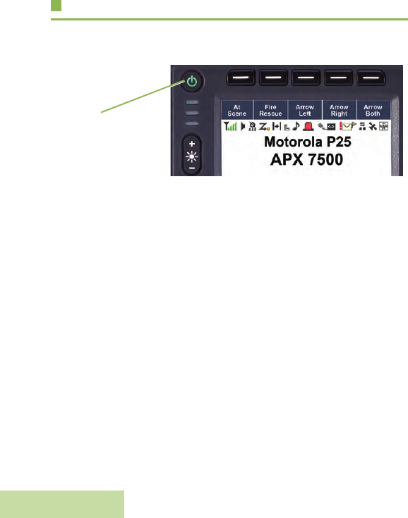
Turning On the Radio
Press the Power On/Off Button briefly to power on the radio.
After a short time, the red, yellow and green LEDs light up. The
display then shows Zone and channel text, and menu items
display on the screen.
The backlight will turn on to the last selected dim level.
Note: Pressing the Power On/Off Button before the LED
lights up will be ignored.
If Fail ##/## appears in the display, the radio will not
function until the condition has been corrected.
If Error ##/## appears, some non-critical data has
been changed. If either of these displays appear, if the
display goes blank, or if the unit appears to be locked
up, see Helpful Tips on page 99 for more information.
If Ch mismatch appears, means that either the Control
Head has been connected to an incompatible
transceiver, or vice versa.
If your radio does not power up, contact your dealer.
To turn off the radio, press the Power On/Off Button after the
LEDs light up.
Power On/Off button
Preparing Your Radio for Use
English
5
Validating Compatibility During Power Up
The radio validates and updates the software and hardware of
your control head(s) during power up. Follow the procedure
below when your radio runs this task.
Procedure:
1The display shows Maintenance Mode Remote Device
promptly followed by other maintenance statuses.
2The display shows Update done Please reset upon
completion.
OR
The display shows Update failed Please reset when it
fails to update.
3Press the Power On/Off Button to reset. The radio runs the
usual power up operation if the software updates are
complete.
OR
The radio runs the Maintenance Mode if the updates are not
complete and repeat step 1.
Note: If SW incomplete appears, use Flashport Recovery
Tool to update the control heads before you power on
the radio again.
Adjusting the Volume
To increase the volume, rotate the Volume Knob clockwise.
To decrease the volume, rotate the Volume Knob
counterclockwise.
Volume Knob

Identifying Radio Controls
English
6
Adjusting the Display Backlight
You can change the intensity of the radio’s display backlight as
needed to suite the environment conditions.
Note: The backlight setting also affects the Menu Select
buttons, the Menu Navigation buttons and the keypad
backlighting accordingly.
Procedure:
Press and hold + on the n button to increase brightness.
Release the button to stop.
OR
Press and hold the - on the n button to decrease brightness.
Release the button to stop.
Identifying Radio Controls
Take a moment to review the following:
Radio Parts and Controls. . . . . . . . . . . . . . . . . . . . . . . . page 7
Programmable Features . . . . . . . . . . . . . . . . . . . . . . . . page 8
Assignable Radio Functions. . . . . . . . . . . . . . . . . . . . page 8
Assignable Settings or Utility Functions . . . . . . . . . . page 10
Accessing the Preprogrammed Functions. . . . . . . . . . page 10
Using the Menu Select Buttons . . . . . . . . . . . . . . . . page 10
Using the Navigation Buttons. . . . . . . . . . . . . . . . . . page 11
Using the Keypad . . . . . . . . . . . . . . . . . . . . . . . . . . . . page 12
Keypad Characters – Uppercase Mode . . . . . . . . . . page 12
Keypad Characters – Lowercase Mode . . . . . . . . . . page 13
Keypad Characters – Numeric Mode . . . . . . . . . . . . page 14
Keypad Characters – Hexadecimal Mode . . . . . . . . page 15
Push-To-Talk (PTT) Button . . . . . . . . . . . . . . . . . . . . . page 16
Identifying Radio Controls
English
7
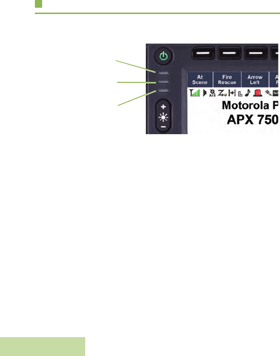
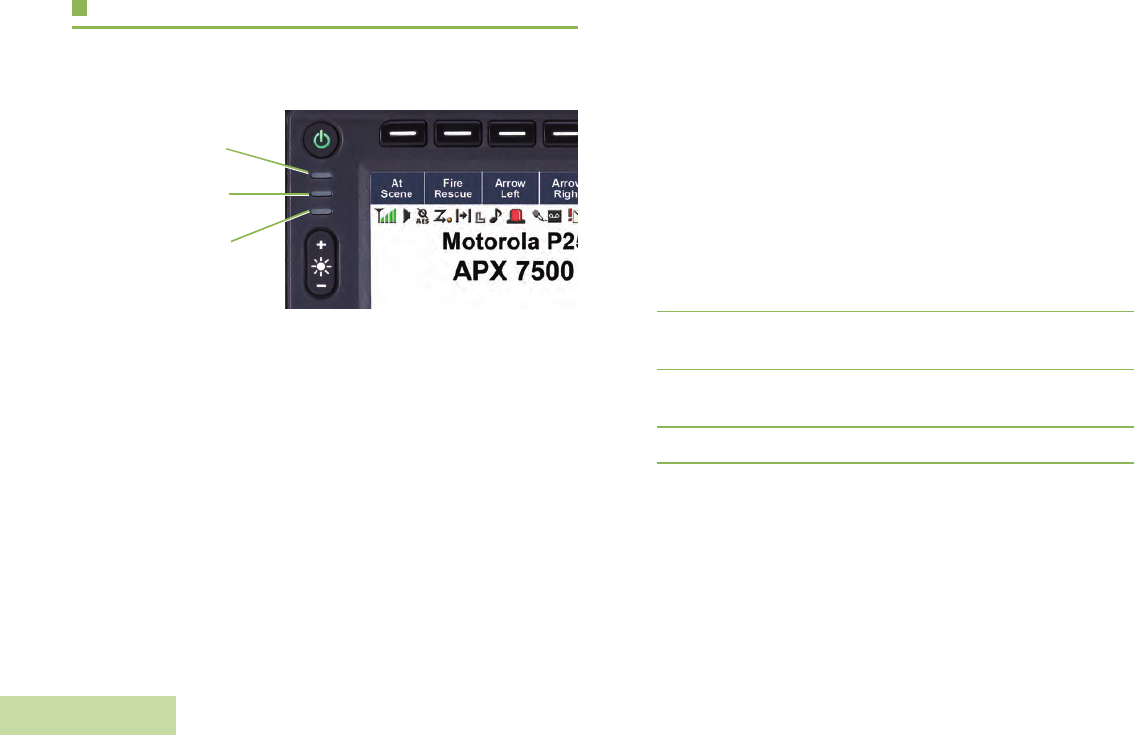
Radio Parts and Controls
43
8
11
16
17
18
Siren Control Buttons
Programmable Buttons (Top)
Response Selector
Directional Buttons
Orange Button
Public Address Button
Keypad
Data Feature Button
Mode Knob
4-Way Navigation Button
Home Button
Satus Icons
Programmable Buttons (Bottom)
Menu Select Buttons
Volume Knob
Display Backlight Control Buttons
LED Indicators
Power On/Off Button
1
2
3
4
5
6
7
8
9
10
11
12
13
14
15
16
17
18
13
2
1
5
6
7
9
1014
15
12

Identifying Radio Controls
English
8
Programmable Features
Any reference in this manual to a control that is
“preprogrammed” means that the control must be programmed
by a dealer or qualified radio technician using the radio's
programming software, in order to assign a feature to that
control.
The programmable buttons can be programmed as shortcuts to
radio functions or preset channels/groups depending on the
duration of a button press:
•Press – Pressing and releasing rapidly.
•Long press – Pressing and holding for the preprogrammed
duration (between 0.25 seconds and 3.75 seconds).
•Hold down – Keeping the button pressed.
Assignable Radio Functions
Action Consolidation – Allows the radio to execute a specific
sequence of actions that combine audio, visual and location
data. E.g. Mode Change, Lightbar, Siren, Direct Status and
Location Data.
Call Alert – Allows the radio to function like a pager, or to verify
if a radio is active on the system.
Call Response – Allows you to answer a private call.
Channel – Selects a channel.
Contacts – Selects the Contacts menu.
Dynamic Priority (Conventional Only) – Allows any channel
in a scan list (except for the Priority-One channel) to temporarily
replace the Priority-Two channel.
Emergency – Depending on the programming, initiates or
cancels an emergency alarm or call.
Gun Lock – Triggers the Gun Lock(s) to open.
Information – Displays the information of the radio.
Internet Protocol Address – Displays the Internet Protocol (IP)
address, device name and status of the radio.
Location – Determines the current location (latitude, longitude,
time and date), and also the distance and bearing to another
location. Or, turns the GPS functionality on or off for all location.
Message – Enters the current message list.
Monitor (Conventional Only) – Monitors a selected channel
for all radio traffic until function is disabled.
Multiple Private Line (Conventional Only) – Selects the
Multiple Private Line lists.
Nuisance Delete – Temporarily removes an unwanted channel,
except for priority channels or the designated transmit channel,
from the scan list.

Identifying Radio Controls
English
9
One Touch 1 – 4 – Launches a specific feature with one single
button-press. You can setup as much as four separately
programmed buttons for four different features.
Phone – Allows you to make and receive calls similar to
standard phone calls.
Private Call (Trunking Only) – Allows a call from an individual
radio to another individual radio.
Radio Profiles – Allows for easy access to a set of
preprogrammed visual and audio settings of the radio.
Recent Calls – Allows for easy access to the list of calls
recently received or made.
Rekey Request – Notifies the dispatcher that you require a new
encryption key.
Relay Pattern – Activates different lightbar patterns for different
applications.
Repeater Access Button (RAB) (Conventional Only) –
Allows to manually send a repeater access codeword.
Reprogram Request (Trunking Only) – Notifies the dispatcher
that you want a new dynamic regrouping assignment.
Request-To-Talk (Conventional Only) – Notifies the
dispatcher that you want to send a voice call.
Scan – Toggles scan on or off.
Select – Selects the assigned list for editing.
Selective Call (Conventional Only) – Calls an assigned radio.
Siren – Turns different Siren Tones on or off.
Site Display (Trunking Only) – Displays the current site ID and
RSSI value.
Site Lock/Unlock – Locks onto a specific site.
Site Search (Trunking Only) – Performs site search for AMSS
(Automatic Multiple Site Select) or SmartZone operation.
Status – Sends data calls to the dispatcher about a predefined
status.
Talkaround/Direct (Conventional Only) – Toggles between
using a repeater and communicating directly with another radio.
Talkgroup (Conventional Only) – Allows a call from an
individual radio to a group of radios.
Text Messaging Service (TMS) – Selects the text messaging
menu.
TMS Quick Text – Selects a predefined message.
User – Automatically registers with the server.
Zone Select – Allows selection from a list of zones.
Zone Bank – Allows selection from a larger list of zones.

Identifying Radio Controls
English
10
Assignable Settings or Utility Functions
Horns/Lights – Toggles horns and lights feature on or off.
Keypad Lock – Toggles the keypad lock on or off.
Voice Announcement – Audibly indicates the current feature
mode, Zone or Channel the user has just assigned.
Voice Mute – Toggles voice mute on or off.
Volume Set Tone – Sets the volume set tone.
Accessing the Preprogrammed Functions
You can access various radio functions through one of the
following ways:
•A short or long press of the relevant programmable buttons
such as Top Function Programmable Button or Bottom
Function Programmable Button.
OR
•Use the Menu Select Button ( - ).
Using the Menu Select Buttons
The Menu Select Buttons access the menu entries of features.
Note: Check with your dealer or system administrator for the
list of features activated in your radio.
Your radio may be preprogrammed differently from the following
example, but the steps for selecting a channel may appear as
shown below:
•Press the Menu Select Button ( - ) directly below
Channel.

Identifying Radio Controls
English
11
Using the Navigation Buttons
Home Button
The H button returns you to the Home (default) screen. In most
cases, this is the current mode.
For selected radio features, the H button is also used to save
user-edited radio settings or information before returning you to
the Home screen.
Note: Some features do not require you to press H to go to
the Home screen. Refer to the individual feature
sections in this manual for further details on saving
user-edited radio settings or information.
Data Feature Button
Use this button to access data-related features, such as the
Text Messaging Service (TMS) feature screen.
4-Way Navigation Button
Use this button to scroll up, down, left or right.
Press and release one of the button to scroll from one entry to
the next one. Press and hold one of the button to have the radio
toggles through the list automatically (release the button to
stop).
Mode Knob
Use this Mode Knob to scroll through the channels by turning it
clockwise or counterclockwise.
Using the Top Programmable Buttons
Each Top Programmable Button has its feature name or
acronym displayed on the softkey below them. The softkey
indicates different status when the corresponding Top
Programmable Button is pressed or activated.
Solid green – Indicates the feature is on.
Blinking green – Indicates the feature is currently busy.

Identifying Radio Controls
English
12
Using the Keypad
You can use the 3 x 4 alphanumeric keypad to access your radio’s features. The keypad functions in a manner similar to a standard
telephone keypad when entering numeric digits. When the keypad is used to edit a list, each key can generate different characters of
the alphabet. The tables below show the number of times a key needs to be pressed to generate the required character.
Keypad Characters – Uppercase Mode
Number of Times Key is Pressed
Key123456789101112131415161718 1920
A1. ,?! ;@_-*#&$/+=\“ ‘ ()
BABC
CDEF
DGH I
EJKL
FMNO
GPQRS
HTUV
IWX Y Z
K Toggle between mixed case mode, uppercase mode, and lowercase mode.
JSpace
LToggle between numeric and letter mode.

Identifying Radio Controls
English
13
Keypad Characters – Lowercase Mode
Number of Times Key is Pressed
Key123456789101112131415161718192021
A1. ,?! ;@_-*#&$/+=\“ ‘ ()
Babc
Cde f
Dgh i
Ejkl
Fmn o
Gpqr s
Htuv
Iwxyz
K Toggle between mixed case mode, uppercase mode, and lowercase mode.
JSpace
LToggle between numeric and letter mode.

Identifying Radio Controls
English
14
Keypad Characters – Numeric Mode
Number of Times Key is Pressed
Key123456789101112131415161718 1920
A1. ,?! ;@_-*#&$/+=\“ ‘ ()
B2
C3
D4
E5
F6
G7
H8
I9
K0
JSpace
LToggle between numeric and letter mode.

Identifying Radio Controls
English
15
Keypad Characters – Hexadecimal Mode
Number of Times Key is Pressed
Key123456789101112131415161718192021
A1
B2ABC
C3DEF
D4
E5
F6
G7
H8
I9
K0
JNot applicable
LNot applicable
Identifying Status Indicators
English
16
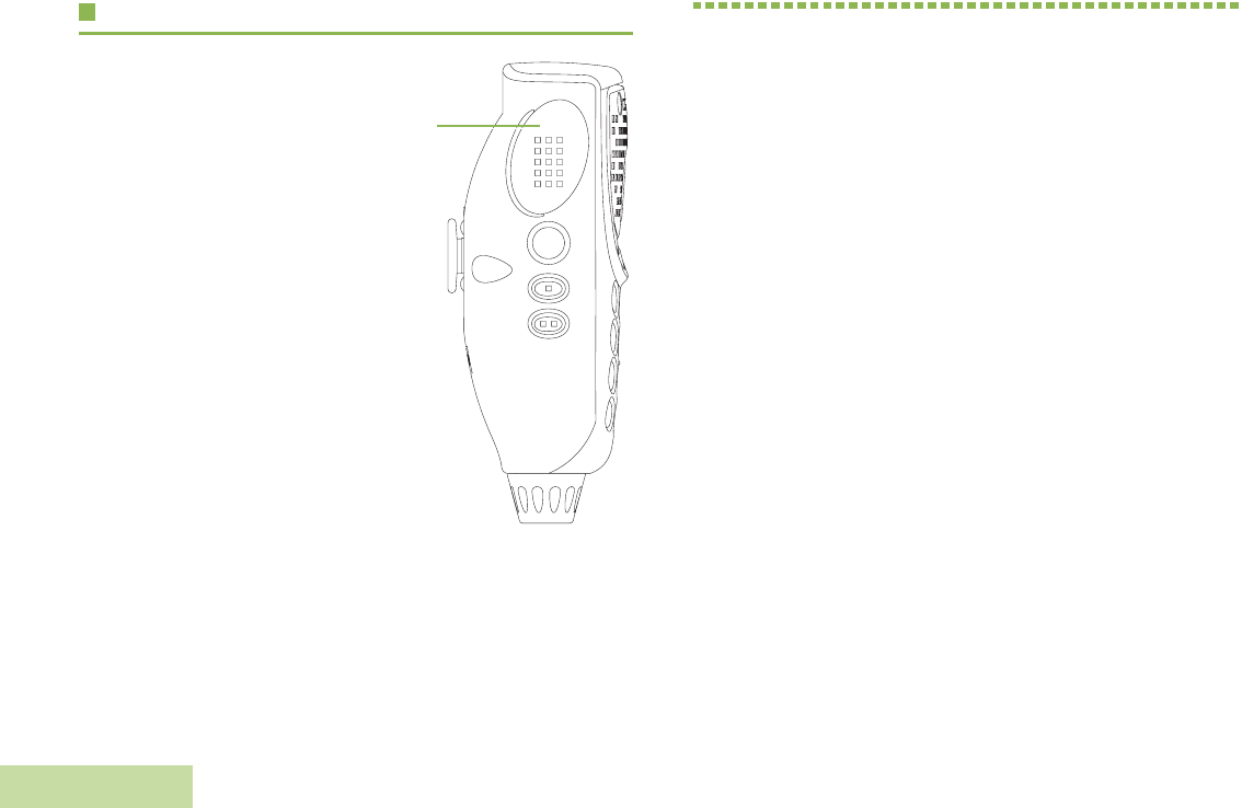
Push-To-Talk (PTT) Button
The PTT button on the side
of the microphone serves
two basic purposes:
•While a call is in progress,
the PTT button allows the
radio to transmit to other
radios in the call.
Press and hold down PTT
button to talk. Release the
PTT button to listen.
The microphone is
activated when the PTT
button is pressed.
•While a call is not in
progress, the PTT button
is used to make a new
call. See Making a Radio
Call on page 33 for more
information.
Identifying Status Indicators
Your radio indicates its operational status through the following:
Status Icons . . . . . . . . . . . . . . . . . . . . . . . . . . . . . . . . . page 17
Text Messaging Service (TMS) Icons . . . . . . . . . . . . . page 19
Status Icons . . . . . . . . . . . . . . . . . . . . . . . . . . . . . . . page 19
TMS Menu Options . . . . . . . . . . . . . . . . . . . . . . . . . page 20
Call Type Icons . . . . . . . . . . . . . . . . . . . . . . . . . . . . . . page 21
LED Indicator . . . . . . . . . . . . . . . . . . . . . . . . . . . . . . . . page 22
Intelligent Lighting Indicators . . . . . . . . . . . . . . . . . . . . page 23
Alert Tones. . . . . . . . . . . . . . . . . . . . . . . . . . . . . . . . . . page 24
Phone Call Display and Alert Prompts. . . . . . . . . . . . . page 27
PTT
Button

Identifying Status Indicators
English
17
Status Icons
The 480 x 272 pixel front liquid crystal display (LCD) of your
radio shows radio status, text entries, and menu entries. The
top two display rows contain color icons that indicate radio
operating conditions.
Selected icons are also shown on the first row of the 112 x 32
pixel top monochrome display screen of your radio.
The following icons are for the front display screen unless
indicated otherwise.
Receiving
Radio is receiving a call or data.
Transmitting
Radio is transmitting a call or data.
Call Received
Radio has received an Individual Call.
Received Signal Strength Indicator (RSSI)
The number of bars displayed represents the
received signal strength for the current site, for
trunking only. The more stripes in the icon, the
stronger the signal.
F
Direct
•On = Radio is currently configured for direct
radio-to-radio communication (during
conventional operation only).
•Off = Radio is connected with other radios
through a repeater.
Monitor (Carrier Squelch)
Selected channel is being monitored (during
conventional operation only).
In-Call User Alert
•On = The feature is enabled. Voice muting of
the affiliated trunking talkgroup or
selected conventional channel is
activated.
•Off = The feature is disabled. Voice muting of
the affiliated trunking talkgroup or
selected conventional channel is
deactivated.
Power Level
•L = Radio is set at Low power.
•H = Radio is set at High power.
Scan
Radio is scanning a scan list.
O
M
K
H or .
i

Identifying Status Indicators
English
18
Priority Channel Scan
•Blinking dot = Radio detects activity on
channel designated as
Priority-One.
•Steady dot = Radio detects activity on channel
designated as Priority-Two.
View/Program Mode
Radio is in the view or program mode.
•On steady = View mode
•Blinking = Program mode
Vote Scan Enabled
The vote scan feature is enabled.
Secure Operation
•On = Secure operation.
•Off = Clear operation.
•Blinking = Receiving an encrypted voice call.
AES Secure Operation
•On = AES Secure operation.
•Off = Clear operation.
•Blinking = Receiving an encrypted voice call.
k
m
l
Location Signal
•On = Location feature is enabled, and location
signal is available.
•Off = Location feature is disabled.
•Blinking = Location feature is enabled, but no
location signal is available.
User Login Indicator (IP Packet Data)
•On = User is currently associated with the
radio.
•Off = User is currently not associated with the
radio.
•Blinking = Device registration or user
registration with the server failed
due to an invalid username or pin.
Data Activity
Data activity is present.
Hexadecimal
Indicates that the text entry is currently in
hexadecimal mode.
Lightbar
Alternates between red and blue when the
lightbar is on.
G
n
o
Identifying Status Indicators
English
19
Text Messaging Service (TMS) Icons
This feature allows you to send and receive text messages. See
Text Messaging Service (TMS) on page 64 for more
information.
Status Icons
The following icons appear on the radio’s display when you
send and receive text messages.
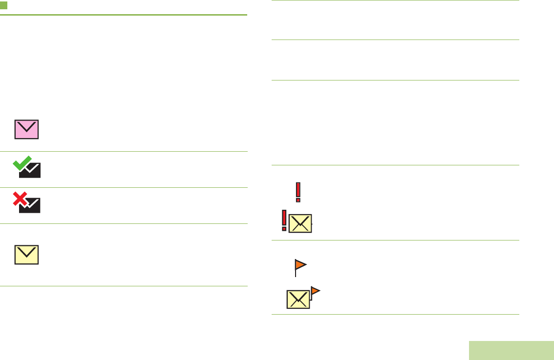
Inbox Full
The Inbox is full.
Message Sent
The text message is sent successfully.
Message Unsent
The text message cannot be sent.
Unread Message
•User receives a new message.
•The selected text message in the Inbox has not
been read.
Read Message
The selected text message in the Inbox has been
read.
Normal Message
User is composing a message with normal priority
and without a request for a reply.
3/6 Message Index
Indicates the index of the current message the
user is viewing.
Example: If the user is looking at the third
message out of a total of 6 messages in the Inbox
folder, the icon is displayed as the icon on the left
column.
Priority Status
•The “Priority” feature is toggled on before the
message is sent.
•Messages in the Inbox folder are flagged with
“Priority”.
Request Reply
•The “Request Reply” feature is toggled on
before the message is sent.
•Messages in the Inbox folder are flagged with
“Request Reply”.
Y
r
Identifying Status Indicators
English
20
TMS Menu Options
Priority Status and Request Reply
•User is composing a message with a priority
status and a request for a reply.
•Messages in the Inbox folder are flagged with
“Priority” and “Request Reply”.
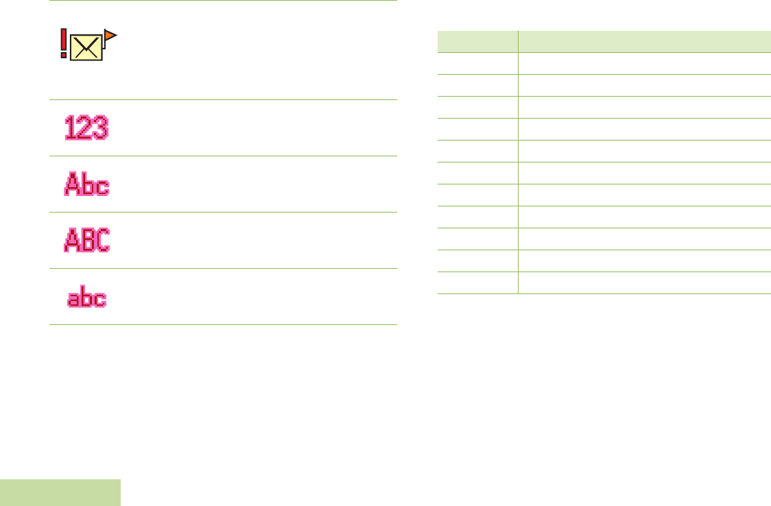
Numeric
Indicates that the text entry is currently in numeric
mode.
Mixed Case
Indicates that the text entry is currently in normal
text mode.
Uppercase
Indicates that the text entry is currently in
uppercase mode.
Lowercase
Indicates that the text entry is currently in
lowercase mode.
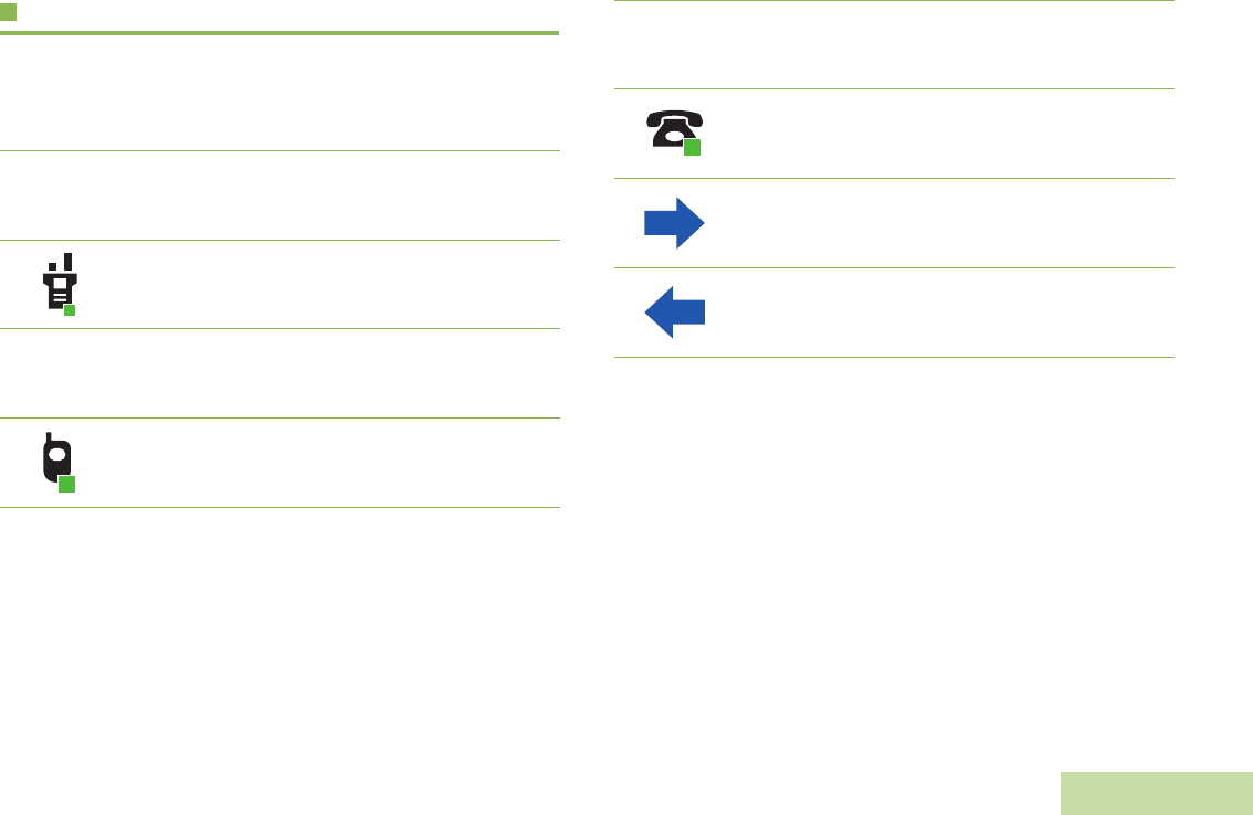
Menu Option Description/Function
Back Brings you back to the previous screen.
Clr Deletes all messages.
Del Deletes a message or text.
Edit Brings you to the edit screen.
Exit Exits to the Home screen.
No Returns to the previous screen.
Optn Brings you to the Options main screen.
Rply Replies to a message.
Sel Selects the highlighted command.
Send Sends the message.
Yes Updates or saves a command.
Identifying Status Indicators
English
21
Call Type Icons
The following icons appear on the radio’s main display, when
you make or receive a call, or view selected call lists, to indicate
the different call types associated with an alias or ID.
Radio number.
Radio number added to a Call List.
Mobile number.
Mobile number added to a Call List.
U
?
Landline phone number.
Landline phone number added to a Call List.
Incoming call or data.
Outgoing call or data.
%
Identifying Status Indicators
English
22
LED Indicator
The LED indicator shows the operational status of your radio.
Solid red – Radio is transmitting.
Rapidly blinking red – Radio has failed the self test upon
powering up or encountered a fatal error.
Solid yellow – Channel is busy.
Blinking yellow – Radio is receiving a secured transmission.
Solid green – Radio is powering up, or is on a non-priority
channel while in the Scan List Programming mode.
Blinking green – Radio is receiving an individual or telephone
call, or is on a Priority-Two channel while in the Scan List
Programming mode.
Rapidly blinking green – Radio is on a Priority-One channel
while in the Scan List Programming mode.
Red LED
Yellow LED
Green LED

Identifying Status Indicators
English
23
Intelligent Lighting Indicators
This feature temporary changes the backlight of the display screen and the keypad, and adds a color bar to the main display screen to
help signal that a radio event has occurred.
Note: This feature must be preprogrammed by a qualified radio technician.
Backlight and Bar Color Notification When
Orange Emergency Alerts The radio initiates an emergency alarm or call.
The radio receives an emergency alarm or call.
Red Critical Alerts
The radio is out of range.
The radio enters failsoft mode.
The radio is unable to establish a full connection with the system.
Green Call Alerts
The radio receives a private call.
The radio receives a phone call.
The radio receives a call alert.
The radio receives a selective call.

Identifying Status Indicators
English
24
Alert Tones
An alert tone is a sound or group of sounds. Your radio uses alert tones to inform you of your radio’s conditions. The following table
lists these tones and when they occur.
You Hear Tone Name Heard
Short,
Low-Pitched
Tone
Radio Self Test Fail When radio fails its power-up self test.
Reject When unauthorized request is made.
Time-Out Timer Warning Four seconds before time out.
No ACK Received When radio fails to receive an acknowledgment.
Individual Call
Warning Tone When radio is in an individual call for greater than 6 seconds without any activity.
Long,
Low-Pitched
Tone
Time-Out Timer
Timed Out After time out.
Talk Prohibit/PTT Inhibit (When PTT button is pressed) transmissions are not allowed.
Out of Range (When PTT button is pressed) the radio is out of range of the system.
Invalid Mode When radio is on an unpreprogrammed channel.
A Group of
Low-Pitched
Tones
Busy When system is busy.

Identifying Status Indicators
English
25
Short,
Medium-Pitched
Tone
Valid Key-Press When correct key is pressed.
Radio Self Test Pass When radio passes its power-up self test.
Clear Voice At beginning of a non-coded communication.
Priority Channel
Received When activity on a priority channel is received.
Emergency Alarm Entry When entering the emergency state.
Central Echo When central controller has received a request from a radio.
Long,
Medium-Pitched
Tone
Volume Set When volume is changed on a quiet channel.
Emergency Exit When exiting the emergency state.
A Group of
Medium-Pitched
Tones
Failsoft When the trunking system fails.
Automatic Call Back When voice channel is available from previous request.
Talk Permit (When PTT button is pressed) verifying system accepting transmissions.
Keyfail When encryption key has been lost.
Console Acknowledge When status, emergency alarm, or reprogram request ACK is received.
Received Individual Call When Call Alert or Private Call is received.
Call Alert Sent When Call Alert is received by the target radio.
Site Trunking When a SmartZone trunking system fails.
You Hear Tone Name Heard

Identifying Status Indicators
English
26
Ringing
Fast Ringing When system is searching for target of Private Call.
Enhanced Call Sent When waiting for target of Private Call to answer the call.
Phone Call Received When a land-to-mobile phone call is received.
Gurgle Dynamic Regrouping (When the PTT button is pressed) a dynamic ID has been received.
Unique,
Low-Pitched
Chirp
New Message When a new message is received.
Unique,
High-Pitched
Chirp
Priority Status When a priority message is received.
You Hear Tone Name Heard

Identifying Status Indicators
English
27
Phone Call Display and Alert Prompts
The following appears on the radio’s display when you make and receive Phone calls. The radio also uses alert tones to indicate the
current status.
You Hear You See When Notes
A Long
Tone
No phone You press the PTT button and the
phone system is not available. Press H to hang up. The radio returns to the Home screen.
Phone busy The phone system is busy. Press H to exit the phone mode and try your call later.
A Busy
Tone Phone busy When a channel is not available. The radio automatically connects when a channel opens.
–No
acknowledge The call is not acknowledged. Press H to hang up. The radio returns to the Home screen.
A High-
Pitched
Tone –When you release the PTT button. The radio indicates to the landline party that he or she may begin
talking.
Note: You have the option of sending additional digits (overdial), such as an extension number, or credit card or PIN numbers, to the
phone system. If the radio is preprogrammed for live overdial, every digit entered after the call is connected is sent to the
phone system.
If the radio is preprogrammed for buffered overdial, the digits pressed are entered into memory and then sent when the PTT
button is pressed. Press the PTT button to send either digits or voice, but not both at the same time.

General Radio Operation
English
28
General Radio Operation
Once you understand how your APX 7500 Mobile is configured,
you are ready to use your radio.
Use this navigation guide to familiarize yourself with the basic
Call features:
Selecting a Zone . . . . . . . . . . . . . . . . . . . . . . . . . . . . . page 28
Selecting a Radio Channel . . . . . . . . . . . . . . . . . . . . . page 29
Receiving and Responding to a Radio Call. . . . . . . . . page 30
Making a Radio Call . . . . . . . . . . . . . . . . . . . . . . . . . . page 33
Repeater or Direct Operation . . . . . . . . . . . . . . . . . . . page 36
Monitoring Features . . . . . . . . . . . . . . . . . . . . . . . . . . page 36
Selecting a Zone
A zone is a group of channels.
Use the following procedure to select a zone.
Note: Your radio must be preprogrammed to allow you to use
this feature.
Procedure:
Rotate the Mode knob until the display shows the desired zone.
OR
1< or > to Zone.
2Press the Menu Select button directly below Zone.
3U or D to the required zone.
OR
Use the keypad to enter the zone number.
4If the zone number entered is unprogrammed, the display
shows Invalid entry. Repeat Step 3.
OR
Press the Menu Select button directly below Select to
confirm the displayed zone.
Press the PTT button to transmit on the displayed zone
channel.

General Radio Operation
English
29
Selecting a Radio Channel
A channel is a group of radio characteristics, such as transmit/
receive frequency pairs.
Use the following procedure to select a channel.
Note: Your radio must be preprogrammed to allow you to use
this feature. If you select a channel that is not within the
preprogrammed band, the radio indicates that it is on
an unsupported frequency with both audio and visual
warnings.
Procedure:
Rotate the Mode knob until the display shows the desired
channel.
OR
1< or > to Channel.
2Press the Menu Select button directly below Channel.
3U or D to the required channel.
OR
Use the keypad to enter the channel number.
4If the channel number entered is unprogrammed, the display
shows Invalid entry. Repeat Step 3.
OR
Press the Menu Select button directly below Select to
confirm the selected channel.
Press the PTT button to transmit on the displayed zone
channel.
General Radio Operation
English
30
Receiving and Responding to a Radio Call
Once you have selected the required channel and/or zone, you
can proceed to receive and respond to calls.
The LED lights up solid red while the radio is transmitting, and
solid yellow when the radio is receiving a transmission
(conventional mode only). There is no LED indication when the
radio receives a transmission in trunking mode.
If the radio is receiving a secure transmission, the LED blinks
yellow.
Receiving and Responding to a Talkgroup Call
To receive a call from a group of users, your radio must be
configured as part of that talkgroup.
Procedure:
When you receive a talkgroup call (while on the Home screen),
depending on how your radio is preprogrammed:
1ASTRO Conventional Only:
The LED lights up solid yellow. The display shows the
talkgroup alias or ID, and the caller alias or ID.
OR
Trunking Only:
The display shows the caller alias or ID.
2Hold the microphone vertically 1 to 2 inches (2.5 to 5.0 cm)
from your mouth.
3Press the PTT button to respond to the call. The LED lights
up solid red.
4Release the PTT button to listen.
See Making a Talkgroup Call on page 33 for details on making
a Talkgroup Call.
Red LED
Yellow LED
Green LED

General Radio Operation
English
31
Receiving and Responding to a Private Call
(Trunking Only)
A Private Call is a call from an individual radio to another
individual radio.
These one-to-one calls between two radios are not heard by
others in the current talkgroup. The calling radio automatically
verifies that the receiving radio is active on the system and can
display the caller ID.
Note: The radio automatically exits the feature, if the feature
inactivity timer is enabled, when the radio is left idle
and the timer expires. You will hear the Menu Inactive
Exit Tone upon feature exit.
Procedure:
When you receive a Private Call:
1You hear two alert tones and the LED blinks green. The
display shows Call received and the call received icon
blinks.
2Press the Menu Select button directly below Resp.
OR
Press the Call Response button within 20 seconds after the
call indicators begin.
3During the call, the display shows the caller alias (name), if it
is in the call list.
OR
During the call, the display shows the caller ID (number), if
the caller’s name is not in the call list.
4Press and hold the PTT button to talk. Release the PTT
button to listen.
5Press H or the Call Response button to hang up and
return to the Home screen.
Note: If you press PTT button before pressing the Menu
Select button directly below Resp, your conversation
will be heard by all members of the talk group.
If 20 seconds pass before you press the Menu Select
button directly below the Resp, you will not respond
privately to the call just received. Instead, you initiate a
Private Call.
See Making a Private Call (Trunking Only) on page 33 for
details on making a Private Call.

General Radio Operation
English
32
Receiving and Responding to a Telephone Call
(Trunking Only)
This feature allows you to receive calls similar to standard
phone calls from a landline phone.
Note: The radio automatically exits the feature, if the feature
inactivity timer is enabled, when the radio is left idle
and the timer expires. You will hear the Menu Inactive
Exit Tone upon feature exit.
Procedure:
Use the preprogrammed Call Response button to answer a
Telephone Call:
1You hear a telephone-type ringing and the LED blinks green.
The backlight of the screen and the bar turns green. The
display shows Phone Call and the call received icon blinks.
2Press the Call Response button within 20 seconds after the
call indicators begin.
3Press and hold the PTT button to talk. Release the PTT
button to listen.
4Press H or the Call Response button to hang up and
return to the Home screen.
OR
Use the Menu Select button to answer a Telephone Call:
1You hear a telephone-type ringing and the LED blinks green.
The backlight of the screen turns green. The display shows
Phone call and the call received icon blinks.
2Press the Menu Select button directly below Resp.
3Press and hold the PTT button to talk. Release the PTT
button to listen.
4Press H or the Menu Select button directly below EXIT to
hang up and return to the Home screen.
See Making a Telephone Call (Trunking Only) on page 35 for
details on making a Telephone Call.

General Radio Operation
English
33
Making a Radio Call
You can select a zone, channel, subscriber ID, or talkgroup by
using:
•The preprogrammed Zone switch
•The Mode Knob
•A preprogrammed One Touch Call button
•The Contacts list (see Viewing Details of a Contact on
page 49)
Note: The radio automatically exits the feature, if the feature
inactivity timer is enabled, when the radio is left idle
and the timer expires. You will hear the Menu Inactive
Exit Tone upon feature exit.
Making a Talkgroup Call
To make a call to a group of users, your radio must be
configured as part of that talkgroup.
Procedure:
1> or < to TalkGrp and press the Menu Select button directly
below TalkGrp.
The display shows the last-selected talkgroup.
Press the Menu Select button directly below Select.
OR
Turn the Mode Knob to select the channel with the desired
talkgroup.
2Hold the microphone vertically 1 to 2 inches (2.5 to 5.0 cm)
from your mouth.
3Press the PTT button to make the call.
4ASTRO Conventional Only:
The LED lights up solid red. The display shows the
talkgroup alias or ID.
OR
Trunking Only:
The LED lights up solid red.
5Speak clearly into the microphone.
6Release the PTT button to listen.
Making a Private Call (Trunking Only)
Procedure:
Press the preprogrammed Quick Access (One-Touch) Private
Call button to dial the preprogrammed ID (number) and proceed
to Step 5.
OR
Follow the procedure below.
1< or > to Call.

General Radio Operation
English
34
2Press the Menu Select button directly below Call. The
display shows the last transmitted ID, received ID and your
radio ID.
3U or D to the required ID.
OR
Press the Menu Select button directly below Cntacts to
scroll through and select the required ID.
OR
Use the keypad to enter the required ID.
4Press the PTT button to start the Private Call.
5The display shows Calling... <Number> or Calling...
<Alias>.
6Hold the microphone vertically 1 to 2 inches (2.5 to 5.0 cm)
from your mouth.
7When you are connected, the display shows the ID of the
target radio. Press and hold the PTT button to talk. Release
the PTT button to listen.
OR
If no acknowledgment is received, the display shows No
acknowledge.
8Press H to return to the Home screen.
Making an Enhanced Private Call (Trunking Only)
This feature allows you to send an individual Call Alert page if
there is no answer from the target radio. See Sending a Call
Alert Page on page 56 for more information.
Note: Your radio must be preprogrammed to allow you to use
this feature.
Procedure:
Press the preprogrammed Quick Access (One-Touch)
Enhanced Private Call button to dial the preprogrammed ID
and proceed to Step 5.
OR
Follow the procedure below.
1< or > to Call.
2Press the Menu Select button directly below Call. The
display shows the last transmitted ID, received ID and your
radio ID.
3U or D to the required ID.
OR
Press the Menu Select button directly below Cntacts to
scroll through and select the required ID.
OR
Use the keypad to enter the required ID.
4Press the PTT button to start the Private Call.

General Radio Operation
English
35
5The display shows Calling... <Number> or Calling...
<Alias>.
6Hold the radio vertically 1 to 2 inches (2.5 to 5.0 cm) from
your mouth.
7When you are connected, the display shows the ID of the
target radio. Press and hold the PTT button to talk. Release
the PTT button to listen.
OR
If no acknowledgment is received, the display shows No
acknowledge.
OR
If the target radio does not respond before the time out, the
display shows No answer.
8Press H to return to the Home screen.
Making a Telephone Call (Trunking Only)
This feature allows you to make calls similar to standard phone
calls to a mobile or landline phone.
Procedure:
Press the preprogrammed Quick Access (One-Touch) Phone
Call button to dial the preprogrammed phone number and
proceed to Step 5.
OR
Follow the procedure below.
1< or > to Phone.
2Press the Menu Select button directly below Phone. The
display shows the last transmitted and received phone
number.
3U or D to the required phone number.
OR
Press the Menu Select button directly below Cntacts to
scroll through and select the required ID.
OR
Use the keypad to enter the required phone number.
4Press and release the PTT button to dial the phone number.
5Hold the microphone vertically 1 to 2 inches (2.5 to 5.0 cm)
from your mouth.
6When your call is answered, press the PTT button to talk.
Release the PTT button to listen.
7Press H to return to the Home screen.
See Phone Call Display and Alert Prompts on page 27 for
more information if your call is NOT answered.

General Radio Operation
English
36
Repeater or Direct Operation
The REPEATER operation increases the radio’s range by
connecting with other radios through a repeater. The transmit
and receive frequencies are different.
The DIRECT or “talkaround operation” allows you to bypass the
repeater and connect directly to another radio. The transmit and
receive frequencies are the same.
Procedure:
Press the preprogrammed Repeater/Direct switch to toggle
between talkaround and repeater modes.
OR
Follow the procedure below.
1< or > to Direct.
2Press the Menu Select button directly below Direct.
3The display shows Repeater mode if the radio is currently
in Repeater mode.
OR
The display shows Direct mode and the Talkaround icon if
the radio is currently in Direct mode (during conventional
operation only).
Monitoring Features
Radio users who switch from analog to digital radios often
assume that the lack of static on a digital channel is an
indication that the radio is not working properly. This is not the
case.
Digital technology quiets the transmission by removing the
“noise” from the signal and allowing only the clear voice or data
information to be heard.
Use the Monitor feature to make sure a channel is clear before
transmitting.
Monitoring a Channel
Procedure:
Lift the microphone off hook.
Conventional Modes Only:
1Listen for activity on that channel.
2Adjust the Volume knob if necessary.
3If you hear no activity, press and hold the PTT button to start
OR
Trunked Modes Only:
1Press the PTT button.

General Radio Operation
English
37
2If you hear two, short, high-pitched tones, or if you hear no
tone and the t indicator lights steadily, then proceed with
your message.
3Release the PTT button to receive (listen).
If you are not in the range of the system, you may hear a
continuous low-pitched tone and the display shows
Out of
range
.
Conventional Mode Operation
This feature allows you to monitor channel traffic on
conventional channels by defeating the coded squelch. Thus,
you can to listen to another user active on the channel. This
way, you may be prevented from talking over someone else’s
conversation.
Note: This feature must first be enabled by a qualified radio
technician or system administrator.
Procedure:
Take the control head off hook. (This is the same as monitor on.
You hear all channel traffic.)
OR
1At Home mode where the default zone and channel are
being displayed, > or < button to Monitor.
2Press the Menu Select button directly below Monitor
momentarily to activate monitoring. The display shows
Monitor on.
3Press the Menu Select button to deactivate the monitoring.
The display shows Monitor off.
Monitor on
shown on the display indicates that the radio is
monitoring. Pressing the Menu Select button again turns
monitor off and you don’t hear all channel traffic.
If you try to transmit on a receive-only channel, you hear an
invalid tone until you release the PTT button.

Advanced Features
English
38
Advanced Features
Use this navigation guide to learn more about advanced
features available with your radio:
Advanced Call Features . . . . . . . . . . . . . . . . . . . . . . . page 38
Contacts . . . . . . . . . . . . . . . . . . . . . . . . . . . . . . . . . . . page 43
Scan Lists . . . . . . . . . . . . . . . . . . . . . . . . . . . . . . . . . . page 50
Scan . . . . . . . . . . . . . . . . . . . . . . . . . . . . . . . . . . . . . . page 52
Call Alert Paging . . . . . . . . . . . . . . . . . . . . . . . . . . . . . page 55
Emergency Operation . . . . . . . . . . . . . . . . . . . . . . . . . page 58
Automatic Registration Service (ARS) . . . . . . . . . . . . page 62
Text Messaging Service (TMS) . . . . . . . . . . . . . . . . . . page 64
Secure Operations . . . . . . . . . . . . . . . . . . . . . . . . . . . page 76
Security . . . . . . . . . . . . . . . . . . . . . . . . . . . . . . . . . . . . page 80
The Global Positioning System (GPS) . . . . . . . . . . . . page 82
Trunking System Controls. . . . . . . . . . . . . . . . . . . . . . page 90
Utilities. . . . . . . . . . . . . . . . . . . . . . . . . . . . . . . . . . . . . page 94
Advanced Call Features
Calling a Phone Not in the List
1> or < to Phone.
2Press the Menu Select button directly below Phone.
3Enter the desired phone number on the keypad. The display
updates as the numbers are entered.
4Press 3 button on the keypad microphone to make the call.
5Press and hold the PTT button to talk. Release the PTT
button to listen.
6Press H or Menu Select button directly below Phone to
exit.

Advanced Features
English
39
Receiving and Making a Selective Call (ASTRO
Conventional Only)
This feature allows you to receive a call from or to call a specific
individual. It is intended to provide privacy and to eliminate the
annoyance of having to listen to conversations that are of no
interest to you.
Receiving a Selective Call
Procedure:
1When you receive a Selective Call, you hear two alert tones
and the LED lights up solid yellow. The call received icons
blinks and the display shows Call received.
2The speaker unmutes.
3Hold the microphone vertically 1 to 2 inches (2.5 to 5.0 cm)
from your mouth.
4Press and hold the PTT button to talk. Release the PTT
button to listen.
5Press H to return to the Home screen.
Note: If you press PTT button before pressing the Menu
Select button directly below Call, your conversation
will be heard by all members of the talk group.
If 20 seconds pass before you press the Menu Select button
directly below the
Call
, you will not respond privately to the call
just received. Instead, you initiate a Selective Call. See Making
a Selective Call on page 39.
Making a Selective Call
Procedure:
Press the preprogrammed Quick Access (One-Touch)
Selective Call button to dial the preprogrammed ID and
proceed to Step 4.
OR
Follow the procedure below.
1< or > to Call.
2Press the Menu Select button directly below Call. The
display shows the last transmitted or received ID.
3U or D to the required ID.
OR
Press the Menu Select button directly below Cntacts to
scroll through and select the required ID.
OR
Use the keypad to enter the required ID.
4Hold the radio vertically 1 to 2 inches (2.5 to 5.0 cm) from
your mouth.
5Press and hold the PTT button to start the Selective Call.
The display shows the ID of the target radio.

Advanced Features
English
40
6Release the PTT button to listen.
7Press H to return to the Home screen.
Using the Talkgroup Call Feature (Conventional
Operation Only)
This feature allows you to define a group of conventional
system users so that they can share the use of a conventional
channel.
Note: Encryption keys are associated to talkgroups. When
talkgroups are associated, encryption keys are
changed by changing the active talkgroup. See Secure
Operations on page 76 for more information.
Selecting a Talkgroup
Procedure:
1< or > to TalkGrp.
2Press the Menu Select button directly below TalkGrp. The
display shows the last talkgroup that was selected and
stored, Select and Exit.
3U or D to Preset for the preset preprogrammed talkgroup.
OR
U or D to the required talkgroup.
OR
Use the keypad to enter the number of the corresponding
talkgroup in the list.
4Press the Menu Select button directly below Select to save
the currently selected talkgroup and return to the Home
screen.
5If the encryption key associated to the new talkgroup is
erased, a momentary key fail tone sounds and the display
shows Key fail.
OR
If the encryption key that is associated to the new talkgroup
is not allowed, a momentary key fail tone sounds and the
display shows Illegal key.
6Press H or the PTT button to exit.

Advanced Features
English
41
Sending a Status Call
This feature allows you to send data calls to the dispatcher
about a predefined status.
Each status can have up to a 14-character name. A maximum
of eight status conditions is possible.
Note: The radio automatically exits the feature, if the feature
inactivity timer is enabled, when the radio is left idle
and the timer expires. You will hear the Menu Inactive
Exit Tone upon feature exit.
Procedure:
Press the preprogrammed Status button and proceed to
Step 3.
OR
Follow the procedure below.
1< or > to Status.
2Press the Menu Select button directly below Status.
3The display shows the last acknowledged status call, or the
first status in the list.
4U or D to the required status.
OR
Use the keypad to enter a number corresponding to the
location in the status list.
5Press the PTT button to send the status.
6When the dispatcher acknowledges, four tones sound and
the display shows Ack received. The radio returns to
normal dispatch operation.
OR
If no acknowledgment is received, a low-pitched tone
sounds and the display shows No acknowledge.
7Press H to return to the Home screen.
No traffic is heard on trunked channels while Status Calls is
selected. If the radio detects no Status Call activity for six
seconds, an alert tone sounds until you press H or the PTT
button.
Using the Dynamic Regrouping Feature (Trunking
Only)
This feature allows the dispatcher to temporarily reassign
selected radios to a single special channel so they can
communicate with each other. This feature is typically used
during special operations and is enabled by a qualified radio
technician.
You will not notice whether your radio has this feature enabled
until a dynamic regrouping command is sent by the dispatcher.
Note: If you try to access a zone or channel that has been
reserved by the dispatcher as a dynamically regrouped
mode for other users, an invalid tone sounds.

Advanced Features
English
42
Procedure:
1When your radio is dynamically regrouped, it automatically
switches to the dynamically regrouped channel. A “gurgle”
tone sounds and the display shows the dynamically
regrouped channel’s name.
2Press the PTT button to talk. Release PTT button to listen.
When the dispatcher cancels dynamic regrouping, the radio
automatically returns to the zone and channel that you were
using before the radio was dynamically regrouped.
Requesting a Reprogram (Trunking Only)
This feature lets you notify the dispatcher that you want a new
dynamic regrouping assignment.
Procedure:
Press the preprogrammed Reprogram Request button to send
reprogram request to the dispatcher and proceed to Step 3.
OR
Follow the procedure below.
1< or > to Rpgm.
2Press the Menu Select button directly below Rpgm to send
reprogram request to the dispatcher.
3The display shows Reprgrm rqst and Please wait.
4If you hear five beeps, the dispatcher has acknowledged the
reprogram request. The display shows Ack received and
the radio returns to the Home screen.
OR
If the dispatcher does not acknowledge the reprogram
request within six seconds, a low-pitched alert tone sounds
and the display shows No acknowledge.
Try again or press H to cancel and return to the Home
screen.
Classifying Regrouped Radios
The dispatcher can classify regrouped radios into either of two
categories: Select Enabled or Select Disabled.
•Select-enabled radios are free to change to any available
channel, including the dynamic-regrouping channel, once the
user has selected the dynamic-regrouping position.
•Select-disabled radios cannot change channels while
dynamically regrouped. The dispatcher has forced the radio
to remain on the dynamic-regrouping channel.
The Scan or Private Call feature cannot be selected while your
radio is Select Disabled.

Advanced Features
English
43
Contacts
This feature provides “address-book” capabilities on your radio.
Each entry corresponds to an alias (name) or ID (number) that
you use to initiate a call.
Contacts manages up to 2,500 contact entries, alphabetically
sorted according to entry alias. Each alias can have up to 5 IDs
of different call types associated with it.
Additionally, each entry, depending on context (conventional,
trunking, or phone), associates with one or more of the four
types of calls: Phone Call, Selective Call, Private Call, or Call
Alert.
Each entry within Contacts displays the following information:
•Call Alias (Name)
•Call ID (Number)
•Call Type (Icon)
•WACN ID (Astro 25 Trunking IDs only)
•System ID
Note: Your radio must be preprogrammed to allow you to
add, edit, or delete the contact entries.
Your radio also supports a maximum of 50 call lists. Each list
can store up to 100 IDs (numbers).
Note: Your radio is preprogrammed with a number of
contacts per Call Lists. Check with your dealer or
system administrator for more information.
The radio automatically exits the feature, if the feature
inactivity timer is enabled, when the radio is left idle
and the timer expires. You will hear the Menu Inactive
Exit Tone upon feature exit.
Making a Private Call from Contacts
Note: Your radio must be preprogrammed to allow you to
use this feature.
Procedure:
Use the Options Menu.
1< or > to Cntacts.
2Press the Menu Select button directly below Cntacts. The
entries are alphabetically sorted.
3U or D to the required subscriber alias.
4Press the Menu Select button directly below Options.
5U or D to Call and press the Menu Select button directly
below Select.
6U or D to select the call type.

Advanced Features
English
44
7Hold the microphone vertically 1 to 2 inches (2.5 to 5.0 cm)
from your mouth.
8Press the PTT button to initiate the call. During the call, the
display shows the subscriber alias.
9Press and hold the PTT button to talk. The LED lights up
solid red.
OR
Release the PTT button to listen.
10 If there is no voice activity for a preprogrammed period of
time, the call ends.
OR
The call ends when it reaches the maximum ring time.
OR
Use the PTT button.
1< or > to Cntacts.
2Press the Menu Select button directly below Cntacts. The
entries are alphabetically sorted.
3U or D to the required subscriber alias.
4< or > to scroll through the available IDs for the selected
subscriber alias.
5Hold the microphone vertically 1 to 2 inches (2.5 to 5.0 cm)
from your mouth.
6Press the PTT button to initiate the call. During the call, the
display shows the subscriber alias.
7Press and hold the PTT button to talk. The LED lights up
solid red.
OR
Release the PTT button to listen. The LED lights up solid
yellow.
8If there is no voice activity for a preprogrammed period of
time, the call ends.
OR
The call ends when it reaches the maximum ring time.
Adding a New Contact Entry
Procedure:
1< or > to Cntacts.
2Press the Menu Select button directly below Cntacts. The
entries are alphabetically sorted.
3U or D to {New Contact} and press the Menu Select
button directly below Select.
4U or D to Name and press the Menu Select button directly
below Edit.
5The display shows Edit Name and a blinking cursor
appears.
Use the keypad to enter the name.

Advanced Features
English
45
Press < to move one space to the left.
Press > to move one space to the right.
Press the Menu Select button directly below Delete to
delete any unwanted characters.
Press J to add a space.
Press K to toggle between mixed case mode, uppercase
mode, and lowercase mode.
Press L to toggle between numeric and letter mode.
6Press the Menu Select button directly below OK once you
have entered the name.
OR
Press the Menu Select button directly below Cancel to
return to the previous screen.
7U or D to {Add Number} and press the Menu Select button
directly below Select.
8U or D to Number 1 and press the Menu Select button
directly below Edit.
9The display shows Edit Number 1 and a blinking cursor
appears.
Use the keypad to enter the number.
Press < to move one space to the left.
Press > to move one space to the right.
Press the Menu Select button directly below Delete to
delete any unwanted characters.
10 Press the Menu Select button directly below OK once you
have entered the number.
OR
Press the Menu Select button directly below Cancel to
return to the previous screen.
11 U or D to Type 1 and press the Menu Select button directly
below Edit.
U or D to the required mode and press the Menu Select
button directly below OK.
OR
Repeat Steps 8 through 10 to enter or edit the existing
system IDs.
OR
U or D to {Add Number} and press the Menu Select button
directly below Select to add a new number. Repeat Steps 8
through 10.
12 Press the Menu Select button directly below Done once you
have finished.

Advanced Features
English
46
13 The display shows <Entry> Stored, confirming that the
contact entry has been added.
14 The radio returns to the main Contacts screen.
Deleting a Contact Entry
Procedure:
1< or > to Cntacts.
2Press the Menu Select button directly below Cntacts. The
entries are alphabetically sorted.
3U or D to the entry you want to delete and press the Menu
Select button directly below Options.
4U or D to Delete and press the Menu Select button directly
below Select.
5The display shows Delete <Entry> confirm?.
6Select Yes to delete the entry.
The display shows <Entry> deleted and the radio returns
to the main screen for Contacts.
OR
Select No to return to the main screen for Contacts.
Adding a Contact to a Call List
Procedure:
1< or > to Cntacts.
2Press the Menu Select button directly below Cntacts. The
entries are alphabetically sorted.
3U or D to the entry you want to add to a call list and press
the Menu Select button directly below Options.
4U or D to Add to CallLst and press the Menu Select button
directly below Select.
5U or D to the required Call List and press the Menu Select
button directly below Add.
OR
U or D to Cancel to return to the main display for Contacts.
6The display momentarily shows Please wait before
showing <Entry> added to Call List, confirming the
addition of the contact to the list.
7The radio returns to the main display for Contacts.

Advanced Features
English
47
Removing a Contact from a Call List
Procedure:
1< or > to Cntacts.
2Press the Menu Select button directly below Cntacts. The
entries are alphabetically sorted.
3U or D to the entry you want to remove from a call list and
press the Menu Select button directly below Options.
4U or D to Delete and press the Menu Select button directly
below Select.
5The display shows Delete <Entry> confirm?.
6Press the Menu Select button directly below Yes to remove
the entry from the Call List.
OR
Press the Menu Select button directly below No to return to
the main display for Contacts.
7The display momentarily shows <Entry> deleted,
confirming the removal of the contact from the list.
8The radio returns to the main display for Contacts.
Editing a Contact in a Call List
Editing an Entry Alias
Procedure:
1< or > to Cntacts.
2Press the Menu Select button directly below Cntacts. The
entries are alphabetically sorted.
3U or D to the entry you want to edit and press the Menu
Select button directly below Options.
4U or D to Edit and press the Menu Select button directly
below Select.
5U or D to the entry alias you wish to change and press the
Menu Select button directly below Edit.
6A blinking cursor appears.
Use the keypad to edit the name.
Press < to move one space to the left.
Press > to move one space to the right.
Press the Menu Select button directly below Delete to
delete any unwanted characters.
Press J to add a space.
Press K to toggle between mixed case mode, uppercase
mode, and lowercase mode.
Press L to toggle between numeric and letter mode.

Advanced Features
English
48
7Press the Menu Select button directly below OK once you
have finished. The display returns to the Edit Contact
screen.
8Press the Menu Select button directly below Done to save
your changes and return to the main screen for Contacts.
Editing as Entry ID
Procedure:
1< or > to Cntacts.
2Press the Menu Select button directly below Cntacts. The
entries are alphabetically sorted.
3U or D to the entry you want to edit and press the Menu
Select button directly below Options.
4U or D to Edit and press the Menu Select button directly
below Select.
5U or D to the entry ID you wish to change and press the
Menu Select button directly below Edit.
6A blinking cursor appears.
Use the keypad to edit the name.
Press < to move one space to the left.
Press > to move one space to the right.
Press the Menu Select button directly below Delete to
delete any unwanted characters.
Press J to add a space.
Press K to toggle between mixed case mode, uppercase
mode, and lowercase mode.
Press L to toggle between numeric and letter mode.
7Press the Menu Select button directly below OK once you
have finished. The display returns to the Edit Contact
screen.
8Press the Menu Select button directly below Done to save
your changes and return to the main screen for Contacts.

Advanced Features
English
49
Editing a Call Type
Procedure:
1< or > to Cntacts.
2Press the Menu Select button directly below Cntacts. The
entries are alphabetically sorted.
3U or D to the entry you want to edit and press the Menu
Select button directly below Options.
4U or D to Edit and press the Menu Select button directly
below Select.
5U or D to Type and press the Menu Select button directly
below Edit.
6U or D to choose from the list of call types given and press
the Menu Select button directly below OK to select.
7The display returns to the Edit Contact screen.
8Press the Menu Select button directly below Done to save
your changes and return to the main screen for Contacts.
Viewing Details of a Contact
Procedure:
1< or > to Cntacts.
2Press the Menu Select button directly below Cntacts. The
entries are alphabetically sorted.
3U or D to the entry you want to view and press the Menu
Select button directly below Options.
4U or D to View and press the Menu Select button directly
below Select.
5The display shows all the numbers associated with the
entry.

Advanced Features
English
50
Scan Lists
Scan lists are created and assigned to individual channels/
groups. Your radio scans for voice activity by cycling through
the channel/group sequence specified in the scan list for the
current channel/group.
Your radio can support up to 125 different scan lists. These lists
must be preprogrammed by a qualified radio technician.
Viewing a Scan List
Procedure:
1< or > to ScanList.
2Press the Menu Select button directly below ScanList.
3U or D to view the members on the list.
4Press H to exit the current display and return to the Home
screen.
Editing the Scan List
This feature lets you change scan list members and priorities.
Note: The maximum number of members for a trunking
priority monitor scan list is 50; for a conventional scan
list, 30; and for a talkgroup scan list, 250.
Procedure:
1Long press the preprogrammed side button and proceed to
Step 3.
OR
< or > to ScanList.
2Press the Menu Select button directly below ScanList. The
display shows the lists that can be changed.
3U or D to the entry you want to edit.
4Press the Menu Select button directly below Select to add
and/or change the priority of the currently displayed channel
in the scan list.
OR
Press the Menu Select button directly below Delete to
delete the currently displayed channel from the scan list.
OR
Press the Menu Select button directly below Recall to view
the next member of the scan list.

Advanced Features
English
51
5U or D to select more channels to be added or deleted.
OR
Use the keypad to go directly to additional channels to be
added or deleted.
OR
Use the Mode knob to select additional channels to be
added or deleted.
6Press H to exit scan list programming and return to the
Home screen.
See Viewing and Changing the Priority Status on page 52 for
more information on how to add and/or change the priority of
the currently displayed channel in the scan list.
Changing the Scan List Status
Procedure:
1Long press the preprogrammed side button and proceed to
Step 3.
OR
< or > to ScanList.
2Press the Menu Select button directly below ScanList. The
display shows the lists that can be changed.
3U or D to the number you want to edit.
4Press the Select button once to add the currently displayed
channel to the scan list.
OR
Press the Select button one or more times to change the
scan list status icon of the currently displayed channel.
5U or D to select more list members whose scan status you
want to change.
OR
Use the keypad to go directly to that scan list member.
OR
Use the Mode knob to select another scan list member.
6Press H to exit scan list programming and return to the
Home screen.

Advanced Features
English
52
Viewing and Changing the Priority Status
Procedure:
1Below the Select, Delete, and Recall screen, press the
Menu Select button directly below Select to view and/or
change the priority status of the currently displayed channel.
OR
Below the Select, Delete, and Recall screen, press the
Select button one or more times to view and/or change the
scan list status icon of the currently displayed channel.
2A Scan icon indicates that the current channel is in the scan
list as a non-priority channel. The LED lights up solid green.
OR
A Priority-Two Channel Scan icon indicates that the current
channel is in the scan list as the Priority-Two channel. The
LED blinks green.
OR
A Priority-One Channel Scan icon indicates that the current
channel is in the scan list as the Priority-One channel. The
LED rapidly blinks green. You hear all traffic on the Priority-
One channel, regardless of traffic on non-priority channels.
OR
No icon indicates that the current channel is deleted from
the scan list.
Scan
This feature allows you to monitor traffic on different channels
by scanning a preprogrammed list of channels.
Turning Scan On or Off
Procedure:
Press the preprogrammed Scan button, or turn the
preprogrammed Scan switch to the Scan on or Scan off
position, to start or stop scan.
OR
Follow the procedure below.
1< or > to Scan.
2Press the Menu Select button directly below Scan.
3The display shows Scan off if scan is disabled. Press the
Menu Select button directly below Scan to enable scan.
OR
The display shows Scan on and the scan status icon if scan
is enabled. Press the Menu Select button directly below
Scan to disable scan.
4The radio returns to the Home screen.
In the conventional system, while the radio is scanning for
activity, you can still receive fleetwide, system-wide, dynamic
regrouping, incoming telephone interconnect and Private
Conversation/Call Alert calls. The respond to these types of

Advanced Features
English
53
calls are similar as you usually do on the selected channel.
However, when scanning different channels while in talkgroup
scan, incoming Private Conversation/Call Alert calls may be
missed.
Transmitting While the Scan is On
Radio Programmed for Talkback Scan
Procedure:
1Press the PTT button to transmit on the channel indicated
by the display.
The radio does not begin scanning again for a predetermined
hang time after you release the PTT button, allowing the other
party to respond. If the other party responds within the hang
time, scanning does not resume until the full hang time expires
after they have finished speaking, allowing the conversation to
be completed.
To transmit on the selected channel if another channel is active,
first turn scan off by pressing the Menu Select button below
SCAN momentarily.
Radio Programmed for Non-Talkback Scan
Procedure:
1Press the PTT button at any time to transmit on the selected
channel or fixed channel.
To make a Call Alert page, or Private Conversation call while
scanning, press either the Menu Select button directly below
PAGE
or
CALL
. The call is entered on the selected channel and
scanning is halted until the call is exited by pressing
H
or
pressing the Menu Select button below either
PAGE
or
CALL
.
Making a Dynamic Priority Change (Conventional
Scan Only)
While the radio is scanning, the dynamic priority change feature
allows you to temporarily change any channel in a scan list
(except for the Priority-One channel) to the Priority-Two
channel.
This change remains in effect until scan is turned off. Scan then
reverts to the preprogrammed (original) setting.
Procedure:
Using the preprogrammed button:
1When the radio locks onto the channel designated as the
new Priority-Two channel, press the preprogrammed
Dynamic Priority button.

Advanced Features
English
54
2The radio continues scanning the remaining channels in the
list.
OR
Using the Menu Select button:
1Press the Menu Select button directly below DynP to
change the priority of a non-priority channel in the scan list
to Priority-Two.
2Press H momentarily to exit the scan list and resume
scanning.
Deleting a Nuisance Channel
If a channel continually generates unwanted calls or noise
(termed a “nuisance” channel), you can temporarily remove the
unwanted channel from the scan list.
This capability does not apply to priority channels or the
designated transmit channel.
Note: Deleting a “nuisance” channel is only possible through
the preprogrammed Nuisance Channel Delete
button. This feature is not accessible through the
menu.
Procedure:
Using the preprogrammed button:
1When the radio is locked onto the channel to be deleted,
press the preprogrammed Nuisance Delete button.
2The radio continues scanning the remaining channels in the
list.
OR
Using the Menu Select button:
1When the radio is locked onto the channel to be deleted, >
or < to NuisDel.
2Press the Menu Select button directly below NuisDel.
Restoring a Nuisance Channel
Procedure:
To restore the deleted nuisance channel, do one of the
following:
•Turn the radio off and then turning it on again.
OR
•Stop and restart a scan via the preprogrammed Scan button
or menu.
OR
•Change the channel via the Mode knob.

Advanced Features
English
55
Hang Up (HUB)
To temporarily suspend Scan Mode operation, remove the
control head from the Hang Up Box (HUB). You are allowed to
use the control head while scan is suspended. However, Priority
Member scanning is not suspended. This feature applies to all
Scan Lists and Scan Types. Scan is resumed once the control
head is returned to the holding clip and the preprogrammed
hang time has elapsed.
Note: Priority Scan List members are continuously scanned
only when the Scan List, Designated Tx Member field
is set to “Talkback” in the radio programming.
Otherwise, all scan mode operation is suspended.
Call Alert Paging
This feature allows your radio to work like a pager.
Even if other users are away from their radios, or if they are
unable to hear their radios, you can send them an individual
Call Alert page. You can also verify if a radio is active on the
system.
Depending on how your radio is programmed, when you make
an Enhanced Private Call, the radio either automatically sends
a call alert page if there is no answer after the maximum ring
time, OR when you press the PTT button.
Note: This feature must be preprogrammed by a qualified
radio technician.

Advanced Features
English
56
Receiving a Call Alert Page
Procedure:
1You hear four repeating alert tone and the green LED blinks.
OR
You hear one alert tone and the green LED blinks if Call
Alert Tone Auto Reset is enabled.
2The call received icons blinks and the display shows Page
received.
3Press the PTT button to answer.
OR
Press any button to clear the Call Alert page.
Press any button to clear the Call Alert page. See Making a
Talkgroup Call on page 33 or Making a Private Call
(Trunking Only) on page 33 for more information on returning
the call.
Sending a Call Alert Page
Note: The radio automatically exits the feature, if the feature
inactivity timer is enabled, when the radio is left idle
and the timer expires. You will hear the Menu Inactive
Exit Tone upon feature exit.
Procedure:
Press the preprogrammed Quick Access (One-Touch) Call
Alert Paging button to send a page to the preprogrammed ID
and proceed to Step 5.
OR
Follow the procedure below.
1< or > to Page.
2Press the Menu Select button directly below Page.
3U or D to the required ID.
OR
Press Cntacts to scroll through and select the required ID.
OR
Use the keypad to enter the required ID.
4Press the PTT button to send the page.
5The display shows Paging... <Number>.
6If the call alert page is sent successfully, a tone sounds and
the display shows Ack received.
OR

Advanced Features
English
57
If the call alert page is not acknowledged, a low tone sounds
and the display shows No acknowledge.
7The radio returns to the Home screen.
OR
Press the Menu Select button directly below OK to return to
the main screen for Contacts.
OR
Follow the procedure below.
1< or > to Call.
2Press the Menu Select button directly below Call.
3U or D to select the alias or ID, and press the PTT button to
initiate the call.
4If the target radio does not respond after a preprogrammed
period of time, the display shows Send page?.
5Press the Menu Select button directly below Yes to send
the call alert page.
OR
Press the Menu Select button directly below No to exit the
screen without sending the call alert page.
6The display shows Paging... <Alias>.
7If the call alert page is sent successfully, a tone sounds and
the display shows Ack received.
OR
If the call alert page is not acknowledged, a low tone sounds
and the display shows No acknowledge.
8The radio returns to the Home screen.
OR
Press the Menu Select button directly below Ok to return to
the main screen for Contacts.

Advanced Features
English
58
Emergency Operation
The Emergency feature is used to indicate a critical situation.
If the Top (Orange) button is preprogrammed to send an
emergency signal, this signal overrides any other
communication over the selected channel.
Your radio supports the following Emergency modes:
•Emergency Alarm
•Emergency Call (Trunking Only)
•Emergency Alarm with Emergency Call
•Silent Emergency Alarm
Check with your dealer or system administrator for more
information on the programming of this feature.
Only one of the Emergency modes above can be assigned to
the preprogrammed Emergency button.
Note: To exit emergency at any time, press and hold the
preprogrammed Emergency button for about a
second.
Sending an Emergency Alarm
This feature allows you to send a data transmission, which
identifies the radio sending the emergency, to the dispatcher.
Procedure:
1Press the preprogrammed Emergency button.
2The display shows Emergency and the current zone or
channel. A short, medium-pitched tone sounds and the
LED rapidly blinks red.
OR
The display shows No emergency, if the selected channel
does not support emergency.
3When you receive the dispatcher’s acknowledgment, the
display shows Ack received. Four tones sound, the alarm
ends, and the radio exits the Emergency Alarm mode.
OR
If no acknowledgement is received, the display shows
No acknowledge. The alarm ends and the radio exits the
Emergency Alarm mode.

Advanced Features
English
59
Sending an Emergency Call (Trunking Only)
This feature gives your radio priority access on a channel.
Note: The radio operates in the normal dispatch manner
while in Emergency Call, except, if enabled, it returns
to one of the following:
• Tactical/Non-Revert – You talk on the channel you
selected before you entered the emergency state.
• Non-Tactical/Revert – You talk on a
preprogrammed emergency channel. The
emergency alarm is sent on this same channel.
Procedure:
1Press the preprogrammed Emergency button.
2The display shows Emergency and the current zone or
channel. A short, medium-pitched tone sounds and the
LED blinks red.
OR
The display shows No emergency, if the selected channel
does not support emergency.
3Hold the microphone vertically 1 to 2 inches (2.5 to 5.0 cm)
from your mouth.
4Press and hold the PTT button. Speak clearly into the
microphone.
5Release the PTT button to end the transmission and wait for
a response from the dispatcher.
6Press and hold the preprogrammed Emergency button for
about a second to exit the Emergency Call mode.
Sending an Emergency Alarm with Emergency
Call
Procedure:
1Press the preprogrammed Emergency button.
2The display shows Emergency and the current zone or
channel. A short, medium-pitched tone sounds and the
LED blinks red.
OR
The display shows No emergency, if the selected channel
does not support emergency.
3The radio enters the Emergency Call state when:
You receive the dispatcher’s acknowledgment. The display
shows Ack received.
OR
You press the PTT button while in the Emergency Alarm
mode.
4Hold the radio vertically 1 to 2 inches (2.5 to 5.0 cm) from
your mouth.
5Press and hold the PTT button. Speak clearly into the
microphone.
6Release the PTT button to end the transmission and wait for
a response from the dispatcher.

Advanced Features
English
60
7Press and hold the preprogrammed Emergency button for
about a second to exit the Emergency Call mode.
Turning the radio off also cancels the emergency state.
Sending a Silent Emergency Alarm
This feature allows you to send an Emergency Alarm to another
radio without any audio or visual indicators.
Upon acknowledgement, your radio’s microphone is
automatically activated, allowing you to communicate with the
other radio without pressing the PTT button.
This activated microphone state is also known as “hot mic”.
Note: If you press the PTT button during hot mic, and
continue to press it after the hot mic duration expires,
the radio continues to transmit until you release the
PTT button.
Procedure:
1Press the preprogrammed Emergency button.
2The display shows no changes, the LED does not light up,
and you hear no tones.
3The silent emergency state continues until you:
Press and hold the preprogrammed Emergency button for
about a second to exit the Silent Emergency Alarm mode.
OR
Press and release the PTT button to exit the Silent
Emergency Alarm mode and enter regular dispatch or
Emergency Call mode.
Note: For ALL Emergency signals, when changing channels:
• If the new channel is also preprogrammed for
Emergency, you can change channels while in
Emergency operation. The emergency alarm or call
continues on the new channel.
• If the new channel is NOT preprogrammed for
Emergency, the display shows No emergency, and
you hear an invalid tone until you exit the Emergency
state or change to a channel preprogrammed for
Emergency.

Advanced Features
English
61
Using the Emergency Keep-Alive Feature
This feature, when enabled, prevents the radio from being
turned off via the On/Off button when the radio is in the
Emergency state.
Note: The radio only exits the Emergency state using one of
the ways mentioned in the previous sections.
See Sending an Emergency Alarm on page 58,
Sending an Emergency Call (Trunking Only) on
page 59, Sending an Emergency Alarm with
Emergency Call on page 59, or Sending a Silent
Emergency Alarm on page 60.

Advanced Features
English
62
Automatic Registration Service (ARS)
This feature provides an automated data application registration
for the radio. When you turn on the radio, the device
automatically registers with the server.
Data applications within the fixed network can determine the
presence of a device on the system and send data to the
device. For example: Text Messaging Service (TMS).
The Automatic Registration Service for the radio consists of
two (2) modes:
•ARS Server Mode (default mode)
•ARS Non-Server Mode
Note: The default ARS mode can be changed by a qualified
radio technician using the radio’s programming
software.
Viewing the Channel which supports ARS Mode
Procedure:
1< or > to Channel. The display shows n when the selected
channel supports ARS Mode.
Accessing the User Login Feature
This feature allows you as the user to be associated with the
radio. With this association, every data application (Example:
Text Messaging Service) takes on a friendly username.
You can still send text messages without logging in as a user.
The user login feature only enables the recipient of your
message to identify you as the sender by assigning a username
to your message.
Note: Valid characters for a username entry are capital
letters (A – Z), small letters (a – z), numbers (0 – 9),
symbols (*, -, #, /), and the space character.
The maximum length for a username is eight (8)
characters. Usernames are not case sensitive in server
mode but are case sensitive in non-server mode.
A predefined username list may sometimes be invalid
because the programming software that is used to set
predefined usernames allows you to set usernames
comprising of eight (8) characters or more.
Advanced

Advanced Features
English
63
Logging In as a User
Procedure:
Press the preprogrammed User Login button and proceed to
Step 3.
OR
Follow the procedure below.
1< or > to User.
2Press the Menu Select button directly below User.
3The display shows the User Login screen.
4U or D to {ID Entry} and press the Menu Select button
directly below Edit.
A blinking cursor appears beside Id:. Use the keypad to
enter a username.
OR
U or D to scroll through the list of predefined usernames.
Press the Menu Select button directly below Login to select
the predefined username.
OR
Press and hold U or D to scroll through the list of predefined
usernames at a fast scroll rate.
Press the Menu Select button directly below Login to select
the predefined username.
5If the selected predefined username has more than eight (8)
characters, or an invalid character in it, the display
momentary shows Invalid ID. Repeat Step 4.
OR
A blinking cursor appears beside PIN:.
Use the keypad to enter your Personal Identification
Number (PIN) number. The maximum PIN length is 4 digits.
The PIN number appears as asterisks.
6Press the Menu Select button directly below Login.
7In ARS Server Mode, the display shows the User Login
Indicator icon, the ID, and In progress, with Cancel.
OR
In ARS Non-Server Mode, the display shows the User Login
Indicator icon, the ID, and Logged in, with Logout and
Exit.
OR
In non-ARS enabled mode, the display shows Offline, with
Logout and Exit.
8If the username is invalid, login fails and the user login
failure indicator (IP indicator) icon blinks. The display also
momentary shows Login failed. Repeat Step 4.
OR
If the PIN is invalid, login fails and the user login failure
indicator (IP indicator) icon blinks. The display also
momentary shows Login failed. Repeat Step 6.
OR

Advanced Features
English
64
Press the Menu Select button directly below Cancel to
cancel the login in progress screen and return to the initial
user login screen.
OR
Wait for the logged in confirmation screen. If the login
process is successful, the display shows the successful user
login indicator (IP indicator) icon and Logged in, with
Logout and Exit.
Logging Out
Once the data application registration is completed, you can log
out.
Procedure:
1Press the Menu Select button directly below Logout.
2The display shows the User Login Indicator icon and Clear
private data?.
3Select Yes to clear all your private data. The display
momentary shows Private data cleared.
OR
Select No to keep your private data.
Note: Private data refers to all messages in the text
messaging inbox, Draft, and Sent folder. The next user
is able to access the Inbox, Draft and Sent messages if
private data is not deleted.
Text Messaging Service (TMS)
This feature allows you to send and receive text messages. The
maximum length of characters for a text message is 200.
There are three (3) types of text messages:
•A new text message (free form message).
•A predefined message (quick text message).
•An edited quick text message.
The main menu consists of the following options:
•Inbox
•Compose
•Drafts
•Sent
Note: See Status Icons on page 17 for more information on
the TMS icons and TMS Menu Options on page 20 for
more information on each menu option.

Advanced Features
English
65
Accessing the TMS Features
Note: The radio automatically exits the feature, if the feature
inactivity timer is enabled, when the radio is left idle
and the timer expires. You will hear the Menu Inactive
Exit Tone upon feature exit.
Press the Menu Select button directly below Back at
any time to return to the previous screen.
Procedure:
Press the preprogrammed Data Feature button or the TMS
Feature button to access the TMS feature screen.
OR
Press and hold the preprogrammed Data Feature button or the
TMS Feature button to access the Inbox.
OR
Follow the procedure below.
1< or > to TMS.
2Press the Menu Select button directly below TMS to access
the TMS feature screen.
3U or D to scroll through the main menu options.
Composing and Sending a New Text Message
Note: During the uppercase and lowercase mode, multi-
tapping the keys only scrolls through the letters. For
example, A->B->C, a->b->c.
During the numeric mode, except for A, pressing the
keypad only enters the numeric digits. Subsequent
presses of the same key inserts the same digit to the
text message (no multi-tap).
Procedure:
1< or > to TMS.
2Press the Menu Select button directly below TMS to access
the TMS feature screen.
3U or D to Compose and press the Menu Select button
directly below Select.
OR
Press the Menu Select button directly below Exit to return to
the Home screen.
4U or D to Text Message and press the Menu Select
button directly below Select to compose a new message.

Advanced Features
English
66
5A blinking cursor appears on the Compose screen.
Use the keypad to type or edit your message.
Press < to move one space to the left.
Press > to move one space to the right.
Press the Menu Select button directly below Delete to
delete any unwanted characters.
Press J to add a space.
Press K to toggle between mixed case mode, uppercase
mode, and lowercase mode.
Press L to toggle between numeric and letter mode.
6Press the Menu Select button directly below Options once
the message is composed.
7U or D to Send Message and press the Menu Select
button directly below Select.
8U or D to scroll through the address list and highlight the
required address.
OR
U or D to {Other Recpnt} and press the Menu Select
button below Edit.
A blinking cursor appears on the Enter Address screen.
Use the keypad to type the address entry.
Press < to move one space to the left.
Press > to move one space to the right.
Press the Menu Select button directly below Delete to
delete any unwanted characters.
Press J to add a space.
Press K to toggle between mixed case mode, uppercase
mode, and lowercase mode.
Press L to toggle between numeric and letter mode.
9Press the Menu Select button below Send or the PTT
button to send the message.
10 The display shows the Send Message screen and
Sending msg.
11 If the message is sent, a tone sounds and the display shows
Msg sent.
OR
If the message is not sent, a low tone sounds and the
display shows Send failed.
If the message fails to send, the radio returns you to the main
TMS screen.
Note: You can append a priority status and/or a request reply
to your message. See Using the Priority Status and
Request Reply Features on page 68 for more
information.
You can also select the Save to Drafts option to save
your message in the Drafts folder to send it at a later
time. See Accessing the Drafts Folder on page 72
for more information.

Advanced Features
English
67
Sending a Quick Text Message
Quick Text messages are messages that are predefined and
usually consist of messages that are used most frequently.
Each Quick Text message has a maximum length of 50
characters.
Procedure:
Press the preprogrammed Quick Text button and proceed to
Step 4.
OR
Follow the procedure below.
1< or > to TMS.
2Press the Menu Select button directly below TMS to access
the TMS feature screen.
3U or D to Compose and press the Menu Select button
directly below Select.
OR
Press the Menu Select button directly below Exit to return to
the Home screen.
4U or D to Quick Text and press the Menu Select button
directly below Select for a predefined message.
5U or D to scroll through the list of messages and press the
Menu Select button directly below Select to select the
required message.
6The message appears on the Compose screen, with a
blinking cursor at the end of it.
Use the keypad to edit the message, if required.
Press < to move one space to the left.
Press > to move one space to the right.
Press the Menu Select button directly below Delete to
delete any unwanted characters.
Press J to add a space.
Press K to toggle between mixed case mode, uppercase
mode, and lowercase mode.
Press L to toggle between numeric and letter mode.
7Press the Menu Select button directly below Options.
8U or D to Send Message and press the Menu Select
button directly below Select.
9U or D to scroll through the address list and highlight the
required address.
OR
U or D to {Other Recpnt} and press the Menu Select
button below Edit.
A blinking cursor appears on the Enter Address screen.
Use the keypad to type the address entry.
Press < to move one space to the left.
Press > to move one space to the right.
Press the Menu Select button directly below Delete to
delete any unwanted characters.

Advanced Features
English
68
Press J to add a space.
Press K to toggle between mixed case mode, uppercase
mode, and lowercase mode.
Press L to toggle between numeric and letter mode.
10 Press the Menu Select button below Send or the PTT
button to send the message.
11 The display shows the Send Message screen and
Sending msg.
12 If the message is sent, a tone sounds and the display shows
Msg sent.
OR
If the message is not sent, a low tone sounds and the
display shows Send failed.
If the message fails to send, the radio returns you to the main
TMS screen.
Note: You can append a priority status and/or a request reply
to your message. See Using the Priority Status and
Request Reply Features on page 68 for more
information.
Using the Priority Status and Request Reply
Features
Before sending your message, you can append a priority status
and/or a request reply to your message.
Appending a Priority Status to a Text Message
Note: The Priority Status icon on a message does not imply
that the message gets higher priority over the other
messages when it is being transmitted. It is just an
indication that can be embedded into a message to let
the receiver know that the message is important.
Procedure:
After the outgoing message is composed (see Composing and
Sending a New Text Message on page 65 for more
information):
1Press the Menu Select button directly below Options.
2U or D to Mark Important and press the Menu Select
button directly below Select to indicate the message as
important.
3The priority status icon appears beside the normal message
icon on the label bar.

Advanced Features
English
69
Removing a Priority Status from a Text Message
Procedure:
After the outgoing message is composed (see Composing and
Sending a New Text Message on page 65 for more
information):
1Press the Menu Select button directly below Options.
2U or D to Mark as Normal and press the Menu Select
button directly below Select to remove the priority status
from the message.
3The display shows the normal message icon on the label
bar.
Appending a Request Reply to a Text Message
Procedure:
After the outgoing message is composed (see Composing and
Sending a New Text Message on page 65 for more
information):
1Press the Menu Select button directly below Options.
2U or D to Req Reply and press the Menu Select button
directly below Select to request for a reply.
3The request reply icon appears beside the normal message
icon on the label bar.
Removing a Request Reply from a Text Message
Procedure:
After the outgoing message is composed (see Composing and
Sending a New Text Message on page 65 for more
information):
1Press the Menu Select button directly below Options.
2U or D to No Req Reply and press the Menu Select button
directly below Select to remove the priority status from the
message.
3The display shows the normal message icon on the label
bar.
Appending a Priority Status and a Reply Request to a
Text Message
Procedure:
After the outgoing message is composed (see Composing and
Sending a New Text Message on page 65 for more
information):
1Press the Menu Select button directly below Options.
2U or D to Mark Important and press the Menu Select
button directly below Select to indicate the message as
important.
AND

Advanced Features
English
70
U or D to Req Reply and press the Menu Select button
directly below Select to request for a reply.
3The priority status and request reply icons appear beside
the normal message icon on the label bar.
Removing a Priority Status and a Reply Request from
a Text Message
Procedure:
After the outgoing message is composed (see Composing and
Sending a New Text Message on page 65 for more
information):
1Press the Menu Select button directly below Options.
2U or D to Mark as Normal and press the Menu Select
button directly below Select to indicate the message as
important.
AND
U or D to No Req Reply and press the Menu Select button
directly below Select to request for a reply.
3The display shows the normal message icon on the label
bar.
Managing Text Messages
Receiving a Text Message
Note: When you receive a message that is flagged with the
“Request Reply” icon, you must manually respond to
the sender that you have received the message. The
system will not automatically send back a notification
that the radio has received such message.
Procedure:
When you receive a message, press and hold the
preprogrammed Data Feature button or the TMS Feature
button to access the Inbox and go to Step 3.
OR
Follow the procedure below.
1The new message icon appears and the display
momentarily shows New msg.
2Press the Menu Select button directly below TMS to access
the Inbox.
3The display shows a list of aliases or IDs, with the sender of
the latest received message on top.

Advanced Features
English
71
Viewing a Text Message from the Inbox
The Inbox can hold up to thirty (30) messages.
Note: U or D to read the message if fills more than one
screen.
Procedure:
Press the preprogrammed Data Feature button or the TMS
Feature button to access the TMS feature screen, and proceed
to Step 3.
OR
Press and hold the preprogrammed Data Feature button or the
TMS Feature button to access the Inbox and proceed to Step 4.
OR
Follow the procedure below.
1< or > to TMS.
2Press the Menu Select button directly below TMS to access
the TMS feature screen.
3U or D to Inbox and press the Menu Select button below
Select.
4The display shows a list of aliases or IDs, with the sender of
the latest received message on top.
5U or D to the required aliases or ID and press the Menu
Select button below Select to view the message.
While on the view message screen, press the Menu Select
button directly below
Reply
,
Delete
, or
Back
to access the
option.
•Select
Reply
to configure the message settings.
•Select
Delete
to delete the message.
•Select
Back
to return to the previous screen.
Note: The icon at the top right corner of the screen indicates
the status of the message. See Text Messaging
Service (TMS) Icons on page 19 for more information.
Replying to a Received Text Message
Note: The original date and time stamp, address and
message content is automatically appended to the
reply message.
Procedure:
1U or D to the required aliases or ID and press the Menu
Select button below Select to view the message.
2Press the Menu Select button directly below Reply to reply
to a message.
3U or D to Text Message and press the Menu Select
button directly below Select.
OR
U or D to Quick Text and press the Menu Select button
directly below Select for a predefined message.

Advanced Features
English
72
OR
U or D to scroll through the list of messages and press the
Menu Select button directly below Select to select the
required message.
4A blinking cursor appears on the Compose screen.
OR
The predefined message appears on the Compose screen,
with a blinking cursor at the end of it.
5Use the keypad to type or edit your message.
Press < to move one space to the left.
Press > to move one space to the right.
Press the Menu Select button directly below Delete to
delete any unwanted characters.
Press J to add a space.
Press K to toggle between mixed case mode, uppercase
mode, and lowercase mode.
Press L to toggle between numeric and letter mode.
6Press the Menu Select button directly below Options once
you have finished writing the message.
7U or D to Send Message and press the Menu Select
button directly below Select to send the message.
8The display shows the Send Message screen and
Sending msg.
Press the Menu Select button directly below
Back
at any time to
return to the previous screen.
Note: You can append a priority status and/or a request reply
to your message. See Using the Priority Status and
Request Reply Features on page 68 for more
information.
Accessing the Drafts Folder
This folder stores the messages that were saved previously.
The Drafts folder can hold up to 10 messages. The oldest draft
in the folder is deleted when the 11th message comes in.
Procedure:
1< or > to TMS.
2Press the Menu Select button directly below TMS to access
the TMS feature screen.
3U or D to Drafts and press the Menu Select button below
Select.
4The display shows a list of drafts, with the latest text
message drafted on top.
5U or D to the required text message press the Menu Select
button directly below Edit, Delete., or Back to access the
option.

Advanced Features
English
73
Function of each option:
•Select
Edit
to edit the message before sending it.
•Select
Delete
to delete the message.
•Select
Back
to return to the previous screen.
Managing Sent Text Messages
Once a message is sent to another radio, it is saved in the Sent
folder. The most recent sent text message is always added to
the top of the Sent list.
The Sent folder is capable of storing a maximum of ten (10) last
sent messages. When the folder is full, the oldest message in
the folder is deleted when the 11th message comes in.
Viewing a Sent Text Message
Procedure:
Press the preprogrammed Data Feature button or the TMS
Feature button to access the TMS feature screen, and proceed
to
Step 3.
OR
Follow the procedure below.
1< or > to TMS.
2Press the Menu Select button directly below TMS to access
the TMS feature screen.
3U or D to Sent and press the Menu Select button below
Select.
4The display shows a list of aliases or IDs, with the recipient
of latest sent message on top.
5U or D to the required aliases or ID and press the Menu
Select button below Select to view the message.
While on the view message screen, press the Menu Select
button directly below
Options
,
Delete
, or
Back
to access the
option.
•Select
Options
to configure the message settings.
•Select
Delete
to delete the message.
•Select
Back
to return to the previous screen.
Note: The icon at the top right corner of the screen indicates
the status of the message. See Text Messaging
Service (TMS) Icons on page 19 for more information.

Advanced Features
English
74
Sending a Sent Text Message
Procedure:
1Press the Menu Select button directly below Options while
viewing the message.
2U or D to Send Message and press the Menu Select
button directly below Select.
3U or D to scroll through the address list and highlight the
required address.
OR
U or D to {Other Recpnt} and press the Menu Select
button below Edit.
A blinking cursor appears on the Enter Address screen.
Use the keypad to type the address entry.
Press < to move one space to the left.
Press > to move one space to the right.
Press the Menu Select button directly below Delete to
delete any unwanted characters.
Press J to add a space.
Press K to toggle between mixed case mode, uppercase
mode, and lowercase mode.
Press L to toggle between numeric and letter mode.
4Press the Menu Select button below Send or the PTT
button to send the message.
5The display shows the Send Message screen and
Sending msg.
Press the Menu Select button directly below
Back
at any time to
return to the previous screen.
Note: You can append a priority status and/or a request reply
to your message. See Using the Priority Status and
Request Reply Features on page 68 for more
information.
Deleting a Text Message
Procedure:
From the Inbox, Draft, or Sent screen:
1U or D to scroll through the messages.
2Press the Menu Select button directly below Delete to
delete the current message.

Advanced Features
English
75
Deleting All Text Messages
Procedure:
Press the preprogrammed Data Feature button or the TMS
Feature button to access the TMS feature screen, and proceed
to
Step 3.
OR
Follow the procedure below.
1< or > to TMS.
2Press the Menu Select button directly below TMS to access
the TMS feature screen.
3U or D to Inbox and press the Menu Select button below
Select to select all messages in the folder.
OR
U or D to Drafts and press the Menu Select button below
Select to select all messages in the folder.
OR
U or D to Sent and press the Menu Select button below
Select to select all messages in the folder.
4Press the Menu Select button directly below Clear.
5The display shows Delete All Messages Confirm?.
6Press the Menu Select button directly below Yes to delete
all the messages in the selected folder.
OR
Press the Menu Select button directly below No to return to
the main TMS screen.

Advanced Features
English
76
Secure Operations
Secure radio operation provides the highest commercially
available level of voice security on both trunked and
conventional channels.
Unlike other forms of security, Motorola digital encryption
provides signaling that makes it virtually impossible for others to
decode any part of an encrypted message.
Enabling the Secure Transmission
1> or < to Secure and press the Menu Select button directly
below SEC.
2The display shows m, Secure on and the current key, if
multi-key has been enabled.
3Monitor the mode to be sure it is not in use.
4Press PTT button to transmit.
Note: If the selected channel is preprogrammed for clear-only
operation – when you press the PTT button, an invalid
mode tone sounds and the display shows Clear TX
only.
The radio will not transmit until you disable the secure
mode.
Clearing the Secure Transmission
1> or < to Secure and press the Menu Select button directly
below SEC.
2The m disappears and the display shows Secure off.
Managing Encryption
Loading the Encryption Key(s)
Note: Refer to the key-variable loader (KVL) manual for
equipment connections and setup.
Procedure:
1Attach the KVL to your radio.
2The display shows Keyloading, and all other radio
functions are locked out, except for power down, and
volume.
3Press the Menu Select button below Target.
4Press the Menu Select button below Load.
5Press the Menu Select button below Key for single-key.
OR
Press the Menu Select button below Group for multikey.
6> or < to the required key or group.

Advanced Features
English
77
7Press the Menu Select button below Load to load the key
to your radio.
8When the key has been loaded successfully, the radio
sounds a short tone for single-key radios.
OR
When the key has been loaded successfully, the radio
sounds an alternating tone for multikey radios.
Using the Multikey Feature
This feature allows the radio to be equipped with as many as 48
different encryption keys and supports the DES-OFB algorithm.
There are two types:
•Conventional Multikey – The encryption keys can be tied
(strapped), on a one-per-channel basis, through Customer
Programming Software. In addition, you can have operator-
selectable keys, operator-selectable keysets, and operator-
selectable key erasure. If talkgroups are enabled in
conventional, then the encryption keys are strapped to the
talkgroups.
•Trunked Multikey – If you use your radio for both
conventional and trunked applications, you have to strap your
encryption keys for trunking on a per-talkgroup or
announcement-group basis. In addition, you may strap a
different key to other features, such as dynamic regrouping,
failsoft, or emergency talkgroup. You can have operator-
selectable key erasure.
Selecting an Encryption Key
Procedure:
1< or > to Key.
2Press the Menu Select button directly below Key. The
display shows the last user-selected and stored encryption
key, and the available menu selections.
3U or D to scroll through the encryption keys.
OR
Use the keypad to enter the number of the desired key.
4Press the Menu Select button directly below Select to save
the newly selected key and return to the Home screen.
OR
Press H, the PTT button, or the Menu Select button directly
below Exit to exit.
5If the selected key is erased, a momentary keyfail tone
sounds and the display shows Key fail.
OR
If the selected key is not allowed, a momentary illegal key
tone sounds and the display shows Illegal key.

Advanced Features
English
78
Selecting a Keyset
This feature allows you to select one or more groups of several
encryption keys from among the available keys stored in the
radio.
For example, you could have a group of three keys structured to
one keyset, and another group of three different keys structured
to another keyset; by changing keysets, you would
automatically switch from one set of keys to the other.
Every channel to which one of the original keys was tied now
has the equivalent new key instead.
Note: Press H, the PTT button, or the Exit menu selection,
or turn the Mode knob to exit this menu at any time
without changing the keyset selection.
Procedure:
1< or > to KeySet.
2Press the Menu Select button directly below KeySet. The
display shows the last user-selected and stored keyset, and
the available keyset menu selections.
3U or D to scroll through the keysets.
OR
Use the keypad to enter the number of the desired keyset.
4Press the Menu Select button directly below Select to save
the newly selected keyset.
5Press H, the PTT button, or the Menu Select button directly
below Exit to exit.
Erasing the Selected Encryption Keys
This feature allows you to erase all or selected encryption keys.
Procedure:
1< or > to Erase.
2Press the Menu Select button directly below Erase. The
display shows the last user-selected and stored encryption
key, and the available menu selections.
3U or D to the desired encryption key.
OR
Use the keypad to enter the number of the desired key.
4Press the Menu Select button directly below Options. The
display shows the available key erase options.
5U or D to the required option and press the Menu Select
button directly below Select.
6At Erase all keys?, press the Menu Select button directly
below Yes to erase all the encryption keys in the radio OR
No to return to the previous screen.
OR

Advanced Features
English
79
At Erase single key?, press the Menu Select button
directly below Yes to erase the displayed encryption key
OR No to return to the previous screen.
7Press H, the PTT button, or the Menu Select button directly
below Exit to exit.
Requesting an Over-the-Air Rekey (ASTRO
Conventional Only)
This feature, also known as OTAR, allows the dispatcher to
reprogram the encryption keys in the radio remotely. The
dispatcher performs the rekey operation upon receiving a rekey
request from the user.
Procedure:
1< or > to Rekey.
2Press the Menu Select button directly below Rekey.
3Press the PTT button to send the rekey request.
OR
Press the PTT button again, or the Home or Emergency
button, to exit the feature and transmit in normal mode.
4If the rekey operation fails, a bad-key tone sounds and the
display shows Rekey fail.
Note: The rekey operation failure indicates that your radio
does not contain the Unique Shadow Key (USK). This
key must be loaded into the radio with the key-variable
loader (KVL) before the rekey request can be sent.
Refer to your local key management supervisor for
more information.
MDC Over-the-Air Rekeying (OTAR) Page
This feature allows to view or define MDC Over-the-Air
Rekeying (OTAR) features.It is applied only when operating in
secure encrypted mode and only for conventional
communications. In additional to Rekey Requests, OTAR
transmissions include Delayed Acknowledgements, and Power-
up Acknowledgements.
Some of the options selected may also need to be set up at the
Key Management Controller (KMC) site to work properly.
Note: This feature must be preprogrammed by a qualified
radio technician. Check with your dealer or system
administrator for more information.

Advanced Features
English
80
Hear Clear
There are two components of Hear Clear.
1Companding:
Reduces the channel noise, e.g. OTA transmission, that is
predominantly present in UHF2 and 900 MHz channel with
the following features.
•Compressor – reduces the background noise flow and the
speech signal at transmitting radio.
•Expander – expands the speech while the noise flow
remains the same at receiving radio.
2Random FM Noise Canceller (Flutter Fighter):
Reduces the unwanted effects of random FM noise pulses
caused by channel fading under high Signal-to-Noise (S/N)
conditions such as in a moving in a transportation. The fading
effects, heard as audio pops and clicks, are cancelled without
affecting the desired audio signal.
The Random FM Noise Canceller operates only in receive
mode.
Note: This feature must be preprogrammed by a qualified
radio technician. Check with your dealer or system
administrator for more information.
Security
Using the Radio Lock
This feature changes your radio to a more robust security
system that protects the use of the secure encryption keys.
If this feature is enabled in your radio by a qualified radio
technician, when you turn the radio on, the display shows Radio
locked.
Unlocking Your Radio
Procedure:
1Enter your numeric password.
Secure-equipped radios – 6 to 8 characters.
Clear radios – 0 to 8 characters.
2Press the Menu Select button directly below Select to enter
the code.
OR
Press the Menu Select button directly below Delete to
delete any unwanted characters.
OR
Press the Menu Select button directly below Cancel to exit
the feature.

Advanced Features
English
81
3If the password is correct, the radio unlocks.
OR
If the password is incorrect, the display show Incorrect
password and the radio remains locked.
If you enter three incorrect passwords in a row, the display
shows
Deadlock
. Turn the radio off and then on, and begin
again at Step 1.
IMPORTANT:
For Secure Radios Only – After a total of 17 consecutive
incorrect passwords (turning the radio off and on does not reset
this number), the radio erases all of its encryption keys and
shows Deadlock. See a qualified radio technician.
If you forget the password, enter ******** to erase all keys
and revert the password in the radio back to the default
password of 01234567.
Changing Your Password
Procedure:
1< or > to Pswd.
2Press the Menu Select button directly below Pswd.
3Enter the old password.
4Press the Menu Select button directly below OK.
5Enter the new password.
6Press the Menu Select button directly below Select.
7Re-enter the new password.
8Press the Menu Select button directly below Select. The
password is updated.
OR
If the two passwords do not match, repeat Steps 5 through
8.
Note: If you enter three incorrect old passwords, the radio
exits the password feature. You cannot access this
feature again until you turn the radio off and on.

Advanced Features
English
82
Enabling or Disabling the Radio Lock Feature
(Secure Radios Only)
This feature allows you to enable or disable the radio lock
feature. It is programmable by a qualified radio technician.
Procedure:
1< or > to LogOff.
2Press the Menu Select button directly below LogOff.
3Display shows Pswd enabled, indicating that the radio lock
feature is enabled.
OR
Display shows Pswd disabled, indicating that the radio lock
feature is disabled.
The Global Positioning System (GPS)
This feature uses information from the Global Positioning
System (GPS) satellites orbiting the Earth to determine the
approximate geographical location of your radio, expressed as
latitude and longitude. The availability and accuracy of this
location information (and the amount of time that it takes to
calculate it) varies depending on the environment in which you
are using the GPS feature.
For example, GPS location fixes are very difficult to obtain
indoors, in covered locations, between high buildings, or in
situations where you have not established a clear broad view of
the sky.
Understanding the GPS Feature
The GPS technology uses radio signals from earth orbiting
satellites, to establish the location coordinates, maximizing your
view of clear unobstructed sky is essential for optimum
performance.
Where adequate signals from multiple satellites are not
available (usually because you cannot establish a view of a
wide area of the sky), the GPS feature of your radio will not
work. Such situations include but are not limited to:
•In underground locations
•Inside of buildings, trains, or other covered vehicles

Advanced Features
English
83
•Under any other metal or concrete roof or structure
•Between tall buildings or under dense tree-cover
•In temperature extremes outside the operating limits of your
radio
Even where location information can be calculated in such
situations, it may take longer to do so, and your location
estimate may not be as accurate. Therefore, in any emergency
situation, always report your location to your dispatcher.
Note: Even where adequate signals from multiple satellites
are available, your GPS feature only provides an
approximate location, usually within 20 meters from
your actual location, but sometimes further away.
Keep in mind that the accuracy of the location information and
the time it takes to obtain it varies depending upon
circumstances, particularly the ability to receive signals from an
adequate number of satellites.
Note: The satellites used by the GPS feature are controlled
by the U.S. government and are subject to changes
implemented in accordance with the Department of
Defense GPS user policy and the Federal Radio
Navigation Plan. These changes may affect the
performance of the GPS feature on your radio.
Enhancing GPS Performance
Sometimes, the GPS feature may be unable to complete a
location calculation successfully. You then see a message
indicating that your radio cannot connect to enough visible
satellites.
To maximize the ability of your radio to determine a fix, please
note the following guidelines:
•For your initial fix, hold the radio in the face position.
•Stay in the open. The GPS feature works best where there is
nothing between your radio and a large amount of open sky.
Using the Outdoor Location Feature (Using GPS)
This feature allows you to determine your current location using
a location menu, as well as your current distance and bearing in
relation to another location. Radio location may be requested
and reported over-the-air.
Your radio stores up to a maximum of sixty (60) programmable
location coordinates, also known as waypoints. When the
memory is full, the next waypoints automatically replaces the
oldest waypoints in the radio.

Advanced Features
English
84
The radio also stores four (4) preprogrammed waypoints. These
coordinates cannot be deleted.
Note: The radio automatically exits the feature, if the feature
inactivity timer is enabled, when the radio is left idle
and the timer expires. You will hear the Menu Inactive
Exit Tone upon feature exit.
Accessing the Outdoor Location Feature
Note: An ON menu key may be present on the location menu
if it is preprogrammed by the dealer or system
administrator.
Procedure:
Press the preprogrammed GPS button to toggle the Outdoor
Location feature on or off.
OR
Follow the procedure below.
1< or > to Location.
2Press the Menu Select button directly below Location.
3The display shows Location off.
4Press the Menu Select button directly below On to obtain a
location fix.
OR
Press the Menu Select button directly below Options.
U or D to Turn On GPS and press the Menu Select button
directly below Select.
5The front display shows the latitude, longitude, time and
date of the last successful location fix.
Programmable Waypoints Preprogrammed Waypoints
User-configurable location
coordinates.
Fixed location coordinates:
•Home
•Emergency
•Last Known Location
•Destination
Only the alias is editable, not
the coordinates.
The Home and Destination
coordinates are editable.
Coordinates can be deleted
one at a time, or all at once.
Coordinates cannot be
deleted.

Advanced Features
English
85
6Press the Menu Select button directly below Refresh to
obtain a new location fix.
7The top line temporarily displays Please wait while the new
location is being determined.
While the new location is being determined, the location
signal can be a solid or blinking icon.
8Once the location coordinates are fixed, the display shows
the current latitude and longitude, along with the UTC (Zulu)
time and date that the location fix was obtained.
The location coordinates are updated automatically every
five seconds while the location signal is present.
OR
If the radio fails to get a location fix, the display shows No
service and returns to the previous display.
9Press the Menu Select button directly below Exit to exit the
feature and return to the main screen.
OR
Press H, the PTT button (if preprogrammed), or the
preprogrammed GPS button to return to the Home screen.
The radio also exits the menu if the emergency button is
pressed.
Saving a Waypoint
Procedure:
While in the current location display:
1Press the Menu Select button directly below Options.
2U or D to Save As Waypnt and press the Menu Select
button directly below Select.
3A blinking cursor appears in the Save As Waypnt screen.
Use the keypad to edit the auto-generated waypoint, if
required.
Press < to move one space to the left.
Press > to move one space to the right.
Press the Menu Select button directly below Delete to
delete any unwanted characters.
Press J to add a space.
Press K to toggle between mixed case mode, uppercase
mode, and lowercase mode.
Press L to toggle between numeric and letter mode.
OR
Press the Menu Select button directly below Cancel to
return to the Location main screen.
4Press the Menu Select button directly below OK once you
are done.
5The display shows Current loc saved as <waypoint
name>.

Advanced Features
English
86
6Press the Menu Select button directly below Exit to exit the
feature and return to the main screen.
OR
Press H, the PTT button, or the preprogrammed GPS
button to return to the Home screen.
Viewing a Saved Waypoint
Procedure:
While in the current location display:
1Press the Menu Select button directly below Options.
2U or D to Waypoints and press the Menu Select button
directly below Select.
3The display shows a list of waypoints.
4U or D to scroll through the list.
OR
U or D to select a waypoint to view the location information
in full.
5Press the Menu Select button directly below Options.
6U or D to View and press the Menu Select button directly
below Select to view the latitude, longitude, time and date
of the selected waypoint.
7Press the Menu Select button directly below Back to return
to the previous screen.
OR
Press H, the PTT button, or the preprogrammed GPS
button to return to the Home screen.
Editing the Alias of a Waypoint
Procedure:
While in the current location display:
1Press the Menu Select button directly below Options.
2U or D to Waypoints and press the Menu Select button
directly below Select.
3The display shows a list of waypoints.
4U or D to the required saved waypoint, and press the Menu
Select button directly below Options.
5U or D to Edit name and press the Menu Select button
directly below Select.
6A blinking cursor appears in the Edit Name screen.
Use the keypad to edit the alias.
Press < to move one space to the left.
Press > to move one space to the right.
Press the Menu Select button directly below Delete to
delete any unwanted characters.
Press J to add a space.

Advanced Features
English
87
Press K to toggle between mixed case mode, uppercase
mode, and lowercase mode.
Press L to toggle between numeric and letter mode.
7Press the Menu Select button directly below OK once you
are done.
OR
Press the Menu Select button directly below Cancel to
return to the Waypoints main screen.
8The display shows <Waypoint name> Updated and the
radio returns to the Waypoints main screen.
9Press the Menu Select button directly below Back to return
to the previous screen.
OR
Press H, the PTT button, or the preprogrammed GPS
button to return to the Home screen.
Editing the Coordinates of a Waypoint
Note: Only the preprogrammed coordinates of Home and
Destination are editable.
Procedure:
While in the current location display:
1Press the Menu Select button directly below Options.
2U or D to Waypoints and press the Menu Select button
directly below Select.
3The display shows a list of waypoints.
4U or D to {Home} and press the Menu Select button directly
below Options.
OR
U or D to {Destination} and press the Menu Select button
directly below Options.
5U or D to Edit Location and press the Menu Select button
directly below Select.
6The first number blinks.
Press < to move to the previous number/coordinates.
Press > to move back to the next number/coordinates.
Press the Menu Select button directly below Edit to change
the number/coordinates.

Advanced Features
English
88
7A blinking cursor appears in the Edit Location screen.
Press < to move one space to the left.
Press > to move one space to the right.
Press the Menu Select button directly below Delete to
delete any unwanted characters.
8Press the Menu Select button directly below OK once you
are done.
OR
Press the Menu Select button directly below Cancel to
return to the previous screen.
9Press the Menu Select button directly below OK once you
are done with the new coordinates.
10 The display shows {Home} Updated and the radio returns
to the Waypoints main screen.
OR
The display shows {Destination} Updated and the radio
returns to the Waypoints main screen.
Deleting a Single Saved Waypoint
Procedure:
While in the current location display:
1Press the Menu Select button directly below Options.
2U or D to Waypoints and press the Menu Select button
directly below Select.
3The display shows a list of waypoints.
4U or D to the required saved waypoint, and press the Menu
Select button directly below Options.
U or D to Edit name and press the Menu Select button
directly below Delete.
OR
Press the Menu Select button directly below Delete.
5The display shows Delete <Waypoint name> Confirm?.
6Press the Menu Select button directly below Yes to delete
the waypoint.
OR
Press the Menu Select button directly below No to return to
the Waypoints main screen.
7The display momentarily shows <Waypoint name>
deleted before the radio returns to the Waypoints main
screen.

Advanced Features
English
89
Deleting All Saved Waypoints
Procedure:
While in the current location display:
1Press the Menu Select button directly below Options.
2U or D to Waypoints and press the Menu Select button
directly below Select.
3The display shows a list of waypoints.
4U or D to a saved waypoint, and press the Menu Select
button directly below Options.
5U or D to Delete All and press the Menu Select button
directly below Select.
6The display shows Delete All saved waypnts Confirm?.
7Press the Menu Select button directly below Yes to delete
all waypoints.
OR
Press the Menu Select button directly below No to return to
the Waypoints main screen.
8The display momentarily shows All saved waypnts
deleted before the radio returns to the Waypoints main
screen.
You cannot delete any of the preprogrammed waypoints.
Measuring the Distance and Bearing from a Saved
Waypoint
Procedure:
While in the current location display:
1Press the Menu Select button directly below Options.
2U or D to Dist frm here and press the Menu Select button
directly below Select.
3The display shows a list of waypoints.
4U or D to the required waypoint, and press the Menu Select
button directly below Select.
5The display shows the distance and bearing from the
current to the selected coordinates.

Advanced Features
English
90
Using the Location Feature While in Emergency
Mode
When the Emergency feature is activated by pressing the
emergency button, the radio exits the Location menu and
returns to the Home (default) screen so that you can see which
channel the emergency signal is going out on.
However, you may re-enter the Location menu while still in
emergency mode, provided that Silent Emergency has not been
activated.
If you have turned Location off using the ON/OFF menu key, it
automatically turns back on when Emergency is activated.
If there is a solid location signal during Emergency, the current
location and the location information received is saved as
Emergency and Last Known Location waypoints, respectively.
Trunking System Controls
Using the Failsoft System
The failsoft System ensures continuous radio communications
during a trunked system failure. If a trunking system fails
completely, the radio stays at the failsoft operation and
continues to transmit on current channel. User can also change
to another channel although the transmission is in Failsoft
System.
Procedure:
1During failsoft operation, your radio transmits and receives
in conventional operation on a predetermined frequency.
2A medium-pitched tone sounds every 10 seconds and the
display shows Failsoft.
When the trunking system returns to normal operation, your
radio automatically leaves failsoft operation and returns to
trunked operation.

Advanced Features
English
91
Going Out of Range
When your radio goes out of the range of the system, it can no
longer lock onto a control channel.
Procedure:
1A low-pitched tone sounds.
AND/OR
The display shows the currently selected zone/channel
combination and Out of range.
2Your radio remains in this out-of-range condition until:
It locks onto a control channel.
OR
It locks onto a failsoft channel.
OR
It is turned off.
SmartZone™
The SmartZone™ feature extends communications beyond the
reach of a single-trunked site (antenna location) when operating
in a SmartZone system. SmartZone units provide expanded
wide-area coverage.
SmartZone automatically switches the radio to a different site
when the current site signal becomes unacceptable. This
usually happens when the vehicle in which the radio is located
is driven out of the range of one site, and into the range of
another.
Under normal conditions, a SmartZone-enabled radio functions
invisibly to the operator. However, the operator does have some
manual controls on the Control Head – the RSSI menu entry.
This button can be used to check, or change, the SmartZone
operation.
Using the Site Trunking Feature
If the zone controller loses communication with any site, that
site reverts to site trunking.
The display shows the currently selected zone/channel
combination and Site trunking.
Note: When this occurs, you can communicate only with
other radios within your trunking site.

Advanced Features
English
92
Locking and Unlocking a Site
This feature allows your radio to lock onto a specific site and not
roam among wide-area talkgroup sites. This feature should be
used with caution, since it inhibits roaming to another site in a
wide-area system.
Procedure:
Use the preprogrammed Site Lock/Unlock button to toggle the
lock state between locked and unlocked.
OR
Follow the procedure below.
1< or > to Site.
2Press the Menu Select button directly below Site.
3Press the Menu Select button directly below Lock to lock
the site. The display shows Site locked.
OR
Press the Menu Select button directly below Unlock to
unlock the site. The display shows Site unlocked.
4The radio saves the new site lock state and returns to the
Home screen.
Viewing and Changing a Site
This feature allows you to view the number of the current site or
force your radio to change to a new one.
Viewing the Current Site
Procedure:
1Press the preprogrammed Site Search button.
2The display momentarily shows the name of the current site
and its corresponding received signal strength indicator
(RSSI).
Changing the Current Site
Procedure:
1Press and hold down the preprogrammed Site Search
button.
2A tone sounds and the display momentarily shows
Scanning site.
3When the radio finds a new site, it returns to the Home
screen.

Advanced Features
English
93
Using the Trunked Announcement
The announcement capability allows you to make
announcements to the entire user group, as well as monitor
talkgroup calls and other announcements.
Announcement calls are handled in two different ways,
depending on the trunked central controller configuration. The
two types are called ruthless and non-ruthless preemption.
•Ruthless Preemption:
When a ruthless preemption announcement call is initiated,
the requesting radio begins transmitting immediately. All
associated talkgroup calls taking place on other channels are
immediately halted, and the radios are steered to the
announcement call.
Transmitting radios continue to transmit until the PTT button
is released, at which time they also unmute for the
announcement call. Individual calls (Private Conversation and
telephone interconnect) are not affected.
•Non-Ruthless Preemption:
When a non-ruthless preemption announcement is initiated,
the initiating unit receives a telephone-type busy tone,
followed by a call back when all associated talkgroup
conversations end.
Once an announcement call is pending, any attempts by
other users to initiate a talkgroup call will result in a
telephone-type busy tone. These users will not receive a call
back until the announcement call is complete.
Initiating an Announcement
If your radio has been programmed to allow announcement
calls:
Procedure:
1Press the Mode Knob to locate the announcement-group
mode.
2Press the microphone PTT button to initiate the
announcement.

Advanced Features
English
94
Utilities
Viewing the Recent Calls List
This feature allows you to view the recent incoming and
outgoing call information of the following call types:
•Call Alert
•Selective Call
•Private Call
•Phone Call (Outgoing Only)
Note: The radio can also be preprogrammed to log only the
radio IDs associated with incoming Dispatch Calls.
Check with your dealer or system administrator for
more information.
Procedure:
Press the preprogrammed Recent Calls button and proceed to
Step 3.
OR
Follow the procedure below.
1< or > to Recent.
2Press the Menu Select button directly below Recent to
access the Recent Calls feature screen.
3U or D to scroll through the list.
4Press the Menu Select button directly below Exit to return to
the Home screen.
OR
Press H or the PTT button to return to the Home screen.
If the feature inactivity timer is enabled, and the radio is left idle,
the radio automatically exits the feature when the timer expires.
You will hear the Menu Inactive Exit Tone upon feature exit.

Advanced Features
English
95
Selecting the Power Level
You can select the power level at which your radio transmits.
The radio always turns on to the default setting.
Note: This feature must be preprogrammed by a qualified
radio technician.
Settings:
•Select Low for a shorter transmitting distance and to
conserve power.
•Select High for a longer transmitting distance.
Procedure:
Use the preprogrammed Transmit Power Level Switch to
toggle the power level between low and high.
OR
Follow the procedure below.
1< or > to Power.
2Press the Menu Select button directly below Power.
3The display shows Low power and the low power icon.
OR
The display shows High power and the high power icon.
Selecting a Radio Profile
This feature allows you to manually switch the visual and audio
settings of the radio. The display, backlight, alert tones, and
audio settings are defined according to the preprogrammed
radio settings of each radio profile.
You can have up to a maximum of twelve (12) radio profiles
programmed into your radio by a qualified radio technician.
Note: If the feature inactivity timer is enabled, and the radio is
left idle, the radio automatically exits the feature when
the timer expires. You will hear the Menu Inactive Exit
Tone upon feature exit.
Procedure:
Use the preprogrammed Profile button and proceed to Step 3.
OR
Follow the procedure below.
1< or > to Profile.
2Press the Menu Select button directly below Profile to
access the Profiles feature screen.
3U or D to scroll through the menu selections.
4Press the Menu Select button directly below Select to
select the required radio profile.
OR
Press the Menu Select button directly below Exit to exit the
screen without making any changes.

Advanced Features
English
96
5The radio returns to the Home screen. The profile name on
the Home screen indicates the current selected radio profile.
Toggling the Day or Night Display Mode
j allows you to toggle between Day or Night Mode.
Procedure:
Press j to toggle between Day or Night Mode of the display.
The last selected mode can be saved during power off and
reloaded upon radio power up if preprogrammed.
Selecting the Stealth Mode
k allows you to toggle Stealth Mode on or off. Pressing k
disables the radio’s backlight, LED and tones if
preprogrammed. The radio reverts back to the current profile
settings once the Stealth Mode is off.
Procedure:
Press k to enable the radio’s backlight, LED and tones.
OR
Press k to disable the radio’s backlight, LED and tones.
Stealth Mode profile setting can also be saved during power off,
and reloaded upon radio power up if preprogrammed.
Turning Keypad Tones On or Off
You can enable and disable keypad tones as needed.
Procedure:
Press the preprogrammed Keypad Mute button to turn the
tones off or on.
OR
Follow the procedure below.
1< or > to Mute.
2Press the Menu Select button directly below Mute.
3The display momentarily shows Tones off, indicating that
the keypad tones are disabled.
OR
The display momentarily shows Tones on, and a short tone
sounds, indicating that the keypad tones are enabled.

Advanced Features
English
97
Turning Voice Mute On or Off
You can enable and disable voice transmission as needed.
Procedure:
Press the preprogrammed Voice Mute button to turn the
feature on or off.
OR
Follow the procedure below.
1< or > to VMute.
2Press the Menu Select button directly below VMute.
3The display momentarily shows Voice mute off, and a
short tone sounds, indicating that the feature is disabled.
OR
The display momentarily shows Voice mute on, and a short
tone sounds, indicating that the feature is enabled.
Using the Time-Out Timer
This feature turns off your radio’s transmitter. You cannot
transmit longer than the preset timer setting.
If you attempt to do so, the radio automatically stops your
transmission, and you hear a talk-prohibit tone.
The timer is defaulted at 60 seconds, but it can be
preprogrammed from 3 to 120 seconds, in 15-second intervals,
or it can be disabled entirely for each radio mode, by a qualified
radio technician.
Note: You will hear a brief, low-pitched, warning tone four
seconds before the transmission times out.
Procedure:
1Hold down the PTT button longer than the preprogrammed
time. You hear a short, low-pitched warning tone, the
transmission is cut-off, and the LED goes out until you
release the PTT button.
2Release the PTT button. The timer resets.
3Press the PTT button to re-transmit. The time-out timer
restarts and the LED lights up solid red.

Advanced Features
English
98
Using the Conventional Squelch Operation
Features
This feature filters out unwanted calls with low signal strength or
channels that have a higher than normal background noise.
Analog Options
Tone Private Line (PL), Digital Private-Line (DPL), and carrier
squelch can be available (preprogrammed) per channel.
Digital Options
One or more of the following options may be preprogrammed in
your radio. Check with your dealer or system administrator for
more information.
Using the PL Defeat Feature
This feature allows you to override any coded squelch (DPL or
PL) that might be preprogrammed in a channel. The radio also
unmutes to any digital activity on a digital channel.
Procedure:
Remove the microphone from the hub to enable the PL Defeat
feature. You hear any activity on the channel.
OR
The radio is muted if no activity is present.
Note: When this feature is active, the Carrier Squelch status
indicator is displayed.
Mode Result
Carrier squelch (C) You hear all traffic on a channel.
PL or DPL The radio responds only to your
messages.
Option Result
Digital Carrier-Operated
Squelch (COS) You hear any digital traffic.
Normal Squelch You hear any digital traffic having
the correct network access code.
Selective Switch
You hear any digital traffic having
the correct network access code
and correct talkgroup.

Advanced Features
English
99
Using the Digital PTT ID Feature
This feature allows you to see the radio ID (number) of the radio
from whom you are currently receiving a transmission. This ID,
consisting up to a maximum of eight characters, can be viewed
by both the receiving radio and the dispatcher.
Your radio’s ID number is also automatically sent every time the
PTT button is pressed. This is a per-channel feature. For digital
voice transmissions, your radio’s ID is sent continuously during
the voice message.
Using the Smart PTT Feature (Conventional Only)
Smart PTT is a per-personality, programmable feature used in
conventional radio systems to keep radio users from talking
over other radio conversations.
When smart PTT is enabled in your radio, you cannot transmit
on an active channel.
If you try to transmit on an active smart-PTT channel, you hear
an alert tone, and the transmission is inhibited. The LED lights
up solid yellow to indicate that the channel is busy.
Three variations of smart PTT are available:
Mode Description
Transmit Inhibit
on Busy Channel
with Carrier
You cannot transmit if any traffic is
detected on the channel.
Transmit Inhibit
on Busy Channel
with Wrong
Squelch Code
You cannot transmit on an active
channel with a squelch code or
(if secure-equipped) encryption key
other than your own. If the PL code is
the same as yours, the transmission is
not prevented.
Transmit Inhibit
on Correct NAC
You cannot transmit when the radio is in
a NAC operated digital voice call
channel.
Transmit Inhibit
on Status
Symbols
You cannot transmit when the radio is in
a digital voice call with the last signal
status bit as “inbound busy” or
“unknown”.

Advanced Features
English
100
Using Quick-Key Override
As Smart PTT feature prevents your radio to transmit when the
current channel is busy, you can perform a Double PTT to force
a key-up and transmission to override the Smart PTT.
Note: Double PTT is quick press of the PTT twice.
Accessing the General Radio Information
Your radio contains information on the following:
•Radio Information
•IP Display
•Control Assignments
Note: If the feature inactivity timer is enabled, or when the
radio is left idle and the timer expires, the radio
automatically exits the feature. You will hear the Menu
Inactive Exit Tone upon feature exit.
Accessing the Radio Information
This feature displays the following information of your radio:
Note: Press H at any time to return to the Home screen.
•Host Version •KG (Secure Algorithm)
•Model Number •Memory Size
•Serial Number •Tuning Version
•ESN •Processor Version
•Flash Code •RF Band
•Flash Size •Secure Version
•CH 1 – 4 Version
(depending on the
number of channel
connected)
•DSP Version
•DVRS App Version (only when
DVRS is available)
•AUX CH Version •DVRS DSP Version (only when
DVRS is available)
•TRC Version •DVRS CP Version (only when DVRS
is available)
•VRS Version •CHIB Version
•MCHB Version •Siren Version
•URC Version

Advanced Features
English
101
Procedure:
Press the preprogrammed Info button and proceed to Step 3.
OR
Follow the procedure below.
1< or > to Info.
2Press the Menu Select button directly below Info.
3U or D to Radio Info and press the Menu Select button
directly below Select.
4The display shows the Information screen.
5U or D to scroll through the various information.
OR
Press the Menu Select button directly below Back to return
to the previous screen.
OR
Press H to return to the Home screen.
Viewing the IP Information
This feature displays the device name, IP address, and status of
your radio.
Note: The device name of your radio is preprogrammed.
Check with your dealer or system administrator for
more information.
Procedure:
Press the preprogrammed Info button and proceed to Step 3.
OR
Follow the procedure below.
1< or > to Info.
2Press the Menu Select button directly below Info.
3U or D to IP Info and press the Menu Select button directly
below Select.
4The display shows the IP Info screen.
5U or D to scroll through the various information.
OR
Press the Menu Select button directly below Back to return
to the previous screen.
OR
Press H to return to the Home screen.

Advanced Features
English
102
Viewing the Control Assignments
This feature displays the programmable radio functions
assigned to the controls of your radio for the channel currently
selected.
See Programmable Features on page 8 for more information
on the various programmable features of your radio.
Procedure:
Press the preprogrammed Info button and proceed to Step 3.
OR
Follow the procedure below.
1< or > to Info.
2Press the Menu Select button directly below Info.
3U or D to Control map and press the Menu Select button
directly below Select.
4The display shows the Control Map screen.
5U or D to scroll through the various information.
OR
Press the Menu Select button directly below Back to return
to the previous screen.
OR
Press H to return to the Home screen.
Using the Directional Buttons
The function of these buttons are only available with a Universal
Relay Controller (URC). These buttons allow you to trigger the
lights on the lightbar on or off. Each button is dedicated for
different direction of lights.
•d – Front Spot Light
•a – Left Alley Light
•b – Right Alley Light
These lightbars can be customized with different lighting
patterns as well.
Procedure:
1Press d, a or b to activate the required lights.
2Press d, a or b again to deactivate the required lights.
Note: This feature can also be programmed on other
programmable buttons on the O9 control head. The
programmable buttons on the external tool or
equipment attached to the radio, e.g. microphone,
external DEK and etc, do not support this feature.

Advanced Features
English
103
Using the Siren Control Keyapad
These buttons allow you to activate or deactivate different types
of sirens. The function of each button is shown as below.
•f – Air horn
•e – Manual
•i – Wail
•h – Yelp
•g – HiLo
Except the Air horn button, these buttons have green backlight
to indicate it is activated.
Procedure:
1Press either one of the Siren Control button to activate the
required siren.
2Press the same button again to turn off the siren.
OR
Press either one of the button to change to another siren.
Using the Manual Siren Button for Manual Siren
Tone
e can be preprogrammed to trigger Manual Siren tone. The
duration of the tone depends on the duration of pressing and
holding the button. After the button is released, the Manual
Siren Wail tone falls until the tone is mute.
Procedure:
1Press e. The Manual Siren tone sounds.
2Release e when required.
3The Manual Siren tone stops immediately.

Advanced Features
English
104
Using the Manual Siren Button as Siren Types
Selector
e can also be preprogrammed as siren types selector. For
example, pressing the button changes the current siren tone to
another siren tone.
Procedure:
When a siren tone is sounding,
1Press e to change the siren.
2Repeat step 1 to change to another siren.
OR
Press the preprogrammed siren button to turn off the siren.
Using the Public Address Button
This button enables the external speaker to be able to transmit
the radio user announcement publicly.
Procedure:
Press c to toggle the public address feature on or off.
Using the Response Selector
The Response Selector is mainly designed to control the
lightbar. The recommended application of Response Selector
for the lightbar is as below.
•Turn to 0 – the lightbar is off.
•Turn to 1 – the lightbar is in take down mode.
•Turn to 2 – the lightbar is in pursuit mode without the siren.
•Turn to 3 – the lightbar is in pursuit mode with siren enabled.
Once you turn the knob to the required number, except 0, the
number will have green backlight to indicate it is activated.
Response Selector can also be preprogrammed to support
other functions such as siren, send status update and GPS.
Procedure:
1Turn the knob to 1, 2 or 3. The radio executes the
preprogrammed actions.
2Turn to another number to change the required actions.
OR
Turn the knob to 0 to turn off the actions.
Note: If the Response Selector is pointing at 1, 2 or 3 during
power up, the radio will execute the selected actions
upon powering up.

Advanced Features
English
105
Using the Universal Relay Controller
The Universal Relay Controller (URC) is a versatile relay
module that controls how the patterns on the Light Bar operate.
The URC receives logic level input signals which are configured
or conditioned by PLCs, process controllers and indicators to
switch on / off a series of output signals. The URC supports up
to 25 customized patterns; each pattern is a combination of 10
relays in the URC.
The buttons or knob which support URC are:
•Response Selector
•Directional Buttons
•Top/Bottom Programmable Buttons
URC also supports Action Consolidation feature to run the
lightbar.
Consult a qualified radio technician for details on customizing
different relay patterns using the radio's programming software.
Using External Alarms (Horn and Lights)
All control heads can be equipped for external alarms (horn and
lights) that are activated when a Call Alert page, Private
Conversation call, or phone call is received.
The radio always powers up with the horn and lights feature
enabled.
Note: The horn and lights feature must be enabled by a
qualified radio technician.
Using Non-Permanent Horn and Lights
Procedure:
1Press the Menu Select button directly below H/L
momentarily. The last selected alarm(s) are enabled, and
the display shows the enabled alarm(s) alternating with the
selected mode, until it is turned off.
2Press the Menu Select button directly below H/L
momentarily to turn off the alarm(s). The display shows
HORN/LITES OFF.

Advanced Features
English
106
Using Permanent Horn and Lights
If Permanent Horn and Lights is enabled, horn and lights will
automatically turn on when the radio powers up.
Procedure:
1Press the Menu Select button directly below H/L once to
turn off the alarm(s).
2Press the Menu Select button directly below H/L
momentarily to enable the last selected alarm(s).
The display briefly shows the enabled alarms, and then
reverts back to the selected mode.
Changing the Selected Alarms
Procedure:
1Press and hold the Menu Select button directly below H/L
until the display shows the required alarm.
2U or D to required selection.
3Press the Menu Select button directly below Select to
return to Home mode.
Using the Gun Lock
This feature enables the radio to control from up to three gun
locks. There are four configurations on the programmable
buttons for this feature.
•Gun Lock 1 – triggers first gun lock to open
•Gun Lock 2 – triggers second gun lock to open
•Gun Lock 3 – triggers third gun lock to open
•All Gun Locks – triggers all gun locks to open concurrently but
close in a sequence with a few seconds of difference in
between.
Due to security purposes, there are neither any text nor icon are
displayed for this feature.
Unlocking Single Gun Lock
Procedure:
With relock timer:
1Press the required preprogrammed Gun Lock Button. The
required Gun Lock opens.
2Place your gun on the Gun Lock.
OR
Remove your gun from the Gun Lock.
3The lock closes when the timer expires.

Advanced Features
English
107
OR
Without relock timer, or the relock timer is set to zero:
1Press and hold the required preprogrammed Gun Lock
Button. The required Gun Lock opens.
2Place the required gun on the Gun Lock.
OR
Remove the required gun from the Gun Lock.
3Release the required preprogrammed Gun Lock Button. The
Gun Lock closes.
Unlocking All Gun Locks
Procedure:
With relock timer:
1Press the preprogrammed Gun Lock Button. All the Gun
Locks open concurrently.
2Place your guns on the Gun Locks in the sequence from
Gun Lock 1 to Gun Lock 3.
OR
Remove your guns from the Gun Locks in the sequence
from Gun Lock 1 to Gun Lock 3.
3The locks close when the timer for each lock expires. The
locks are arranged in the sequence from Gun Lock 1 to Gun
Lock 3.
OR
Without relock timer:
1Press and hold the preprogrammed Gun Lock Button. All
the Gun Locks open.
2Place the required guns on the Gun Locks.
OR
Remove the required guns from the Gun Locks.
3Release the preprogrammed Gun Lock Button. All the Gun
Locks close.
Using the Voice Announcement
This feature enables the radio to audibly indicate the current
feature mode, Zone or Channel the user has just assigned. This
audio indicator can be customized per customer requirements.
This is typically useful when the user is in a difficult condition to
read the content shown on the display.
Each voice announcement is within a limit of three seconds
maximum. The radio supports up to 2000 unique voice
announcements. The sum total duration for all voice
announcements in a radio shall be no more than 1000 seconds.
Note: This feature must be preprogrammed by a qualified
radio technician.

Advanced Features
English
108
The features which Voice Announcement supports are:
•Zone
•Channel
•Scan
•Monitor
•Talkaround/Direct
•Tx Inhibit
Note: Voice announcements support certain number of zone-
channel, but not all.
Seek advice from your dealer or qualified technician for
the best selections for this feature.
The two options of priority for the Voice Announcement
available are:
•High – enables the voice of the feature to announce even
when the radio is receiving calls.
•Low – disables the voice of the feature from announcing
when the radio is receiving calls.
Procedure:
You hear a voice announcement when the features below are
preprogrammed in the radio.
•The radio powers up. The radio announces the current zone
and channel it is transmitting.
•Press the preprogrammed voice announcement button
(which specifically programmed to playback the current zone
and channel). The radio announces the current zone and
channel it is transmitting.
Note: Pressing this preprogrammed playback button will
always enable the voice feature to announce in High
priority.
All the three programmable buttons at the side of the
radio support this feature.
•Change to a new zone. The radio announces the current
zone and channel it is transmitting.
•Change to a new channel within the current zone. The radio
announces the current channel.
•Press either the Menu Select button or preprogrammed
button of the radio to launch or terminate Scan, Monitor,
Talkaround/Direct or Transmit Inhibit. The radio announces
the corresponding feature activation or deactivation.

Advanced Features
English
109
Using the Action Consolidation Mode
This feature allows the radio to execute a series of actions by
pressing a preprogrammed button or by turning the Response
Selector.
Features allowed for Action Consolidation are as below.
•Activates the lightbar with patterns
•Activates the siren
•Switches to predefined zone or channel for Talkaround or
Direct Mode
•Sends a status update to dispatch for Talkaround or Direct
Mode
•Sends a GPS report
Except Group Call, all other activities are blocked during Action
Consolidation.
Note: These feature must first be enabled by a qualified radio
technician or system administrator.
Action for either Siren, Lightbar or Gunlock can only be
activated one at a time in Action Consolidation mode.
Activating the Action Consolidation Activities
Procedure:
1Press the preprogrammed button of Action Consolidation.
The display shows the activities of the required programs
run by the radio.
Top Programmable Buttons Only:
The LCD label flashes to indicate the feature is active.
2The radio reverts back to normal when Action Consolidation
activities are complete.
OR
The display shows Action Consolidation Failed. The
Failed Actions screen appears. The screen shows a list of
actions that failed to run.

Advanced Features
English
110
Deactivating the Action Consolidation Activities
When the radio is running activities of the Action Consolidation,
the following interruptions shall end the Action Consolidation
activities.
Procedure:
Press H. The display shows Action Consolidation
Cancelled. The radio ends the transmission and reverts to
Home mode.
OR
Press PTT button to transmit. The display shows Action
Consolidation Cancelled. The radio ends the transmission
and reverts to Home mode.
OR
Press Emergency button or received an Emergency message.
The display shows Action Consolidation Cancelled. The
radio ends the transmission and reverts to Home mode and
launch emergency.
The Siren and Lightbar activities run by Action Consolidation
are not deactivated in step 2, but continue until they are
completely or manually disabled.

Helpful Tips
English
111
Helpful Tips
Take a moment to review the following:
Caring for Your Radio . . . . . . . . . . . . . . . . . . . . . . . . page 111
Caring for Your Radio
The following are suggestions to assist you in troubleshooting
possible operating problems.
If your radio is locked up or the display shows FAIL 01/09, turn
the radio off and then back on. If this does not correct the
condition, take the radio to a qualified radio technician for
service.
If radio operation is intermittent, check with other persons using
the system for similar problems before taking the radio in for
service. Similar problems indicate a system malfunction rather
than a radio failure.
If symptoms persist or, if your unit exhibits other problems,
contact a qualified radio technician.
The cables that connect to the rear of the radio
could have live voltage on some of their pins. Do
not remove or reconnect these cables. Only a
qualified radio technician should perform this task.
Service performed by unauthorized personnel may
cause the radio to transmit an emergency alarm
even if the unit is turned off.
!

Accessories
English
112
Accessories
For a list of Motorola-approved antennas and other accessories,
visit the following website:
http://www.motorola.com/governmentandenterprise
Your radio is compatible with the accessories listed in this
chapter. Contact your dealer for details.
Antennas. . . . . . . . . . . . . . . . . . . . . . . . . . . . . . . . . . page 112
Audio. . . . . . . . . . . . . . . . . . . . . . . . . . . . . . . . . . . . . page 113
Control Station. . . . . . . . . . . . . . . . . . . . . . . . . . . . . . page 114
Footswitches and PTTs . . . . . . . . . . . . . . . . . . . . . . . page 114
Direct Entry Keypad, Siren and URC . . . . . . . . . . . . page 115
Microphones . . . . . . . . . . . . . . . . . . . . . . . . . . . . . . . page 115
Motorcycle. . . . . . . . . . . . . . . . . . . . . . . . . . . . . . . . . page 116
Mounting Solution . . . . . . . . . . . . . . . . . . . . . . . . . . . page 116
Power/CAN Cables . . . . . . . . . . . . . . . . . . . . . . . . . . page 116
Programming/Accessory Cables. . . . . . . . . . . . . . . . page 117
Antennas
•Roof Top, 1/4 Wave, 136 – 144 MHz (HAD4006_)
•Roof Top, 1/4 Wave, 144 – 152 MHz (HAD4007_)
•Roof Top, 1/4 Wave, 152 – 162 MHz (HAD4008_)
•Roof Top, 1/4 Wave, 162 – 174 MHz (HAD4009_)
•Roof Top, Wide Band VHF, 136 – 162 (HAD4016_)
•Roof Top, Wide Band VHF, 146 – 174 (HAD4017_)
•Roof Top, Wide Band VHF, 136 – 174 MHz (HAD4021_)
•Through Hole Mount, 3 dB, 132 – 174 MHz (HAD4022_)
•Motorcycle, 1/4 Wave Whip, 136 – 144 MHz (RAD4002AR_)
•Motorcycle, 1/4 Wave Whip, 144 – 150.8 MHz (RAD4003AR_)
•Motorcycle, 1/4 Wave Whip, 150.8 – 162 MHz (RAD4004AR_)
•Motorcycle, 1/4 Wave Whip, 162 – 174 MHz (RAD4005AR_)
•Roof Top, 3 dB, 136 – 174 MHz (RAD4010AR_)
•Roof Top, 1/4 Wave, 450 – 470 MHz (HAE4003_)
•Through Hole Mount, 3.5 dB, 450 – 470 MHz (HAE4011_)
•Through Hole Mount, 3.5 dB, 380 – 433 MHz (HAE6010_)
•Roof Top, 5 dB, 380 – 433 MHz (HAE6011_)
•Roof Top, 1/4 Wave, 380 – 433 MHz (HAE6012_)

Accessories
English
113
•Roof Top, 2 dB Wide Band UHF R1, 380 – 470 MHz
(HAE6013A_)
•Motorcycle, 1/4 Wave Whip, 380 – 433 MHz (HAE6014_)
•Through Hole Mount, 2 dB Wide Band UHF, 380 – 520 MHz
(HAE6031_)
•Motorcycle, 1/4 Wave Whip, 425 – 470 MHz (HAE6032_)
•Motorcycle, 1/4 Wave Whip, 450 – 482 MHz (HAE6033_)
•Motorcycle, 1/4 Wave Whip, 482 – 512 MHz (HAE6034_)
•Roof Top, 5 dB, 445 – 470 MHz (RAE4014AR_)
•3 dB Low-Profile, 762 – 870 MHz (HAF4013_)
•3 dB Elevated Feed, 762 – 870 MHz (HAF4014_)
•3 dB Motorcycle, 762 – 870 MHz (HAF4015_)
•1/4 Wave, 762 – 870 MHz (HAF4016_)
•3 dB Collinear, 762 – 870 MHz (HAF4017_)
•3 dB Low Profile Motorcycle, 762 – 870 MHz (HAF4018_)
•GPS Antenna Through Hole Mount (HAG4000_)
•GPS Antenna Motorcycle (HAG4001_)
•GPS Antenna Glass Mount (PMAN4001_)
Audio
•Standard Speaker 8 Ohm (HSN4031_)
•Standard Speaker 3.2 Ohm (HSN4032_)
•7.5 Watt Speaker (Water Resistant) (HSN4038_)
•13 Watt Speaker (Water Resistant) (HSN4040_)
•13 Watt Speaker (Motorcycle) (HSN6003_)

Accessories
English
114
Control Station
•U.K. Cord (3002120F02)
•110 V Line Cord (3060665A04)
•Europe Cord (3060665A05)
• Argentina Cord (3085801L01)
•Desk Tray with Speaker (HLN6042_)
•Power Supply 15 A Mid Power (HPN4007_)
•Desktop Microphone (RMN5070_)
Footswitches and PTTs
•PTT Footswitch Button (GLN7278_)
•External Alarm Cable (HKN4258_)
•Emergency Footswitch (HLN5113_)
•Emergency Push Button (HLN5131_)
•External Alarm Buzzer 110MA (HLN6953_)
•External Alarm Relays (HLN6969_)
•Accessory PTT (RLN5926_)

Accessories
English
115
Direct Entry Keypad, Siren and URC
•Direct Entry Keypad Siren Public Address Deck 8 Button
(H1336_)
•Direct Entry Keypad Status Message Deck 8 Button (H1338_)
•Direct Entry Keypad Status Message Deck 16 Button
(H1339_)
•Fuse Cable (HKN4265_)
•Siren Cable (HKN4363_)
•Direct Entry Keypad to O5 Control Head Cable (HKN6189_)
•Mounting Bracket (HKN6938_)
•Auxiliary Switch Panel (HLN1224_)
•Siren (HLN1439_)
•Siren Switchbox (HLN6819_)
•Round Chrome Bull Horn (TDN6251_)
•Rectangular Chrome Bull Horn (TDN6252_)
•Underhood-Grey Bull Horn (TDN6253_)
•Round-Grey Bull Horn (TDN6254_)
•Universal Relay Controller (PMUN1046_)
Microphones
•HandSet/Hangup Armored Cable (HKN1018_)
•Water Resistant Microphone (HMN1089_)
•Traditional Palm Microphone (HMN1090_)
•Keypad Microphone (HMN4079_)
•Keypad Handset (HMN4097_)
•IMPRES™ Visor Microphone (RMN5054_)
•Desktop Microphone (RMN5070_)
•HLN9073_ Hang Up Clip, 0780257N01 Bracket, Grounding
Wire, Lug and 2 Self-Threading Screws (HLN5391_)
•Microphone Hang Up Clip (HLN9073_)
•Non-Keypad Microphone with RLN6252_ Hang Up Cup
(HMN4098_)

Accessories
English
116
Motorcycle
•Motorcycle Enclosure, White (HLN1445_)
•Motorcycle Enclosure, Black (HLN1446_)
Mounting Solution
•Mid Power Key Lock (HLN6372_)
•Mid Power Trunnion (HLN7002_)
Power/CAN Cables
•10' Power Cable Dash Mount (HKN4191_)
•20' Power Cable Mid Power Remote Mount (HKN4192_)
•100W Power Cable (HKN6110_)
•131' CAN Cable Remote Mount (HKN6164_)
•115' CAN Cable Remote Mount (HKN6165_)
•75' CAN Cable Remote Mount (HKN6166_)
•50' CAN Cable Remote Mount (HKN6167_)
•30' CAN Cable Remote Mount (HKN6168_)
•17' CAN Cable Remote Mount (HKN6169_)
•10' CAN Cable Remote Mount (HKN6170_)
•Accessory Connector for Speaker and Ignition (HLN6863_)

Accessories
English
117
Programming/Accessory Cables
•Cable, O9 to URC (3064153H02_)
•GCAI Extension Cable (PMKN4093_)
•Remote Mount RS232 Cable (HKN6122_)
•RS232 Cable Kit 6' Dash Mount (HKN6160_)
•RS232 Cable Kit 20' Remote Mid Power (HKN6161_)
•USB Cable, MAP Connector (6 ft) (HKN6163_)
•USB Cable, MAP Connector (15 ft) (HKN6172_)
•Keyloader Adaptor MMP/Hirose 1.5” Cable (HKN6182_)
•RS232 MMP Cable (HKN6183_)
•USB MMP Programming Cable (HKN6184_)
•Remote Control Head Power, Speaker, Audio Headset Jacks
(HKN6187_)
•Remote Control Head Power and Speaker (HKN6188_)
•Remote Control Head VIP Connector (HKN6196_)
•Ignition Sense Cable, Dash Mount (HLN6863_)
•Remote Control Head MAP Connector (HLN6961_)
•Standard Microphone Extension Cable (PMKN4033_)
•O3 CAN 17” Extension Cable (PMLN4958_)
•O3 Accessry Cable, Remote Extender (V3-10331)
(PMLN4959_)

Accessories
English
118
Siren / Direct Entry Keypad
•Siren Cable (HKN6146_)
•Siren Kit with HLN1439 Siren PA, HLN1392 Direct Entry
Keypad, Buttons and Cable (H1336_)
•HLN1392_ Status Message Direct Entry Keybad 1 with
buttons and hardware (H1338_)
•HLN1392_ Status Message Direct Entry Keypad 2 with
buttons and hardware (H1339_)
•Direct Entry Keypad XTL Series Cable Adaptor (HKN6189_)
•Auxiliary Switch Panel (HKLN1224_)
•HLN1392_ Direct Entry Keypad 1 with Buttons and Hardware
(HLN1362_)
•HLN1392_ Direct Entry Keypad 2 with Buttons and Hardware
(HLN1363_)
•HLN1392_ Direct Entry Keypad 3 with Buttons and Hardware
(HLN1364_)
•Direct Entry Keypad (HLN1392_)
•Siren (HLN1439_)
•Speaker Siren (TDN6251_)\
•Rectangular Speaker (TDN6252_)
•Underhood Speaker (TDN6253_)
•Round Speaker (TDN6254_)
•8 Ohm Standard Speaker (HSN4031_)
•3.2 Ohm Standard Speaker (HSN4032_)
•8 Ohm Water Resistant Speaker (HSN4038_)

Appendix: Maritime Radio Use in the VHF Frequency Range
English
119
Appendix: Maritime Radio Use in the
VHF Frequency Range
Take a moment to review the following:
Special Channel Assignments. . . . . . . . . . . . . . . . . . page 119
Operating Frequency Requirements . . . . . . . . . . . . . page 120
Special Channel Assignments
Emergency Channel
If you are in imminent and grave danger at sea and require
emergency assistance, use VHF Channel 16 to send a distress
call to nearby vessels and the United States Coast Guard.
Transmit the following information, in this order:
1“MAYDAY, MAYDAY, MAYDAY.”
2“THIS IS _____________________, CALL SIGN
__________.”
State the name of the vessel in distress 3 times, followed
by the call sign or other identification of the vessel, stated 3
times.
3Repeat “MAYDAY” and the name of the vessel.
4“WE ARE LOCATED AT _______________________.”
State the position of the vessel in distress, using any
information that will help responders to locate you, e.g.:
• latitude and longitude
• bearing (state whether you are using true or magnetic
north)
• distance to a well-known landmark
• vessel course, speed or destination
5State the nature of the distress.
6Specify what kind of assistance you need.
7State the number of persons on board and the number
needing medical attention, if any.
8Mention any other information that would be helpful to
responders, such as type of vessel, vessel length and/or
tonnage, hull color, etc.
9“OVER.”
10 Wait for a response.
11 If you do not receive an immediate response, remain by the
radio and repeat the transmission at intervals until you
receive a response. Be prepared to follow any instructions
given to you.
Non-Commercial Call Channel
For non-commercial transmissions, such as fishing reports,
rendezvous arrangements, repair scheduling, or berthing
information, use VHF Channel 9.

Appendix: Maritime Radio Use in the VHF Frequency Range
English
120
Operating Frequency Requirements
A radio designated for shipboard use must comply with Federal
Communications Commission Rule Part 80 as follows:
• on ships subject to Part II of Title III of the Communications
Act, the radio must be capable of operating on the 156.800
MHz frequency
• on ships subject to the Safety Convention, the radio must be
capable of operating:
• in the simplex mode on the ship station transmitting
frequencies specified in the 156.025 – 157.425 MHz
frequency band, and
• in the semiduplex mode on the two frequency channels
specified in the table below.
Note: Simplex channels 3, 21, 23, 61, 64, 81, 82, and 83
cannot be lawfully used by the general public in US
waters.
Additional information about operating requirements in the
Maritime Services can be obtained from the full text of FCC
Rule Part 80 and from the US Coast Guard.
Table A-1: VHF Marine Channel List
Channel
Number
Frequency (MHz)
Transmit Receive
1 156.050 160.650
2 156.100 160.700
* 156.150 160.750
4 156.200 160.800
5 156.250 160.850
6 156.300 –
7 156.350 160.950
8 156.400 –
9 156.450 156.450
10 156.500 156.500
11 156.550 156.550
12 156.600 156.600
13** 156.650 156.650
14 156.700 156.700
15** 156.750 156.750
16 156.800 156.800
17** 156.850 156.850
18 156.900 161.500
19 156.950 161.550
20 157.000 161.600
* 157.050 161.650
22 157.100 161.700
Table A-1: VHF Marine Channel List (Continued)
Channel
Number
Frequency (MHz)
Transmit Receive

Appendix: Maritime Radio Use in the VHF Frequency Range
English
121
* Simplex channels 3, 21, 23, 61, 64, 81, 82, and 83 cannot be
lawfully used by the general public in US waters.
** Low power (1 W) only
*** Guard band
Note: A – in the Receive column indicates that the channel is
transmit only.
* 157.150 161.750
24 157.200 161.800
25 157.250 161.850
26 157.300 161.900
27 157.350 161.950
28 157.400 162.000
60 156.025 160.625
* 156.075 160.675
62 156.125 160.725
63 156.175 160.775
* 156.225 160.825
65 156.275 160.875
66 156.325 160.925
67** 156.375 156.375
68 156.425 156.425
69 156.475 156.475
71 156.575 156.575
72 156.625 –
73 156.675 156.675
74 156.725 156.725
Table A-1: VHF Marine Channel List (Continued)
Channel
Number
Frequency (MHz)
Transmit Receive
75 *** ***
76 *** ***
77** 156.875 –
78 156.925 161.525
79 156.975 161.575
80 157.025 161.625
* 157.075 161.675
* 157.125 161.725
* 157.175 161.775
84 157.225 161.825
85 157.275 161.875
86 157.325 161.925
87 157.375 161.975
88 157.425 162.025
Table A-1: VHF Marine Channel List (Continued)
Channel
Number
Frequency (MHz)
Transmit Receive

Glossary
English
122
Glossary
This glossary is a list of specialized terms used in this manual.
Term Definition
ACK Acknowledgment of communication.
Active Channel A channel that has traffic on it.
Analog Signal An RF signal that has a continuous nature
rather than a pulsed or discrete nature.
ARS Automatic Registration Service
ASTRO 25
Trunking
Motorola standard for wireless digital
trunked communications.
ASTRO
Conventional
Motorola standard for wireless digital
conventional communications.
Autoscan
A feature that allows the radio to
automatically scan the members of a scan
list.
Call Alert Privately page an individual by sending an
audible tone.
Carrier Squelch
Feature that responds to the presence of
an RF carrier by opening or unmuting
(turning on) a receiver’s audio circuit. A
squelch circuit silences the radio when no
signal is being received so that the user
does not have to listen to “noise.”
Central
Controller
A software-controlled, computer-driven
device that receives and generates data for
the trunked radios assigned to it. It
monitors and directs the operations of the
trunked repeaters.
Channel
A group of characteristics such as transmit/
receive frequency pairs, radio parameters,
and encryption encoding.
Control Channel
In a trunking system, one of the channels
that is used to provide a continuous, two-
way/data communications path between
the central controller and all radios on the
system.
Conventional
Typically refers to radio-to-radio
communications, sometimes through a
repeater (see Trunking).
Conventional
Scan List
A scan list that includes only conventional
channels.
Term Definition

Glossary
English
123
Cursor A visual tracking marker (a blinking line)
that indicates a location on the display.
CP Codeplug
Deadlock
Displayed by the radio after three failed
attempts to unlock the radio.The radio must
be powered off and on prior to another
attempt.
DEK Direct Entry Keypad or Keyboard
Digital Private
Line (DPL)
A type of coded squelch using data bursts.
Similar to PL except a digital code is used
instead of a tone.
Digital Signal An RF signal that has a pulsed, or discrete,
nature, rather than a continuous nature.
Dispatcher An individual who has radio system
management duties.
DSP Digital Signal Processing
Dynamic
Regrouping
A feature that allows the dispatcher to
temporarily reassign selected radios to a
single special channel so they can
communicate with each other.
ESN Electrical Serial Number
Term Definition
Failsoft
A feature that allows communications to
take place even though the central
controller has failed. Each trunked repeater
in the system transmits a data word
informing every radio that the system has
gone into failsoft.
FCC Federal Communications Commission.
FM Frequency Modulation
Hang Up Disconnect.
Home screen The first display information after the radio
completes its self test.
KVL Key-variable loader: A device for loading
encryption keys into the radio.
LCD Liquid crystal display
LED Light-emitting diode
Menu Entry
A software-activated feature shown at the
bottom of the display – selection of these
features is controlled by the - button.
Term Definition

Glossary
English
124
Monitor
Check channel activity by pressing the
Monitor button. If the channel is clear, you
hear static. If the channel is in use, you
hear conversation. It also serves as a way
to check the volume level of the radio,
since the radio “opens the squelch” when
the monitor button is pressed.
Multi-System
Talkgroup Scan
List
A scan list that can include both talkgroups
(trunked) and channels (conventional).
Network Access
Code
Network Access Code (NAC) operates on
digital channels to reduce voice channel
interference between adjacent systems
and sites.
NiCd Nickel-cadmium
NiMH Nickel-metal-hydride
Non-Tactical/
Revert
The user talks on a preprogrammed
emergency channel. The emergency alarm
is sent out on this same channel.
OTAR Over-the-air rekeying
Page A one-way alert, with audio and/or display
messages.
Personality A set of unique features specific to a radio.
Term Definition
PIN Personal Identification Number.
Preprogrammed Refers to a software feature that has been
activated by a qualified radio technician.
Private
(Conversation)
Call
A feature that lets you have a private
conversation with another radio user in the
talkgroup.
Private Line
(PL)
A sub-audible tone that is transmitted such
that only receivers decoding the tone
receives it.
Programmable Refers to a radio control that can have a
radio feature assigned to it.
PTT
Push-To-Talk – the PTT button engages
the transmitter and puts the radio in
transmit (send) operation when pressed.
Radio
Frequency (RF)
The part of the general frequency spectrum
between the audio and infrared light
regions (about 10 kHz to 10,000,000 MHz).
Repeater
A conventional radio feature, where you
talk through a receive/transmit facility that
re-transmits received signals, in order to
improve communications range and
coverage.
Term Definition

Glossary
English
125
Selective Call
A feature that allows you to call a select
individual, intended to provide privacy and
to eliminate the annoyance of having to
listen to conversations of no interest to you.
Selective Switch
Any digital P25 traffic having the correct
Network Access Code and the correct
talkgroup.
Squelch
Special electronic circuitry, added to the
receiver of a radio, that reduces, or cuts off,
unwanted signals before they are heard in
the speaker.
Standby
An operating condition whereby the radio’s
speaker is muted but still continues to
receive data.
Status Calls
Pre-defined text messages that allow the
user to send a conditional message without
talking.
Tactical/
Non-Revert
The user talks on the channel that was
selected before the radio entered the
emergency state.
Talkaround
Bypass a repeater and talk directly to
another unit for easy local unit-to-unit
communications.
Term Definition
Talkgroup
An organization or group of radio users
who communicate with each other using
the same communication path.
TMS Text Messaging Service
Trunking
The automatic sharing of communications
paths between a large number of users
(see Conventional).
Trunking
Priority Monitor
Scan List
A scan list that includes talkgroups that are
all from the same trunking system.
USK Unique Shadow Key
UTC
Coordinated Universal Time. The
international time standard (formerly
Greenwich Mean Time, or GMT). Zero
hours UTC is midnight in Greenwich,
England, which is located at 0 degrees
longitude. Everything east of Greenwich
(up to 180 degrees) is later in time;
everything west is earlier. There are 42
time authorities around the world that are
constantly synchronizing with each other.
Abbreviated as UTC (English backronym =
Universal Time, Coordinated), it is also
known as Zulu (Z) Time.
Term Definition

Glossary
English
126
Zone A grouping of channels.
Term Definition

Commercial Warranty
English
127
Commercial Warranty
Limited Warranty
MOTOROLA COMMUNICATION PRODUCTS
I. WHAT THIS WARRANTY COVERS AND FOR HOW
LONG:
MOTOROLA INC. (“MOTOROLA”) warrants the MOTOROLA
manufactured Communication Products listed below (“Product”)
against defects in material and workmanship under normal use and
service for a period of time from the date of purchase as scheduled
below:
MOTOROLA, at its option, will at no charge either repair the
Product (with new or reconditioned parts), replace it (with a new or
reconditioned Product), or refund the purchase price of the Product
during the warranty period provided it is returned in accordance
with the terms of this warranty. Replaced parts or boards are
warranted for the balance of the original applicable warranty period.
All replaced parts of Product shall become the property of
MOTOROLA.
This express limited warranty is extended by MOTOROLA to the
original end user purchaser only and is not assignable or
transferable to any other party. This is the complete warranty for the
Product manufactured by MOTOROLA. MOTOROLA assumes no
obligations or liability for additions or modifications to this warranty
unless made in writing and signed by an officer of MOTOROLA.
Unless made in a separate agreement between MOTOROLA and
the original end user purchaser, MOTOROLA does not warrant the
installation, maintenance or service of the Product.
MOTOROLA cannot be responsible in any way for any ancillary
equipment not furnished by MOTOROLA which is attached to or
used in connection with the Product, or for operation of the Product
with any ancillary equipment, and all such equipment is expressly
excluded from this warranty. Because each system which may use
the Product is unique, MOTOROLA disclaims liability for range,
coverage, or operation of the system as a whole under this
warranty.
II. GENERAL PROVISIONS:
This warranty sets forth the full extent of MOTOROLA'S
responsibilities regarding the Product. Repair, replacement or
refund of the purchase price, at MOTOROLA’s option, is the
exclusive remedy. THIS WARRANTY IS GIVEN IN LIEU OF ALL
OTHER EXPRESS WARRANTIES. IMPLIED WARRANTIES,
INCLUDING WITHOUT LIMITATION, IMPLIED WARRANTIES OF
MERCHANTABILITY AND FITNESS FOR A PARTICULAR
PURPOSE, ARE LIMITED TO THE DURATION OF THIS LIMITED
WARRANTY. IN NO EVENT SHALL MOTOROLA BE LIABLE FOR
DAMAGES IN EXCESS OF THE PURCHASE PRICE OF THE
PRODUCT, FOR ANY LOSS OF USE, LOSS OF TIME,
INCONVENIENCE, COMMERCIAL LOSS, LOST PROFITS OR
SAVINGS OR OTHER INCIDENTAL, SPECIAL OR
CONSEQUENTIAL DAMAGES ARISING OUT OF THE USE OR
ASTRO APX 7500 Mobile Units One (1) Year
Product Accessories One (1) Year

Commercial Warranty
English
128
INABILITY TO USE SUCH PRODUCT, TO THE FULL EXTENT
SUCH MAY BE DISCLAIMED BY LAW.
III. STATE LAW RIGHTS:
SOME STATES DO NOT ALLOW THE EXCLUSION OR
LIMITATION OF INCIDENTAL OR CONSEQUENTIAL DAMAGES
OR LIMITATION ON HOW LONG AN IMPLIED WARRANTY
LASTS, SO THE ABOVE LIMITATION OR EXCLUSIONS MAY
NOT APPLY.
This warranty gives specific legal rights, and there may be other
rights which may vary from state to state.
IV. HOW TO GET WARRANTY SERVICE:
You must provide proof of purchase (bearing the date of purchase
and Product item serial number) in order to receive warranty
service and, also, deliver or send the Product item, transportation
and insurance prepaid, to an authorized warranty service location.
Warranty service will be provided by MOTOROLA through one of its
authorized warranty service locations. If you first contact the
company which sold you the Product (e.g., dealer or
communication service provider), it can facilitate your obtaining
warranty service. You can also call MOTOROLA at 1-800-927-2744
US/Canada.
V. WHAT THIS WARRANTY DOES NOT COVER:
A) Defects or damage resulting from use of the Product in other
than its normal and customary manner.
B) Defects or damage from misuse, accident, water, or neglect.
C)Defects or damage from improper testing, operation,
maintenance, installation, alteration, modification, or adjustment.
D)Breakage or damage to antennas unless caused directly by
defects in material workmanship.
E) A Product subjected to unauthorized Product modifications,
disassembles or repairs (including, without limitation, the addition
to the Product of non-MOTOROLA supplied equipment) which
adversely affect performance of the Product or interfere with
MOTOROLA's normal warranty inspection and testing of the
Product to verify any warranty claim.
F) Product which has had the serial number removed or made
illegible.
G)Rechargeable batteries if:
(1) any of the seals on the battery enclosure of cells are broken
or show evidence of tampering.
(2) the damage or defect is caused by charging or using the
battery in equipment or service other than the Product for which it
is specified.
H)Freight costs to the repair depot.
I) A Product which, due to illegal or unauthorized alteration of the
software/firmware in the Product, does not function in
accordance with MOTOROLA’s published specifications or the
FCC certification labeling in effect for the Product at the time the
Product was initially distributed from MOTOROLA.
J) Scratches or other cosmetic damage to Product surfaces that
does not affect the operation of the Product.
K) Normal and customary wear and tear.

Commercial Warranty
English
129
VI. PATENT AND SOFTWARE PROVISIONS:
MOTOROLA will defend, at its own expense, any suit brought
against the end user purchaser to the extent that it is based on a
claim that the Product or parts infringe a United States patent, and
MOTOROLA will pay those costs and damages finally awarded
against the end user purchaser in any such suit which are
attributable to any such claim, but such defense and payments are
conditioned on the following:
A) that MOTOROLA will be notified promptly in writing by such
purchaser of any notice of such claim;
B) that MOTOROLA will have sole control of the defense of such
suit and all negotiations for its settlement or compromise; and
C)should the Product or parts become, or in MOTOROLA’s opinion
be likely to become, the subject of a claim of infringement of a
United States patent, that such purchaser will permit
MOTOROLA, at its option and expense, either to procure for
such purchaser the right to continue using the Product or parts or
to replace or modify the same so that it becomes non-infringing
or to grant such purchaser a credit for the Product or parts as
depreciated and accept its return. The depreciation will be an
equal amount per year over the lifetime of the Product or parts as
established by MOTOROLA.
MOTOROLA will have no liability with respect to any claim of patent
infringement which is based upon the combination of the Product or
parts furnished hereunder with software, apparatus or devices not
furnished by MOTOROLA, nor will MOTOROLA have any liability
for the use of ancillary equipment or software not furnished by
MOTOROLA which is attached to or used in connection with the
Product. The foregoing states the entire liability of MOTOROLA
with respect to infringement of patents by the Product or any parts
thereof.
Laws in the United States and other countries preserve for
MOTOROLA certain exclusive rights for copyrighted MOTOROLA
software such as the exclusive rights to reproduce in copies and
distribute copies of such MOTOROLA software. MOTOROLA
software may be used in only the Product in which the software was
originally embodied and such software in such Product may not be
replaced, copied, distributed, modified in any way, or used to
produce any derivative thereof. No other use including, without
limitation, alteration, modification, reproduction, distribution, or
reverse engineering of such MOTOROLA software or exercise of
rights in such MOTOROLA software is permitted. No license is
granted by implication, estoppel or otherwise under MOTOROLA
patent rights or copyrights.
VII. GOVERNING LAW:
This Warranty is governed by the laws of the State of Illinois, U.S.A.

Notes
English
130
Notes
Motorola, Inc.
1301, E. Algonquin Rd.
Schaumburg, IL 60196-1078, U.S.A.
MOTOROLA and the Stylized M Logo
are registered in the U.S. Patent and Trademark Office.
All other product or service names are the property of
their respective owners.
© 2010 Motorola, Inc.
All rights reserved.
June 2010.
G3-4-100
*68007024014*
68007024014-A