Motorola Solutions 92FT7041 WiMAX and WiFi Vehicular Transmitter User Manual Exhibit 8 Users Manual
Motorola Solutions, Inc. WiMAX and WiFi Vehicular Transmitter Exhibit 8 Users Manual
Contents
- 1. Exhibit 8 Users Manual
- 2. Exhibit 8A RF Safety Info
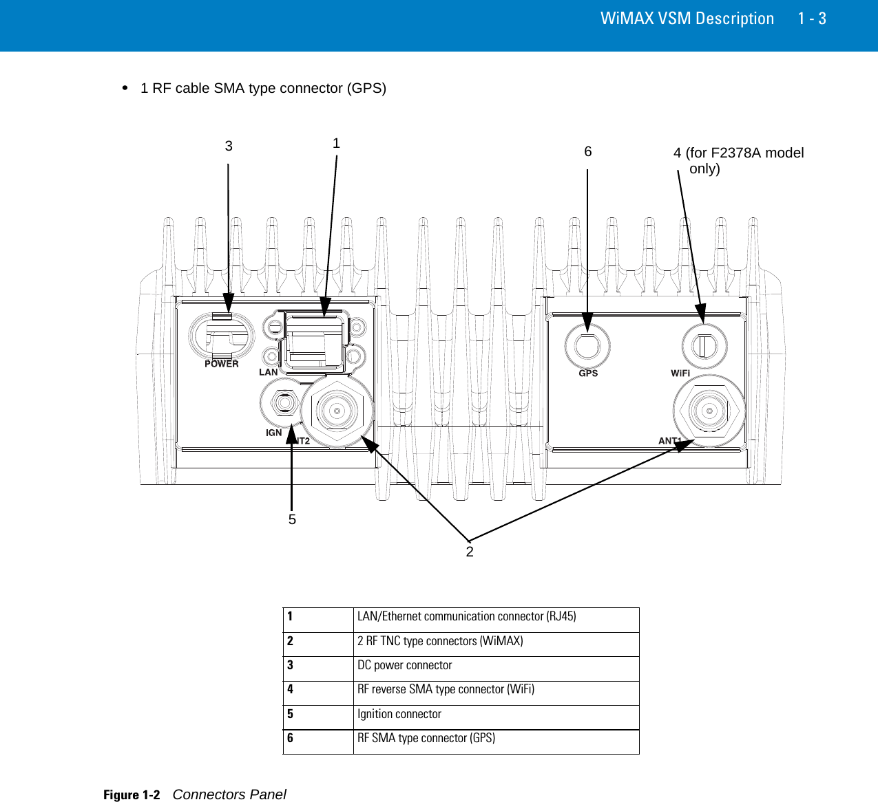
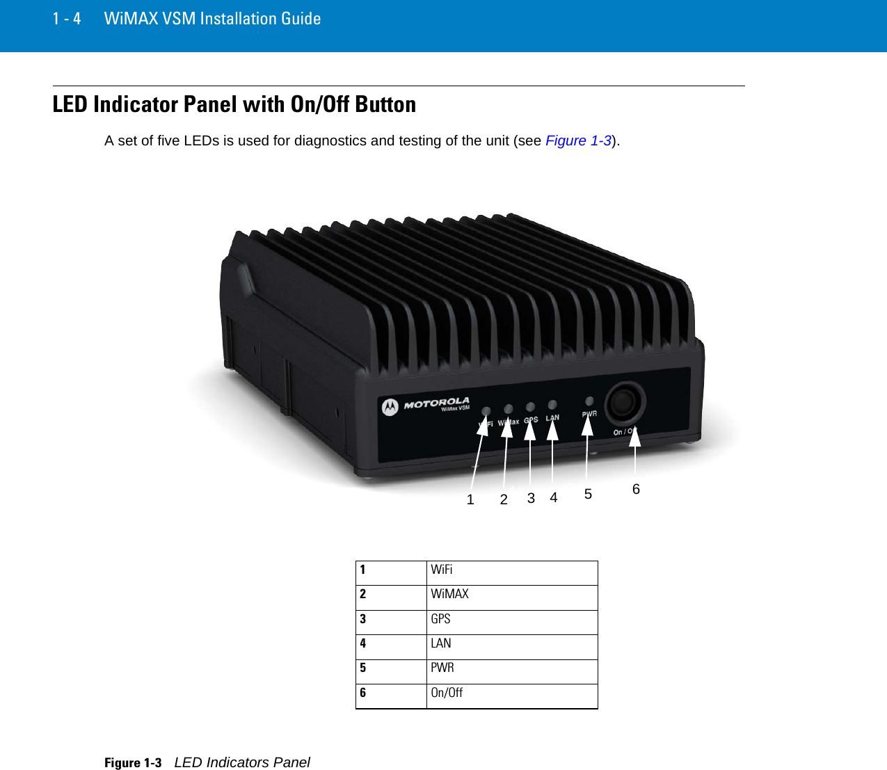
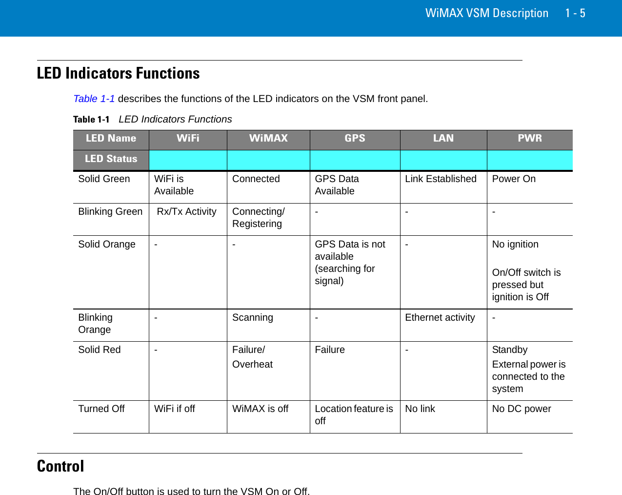
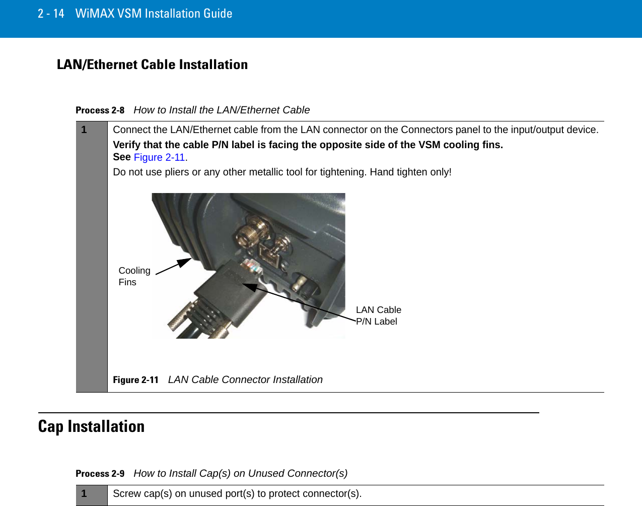
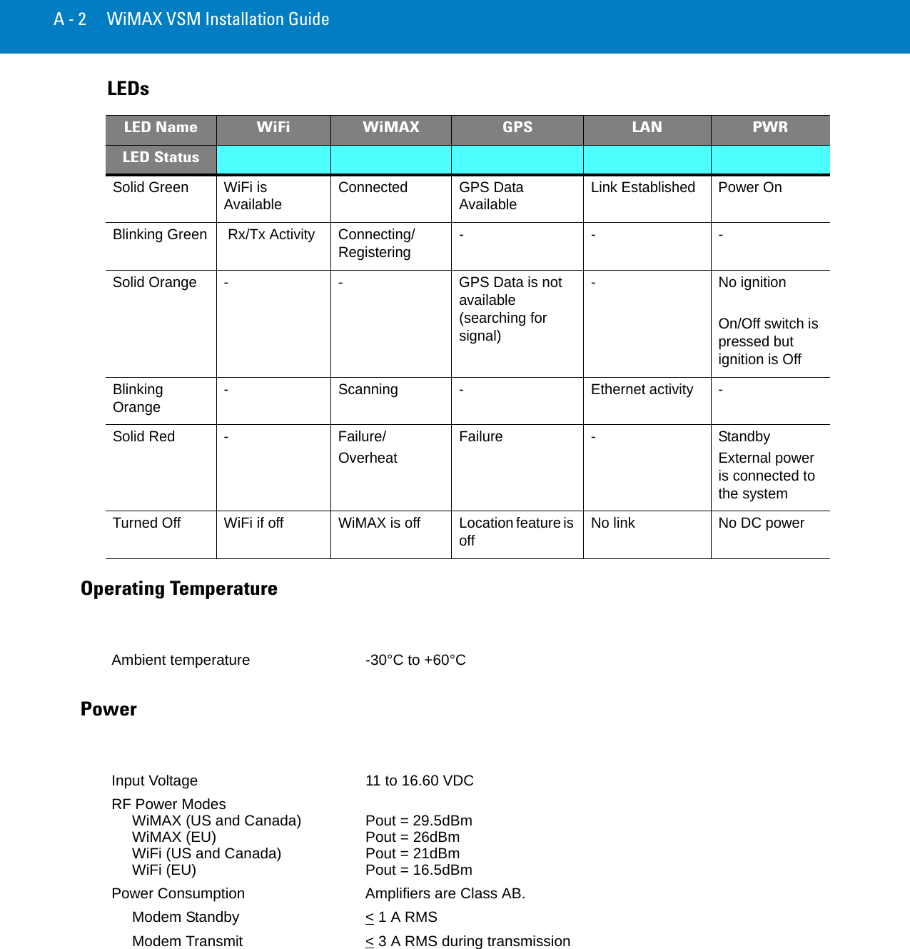
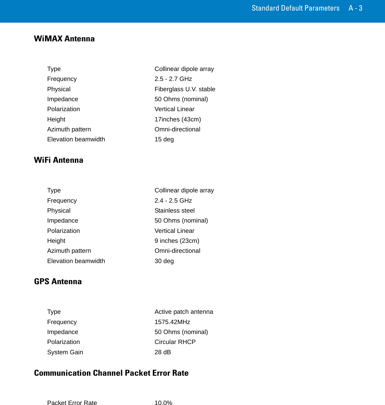
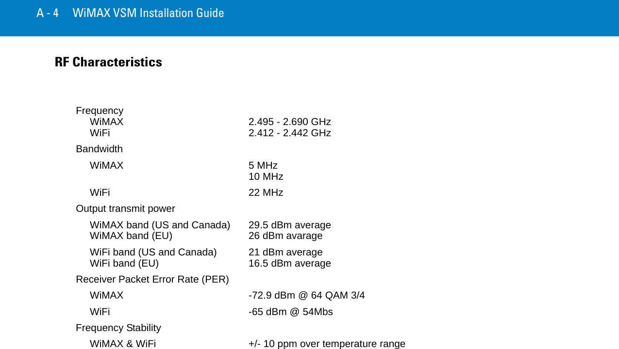
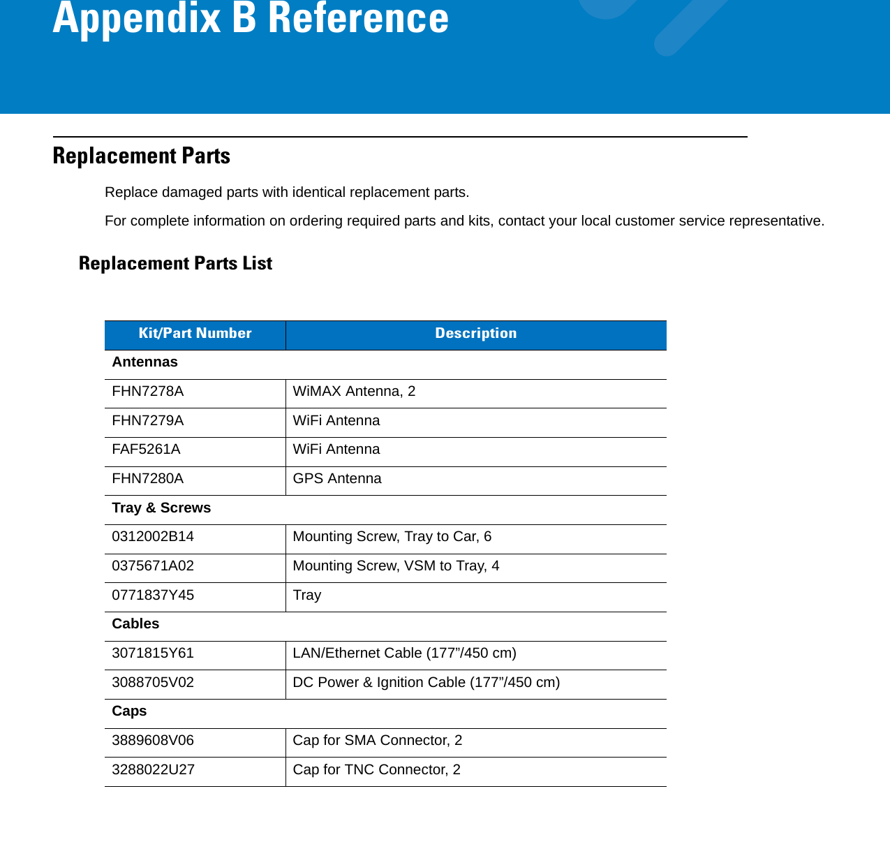
Exhibit 8 Users Manual