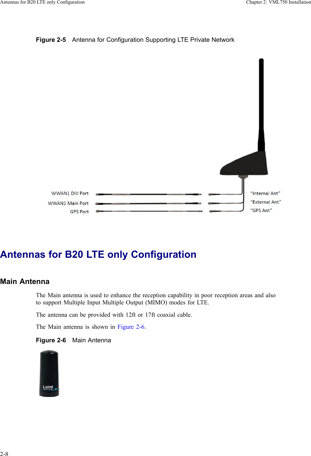
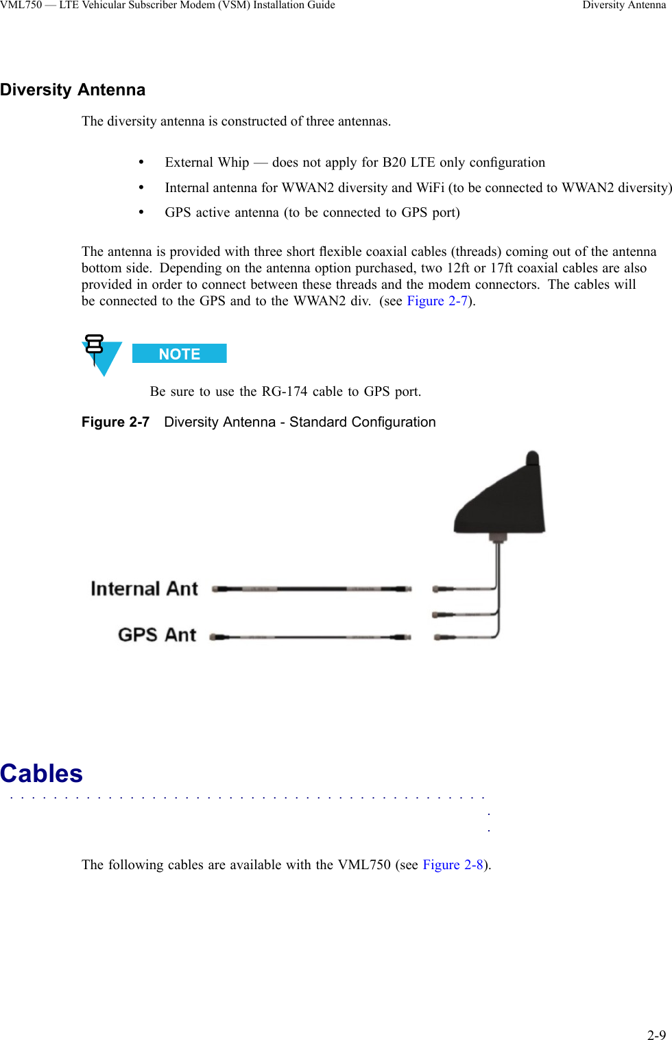
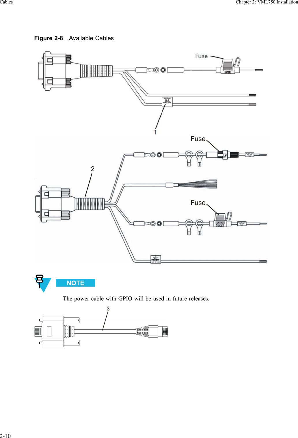
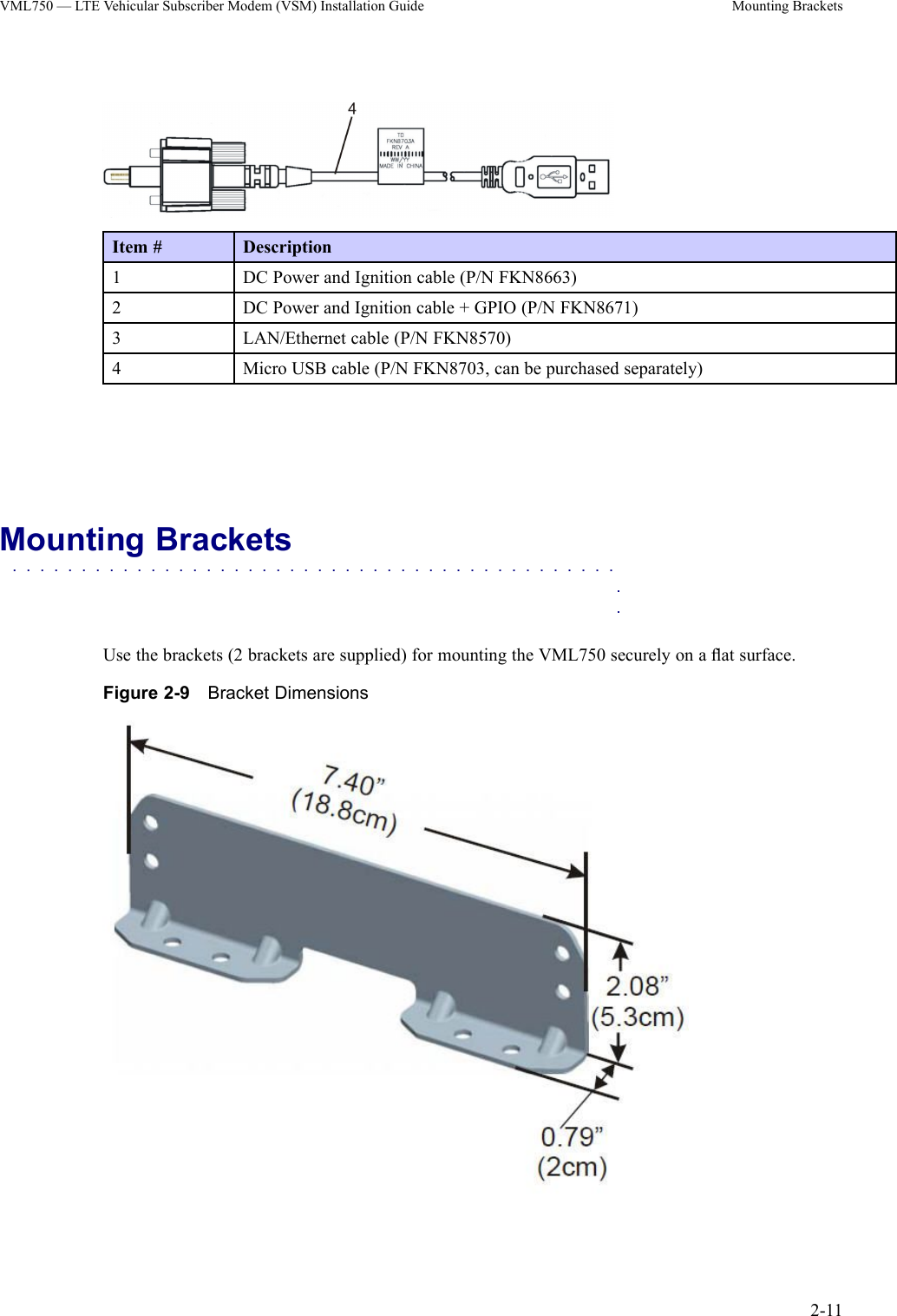
Motorola Solutions 92FT7058 VML750 RF Data Radio Modem User Manual
Motorola Solutions, Inc. VML750 RF Data Radio Modem
UserManual.wiki
>
Motorola Solutions
>
92FT7058 User Manual
>
User Manual
Contents
1.
User Manual
2.
User Manual Safety
3.
Manual
User Manual
Navigation menu
Upload a User Manual
Namespaces
Wiki Guide
HTML
PDF
Info
Views
User Manual
Discussion / Help
Navigation

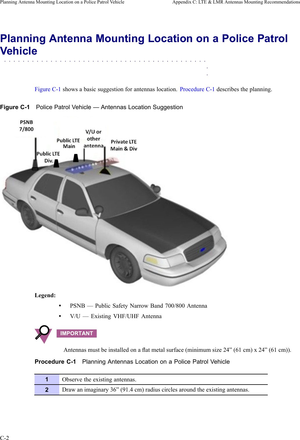
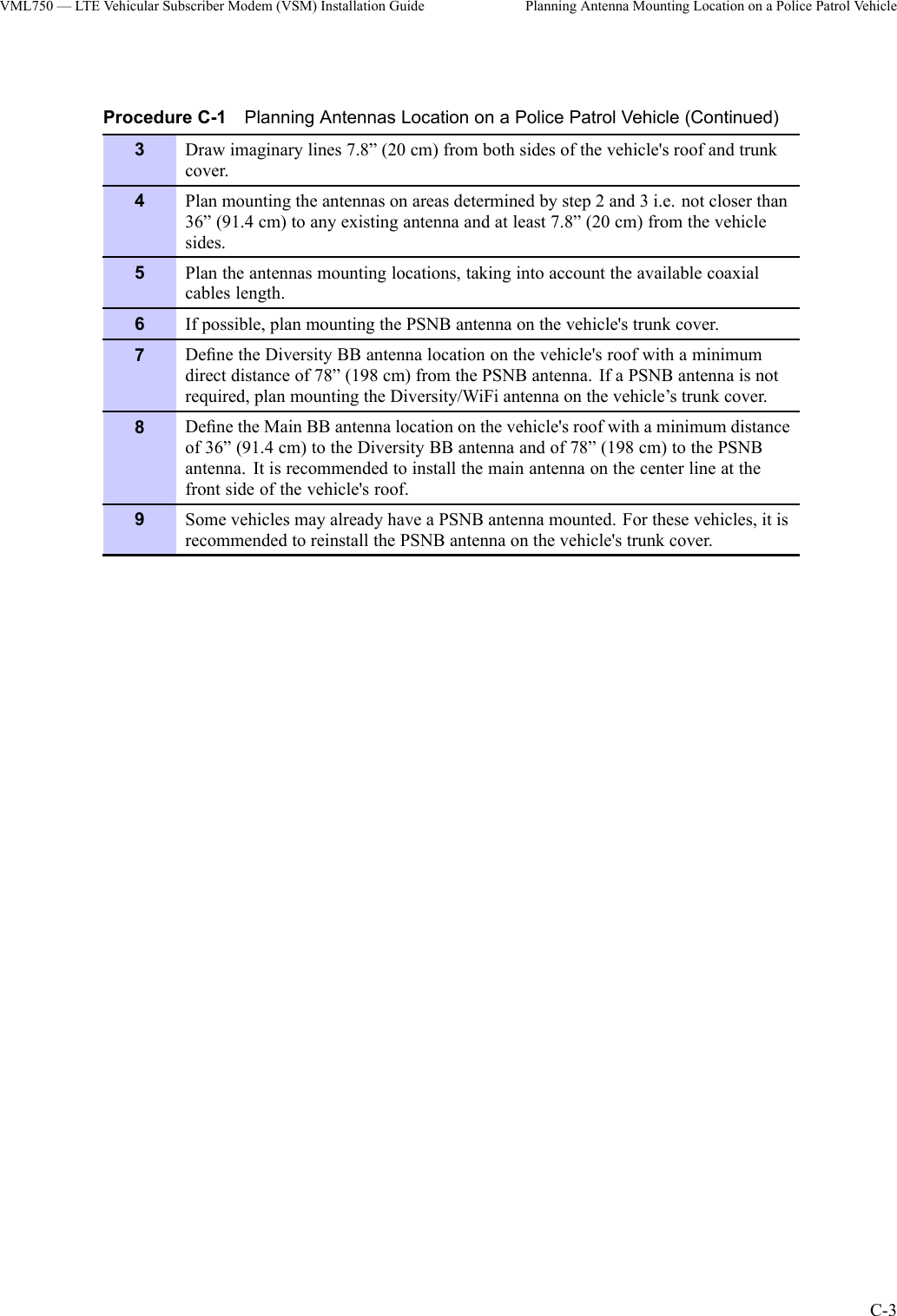
![AppendixCLTE&LMRAntennasMountingRecommendationsThisappendixprovidesproceduresfordeterminingthemountinglocationsforaPublicSafetyNarrowBand(PSNB)LMR700/800MHzantennaandBroadBand(BB)LTE700MHzantennas.Thefollowingproceduresaregiven:•PolicepatrolvehiclewithaPSNBantennaandastandardBBantenna.•BuswithaPSNBantennaandalowproleBBantennaPolicePatrolVehicleAntennasLocationConsiderations—Overview■■■■■■■■■■■■■■■■■■■■■■■■■■■■■■■■■■■■■■■■■■■■■■Theantennasmountinglocationisselectedindividuallyforeveryvehiclebeforestartingtheactualinstallationprocess.ThefollowinglistgivesgeneralrecommendationsfordeterminingthemountinglocationofPSNBandBBantennasbasedonseveralkeyconsiderations:•Keepaminimumdistanceof7.87”(20cm)betweentheLTE[BB]antennas;includingWiFitoanyotherantennaandanypotentialbystander(forbystandersafely).•FollowtheguidelinesintheinstallationandsafetymanualsoftheLMR[PSNB]radioswithregardstomountinglocationsandoperationofradiointhepresenceofbystanders(forbystandersafety).•Keepaminimumspatialseparationof78”(198cm)betweenthePSNBandBBLTEantennasthisseparationprovidesaminimumof35dBisolationtoreduceinterferences.•Keepaminimumspatialseparationof36”(91.4cm)betweenthetwoBBLTE(mainanddiversity)antennasforpotentialinterferencereductionandforoptimalMultipleInputMultipleOutput(MIMO)andMaximumRatiodiversityCombining(MRC)performance.6802988C54-BJuly2014C-1](https://usermanual.wiki/Motorola-Solutions/92FT7058.User-Manual/User-Guide-2598565-Page-65.png)