Motorola Solutions 92FT7079 Mobile 2-Way Radio User Manual NAG
Motorola Solutions, Inc. Mobile 2-Way Radio NAG
Contents
- 1. Manual
- 2. RF Safety Manual
- 3. Installation Manual
Installation Manual

-i
m
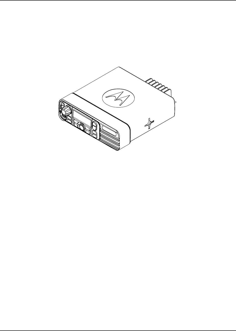
MOTOTRBO™ Mobile
Installation Guide
XPRTM 4350/XPRTM 4380 Numeric Display Mobile (with GPS)
XPRTM 4550/XPRTM 4580 Display Mobile (with GPS)
XPRTM 5350/XPRTM 5380 Numeric Display Mobile (with Bluetooth
and GPS)
XPRTM 5550/XPRTM 5580 Color Display Mobile (with Bluetooth
and GPS)
XPRTM 5350e/XPRTM 5380e Numeric Display Mobile (with WLAN,
Bluetooth and GPS)
XPRTM 5550e/XPRTM 5580e Color Display Mobile (with WLAN,
Bluetooth and GPS)
*6880309T23*
6880309T23-FA

0
i
Foreword
This manual is intended for use by experienced technicians familiar with similar types of equipment. Specifically, it contains
installation information required for the XPR Series Mobile Radios.
For information related to the service of the XPR Series Mobile Radios, refer to Related Publications on page v for the list
of applicable manuals available separately.
Product Safety and RF Exposure Compliance
See Installation Requirements for Compliance with Radio Frequency (RF) Energy Exposure Safety Standards on page ii.
Manual Revisions
Changes which occur after this manual is printed are described in PMRs (Publication Manual Revisions). These PMRs
provide complete replacement pages for all added, changed, and deleted items.
To obtain PMRs, go to:
https://businessonline.motorolasolutions.com
Parts Ordering
See Appendix A: Replacement Parts Ordering for information on how to obtain replacement parts. For part numbers, refer
to the service manuals listed in Related Publications on page v.
Computer Software Copyrights
The Motorola products described in this manual may include copyrighted Motorola computer programs stored in
semiconductor memories or other media. Laws in the United States and other countries preserve for Motorola certain
exclusive rights for copyrighted computer programs, including, but not limited to, the exclusive right to copy or reproduce in
any form the copyrighted computer program. Accordingly, any copyrighted Motorola computer programs contained in the
Motorola products described in this manual may not be copied, reproduced, modified, reverse-engineered, or distributed in
any manner without the express written permission of Motorola. Furthermore, the purchase of Motorola products shall not
be deemed to grant either directly or by implication, estoppel, or otherwise, any license under the copyrights, patents or
patent applications of Motorola, except for the normal non-exclusive license to use that arises by operation of law in the
sale of a product.
Document Copyrights
No duplication or distribution of this document or any portion thereof shall take place without the express written permission
of Motorola. No part of this manual may be reproduced, distributed, or transmitted in any form or by any means, electronic
or mechanical, for any purpose without the express written permission of Motorola.
Disclaimer
The information in this document is carefully examined, and is believed to be entirely reliable. However, no responsibility is
assumed for inaccuracies. Furthermore, Motorola reserves the right to make changes to any products herein to improve
readability, function, or design. Motorola does not assume any liability arising out of the applications or use of any product
or circuit described herein; nor does it cover any license under its patent rights nor the rights of others.
Trademarks
MOTOROLA, MOTO, MOTOROLA SOLUTIONS and the Stylized M logo are trademarks or registered trademarks of
Motorola Trademark Holdings, LLC and are used under license. All other trademarks are the property of their respective
owners.
© 2006 – 2015 Motorola Solutions, Inc. All rights reserved.

ii
Installation Requirements for Compliance with
Radio Frequency (RF) Energy Exposure Safety
Standards
ATTENTION!
This radio is intended for use in occupational/controlled conditions, where users have full knowledge
of their exposure and can exercise control over their exposure to meet FCC limits. This radio device is
NOT authorized for general population, consumer, or any other use.
To ensure compliance to RF Energy Safety Standards:
• Install only Motorola approved antennas and accessories.
• Be sure that antenna installation is per Antenna Installation on page 2-11 of this manual.
• Be sure that Product Safety and RF Safety Booklet enclosed with this radio is available to the end user
upon completion of the installation of this radio.
Before using this product, the operator must be familiar with the RF energy awareness information and
operating instructions in the Product Safety and RF Exposure booklet enclosed with each radio (Motorola
publication part number 6881095C99_) to ensure compliance with Radio Frequency (RF) energy exposure
limits.
This radio has a transmitter Time-out Timer that disables the transmitter during a transmission after a pre-
defined time period, which by default is set to 60 seconds.
For a list of Motorola-approved antennas and other accessories, visit the following web site, which lists
approved accessories for your radio model:
http://www.motorolasolutions.com
For radios installed in vehicles fuelled by liquefied petroleum gas, refer to the (U.S.) National Fire
Protection Association standard, NFPA58, for storage, handling, and/or container information.
It is recommended NOT to change the default 60 seconds time period for the Time-out Timer as the
radio is intended for intermittent duty cycle operation.
!
W A R N I N G
!
C a u t i o n

Table of Contents iii
Table of Contents
Foreword..........................................................................................................i
Product Safety and RF Exposure Compliance .............................................................................................i
Manual Revisions .........................................................................................................................................i
Parts Ordering ..............................................................................................................................................i
Computer Software Copyrights ....................................................................................................................i
Document Copyrights ...................................................................................................................................i
Disclaimer.....................................................................................................................................................i
Trademarks ..................................................................................................................................................i
Installation Requirements for Compliance with
Radio Frequency (RF) Energy Exposure Safety Standards.......................ii
Mobile Radio Model Numbering Scheme....................................................vi
Commercial Warranty .................................................................................viii
Limited Warranty ...................................................................................................................................... viii
MOTOROLA COMMUNICATION PRODUCTS.............................................................................. viii
I. What This Warranty Covers and For How Long.................................................................... viii
II. General Provisions .................................................................................................................ix
III. State Law Rights ...................................................................................................................ix
IV. How to Get Warranty Service ...............................................................................................ix
V. What This Warranty Does Not Cover.....................................................................................ix
VI. Patent and Software Provisions.............................................................................................x
VII. Governing Law......................................................................................................................x
Chapter 1 Introduction ......................................................................... 1-1
1.1 Mobile Radio Description............................................................................................................... 1-1
1.1.1 Overview .......................................................................................................................... 1-1
1.1.2 Dimensions ....................................................................................................................... 1-2
1.1.3 Connections on the Back of the Radio ............................................................................. 1-4
1.2 Standard Configurations ................................................................................................................ 1-5
1.2.1 Dash Mount Configuration ................................................................................................ 1-5
1.2.2 Remote Mount Configuration (XPR 4000/XPR 4000e Series Mobiles Only).................... 1-5
1.3 Base/Control Stations .................................................................................................................... 1-6
Chapter 2 Installation Details for Standard Configurations ............. 2-1
2.1 Planning the Installation................................................................................................................. 2-1
2.1.1 Tools Required for Installation .......................................................................................... 2-1
2.1.2 Installation Example.......................................................................................................... 2-1
2.1.3 Wiring Diagrams ............................................................................................................... 2-2
2.2 Radio Mounting ............................................................................................................................ 2-4
2.2.2 Locking Kit (Optional) ....................................................................................................... 2-6
2.2.2.1 All Radios................................................................................................................. 2-6
2.2.3 DIN Mount......................................................................................................................... 2-6
2.2.3.1 To install the frame into the dashboard ................................................................... 2-6
2.2.3.2 To Mount the radio in the frame............................................................................... 2-7
2.2.3.3 To Remove the radio from the frame....................................................................... 2-8
2.2.4 Remote Mount with Trunnion............................................................................................ 2-8
2.3 Power Cable .................................................................................................................................. 2-8

iv
2.4 Ignition Sense Cable.................................................................................................................... 2-11
2.5 Antenna Installation ..................................................................................................................... 2-11
2.5.1 Selecting an Antenna Site/Location on a Metal Body Vehicle ........................................ 2-11
2.5.2 Antenna Installation Procedure....................................................................................... 2-12
2.5.3 Antenna Connection ....................................................................................................... 2-13
2.6 Microphone Hang-Up Clip ........................................................................................................... 2-14
2.6.1 Standard Hang-Up Clip................................................................................................... 2-14
2.7 Completing the Installation .......................................................................................................... 2-14
Chapter 3 Options and Accessories Installation ............................... 3-1
3.1 Accessory Installation .................................................................................................................... 3-1
3.1.1 Emergency Pushbutton or Footswitch Installation ............................................................ 3-3
3.1.2 Horn and Lights (External Alarm) Relay ........................................................................... 3-4
3.1.3 External Speaker ............................................................................................................. 3-5
Chapter 4 Best Practices: Installation & Troubleshooting................ 4-1
4.1 Check Wiring of Ignition and Radio Ignition Sensing ..................................................................... 4-1
4.2 Check Physical Installation of Radio Ground and Radio Accessory Wiring................................... 4-2
4.3 Improve the Electrical Quality of the Power and Ignition Lines...................................................... 4-2
4.4 Jump-Start the Vehicle .................................................................................................................. 4-3
4.5 Eliminate Noise/Howling from PA Speaker.................................................................................... 4-3
Appendix A Replacement Parts Ordering............................................. A-1
A.1 Basic Ordering Information ............................................................................................................A-1
A.2 Motorola Online .............................................................................................................................A-1
A.3 Mail Orders ....................................................................................................................................A-1
A.5 Fax Orders.....................................................................................................................................A-2
A.6 Parts Identification .........................................................................................................................A-2
A.7 Product Customer Service.............................................................................................................A-2
Appendix B Motorola Service Centers .................................................. B-1
B.1 Servicing Information .....................................................................................................................B-1
B.2 Motorola Service Center ................................................................................................................B-1
B.3 Motorola Federal Technical Center ...............................................................................................B-1
B.4 Motorola Canadian Technical Logistics Center .............................................................................B-1
Index .....................................................................................................Index-1

List of Figures v
List of Figures
Figure 1-1 Front View of Dash Mount Trunnion for MOTOTRBO XPR 4000/XPR 4000e Series .......... 1-2
Figure 1-2 Front View of Dash Mount Trunnion for MOTOTRBOXPR 5000/XPR 5000e Series .......... 1-2
Figure 1-3 Side View of Dash Mount with Low Profile Trunnion for
MOTOTRBO XPR 4000/XPR 4000e Series ......................................................................... 1-3
Figure 1-4 Side View of Dash Mount with Low Profile Trunnion for
MOTOTRBO XPR 5000/XPR 5000e Series ......................................................................... 1-3
Figure 1-5 Back View of the Mobile Radio ............................................................................................. 1-4
Figure 1-6 Dash Mount Configuration .................................................................................................... 1-5
Figure 1-7 Example of a Base/Control Station Configuration................................................................. 1-6
Figure 2-1 Typical Dash Mount Configuration ........................................................................................ 2-1
Figure 2-2 Typical Remote Mount Configurations .................................................................................. 2-2
Figure 2-3 Radio Installation (Dash Mount)............................................................................................ 2-2
Figure 2-4 Radio Installation (Remote Mount) ....................................................................................... 2-3
Figure 2-5 Trunnion Orientation for Above or Below Mobile .................................................................. 2-4
Figure 2-6 Transmission Hump Trunnion Mounting ............................................................................... 2-5
Figure 2-7 Below Dash Trunnion Mounting ............................................................................................ 2-5
Figure 2-8 Locking Kit (Optional)............................................................................................................ 2-6
Figure 2-9 Dashboard Mounting for MOTOTRBO XPR 4000/XPR 4000e Series.................................. 2-7
Figure 2-10 Dashboard Mounting for MOTOTRBO XPR 5000/XPR 5000eSeries................................... 2-7
Figure 2-11 Cabling Interconnect Diagram for Dash Mount..................................................................... 2-9
Figure 2-12 Cabling Interconnect Diagram for Remote Mount............................................................... 2-10
Figure 2-13 Antenna connections on the back of the radio.................................................................... 2-12
Figure 2-14 Mini-UHF Connection ......................................................................................................... 2-13
Figure 3-1 Location of the Rear Accessory Connector .......................................................................... 3-1
Figure 3-2 Pin Configuration of Rear Accessory Connector (as viewed from the rear of the radio) ...... 3-2
Figure 3-3 Emergency Switch Wiring Diagram ...................................................................................... 3-3
Figure 3-4 Horn and Lights Wiring Diagram........................................................................................... 3-4
Figure 3-5 External Speaker Mounting................................................................................................... 3-5
Related Publications
MOTOTRBO XPR 4350/4550 Mobile Basic Service Manual .....................................................6880309T21_
MOTOTRBO XPR 4380/4580 Mobile Basic Service Manual ..................................................68009272001_
MOTOTRBO XPR 5350/5550 Mobile Basic Service Manual .................................................. 68009515001_
MOTOTRBO XPR 5580/5380 ............................................................................................. MN000305A01_
MOTOTRBO XPR 5000e Series Mobile Service Manual.......................................................MN002201A01_

vi Mobile Radio Model Numbering Scheme
Mobile Radio Model Numbering Scheme
Below is the model numbering scheme for XPR 5000e:
Below is the numbering scheme of XPR 4000 and 5000 series.
Model No.Example : AA M 2 8 J Q C 9 R A 1 A N
Position : 1 2 3 4 5 6 7 8 9 10 11 12
Unique Variations
N: Standard Package
Version Letter
Feature Level
1: Mini-U (Mobile)
2: BNC (Mobile)
Primary System Type
A: Conventional
B: Trunking
C: Analog Only
D: Limited System
E: Modified Conventional
Primary Operation
J: Basic (No GNSS, no Bluetooth)
K: GNSS (GPS or GLONASS) and Bluetooth
L: GPS only
M: Bluetooth only
R: GNSS, WiFi and Bluetooth
S: WiFi and Bluetooth only
V: Basic (No WiFi, No GNSS,
No Bluetooth, No embedded GOB)
W: GNSS only
Channel Information
9: Variable/Programmable
Channel Spacing
Power Level
N: 1–25 W
P: 25–40 W
Q: 25–45 W
R: 1–40 W
M: 10–35 W
MOTOTRBO Mobile
XPR 5000e Series : 28
Physical Packages
C: Numeric Display
H: Monochrome Display
N: Color Display
X: No Control Head
Mobile
AZ: Asia
LA: Latin America
AA: North America
MD: Europe
Band
J
M
K : 300–360 MHz
P
Q
T
X
U
V
: 136–174 MHz
: 217–222 MHz
: 350–400 MHz
: 403–470 MHz
: 450–527 MHz
: 450–520 MHz
: 806–941 MHz
: 806–870 MHz
Model No.Example : AA M 2 7 Q P H 9 L A 1 A N
Position : 1 2 3 4 5 6 7 8 9 10 11 12
Unique Model Variations
N: Standard Package
Version Letter
Feature Level
1: Mini-U
2: BNC
Primary System Type
A: Conventional
B: Trunking
C: Analog Only
Primary Operation
J: Basic (w/o Bluetooth or GPS)
K: w/ Bluetooth and GPS
L: w/ GPS Only
M: w/ Bluetooth Only
Channel Spacing
9: Variable/Programmable
Power Level
N: 1–25W
R: 1–40W
M: 10–35W
P: 25–40W
Q: 25–45W
Mobile Model Series
MOTOTRBO XPR 4000 Series: 27
MOTOTRBO XPR 5000 Series: 28
Band
J : 136–174 MHz
Q: 403–470 MHz
T : 450–527 MHz
X : 450–520 MHz
U : 806–941 MHz
Physical Packages
C: Numeric Display Model
H: Monochrome Display Model
(XPR 4000 Series)
N: Color Display Model
(XPR 5000 Series)
Mobile
A
Z: Asia
LA: Latin America
A
A: North America (except Mexico)
MD: Europe/Middle East/
Africa/Australasia

vii Mobile Radio Model Numbering Scheme
Notes
.
viii Commercial Warranty
Commercial Warranty
Limited Warranty
MOTOROLA COMMUNICATION PRODUCTS
I. What This Warranty Covers and For How Long
MOTOROLA INC. (“MOTOROLA”) warrants the MOTOROLA manufactured Communication
Products listed below (“Product”) against defects in material and workmanship under normal use and
service for a period of time from the date of purchase as scheduled below:
The mobiles additionally ship with a standard 1-year Repair Service Advantage (RSA) (for U.S.
customers) or 1-year Extended Warranty (for Canada customers). However, at the time of order, you
may choose to omit these warranties. For more RSA or Extended Warranty information, please refer
to the price pages or Motorola Online (https://businessonline.motorolasolutions.com) > Resource
Center > Services > Service Product Offerings > Repair Service Advantage or Extended Warranty.
Motorola, at its option, will at no charge either repair the Product (with new or reconditioned parts),
replace it (with a new or reconditioned Product), or refund the purchase price of the Product during
the warranty period provided it is returned in accordance with the terms of this warranty. Replaced
parts or boards are warranted for the balance of the original applicable warranty period. All replaced
parts of Product shall become the property of MOTOROLA.
This express limited warranty is extended by MOTOROLA to the original end user purchaser only and
is not assignable or transferable to any other party. This is the complete warranty for the Product
manufactured by MOTOROLA. MOTOROLA assumes no obligations or liability for additions or
modifications to this warranty unless made in writing and signed by an officer of MOTOROLA. Unless
made in a separate agreement between MOTOROLA and the original end user purchaser,
MOTOROLA does not warrant the installation, maintenance or service of the Product.
MOTOROLA cannot be responsible in any way for any ancillary equipment not furnished by
MOTOROLA which is attached to or used in connection with the Product, or for operation of the
Product with any ancillary equipment, and all such equipment is expressly excluded from this
warranty. Because each system which may use the Product is unique, MOTOROLA disclaims liability
for range, coverage, or operation of the system as a whole under this warranty.
XPR Series Mobile Radios Two (2) Years
Product Accessories One (1) Year

Commercial Warranty ix
II. General Provisions
This warranty sets forth the full extent of MOTOROLA'S responsibilities regarding the Product.
Repair, replacement or refund of the purchase price, at MOTOROLA's option, is the exclusive
remedy. THIS WARRANTY IS GIVEN IN LIEU OF ALL OTHER EXPRESS WARRANTIES. IMPLIED
WARRANTIES, INCLUDING WITHOUT LIMITATION, IMPLIED WARRANTIES OF
MERCHANTABILITY AND FITNESS FOR A PARTICULAR PURPOSE, ARE LIMITED TO THE
DURATION OF THIS LIMITED WARRANTY. IN NO EVENT SHALL MOTOROLA BE LIABLE FOR
DAMAGES IN EXCESS OF THE PURCHASE PRICE OF THE PRODUCT, FOR ANY LOSS OF
USE, LOSS OF TIME, INCONVENIENCE, COMMERCIAL LOSS, LOST PROFITS OR SAVINGS
OR OTHER INCIDENTAL, SPECIAL OR CONSEQUENTIAL DAMAGES ARISING OUT OF THE
USE OR INABILITY TO USE SUCH PRODUCT, TO THE FULL EXTENT SUCH MAY BE
DISCLAIMED BY LAW.
III. State Law Rights
SOME STATES DO NOT ALLOW THE EXCLUSION OR LIMITATION OF INCIDENTAL OR
CONSEQUENTIAL DAMAGES OR LIMITATION ON HOW LONG AN IMPLIED WARRANTY
LASTS, SO THE ABOVE LIMITATION OR EXCLUSIONS MAY NOT APPLY.
This warranty gives specific legal rights, and there may be other rights which may vary from state to
state.
IV. How to Get Warranty Service
You must provide proof of purchase (bearing the date of purchase and Product item serial number)
in order to receive warranty service and, also, deliver or send the Product item, transportation and
insurance prepaid, to an authorized warranty service location. Warranty service will be provided by
Motorola through one of its authorized warranty service locations. If you first contact the company
which sold you the Product, it can facilitate your obtaining warranty service. You can also call
Motorola at 1-888-567-7347 US/Canada.
V. What This Warranty Does Not Cover
A. Defects or damage resulting from use of the Product in other than its normal and customary
manner.
B. Defects or damage from misuse, accident, water, or neglect.
C. Defects or damage from improper testing, operation, maintenance, installation, alteration,
modification, or adjustment.
D. Breakage or damage to antennas unless caused directly by defects in material workmanship.
E. A Product subjected to unauthorized Product modifications, disassemblies or repairs
(including, without limitation, the addition to the Product of non-Motorola supplied equipment)
which adversely affect performance of the Product or interfere with Motorola's normal
warranty inspection and testing of the Product to verify any warranty claim.
F. Product which has had the serial number removed or made illegible.
G. Rechargeable batteries if:
- any of the seals on the battery enclosure of cells are broken or show evidence of
tampering.
- the damage or defect is caused by charging or using the battery in equipment or service
other than the Product for which it is specified.
H. Freight costs to the repair depot.

xCommercial Warranty
I. A Product which, due to illegal or unauthorized alteration of the software/firmware in the
Product, does not function in accordance with MOTOROLA’s published specifications or the
FCC type acceptance labeling in effect for the Product at the time the Product was initially
distributed from MOTOROLA.
J. Scratches or other cosmetic damage to Product surfaces that does not affect the operation of
the Product.
K. Normal and customary wear and tear.
VI. Patent and Software Provisions
MOTOROLA will defend, at its own expense, any suit brought against the end user purchaser to the
extent that it is based on a claim that the Product or parts infringe a United States patent, and
MOTOROLA will pay those costs and damages finally awarded against the end user purchaser in any
such suit which are attributable to any such claim, but such defense and payments are conditioned on
the following:
A. that MOTOROLA will be notified promptly in writing by such purchaser of any notice of such
claim;
B. that MOTOROLA will have sole control of the defense of such suit and all negotiations for its
settlement or compromise; and
C. should the Product or parts become, or in MOTOROLA's opinion be likely to become, the
subject of a claim of infringement of a United States patent, that such purchaser will permit
MOTOROLA, at its option and expense, either to procure for such purchaser the right to
continue using the Product or parts or to replace or modify the same so that it becomes
noninfringing or to grant such purchaser a credit for the Product or parts as depreciated and
accept its return. The depreciation will be an equal amount per year over the lifetime of the
Product or parts as established by MOTOROLA.
MOTOROLA will have no liability with respect to any claim of patent infringement which is based upon
the combination of the Product or parts furnished hereunder with software, apparatus or devices not
furnished by MOTOROLA, nor will MOTOROLA have any liability for the use of ancillary equipment or
software not furnished by MOTOROLA which is attached to or used in connection with the Product.
The foregoing states the entire liability of MOTOROLA with respect to infringement of patents by the
Product or any parts thereof.
Laws in the United States and other countries preserve for MOTOROLA certain exclusive rights for
copyrighted MOTOROLA software such as the exclusive rights to reproduce in copies and distribute
copies of such Motorola software. MOTOROLA software may be used in only the Product in which
the software was originally embodied and such software in such Product may not be replaced,
copied, distributed, modified in any way, or used to produce any derivative thereof. No other use
including, without limitation, alteration, modification, reproduction, distribution, or reverse engineering
of such MOTOROLA software or exercise of rights in such MOTOROLA software is permitted. No
license is granted by implication, estoppel or otherwise under MOTOROLA patent rights or
copyrights.
VII. Governing Law
This Warranty is governed by the laws of the State of Illinois, USA.

Chapter 1 Introduction
This manual covers the installation procedures for XPR Series Mobile Radios and accessories required
to complete the radio system. The radio system consists of a control head, radio, antenna,
microphone, speaker, cabling, and accessories.
1.1 Mobile Radio Description
1.1.1 Overview
Model Description
XPR 4300 Numeric Display model with 2 programmable buttons and a
2-character 7-segment display.
XPR 4350/
XPR 4380
Numeric Display model with 2 programmable buttons, a
2-character 7-segment display, and GPS.
XPR 4500 Display model with 4 programmable buttons and a dot-matrix
LCD.
XPR 4550/
XPR 4580
Display model with 4 programmable buttons, a dot-matrix
LCD, and GPS.
XPR 5350 Numeric Display model with 4 programmable buttons, a 2-
character 7-segment display, Bluetooth, and GPS.
XPR 5550 Colour Display model with 4 programmable buttons, a colour
LCD, Bluetooth, and GPS.
XPR 5580 Colour Display model with 4 programmable buttons, a colour
LCD, Bluetooth, and GPS.
XPR 5380 Numeric Display model with 4 programmable buttons, a 2-
character 7-segment display, Bluetooth, and GPS.
XPR 5350e Numeric Display model with 4 programmable buttons, a 2-
character 7-segment display, WLAN, Bluetooth, and GPS.
XPR 5550e Color Display model with 4 programmable buttons, a color
LCD, WLAN, Bluetooth, and GPS.
XPR 5580e Color Display model with 4 programmable buttons, a color
LCD, WLAN, Bluetooth, and GPS.
XPR 5380e Numeric Display model with 4 programmable buttons, a 2-
character 7-segment display, WLAN, Bluetooth, and GPS.
1-2 Introduction Mobile Radio Description
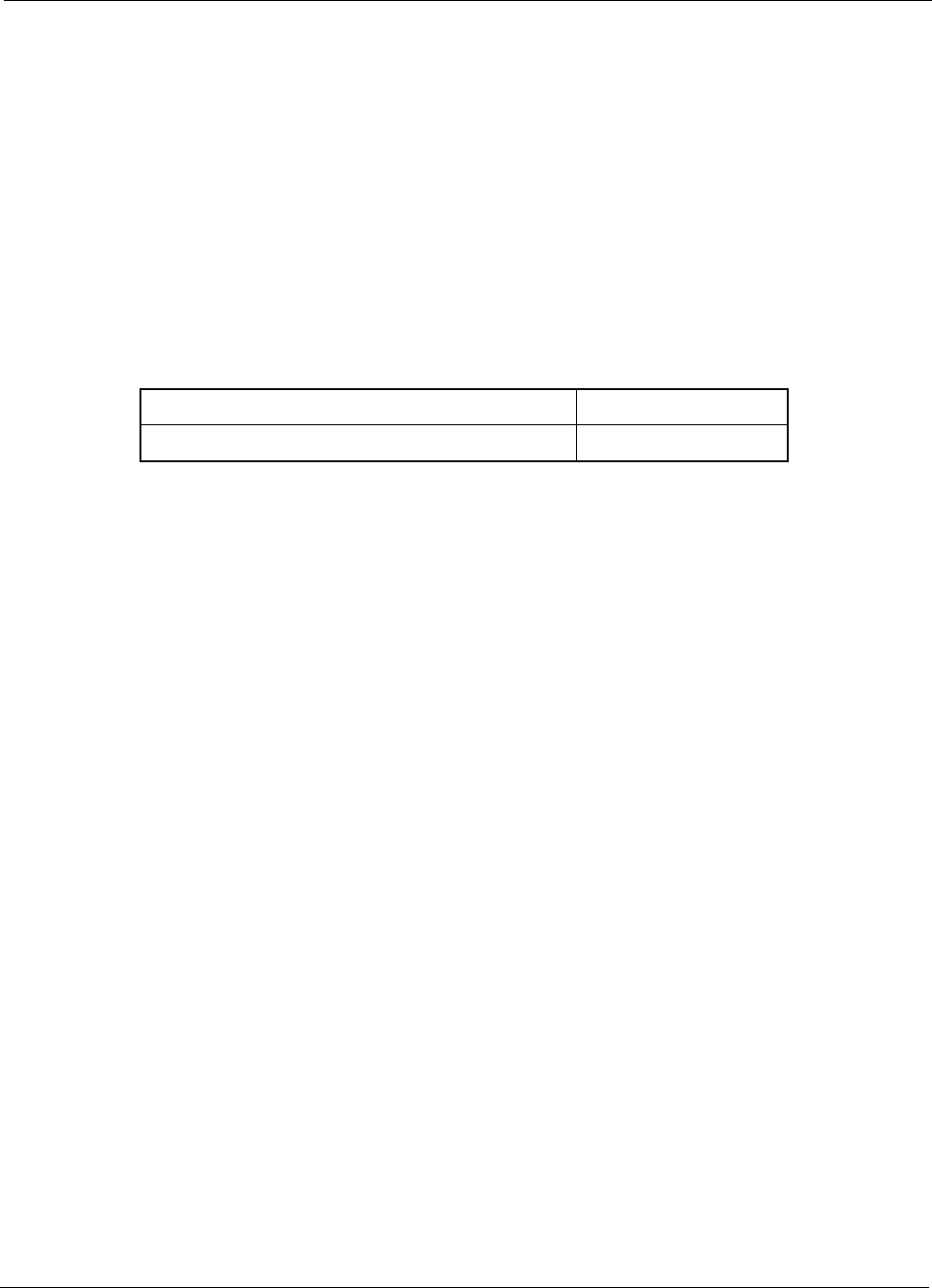
1.1.2 Dimensions
Figure 1-1, Figure 1-2, Figure 1-3 and Figure 1-4 show the basic dimensions of the dash mount
trunnion of the mobile radio.
When installing the radio, make sure to plan the installation carefully and leave additional room in the
rear of the radio for cabling and accessory connections; in the front of the radio for access, controls,
and cabling; and to the sides of the radio so that you may access and install the trunnion wing
screws.
Figure 1-1 Front View of Dash Mount Trunnion for MOTOTRBO XPR 4000/
XPR 4000e Series
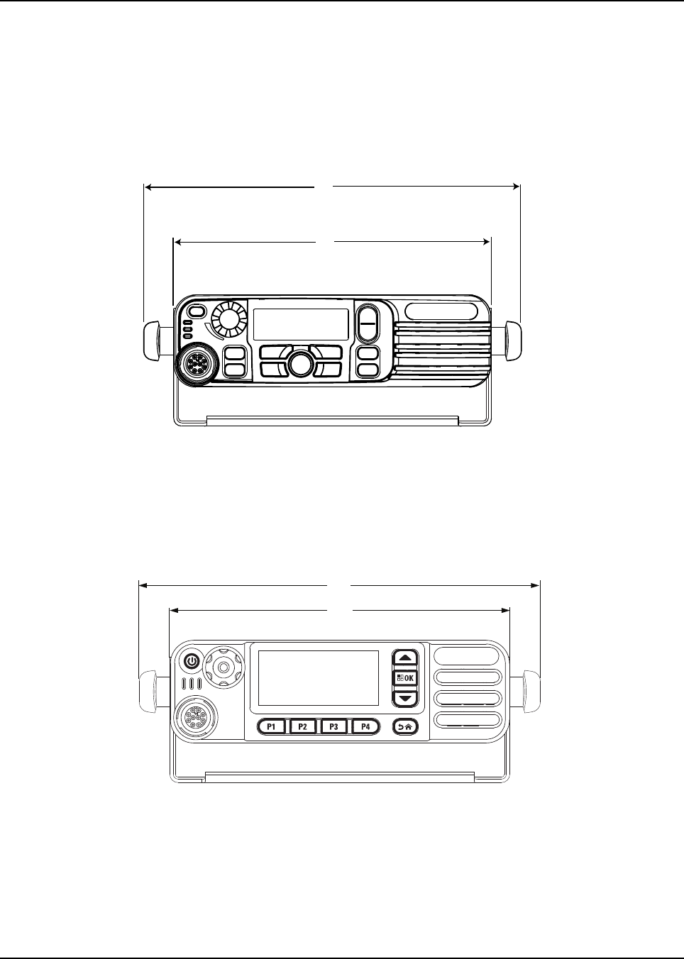
Figure 1-2 Front View of Dash Mount Trunnion for MOTOTRBOXPR 5000/
XPR 5000e Series
8.2”
6.8”
6.9”
8.2”
Introduction Mobile Radio Description 1-3
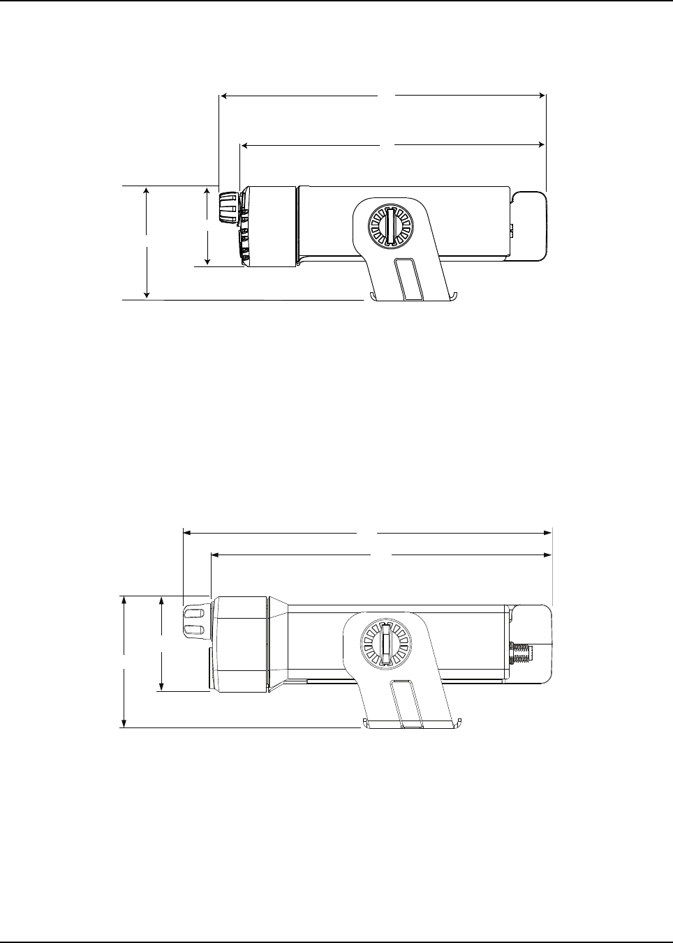
Figure 1-3 Side View of Dash Mount with Low Profile Trunnion for
MOTOTRBO XPR 4000/XPR 4000e Series
NOTE: The MOTOTRBO XPR 4000/XPR 4000e Series mobile models use wing screws with thread
length of 14.9 mm while the XPR 5000/XPR 5000eSeries models require wing screws with
thread length of 9.9 mm to secure the radio to the mounting trunnion.
NOTE: The rear accessory connector adds 0.75 in (19.1 mm) to the overall length.
Figure 1-4 Side View of Dash Mount with Low Profile Trunnion for
MOTOTRBO XPR 5000/XPR 5000e Series
8.3”
7.9”
2“
2.4“
7.4”
8.1”
2.5”
2.1”
1-4 Introduction Mobile Radio Description
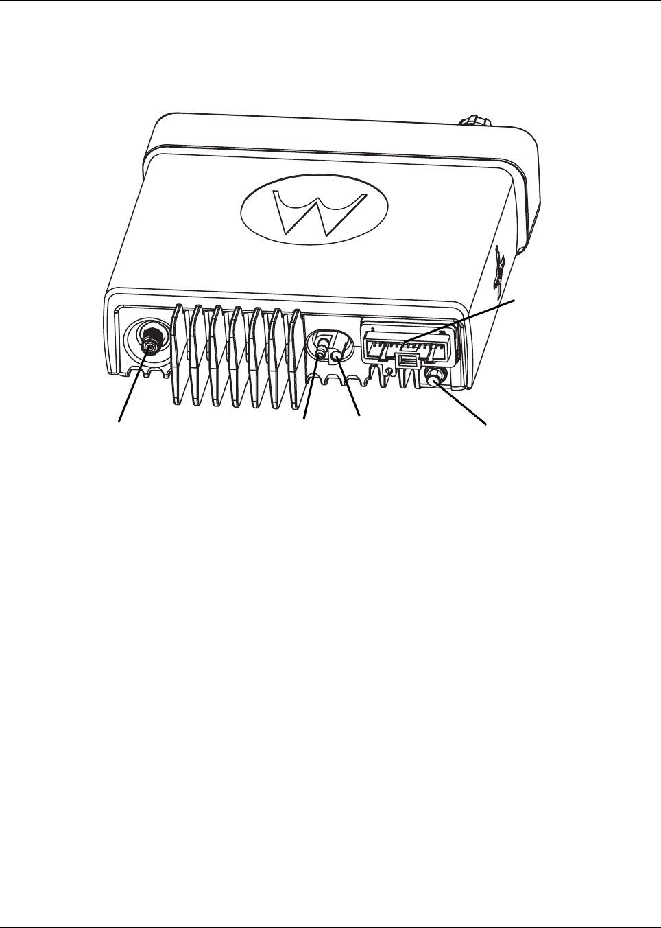
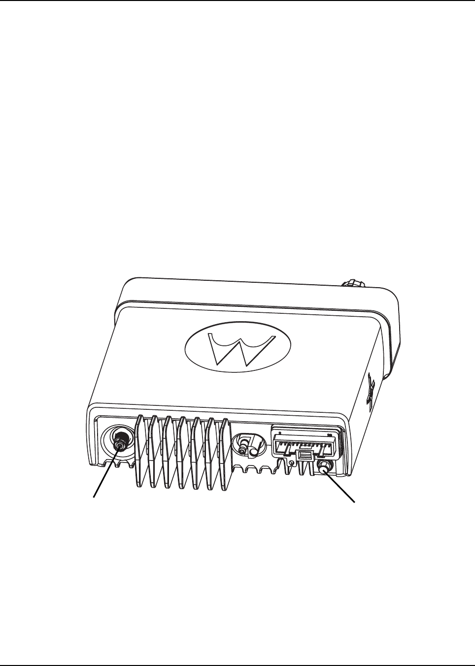
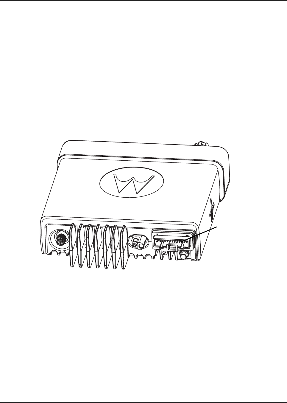
1.1.3 Connections on the Back of the Radio
Figure 1-5 shows the connections that are found on the back of the radio.
For complete pin configuration of the rear accessory connector, see Figure 3-2 on page 3-2.
Figure 1-5 Back View of the Mobile Radio
Antenna Connector Battery+ Battery- GPS-Antenna
Connector
Rear Accessory
Connector
Introduction Standard Configurations 1-5
1.2 Standard Configurations
The XPR 4000/XPR 4000e Series mobile can be either dash mounted or remote mounted. The XPR
5000/XPR 5000e Series mobile can only be dash mounted at this time.
1.2.1 Dash Mount Configuration
In the dash mount configuration of the mobile radio, the control head is mounted on the front of the
transceiver housing. Electrical connection between the two takes place within the radio via a flexible
cable between the connectors on the front of the transceiver and at the back of the control head.
Figure 1-6 Dash Mount Configuration
For details on this configuration, see Section 2.2.1 on page 2-5.
1.2.2 Remote Mount Configuration (XPR 4000/XPR 4000e Series Mobiles Only)
In the remote control version, the control head and the transceiver are mounted separately in the
vehicle. The control head is mounted in a remote trunnion (PMLN4912_) near the operator using an
extension cable. The transceiver is mounted using one of the trunnion mounting options shown in
Table 2-1 on page 2-4. If the transceiver is located in a car trunk, be sure that secure mounting and
sufficient cooling are provided. Do not cover the transceiver with baggage, blankets, etc.
See publication 6878397A01 for the MOTOTRBO XPR 4000/XPR 4000e Series Mobile Radio
remote mount control head installation instructions.
1-6 Introduction Base/Control Stations
1.3 Base/Control Stations
If the mobile radio equipment is installed at a fixed location and operated as a control station or as a
fixed unit, the radio and antenna installation must comply with the following requirements in order to
ensure optimal performance and compliance with the RF energy exposure limits in the standards
and guidelines listed in the Safety Booklet (Motorola publication part number 68P81095C99_)
provided with the radio:
• The antenna should be mounted outside the building on the roof or a tower if at all possible and
the antenna cable should be earth grounded.
• The radio chassis must be earth grounded and a lightning surge protector should be used in
line with the radio connector and the outdoor antenna. The lightning surge protector should be
earth grounded and located at the point where the antenna cable enters the building.
• The line voltage power supply must have a proper ground connection.
• As with all fixed site antenna installations, it is the responsibility of the licensee to manage the
site in accordance with applicable regulatory requirements. Also, additional compliance actions
such as site survey measurements, signage, and site access restrictions may be required in
order to ensure that exposure limits are not exceeded.
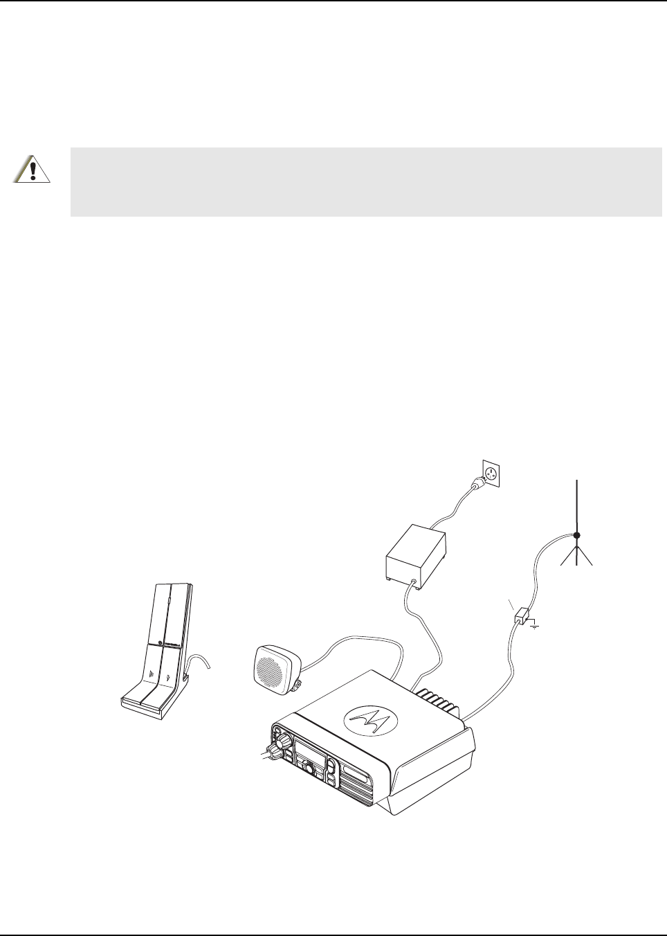
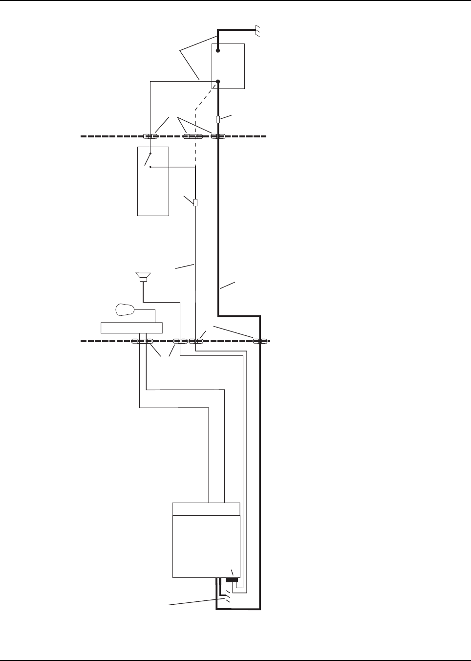
Figure 1-7 shows a typical setup of a Base/Control Station configuration.
Figure 1-7 Example of a Base/Control Station Configuration
For outdoor antenna installations, proper site grounding and lightning protection are vitally important.
Failure to provide proper lightning protection may result in permanent damage to the radio equipment.
Refer to Motorola Quality Standards Fixed Network Equipment Installation Manual R56 (which can be
obtained by ordering CDROM 9880384V83) for complete information regarding lightning protection.
C a u t i o n
C
C
C
C
C
C
C
C
C
C
C
C
C
C
C
C
C
C
C
C
C
C
C
C
C
C
C
C
C
C
C
C
CC
C
C
Speaker
Desk
Microphone
Power Supply
Wall-
outlet
Radio in
Desktop Tray
Line Cord
with Ground
Desktop
Power Cable
Antenna
Cable
Antenna Connector
Outdoor Antenna
Lightning Protector With
Quarter Wave Shorting Stub
Chapter 2 Installation Details for Standard
Configurations
2.1 Planning the Installation
The mobile radio operates only in negative ground electrical systems. Before starting the radio
installation, make sure that the ground polarity of the vehicle is correct. Accidentally reversing the
polarity will not damage the radio, but will cause the cable fuses to blow.
Planning is the key to fast, easy radio installation. Before starting the installation, inspect the vehicle
and determine how and where you intend to mount the antenna, radio, and accessories. Plan wire
and cable runs to provide maximum protection from pinching, crushing, and overheating.
2.1.1 Tools Required for Installation
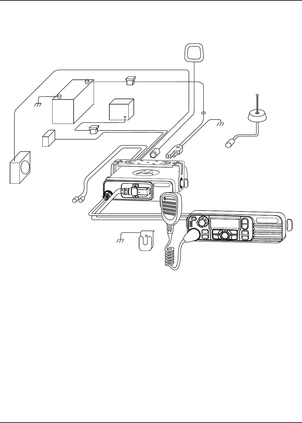
2.1.2 Installation Example
The mobile two-way radio offers various methods of installation, with accessories placed to the
vehicle as desired. The radio can be a dash or remote mount (XPR 5000/XPR 5000e Series models
can only be dash mounted). (See Figure 2-1 and Figure 2-2).
Before installing any electrical equipment, check the vehicle manufacturer’s user manual. The installation
of this device should be completed by an authorized servicer or installer.
Tool Motorola Part
Number
11/32 hex driver —
Rubber-coated pliers —
Regular slot screwdriver or
Phillips #2 —
Pin removal tool 6680163F01
1/4 hex driver —
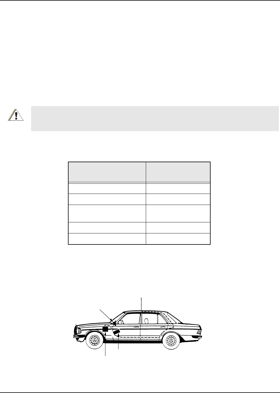
Figure 2-1 Typical Dash Mount Configuration
C a u t i o n
Radio
Antenna
1/4-Wavelength
Battery
Speaker
2-2 Installation Details for Standard Configurations Planning the Installation
2.1.3 Wiring Diagrams
Figure 2-3 shows the wiring diagrams for some of the possible configurations. Identify the
configuration that you are installing, and use the diagram when planning the installation.
Figure 2-3 Radio Installation (Dash Mount)
(For complete rear accessory connector pin configuration, see Figure 3-2.)
Figure 2-2 Typical Remote Mount Configurations
Antenna ¼ - Wavelength
Radio
Control
Head
Battery
Control
Head
Speaker
BATTERY
HORN/
LIGHT
MIC
CLIP
SPEAKER
MIC
EMERGENCY
SWITCH
FUSE
FUSE
BLOCK
(+)
(-) RED LEAD
FUSE
FIREWALL
HOLE
CONTROL HEAD
ANTENNA
CONNECTION
RF ANTENNA
GPS
ANTENNA
IGNITION CABLE
DC
POWER
CABLE
TRUNNION
Installation Details for Standard Configurations Planning the Installation 2-3
Figure 2-4 Radio Installation (Remote Mount)
(For complete rear accessory connector pin configuration, see Figure 3-2.)
BATTERY
HORN/
LIGHT
MIC
CLIP
SPEAKER
MIC
EMERGENCY
SWITCH
FUSE
FUSE
BLOCK
(+)
(-)
RED LEAD
FUSE
FIREWALL
HOLE
CONTROL HEAD
ANTENNA
CONNECTION
RF ANTENNA
GPS
ANTENNA
IGNITION CABLE
DC
POWER
CABLE
TRUNNION
2-4 Installation Details for Standard Configurations Radio Mounting
2.2 Radio Mounting
The mounting location must be accessible and visible. Select a location that will permit routing the
RF antenna cable as directly as possible.
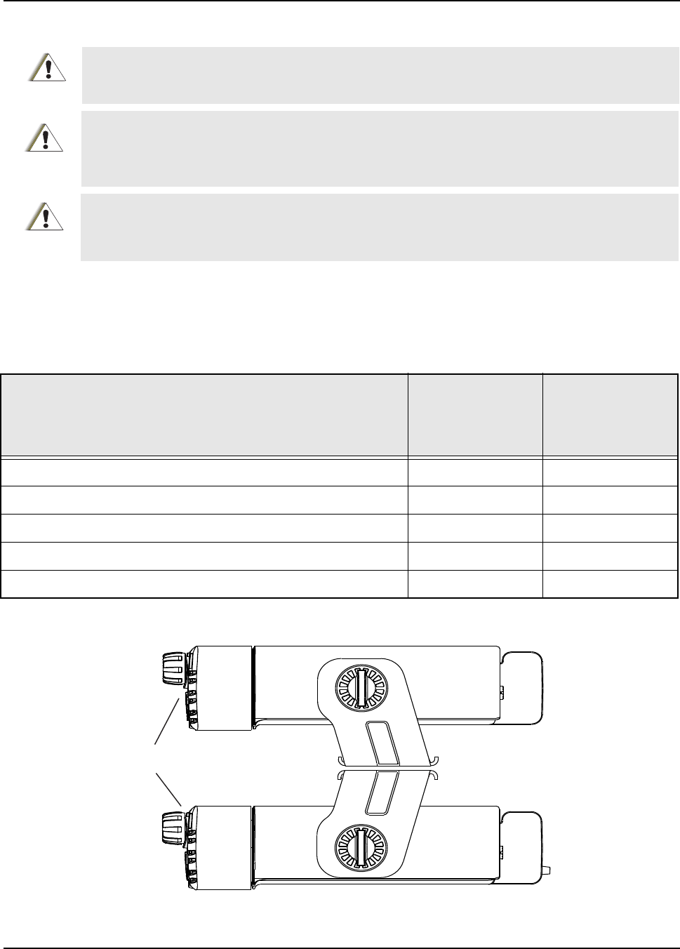
For new or existing installations, use one of the mounting kits as specified in Table 2-1. Orient the
mounting trunnion as shown in Figure 2-5.
Figure 2-5 Trunnion Orientation for Above or Below Mobile
DO NOT mount the radio on a plastic dashboard without first reinforcing the dashboard; the weight of
the radio may crack or break the dashboard.
DO NOT mount the radio on a flat or concave surface where the radio could be partially submersed in
water. This is especially important if the cab area of the vehicle is cleaned by spraying with water. If the
radio sits in water for a length of time, moisture may seep inside the radio and damage the electronic
components.
DO NOT allow water to stand in recessed areas of vertically mounted radios. Remove any moisture
immediately to prevent it from seeping down into the radio.
Table 2-1. Mounting Kits
Mounting Kit
Motorola Part
Number for XPR
4000/XPR 4000e
Series
Motorola Part
Number for XPR
5000/XPR 5000e
Series
Low Profile Trunnion Kit (ships as part of mobile radio package) RLN6076_ RLN6469_
Low Profile Trunnion Kit (ships in a box – intended for resale) RLN6077_ RLN6466_
Standard Profile Trunnion Kit RLN6078_ RLN6467_
Key Lock Trunnion Kit RLN6079_ RLN6468_
DIN Mount Kit RLN5933_ RLN6465_
C a u t i o n
C a u t i o n
C a u t i o n
RADIO
FRONT
Installation Details for Standard Configurations Radio Mounting 2-5
2.2.1 Dash Mount with Trunnion
1. Select the location to mount your radio on the transmission hump (see Figure 2-6) or under
the dash (see Figure 2-7). When mounting the trunnion on the transmission hump take care
the transmission housing is not affected.
2. Using the trunnion mounting bracket as a template, mark the positions of the holes on the
mounting surface. Use the innermost four holes for a curved mounting surface such as the
transmission hump, and the four outermost holes for a flat surface such as under the dash.
3. Center punch the spots you have marked and realign the trunnion in position.
4. Secure the trunnion mounting bracket with the self-drilling screws provided. The number of
screws used will depend on how the radio is mounted (see Figure 2-6 and Figure 2-7).
5. Position the radio to align the trunnion with the trunnion mounting features on the radio (see
Figure 2-6). Secure the radio with the two wing screws and lock washers (position the flat
side of the washer to the thumbscrew and the washer sharp side to the trunnion) provided.
Figure 2-6 Transmission Hump Trunnion Mounting
Figure 2-7 Below Dash Trunnion Mounting
Wing Screw
Trunnion
Wing Screw
Threaded Hole
for Wing Screw
Tab s
Lock Washer
Lock Washer
Trunnion
Wing Screw
Wing Screw
Lock Washer
Lock Washer
2-6 Installation Details for Standard Configurations Radio Mounting
2.2.2 Locking Kit (Optional)
2.2.2.1 All Radios
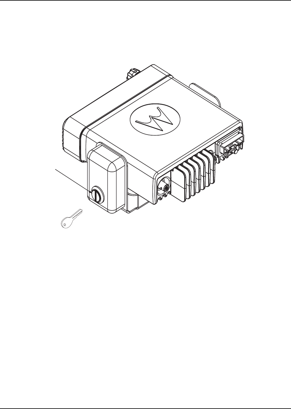
If an optional locking kit is used (shown in Figure 2-8), position the lock bottom housing on the
trunnion before installing the radio mounting screws. Then slip the top lock housing on and remove
the key. You can install the lock on either side of the radio.
Figure 2-8 Locking Kit (Optional)
2.2.3 DIN Mount
2.2.3.1 To install the frame into the dashboard
1. Open up the radio cut-out in the dashboard to ISO7736 specification (182 mm x 53 mm).
2. Insert the mounting frame into the cut-out and retain it by bending back the relevant fixing
tabs (using all 6 where possible). Check the orientation of the frame is correct by ensuring
that the word “TOP” is uppermost.
NOTE: The tabs are easily bent back by twisting a large flat-head screwdriver in the slot behind the
tabs.
NOTE: For a more secure installation the frame should also be secured with the appropriate number
of screws to the mounting conditions (min. 1).
NOTE: The demounting tool can be used as an aid to mounting as well as demounting.
Lock
Installation Details for Standard Configurations Radio Mounting 2-7
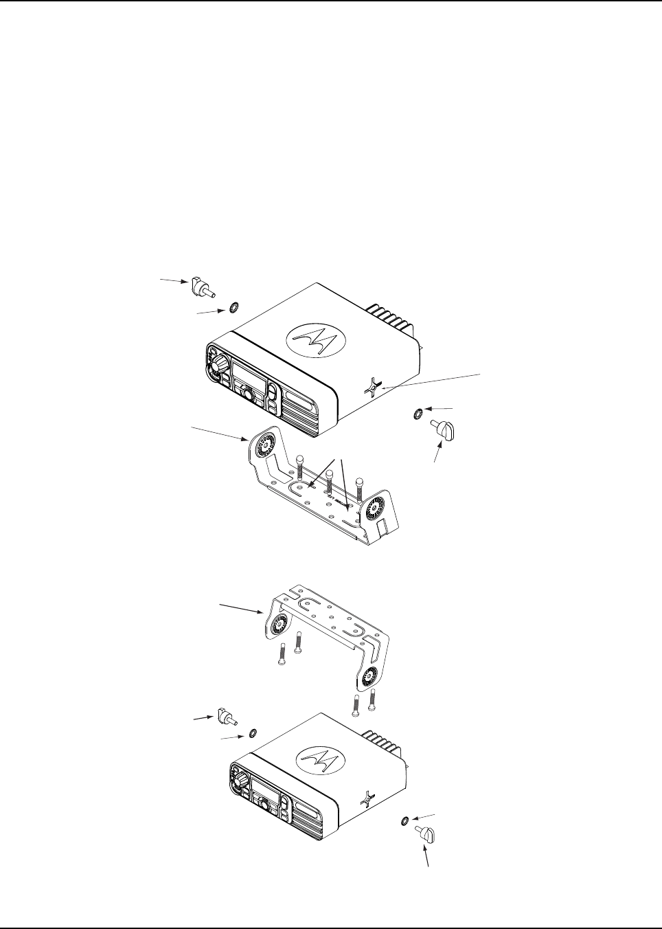
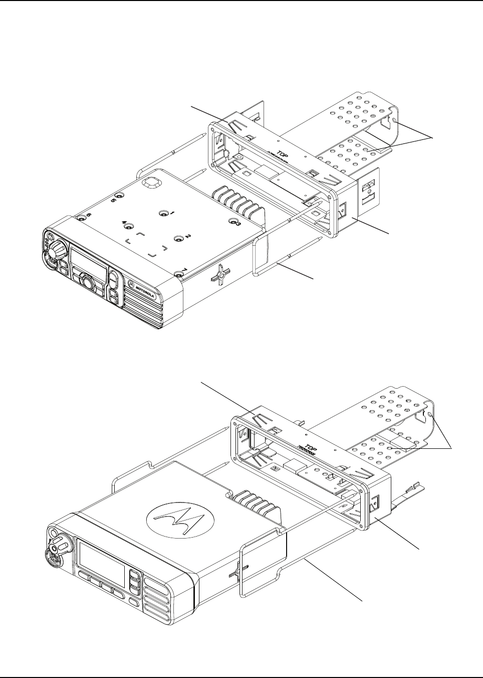
2.2.3.2 To Mount the radio in the frame
1. Provide the electrical connections for the radio (power, antenna, accessories).
2. Plug in all the connectors and push the radio firmly into the mounting frame until the two
springs snap into place (shown in Figure 2-9).
Figure 2-9 Dashboard Mounting for MOTOTRBO XPR 4000/XPR 4000e Series
Figure 2-10 Dashboard Mounting for MOTOTRBO XPR 5000/XPR 5000eSeries
Demounting Tool
Fix screws
here to secure
frame
Fixing
Tabs
DIN Mount
RLN5933_
DIN Mount
RLN6465_
Demounting Tool
Fix screws
here to secure
frame
Fixing
Tabs

2-8 Installation Details for Standard Configurations Power Cable
2.2.3.3 To Remove the radio from the frame
1. Push the two demounting tools through the openings in the frame until the two springs
release the radio.
2. Slide out the radio.
NOTE: The fixing tabs should be checked for tightness each time the radio is removed. The tabs are
easily tightened by twisting a large flat-head screwdriver in the slot behind the tabs.
NOTE: The frame is not designed for regular mounting and demounting.
2.2.4 Remote Mount with Trunnion
For a remote mount installation, the transceiver may be mounted anywhere in the vehicle, provided
that the installation location is safe, follows the cautions mentioned at the beginning of this section,
and is accessible for servicing/maintenance as well as cabling. A typical mounting location
recommended by Motorola is the vehicle’s trunk. The trunnion provided may still be used to mount
the transceiver, and the mounting process is the same as for the dash mount installation.
See publication 6878397A01 for the MOTOTRBO XPR 4000/XPR 4000e Series mobile radio remote
mount control head installation instructions.
2.3 Power Cable
Route the red radio power cable from the radio to the vehicle’s battery compartment, using accepted
industry methods and standards. Be sure to grommet the firewall hole to protect the cable. Remove
the 15-Amp (part number 6580283E06) or 20-Amp (part number 6580283E07) fuse from the
fuseholder and connect the red lead of the radio power cable to the positive battery terminal using
the hardware provided as shown in Figure 2-12. Connect the black lead to a convenient solid
chassis ground point. DO NOT connect the black lead directly to the battery’s negative terminal.
Before installing any electrical equipment, check the vehicle manufacturer’s user
manual.
The installation of this device should be completed by an authorized servicer or
installer.
Before making any holes in the trunk for radio mounting, check the vehicle
manufacturer’s user manual for restrictions (e.g. due to the gas tank location).
C a u t i o n

Installation Details for Standard Configurations Power Cable 2-9
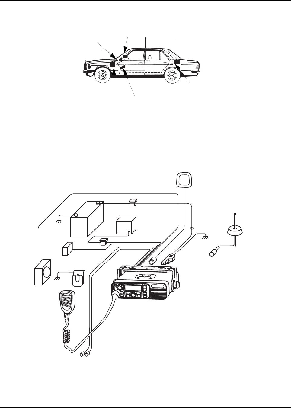
RADIO COMPARTMENT = OPERATOR COMPARTMENT VEHICLE BATTERY
COMPARTMENT
A good chassis connection via the black primary
power cable is essential for radio operation and
to prevent damage to the radio and cable kit.
Connection to the vehicle frame is desirable.
VEHICLE
BATTERY
15A OR 20A
FUSE
PART OF
VEHICLE
WIRING
VEHICLE
IGNITION SWITCH
ON/ACC
GROMMET
RADIO POWER CABLE
(RED/BATTERY HOT)
RADIO IGNITION
CABLE (thin RED)
SPEAKER
3A OR 4A FUSE
MICROPHONE
RADIO POWER CABLE (BLK/GROUND)
RADIO
(-)
(+)
CAUTION
MAEPF-27646-O
Rear connector
CH SEE NOTE
NOTE:
Caution: if you choose to connect the radio’s IGNITION line directly to the car’s battery, excess use of the radio when the car’s ignition is not running (i.e. alternator running)
could result in a slow discharge of the car’s battery. This configuration allows the radio to operate with the car’s ignition switch ON or OFF.
If the radio’s IGNITION line is wired to the car’s ignition switch, the radio will only function when the car’s ignition switch is turned ON.
Figure 2-11 Cabling Interconnect Diagram for Dash Mount
2-10 Installation Details for Standard Configurations Power Cable
OPERATOR COMPARTMENTRADIO COM PARTMENT VEHICLE BATTERY
COMPARTMENT
A good chassis connection via the black primary
power cable is essential for radio operation and
to prevent damage to the radio and cable kit.
Connection to the vehicle frame is desirable.
VEHICLE
BATTERY
15A OR 20A
FUSE
PART OF
VEHICLE
WIRING
VEHICLE
IGNITION SWITCH
ON/ACC
GROMMET
GROMMET
GROMMET
RADIO POWER CABLE
(RED/BATTERY HOT)
RADIO IGNITION
CABLE (thin RED)
3A OR 4A FUSE
RADIO POWER CABLE (BLK/GROUND)
RADIO
(-)
(+)
MICROPHONE
SPEAKER
CAUTION
Rear connector
INTERFACE
CONTROL HEAD
SEE NOTE
NOTE:
Caution: if you choose to connect the radio's IGNITION line directly to the car's battery, excess use of the radio when the car's ignition is not running (i.e. alternator running)
could result in a slow discharge of the car's battery. This configuration allows the radio to operate with the car's ignition switch ON or OFF.
If the radio's IGNITION line is wired to the car's ignition switch, the radio will only function when the car's ignition switch is turned ON.
Figure 2-12 Cabling Interconnect Diagram for Remote Mount

Installation Details for Standard Configurations Ignition Sense Cable 2-11
2.4 Ignition Sense Cable
Motorola supplies an ignition sense cable and recommends that it be used with every mobile
installation. The ignition sense cable allows the radio to be turned on and off with the vehicle ignition
switch, and allows the radio to “remember” the state of the radio on/off switch, even if it is changed
while the vehicle is off.
• For radio ON/OFF control independent of the ignition switch, connect the red ignition cable (pin
25 of accessory connector) to “battery hot” at the vehicle fuse block (dash mount only).
• For radio ON/OFF control via the ignition switch, connect the red ignition cable to “ignition” at
the fuse block.
The ignition sense cable uses either a 3-Amp (P/N 6500139764) or 4-Amp (P/N 6580283E02) fuse.
For other considerations when connecting the ignition cable, see Basic Service Manuals in Related
Publications on page 1-v.
2.5 Antenna Installation
IMPORTANT NOTE: To assure optimum performance and compliance with RF Energy Safety
standards, these antenna installation guidelines and instructions are limited to
metal-body vehicles with appropriate ground planes and take into account the
potential exposure of back seat passengers and bystanders outside the
vehicle.
NOTE: For mobile radios with rated power of 7 watts or less, the only installation restrictions are to
use only Motorola approved antennas and install the antenna externally on metal body
vehicles. For mobile radios with rated power greater than 7 Watts, always adhere to all the
guidelines and restrictions in Section 2.5.1 below.
2.5.1 Selecting an Antenna Site/Location on a Metal Body Vehicle
1. External Installation - Check the requirements of the antenna supplier and install the vehicle
antenna external to a metal body vehicle in accordance with those requirements.
2. Roof Top - For optimum performance and compliance with RF Energy Safety Standards,
mount the antenna in the center of the roof.
3. Trunk Lid - On some vehicles with clearly defined, flat trunk lids, the antennas of some radio
models (see restrictions below) can also be mounted on the center area of the trunk lid. For
vehicles without clearly defined, flat trunk lids (such as hatchback autos, sport utility vehicles,
and pick-up trucks), mount the antenna in the center of the roof.
BEFORE INSTALLING AN ANTENNA ON THE TRUNK LID,
- Be sure that the distance from the antenna location on the trunk lid will be at least
85 cm (33 inches) from the front surface of the rear seat-back to assure compliance with RF
Energy Safety standards.
- Ensure that the trunk lid is grounded by connecting grounding straps between the trunk lid
and the vehicle chassis.
NOTE: If these conditions cannot be satisfied, then mount the antenna on the roof top.
4. Mounting restrictions for certain radio models:
For all VHF and UHF models, the 1/4 wave antenna & RAD4227_ antenna should be
mounted only in the center area of the roof, not on the trunk lid, to assure compliance with
RF Energy Safety standards.
5. Ensure the antenna cable can be easily routed to the radio. Route the antenna cable as far
away as possible from the vehicle electronic control units and associated wiring.
2-12 Installation Details for Standard Configurations Antenna Installation
6. Check the antenna location for any electrical interference.
7. Make sure the mobile radio antenna is installed at least 30 centimeters (1 foot) away from any
other antenna on the vehicle.
8. For XPR Series Mobile Radio models with GPS using a GPS only or a combined RF/GPS
antenna, ensure that the antenna has a clear view of the sky and that the antenna base with
the GPS receiver is not covered by any metallic or radio frequency absorbing material. Any
non-glass-mount GPS antenna should be positioned next to the RF antenna. Any other
mobile radio antenna should be at least 30 centimeters (1 foot) away from the RF antenna.
NOTE: Any two metal pieces rubbing against each other (such as seat springs, shift levers, trunk and
hood lids, exhaust pipes, etc.) in close proximity to the antenna can cause severe receiver
interference.
2.5.2 Antenna Installation Procedure
1. Mount the antenna according to the instructions provided with the antenna kit. Run the
coaxial cable to the radio mounting location. If necessary, cut off the excess cable and install
the cable connector.
2. Connect the antenna cable connector to the radio antenna connector on the rear of the radio.
3. In case of a GPS model, connect the GPS antenna to the GPS antenna connector on the rear
of the radio.
Figure 2-13 Antenna connections on the back of the radio
Antenna Connector GPS-Antenna
Connector
Installation Details for Standard Configurations Antenna Installation 2-13
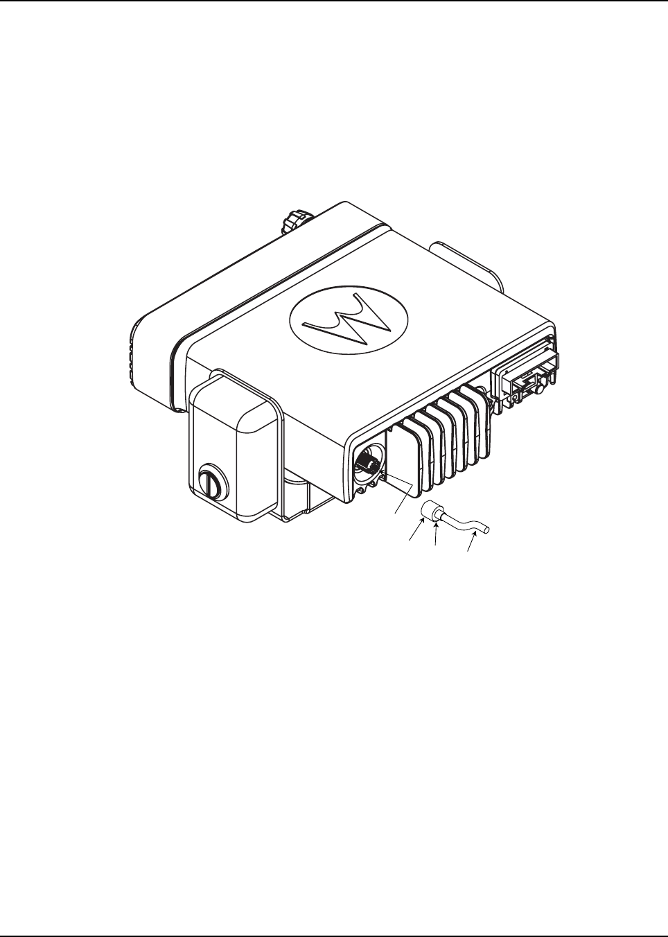
2.5.3 Antenna Connection
To ensure a secure connection of an antenna cable's mini-UHF plug to a radio's mini-UHF jack, their
interlocking features must be properly engaged. If they are not properly engaged, the system will
loosen.
NOTE: Applying excessive force with a tool can cause damage to the antenna or the connector (e.g.,
stripping threads, deforming the collar or connector, or causing the connector to twist in the
housing opening and break).
Motorola recommends the following sequence to ensure proper attachment of the system (see
Figure 2-14):
Figure 2-14 Mini-UHF Connection
1. Make sure that there is sufficient slack in the antenna cable.
2. Make sure that the collar of the antenna cable plug is loose and does not bind.
3. Slide the collar back against the flange. Insert the antenna cable plug’s pin fully into the radio
jack, but do not engage the threads.
4. Ensure that the plug’s and jack’s interlocking features are fully seated. Check this by grasping
the crimp on the cable jack, rotating the cable, and noting any movement. If the features are
seated correctly, there should be NO movement.
5. Finger-tighten the antenna cable plug’s collar onto the radio’s jack.
6. Give a final tug, by hand, to the collar, and retighten by hand as firmly as possible.
7. Use the rubber-coated pliers to grip the plug’s knurled collar, then turn clockwise to tighten
the collar. It should take 1/4 turn or less. Turning counterclockwise loosens the collar.
NOTE: Overtightening the collar can damage the connector and the radio.
Flange
Collar Pulled
Back to Flange
Mini UHF
Jack
Cable

2-14 Installation Details for Standard Configurations
2.6 Microphone Hang-Up Clip
2.6.1 Standard Hang-Up Clip
The hang-up clip must be within reach of the operator(s). Measure this distance before actually
mounting the bracket. Since the bracket has a positive-detent action, the microphone can be
mounted in any position. The microphone hang-up clip must be grounded.
Use the hang-up clip as a template to locate the mounting holes. To avoid interference when
removing the microphone, install the flathead screw in the top clip hole.
2.7 Completing the Installation
Complete the installation by connecting the power wires and plugging in the microphone cable to the
mobile.

Installation Details for Standard Configurations Completing the Installation 2-15
Notes

2-16 Installation Details for Standard Configurations Completing the Installation
Chapter 3 Options and Accessories Installation
3.1 Accessory Installation
The accessories must be installed through the rear accessory connector that is located on the rear of
the radio, adjacent to the power connector. Most of the Motorola-approved accessories are supplied
with female terminals crimped to a 20-gauge wire specifically designed to fit the plug of the rear
accessory connector.
Insert the female terminal into the accessory connector assembly in the appropriate locations. The
accessory connector assembly is provided together with the accessory. Connect the accessory
connector assembly to the rear accessory connector on the back of the mobile. Do not use other
generic terminals in the plug. Generic terminals can cause electrical intermittences and may cause
damage to the plug.
Figure 3-1 Location of the Rear Accessory Connector
Rear Accessory
Connector
3-2 Options and Accessories Installation Accessory Installation
1Pulling this line to ground will activate PTT function, activating the AUX_MIC input.
2Fixed level (independent of volume level) received audio signal, including alert tones. Flat or de-emphasis are
programmed by CPS. Output voltage is approximately 330 mVrms per 1kHz of deviation.
3This input is used to detect when a rear microphone accessory is taken off-hook, to override PL to alert the user to
busy traffic prior to transmitting.
4This microphone signal is independent of the microphone signal on the front microphone connector. The nominal
input level is 80mVrms for 60% deviation. The DC impedance is 660 ohms and the AC impedance is 560 ohms.
5See Figure 2-3 and Figure 2-12 for wiring information.
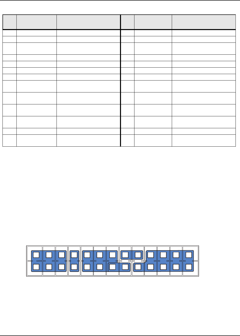
Figure 3-2 Pin Configuration of Rear Accessory Connector (as viewed from the rear of the radio)
Table 3-1 Rear Accessory Connector Pin Functions
Pin
No. Pin Name Pin Function Pin
No. Pin Name Pin Function
1USB+ USB + (Data) 14 Rx Audio Receive Live Audio2
2USB- USB - (Data) 15 AUX Audio 2 PUBLIC Address 2
3VBUS USB Power (5V from USB
accessory/cable) 16 GND Ground
4USB/MAP_ID GND USB/MAP_ID Ground 17 GP5-1 (PTT) 5V Level GPIO, PTT Input1
5MAP_ID_2 Accessory Identifier 18 GND Ground
6MAP_ID_1 Accessory Identifier 19 GP5-2 (Monitor) 5V Level GPIO, Monitor Input3
7SW B+ Switched Battery Voltage 20 GP5-6 5V Level GPIO
8PWRGND Ground 21 GP5-3 5V Level GPIO, Channel
Activity Function
9SPKR- Speaker - (3.2 ohm minimum
impedance) 22 GP5-7 5V Level GPIO
10 SPKR+ Speaker + (3.2 ohm minimum
impedance) 23 EMERGENCY Emergency Switch Input
11 Tx Audio Rear External Microphone
Input424 GP5-8 5V Level GPIO
12 Audio GND Audio Ground 25 IGN SENSE Ignition Sense5
13 AUX Audio 1 PUBLIC Address 1 26 VIP-1 12V Tolerant, 5V GPIO,
External Alarm
1
2
3
4
5
6
7
8
9
10
11
12
13
14
15
16
17
18
19
20
21
22
23
24
25
26
D+
Vbus
SW B+
Spkr-
Tx Audio
Aux Audio Out 1 / RxD
Aux Audio Out 2 / TxD
GP5_1 (PTT)
GP5_2 (Monitor)
GP5_3 (Chan Act)
Emerg Sw
Ign Sense
D-
USB / MAP_ID Ground
MAP_ID_1
Power Ground
Spkr+
Audio Ground
Rx Audio
Ground
Ground
GP5_6
GP5_7
GP5_8
VIP_1 (Ext Alarm)
MAP_ID_2
Options and Accessories Installation Accessory Installation 3-3
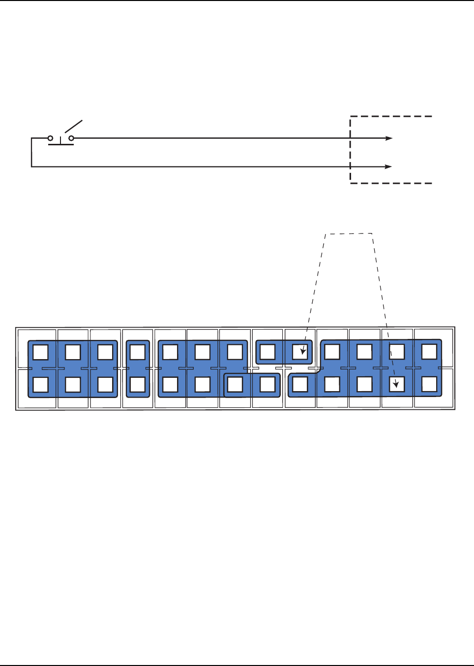
3.1.1 Emergency Pushbutton or Footswitch Installation
Mount the emergency pushbutton (Motorola part number RLN5926A_) or the footswitch (Motorola
part number RLN5929A_) using the hardware that comes with the kit. Press the terminal into the
accessory connector housing. Connect the emergency switch wires to pins 23 and 18 (see
Figure 3-3). Route the finished cable from the switch location to the control head location.
Figure 3-3 Emergency Switch Wiring Diagram
ACCESSORY
CONNECTOR
PIN 23
PIN 18
NOTE 1
SPST NORMALLY OPEN
EMERGENCY SWITCH
1
2
3
4
5
6
7
8
9
10
11
12
13
14
15
16
17
18
19
20
21
22
23
24
25
26
D+
Vbus
MAP_ID_2
SW B+
Spkr-
Tx Audio
Aux Audio Out 1 / RxD
Aux Audio Out 2 / TxD
GP5_1 (PTT)
GP5_2 (Monitor)
GP5_3 (Chan Act)
Emerg Sw
Ign Sense
D-
USB / MAP_ID Ground
MAP_ID_1
Power Ground
Spkr+
Audio Ground
Rx Audio
Ground
Ground
GP5_6
GP5_7
GP5_8
VIP_1 (Ext Alarm)
3-4 Options and Accessories Installation Accessory Installation
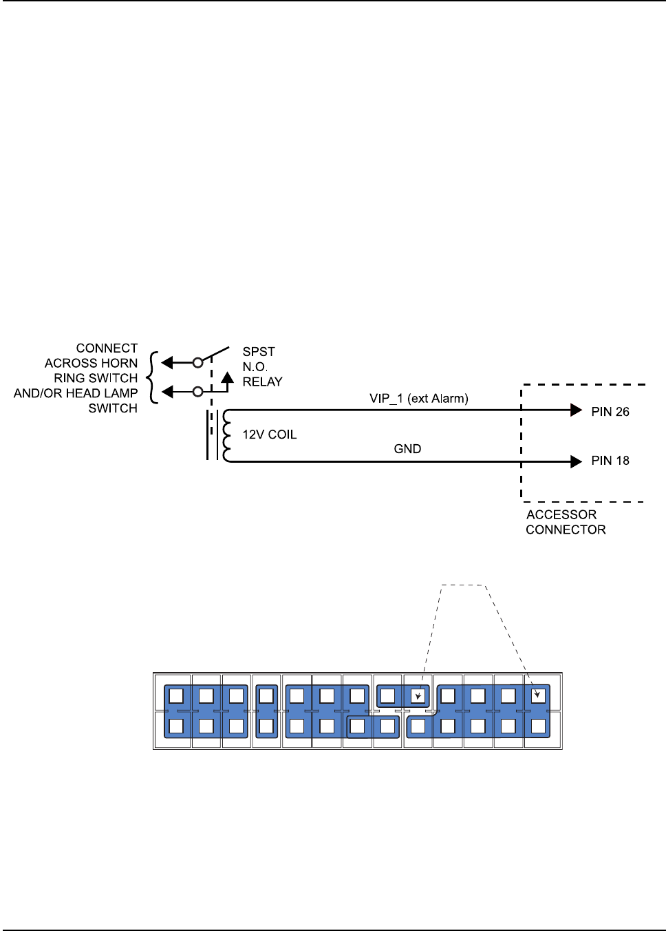
3.1.2 Horn and Lights (External Alarm) Relay
Allows the user to be alerted to an incoming call when away from the vehicle. The vehicle's horn or
lights or both are used depending on which option is connected to the accessory port. When the
radio receives a call alert or emergency alarm/call, there is a delay before activating the horn and/or
lights. The delay is programmable using the Horn & Lights Delay Time feature in the CPS. Once
activated, the Horn and/or Lights remain active depending on the option selected. The Horn & Lights
feature can be toggled between ON or OFF, via a short or long programmable button press (Horn &
Lights On/Off) or Horn/Lights (Utilities Menu) feature.
For installations that use the horn/lights option, select a suitable location for mounting (normally
under the dash) and, referring to Figure 3-4, perform the following procedure:
1. Horn Relay – Connect the relay contacts across the horn ring switch, typically found in the
steering column. Connect the two control wires (female pins) into locations 26 and 18 of the
connector.
2. Lights Relay – Connect the relay across the headlamp ON/OFF switch, typically found in the
steering column. Connect the two control wires (female pins) into locations 26 and 18 of the
accessory connector.
Figure 3-4 Horn and Lights Wiring Diagram
Y
1
2
3
4
5
6
7
8
9
10
11
12
13
14
15
16
17
18
19
20
21
22
23
24
25
26
D+
Vbus
SW B+
Spkr-
Tx Audio
A
ux Audio Out 1 / RxD
Aux Audio Out 2 / TxD
GP5_1 (PTT)
GP5_2 (Monitor)
GP5_3 (Chan Act)
Emerg Sw
Ign Sense
D-
USB / MAP_ID Ground
MAP_ID_1
Power Ground
Spkr+
Audio Ground
Rx Audio
Ground
Ground
GP5_6
GP5_7
GP5_8
VIP_1 (Ext Alarm)
MAP_ID_2
Options and Accessories Installation Accessory Installation 3-5
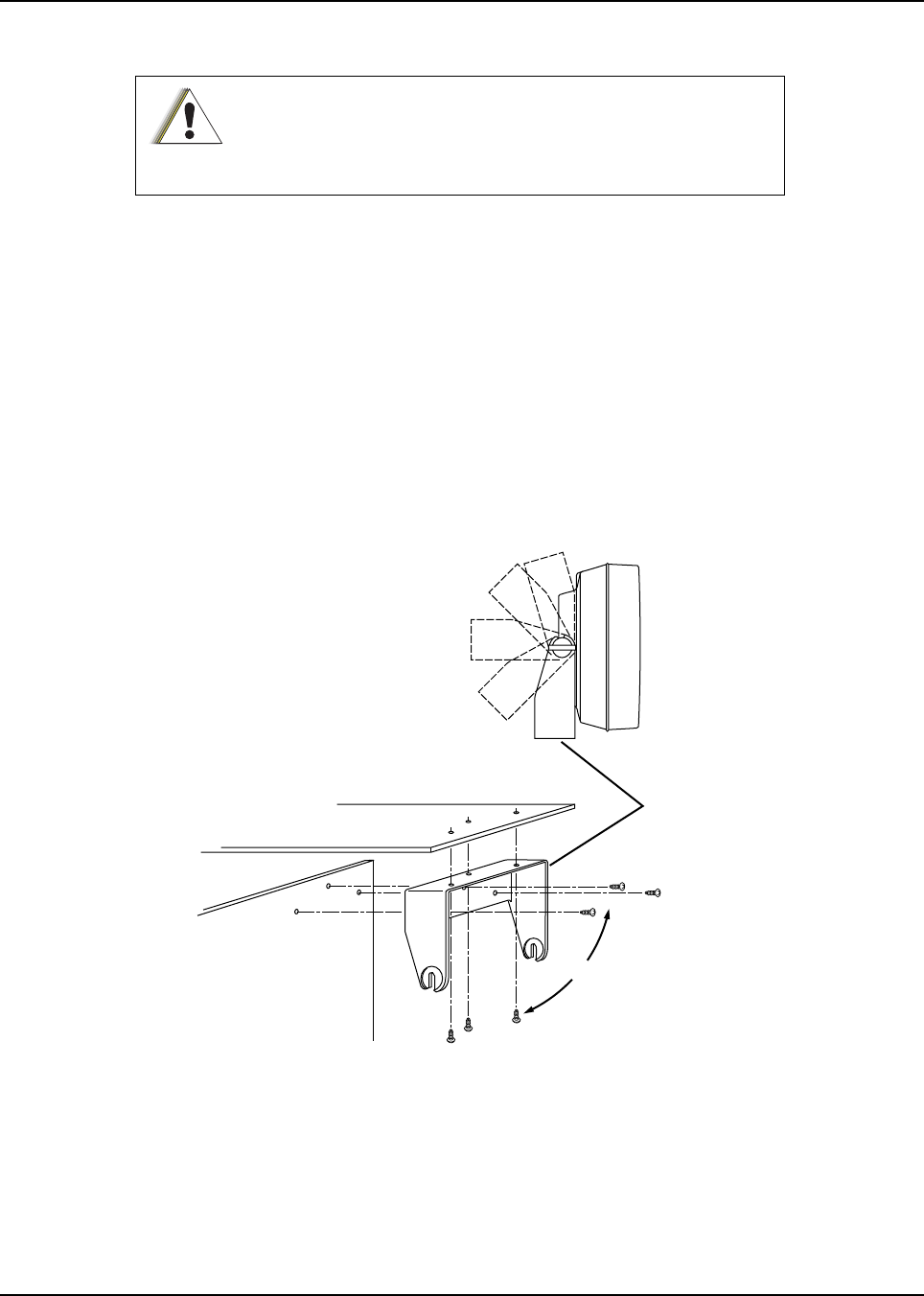
3.1.3 External Speaker
The external speaker kit includes a trunnion bracket that allows the speaker to be mounted in a
variety of ways. With the trunnion bracket, the external speaker can mount permanently on the
dashboard or in accessible firewall areas. The trunnion allows the external speaker to tilt for best
operation. Mount the external speaker out of the way so that it will not be kicked or knocked around
by the vehicle occupants. Mount the external speaker as follows:
1. Use the external speaker mounting bracket as a template to mark the mounting hole
locations.
2. Use the self-drilling screws provided to fasten the trunnion.
3. Attach the external speaker and fasten to the trunnion with two wing screws.
4. Route the speaker wires under the carpet or floor covering, or behind the kick panels. Be sure
the wires are out of the way and will not be snagged and broken by the occupants of the
vehicle.
Figure 3-5 External Speaker Mounting
DO NOT ground the radio's speaker leads. This system has a
floating speaker output (dc voltage on both leads); damage to the
audio circuit will result if either lead is grounded or if they are
shorted together.
C a u t i o n
Dashboard
Firewall
Trunnion
Bracket
OR

3-6 Options and Accessories Installation Accessory Installation
Notes

Chapter 4 Best Practices: Installation & Troubleshooting
In this section are Motorola recommended vehicle installation practices that can address or prevent
many issues, including:
• Radio circuit damage due to over voltage condition
• Radio/Accessories "lock up"
• Radio/Accessories change state/lock-up when radio PTT is depressed
• Radio intermittently resets
• Alternator whine present when transmitting with engine running
• Radio/Accessories turn themselves on/off
4.1 Check Wiring of Ignition and Radio Ignition Sensing
• If it is required to turn the radio on and off via the ignition sense switch, in addition to the control
head’s on/off switch, connect the ignition sense lead to the accessory terminal from the ignition
switch (usually in the vehicle’s fuse panel under accessory or radio).
NOTE: Motorola recommends protecting or isolating the radio’s ignition sense input from voltage spikes
in excess of +/- 40 VDC. Such spikes can be hundreds of volts in amplitude and are common in
larger vehicles (utility trucks, buses and etc.), especially when the source is common to a
solenoid coil. A triggerable oscilloscope is required to determine the existence of such spikes as
most voltmeters cannot measure in short duration (< 1 msec). If the condition of the intended
ignition sense source is unknown, Motorola recommends isolating the source from the radio with
a relay or the use of a suppression diode wired between the source and ground. Any high current
suppression diode (i.e. MR2535) with a breakdown voltage of between 18 and 40 volts will
suffice. A suitable diode kit is available from Motorola parts, kit number HLN6325_.
• If it is required to have the radio power up only via the control head’s on/off switch, then connect
the ignition sense lead directly to the positive terminal of the battery. This will mean the ignition
sense will always be ignored and a re-wiring will be necessary in the future if the operator
chooses any ignition sense CPS setting.

4-2 Best Practices: Installation & Troubleshooting
4.2 Check Physical Installation of Radio Ground and Radio Accessory
Wiring
• Take care to scrape away paint on the chassis at the place where the ground connection is to
be made, and try to keep the ground lead as short as possible.
• Verify that the A+ lead (red) is connected directly to the positive terminal of the battery and
the ground lead (black) is connected to the vehicle’s chassis using as short of a length of
wire as is practical.
• For vehicles that have other types of electronic equipment installed (lights, flashers,
computers siren/PA and etc.), use a separate ground for the mobile radio equipment.
• Make sure that the mobile radio antenna is the minimum required distance (three feet) from
the mobile radio equipment to prevent radio frequency interference (RFI) from interfering
with the radio and/or accessories.
• Do not coil up any excess length of the A+ (red) lead. Doing this may cause a large transient
voltage to be produced when there is a high current drain (e.g. during transmit). This could
cause the radio to reset when the push-to-talk (PTT) is depressed.
• Do not coil up any excessive length of antenna cable, if possible. It may affect the radio’s
receive performance.
4.3 Improve the Electrical Quality of the Power and Ignition Lines
• Use a relay to isolate the vehicle’s ignition switch point (ACC) from the radio’s ignition sense
point. Control this relay from the vehicle’s ignition switch point (ACC). Supply a cleaner
voltage from the positive terminal of the battery into the relay, which will now be attached to
the radio’s ignition sense point. Now the ACC line toggles the relay, instead of directly
toggling the radios ignition sense line.
• Install a Power Line Filter between the A+ lead and the positive terminal of the battery. This is
intended to filter the battery power applied to the transmitter power amplifiers. Pay extra
caution to this because the series filter will introduce a negative spike when the radio
transmits that may cause problems with radio operation.
• For vehicles that use electromechanical relays to control external devices (lights, motors,
switch boxes and etc.), these relay circuits should be isolated as best as possible from the
mobile radio equipment. Also, diode suppression should be used across the relay contacts to
minimize the noise produced by the collapsing magnetic field.
• If the ignition sense switch is to be used, make sure that there is not a large voltage drop
between the A+ point (usually the positive terminal of the battery) and the ignition sense
point. In general, the voltage difference between these two points, should not be greater than
1.5 volts when all accessories/air-conditioner, etc. are turned on. Refer to the Basic Service
Manual for specifications for minimum and maximum voltage levels. Typical battery voltage
levels are 13.6V +/- 20%.

Best Practices: Installation & Troubleshooting 4-3
4.4 Jump-Start the Vehicle
The state of your radio prior to needing a jump-start may be unknown, and the radio may attempt to
return to its last state (radio ON), when doing a jump-start. Therefore, Motorola recommends the
following steps be taken before jump-starting any vehicle containing a radio.
1. Locate the ignition sense line and the main power leads (thick red wire) near the battery
positive terminal.
NOTE: These lines are fused. In the event these lines are not fused (add the appropriate fuse in line)
use whatever tools necessary to physically disconnect the ignition sense and power lines
from the battery terminal.
2. Open up the fuse holders and remove the fuses out of the kits.
3. Re-tighten the fuse holders but without the fuses to insure that ignition sense and power lines
do not interfere with any moving parts.
4. Proceed with the jump-start routine as described by your vehicle owner’s manual.
5. Once the jump-start process is complete, re-install the fuses into their holders.
4.5 Eliminate Noise/Howling from PA Speaker
1. Refer to Section 2.1.2 for recommended methods of installation available for the mobile
two-way radio, with accessories placed to the vehicle as desired.
2. Refer to Figure 2-3 and Figure 2-4 for the wiring diagrams for the recommended
configurations.
Do not jump-start vehicle with radio power or ignition sense cables connected.
Damage to the radio and/or accessories may result.
C a u t i o n

Notes
4-4 Best Practices: Installation & Troubleshooting

Appendix A Replacement Parts Ordering
A.1 Basic Ordering Information
When ordering replacement parts or equipment information, the complete identification number
should be included. This applies to all components, kits, and chassis. If the component part number
is not known, the order should include the number of the chassis or kit of which it is a part, and
sufficient description of the desired component to identify it.
See Related Publications on page 1-v for the radio basic service manuals which consists the parts
list and part numbers for ordering.
A.2 Motorola Online
Motorola Online users can access our online catalog at:
https://businessonline.motorolasolutions.com
To register for online access, please call 1-800-422-4210 (for U.S. and Canada Service Centers
only). International customers can obtain assistance by go to http://www.motorolasolutions.com ,
select your region > SUPPORT.
A.3 Mail Orders
Mail orders are only accepted by the U.S. Federal Government Markets Division (USFGMD):
Motorola Inc.
7031 Columbia Gateway Drive
3rd Floor - Order Processing
Columbia, MD 21046
U.S.A.
A.4 Telephone Orders
Radio Products and Solutions Organization*
(United States and Canada)
7:00 AM to 7:00 PM (Central Standard Time)
Monday through Friday (Chicago, U.S.A.)
1-800-422-4210
1-847-538-8023 (United States and Canada)
U.S. Federal Government Markets Division (USFGMD)
1-877-873-4668
8:30 AM to 5:00 PM (Eastern Standard Time)

A-2 Replacement Parts Ordering Fax Orders
A.5 Fax Orders
Radio Products and Solutions Organization*
(United States and Canada)
1-800-622-6210
1-847-576-3023 (International)
USFGMD
(Federal Government Orders)
1-800-526-8641 (For Parts and Equipment Purchase Orders)
A.6 Parts Identification
Radio Products and Solutions Organization*
(United States and Canada)
1-800-422-4210
A.7 Product Customer Service
Radio Products and Solutions Organization (United States and Canada)
1-800-927-2744
* The Radio Products and Solutions Organization (RPSO) was formerly known as the Radio
Products Services Division (RPSD) and/or the Accessories and Aftermarket Division (AAD).

Appendix B Motorola Service Centers
B.1 Servicing Information
If a unit requires further complete testing, knowledge and/or details of component level
troubleshooting or service than is customarily performed at the basic level, please send the radio to
a Motorola Service Center as listed below.
B.2 Motorola Service Center
1220 Don Haskins Drive
Suite A
El Paso, TX 79936
Tel: 915-872-8200
B.3 Motorola Federal Technical Center
10105 Senate Drive
Lanham, MD 20706
Tel: 1-800-969-6680
Fax: 1-800-784-4133
B.4 Motorola Canadian Technical Logistics Center
Motorola Canada Ltd.
8133 Warden Avenue
Markham, Ontario, L6G 1B3
Tel: 1-800-543-3222
Fax: 1-888-331-9872 or 1-905-948-5970

B-2 Motorola Service Centers Motorola Canadian Technical Logistics Center
Notes

Index Index
A
accessories
installing
dash mount ........................................................3-1
antenna
cable, see Cables, antenna
connection ...........................................................2-13
diagrams ..............................................................2-13
installing ............................................................... 2-11
mounting .............................................................. 2-11
B
base stations .............................................................1-6
black lead ..................................................................2-8
C
cables
antenna .........................................................2-4, 2-13
connection .............................................................4-1
diagrams ...............................2-2, 2-3, 2-9, 2-10, 2-13
ignition ................................................................. 2-11
ignition sense ....................................................... 2-11
power .....................................................................2-8
configurations
dash mount ............................................................1-5
control head
dash mount ............................................................1-5
see also specific model names
control stations ..........................................................1-6
D
dash mount
accessories installations ........................................3-1
configuration ..........................................................1-5
installation .......................................................2-2, 2-3
radio dimensions ....................................................1-2
trunnion ..................................................................2-5
E
emergency footswitch ................................................3-3
emergency pushbutton ..............................................3-3
F
footswitch, emergency ...............................................3-3
H
horn relay ..................................................................3-4
I
ignition
cable .................................................................... 2-11
installation
examples ...............................................................2-1
J
J2
pin configuration .............................................2-2, 2-3
L
leads
black ......................................................................2-8
light relay ...................................................................3-4
locking kit, installing ...................................................2-6
M
microphone
hang-up clip, standard .........................................2-14
S-hook ...................................................................2-5
mounting configurations ............................................2-4
dash ................................................................1-5, 2-5
O
ordering replacement parts ...................................... A-1
P
parts, ordering replacement ..................................... A-1
pin
functions ................................................................3-2
removal tool ....................................................1-1, 2-1
pin configurations
J2 ....................................................................2-2, 2-3
pushbutton, emergency .............................................3-3
R
rear accessory jack, see J2
relays
horn ........................................................................3-4
light ........................................................................3-4
replacement parts, ordering ..................................... A-1
S
speaker
connecting ...........................................................2-14
mounting ................................................................3-5
T
tools, required ............................................................2-1
trunnion

Index-2
bracket for speaker ................................................ 3-5
dash mount ............................................................ 2-5
locking kit ............................................................... 2-6
mounting bracket ................................................... 2-5
orientation .............................................................. 2-4
transmission hump mounting ................................ 2-5
W
wiring diagrams ......................................................... 2-2