Motorola Solutions 92FT7114 MC-EDGE UHF Range 2, Edge Sensor Gateway User Manual Manual
Motorola Solutions, Inc. MC-EDGE UHF Range 2, Edge Sensor Gateway Manual
UserManual.wiki
>
Motorola Solutions
>
92FT7114 User Manual
>
Manual
Contents
1.
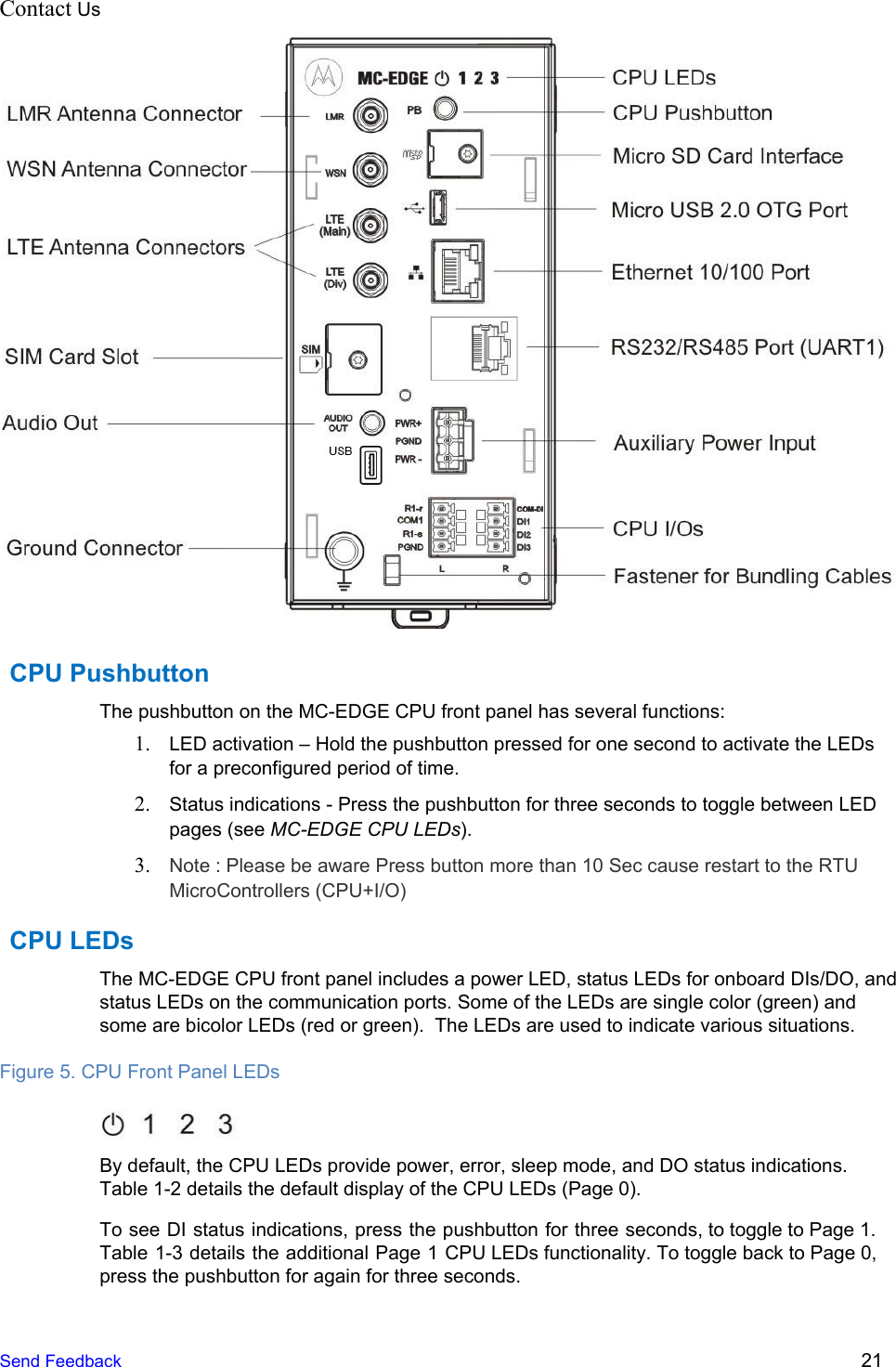
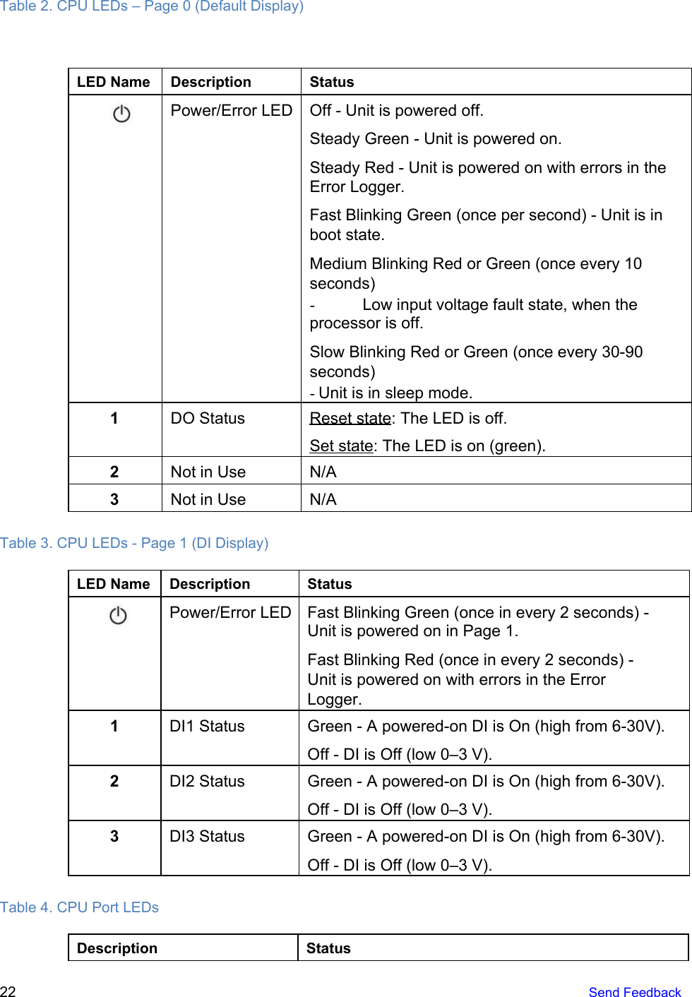
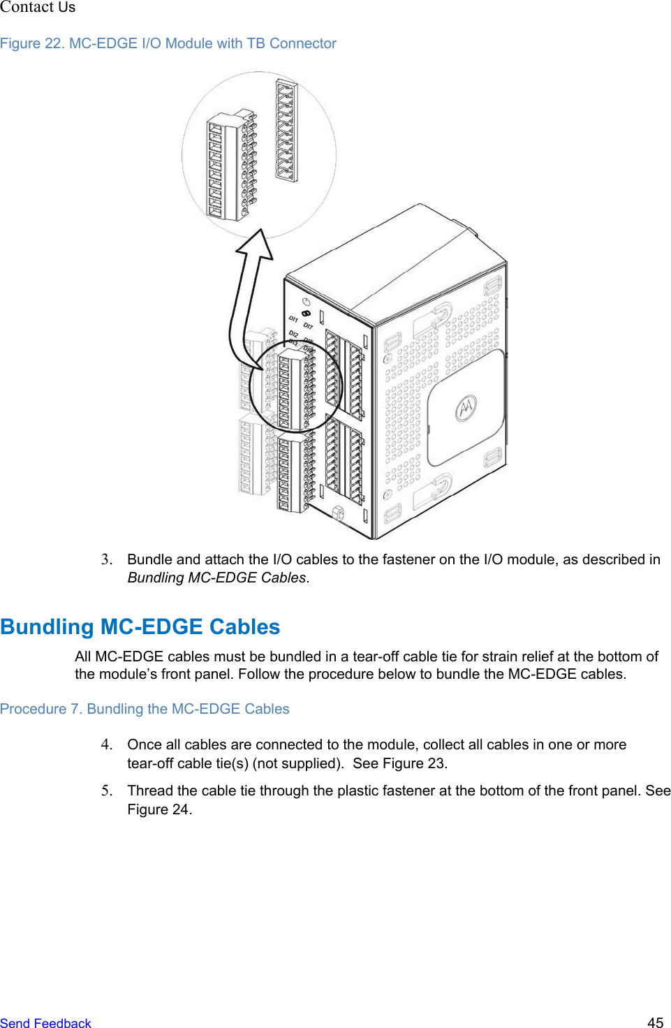
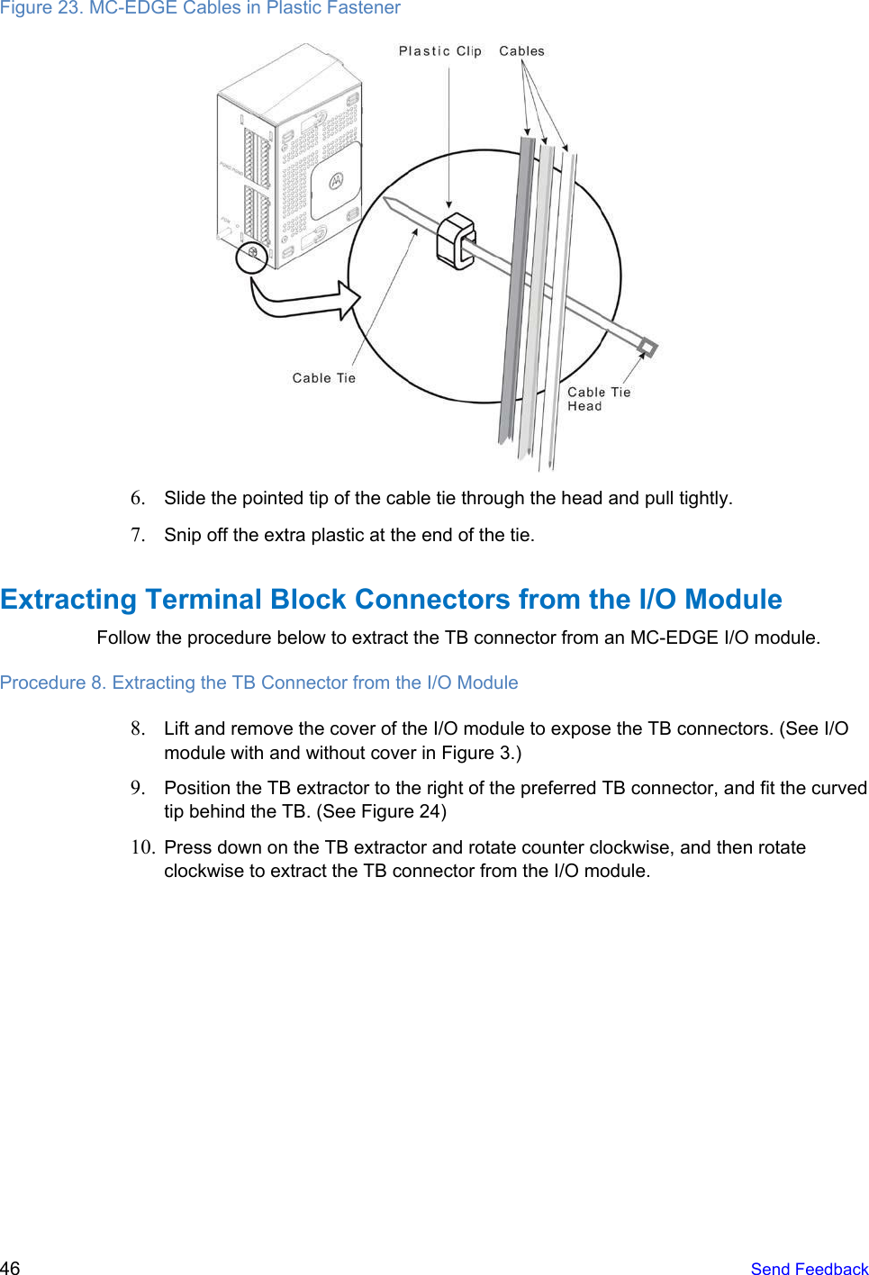
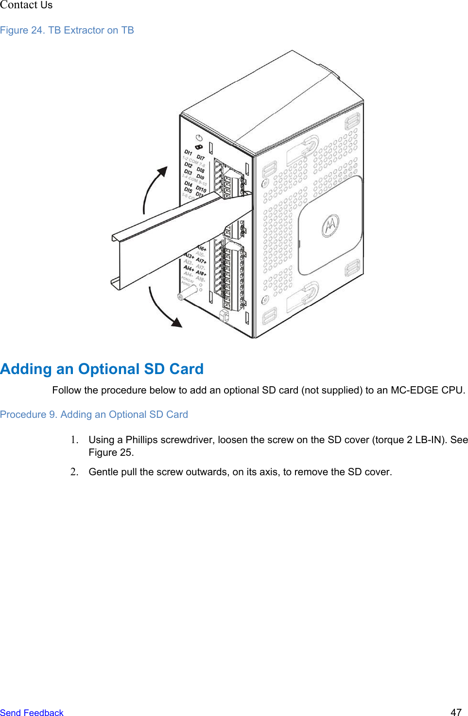
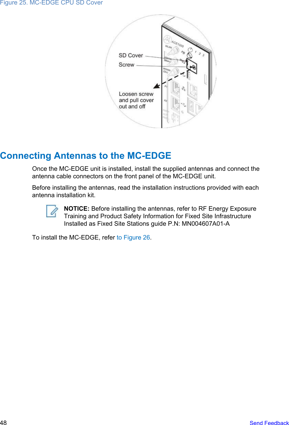
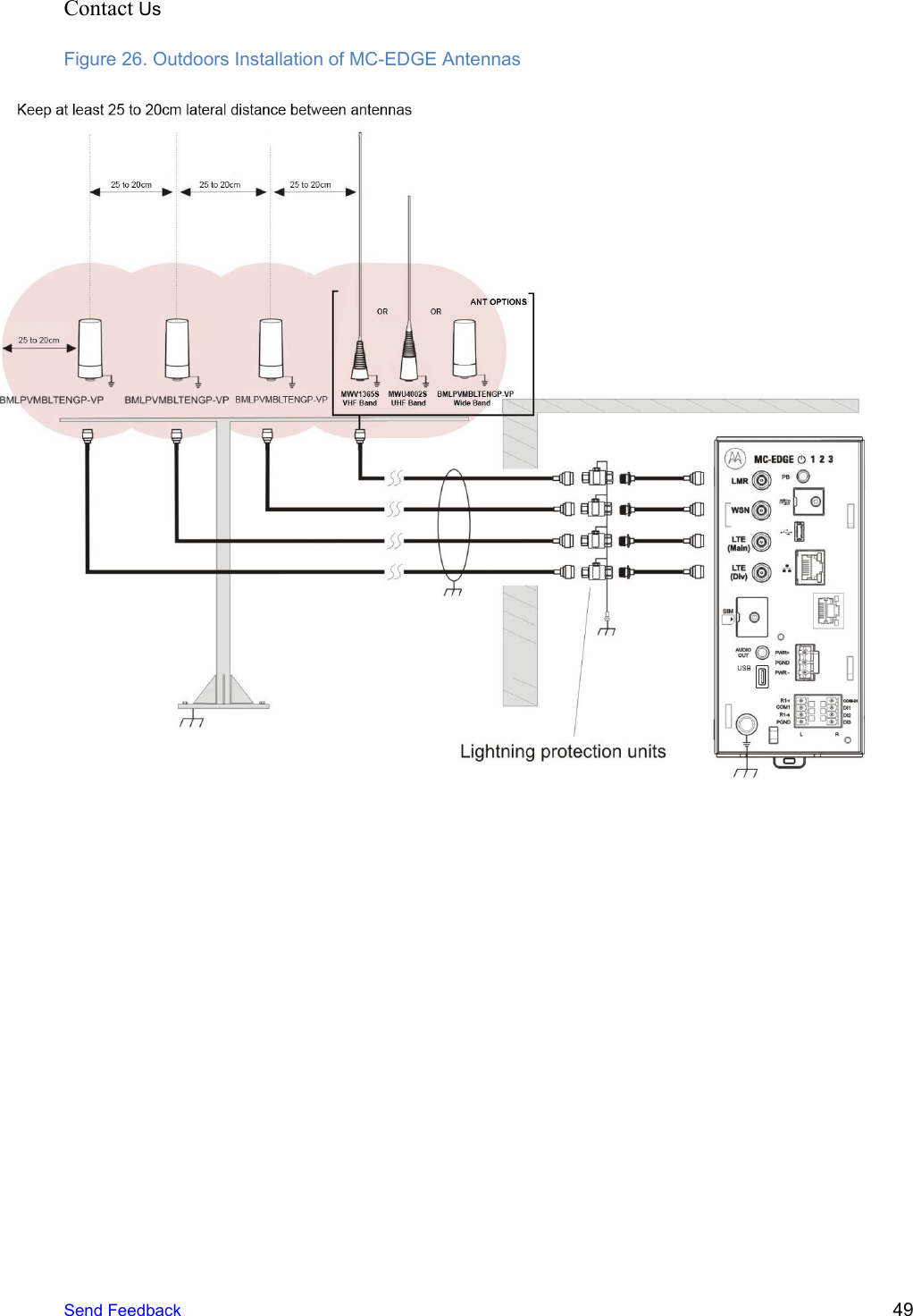
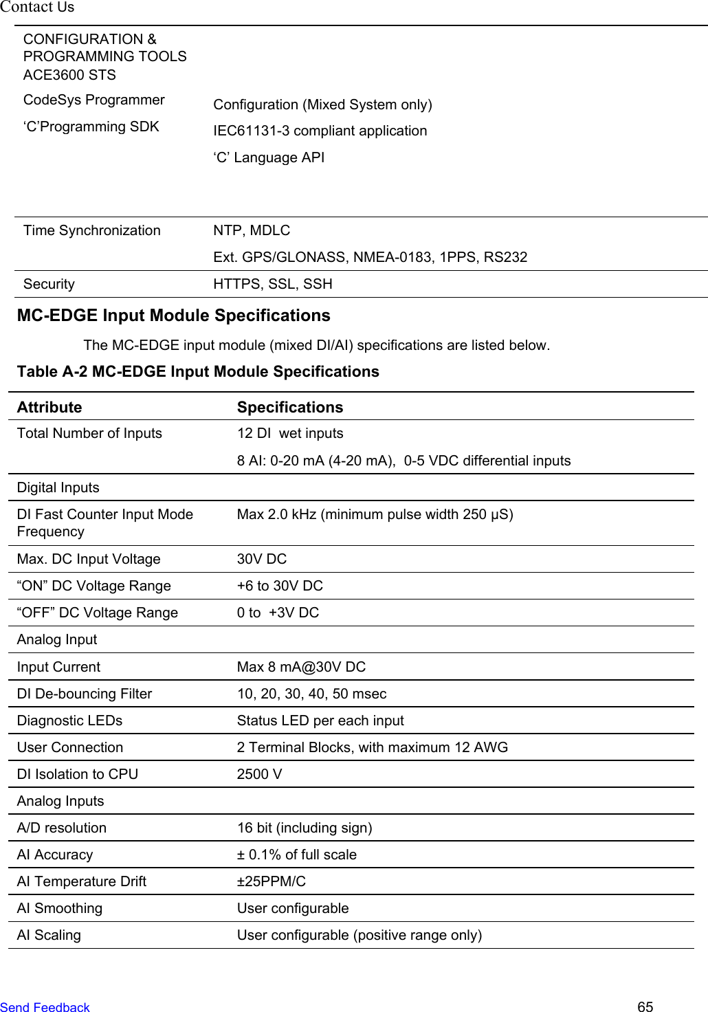
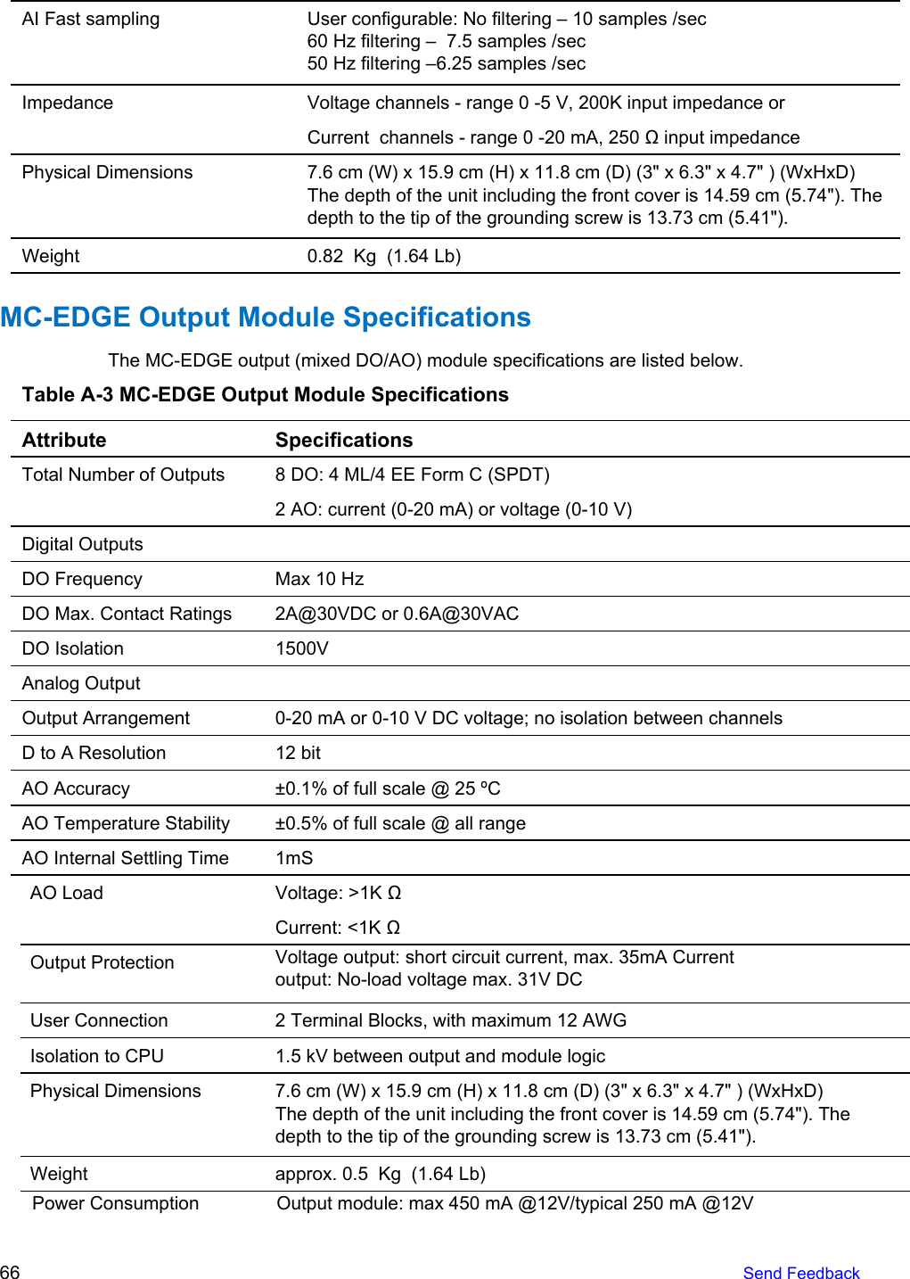
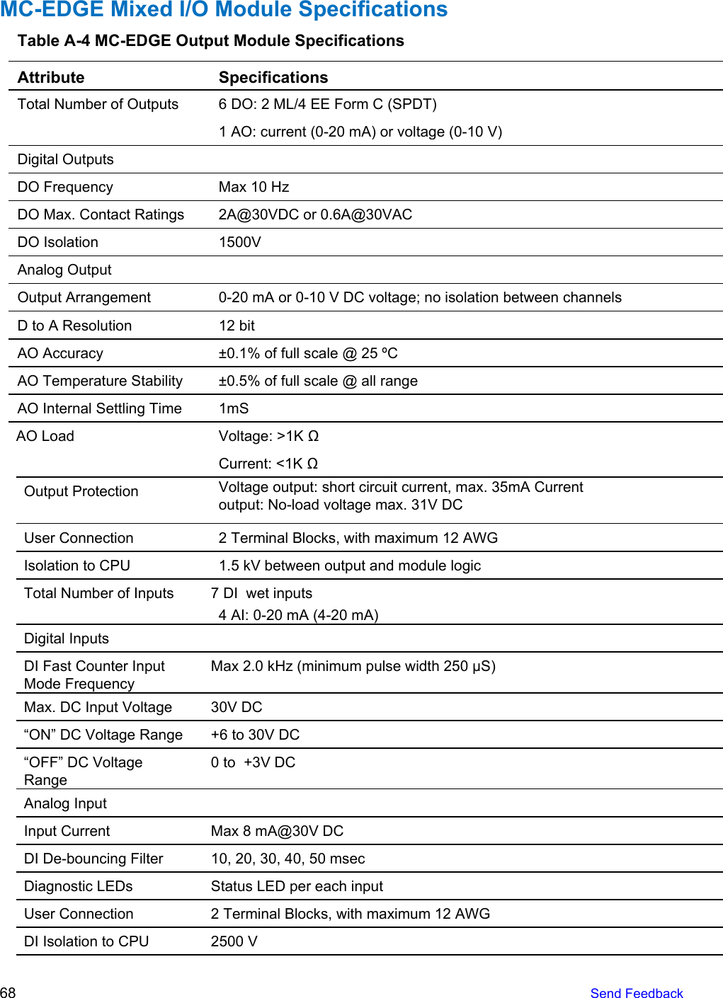
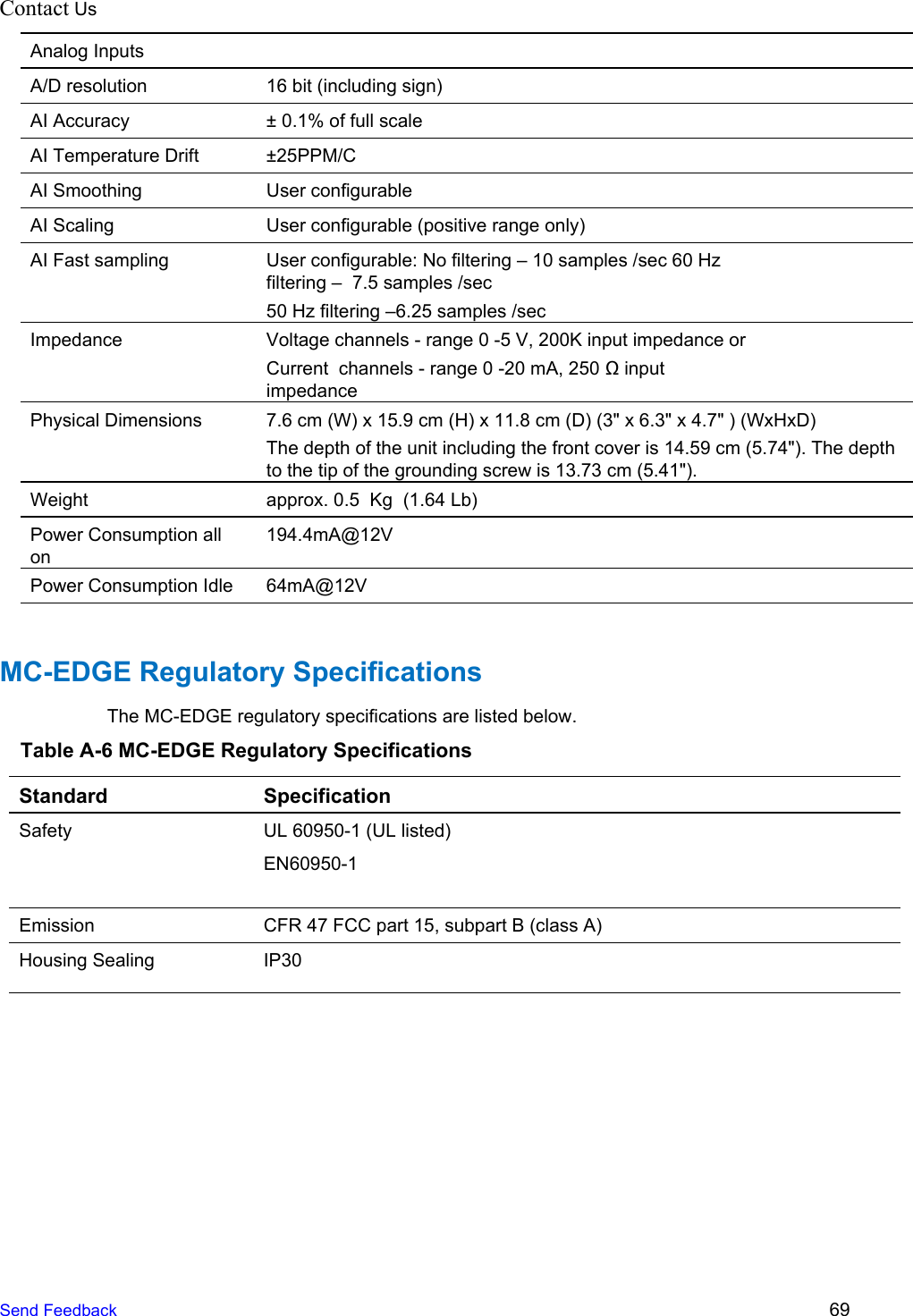
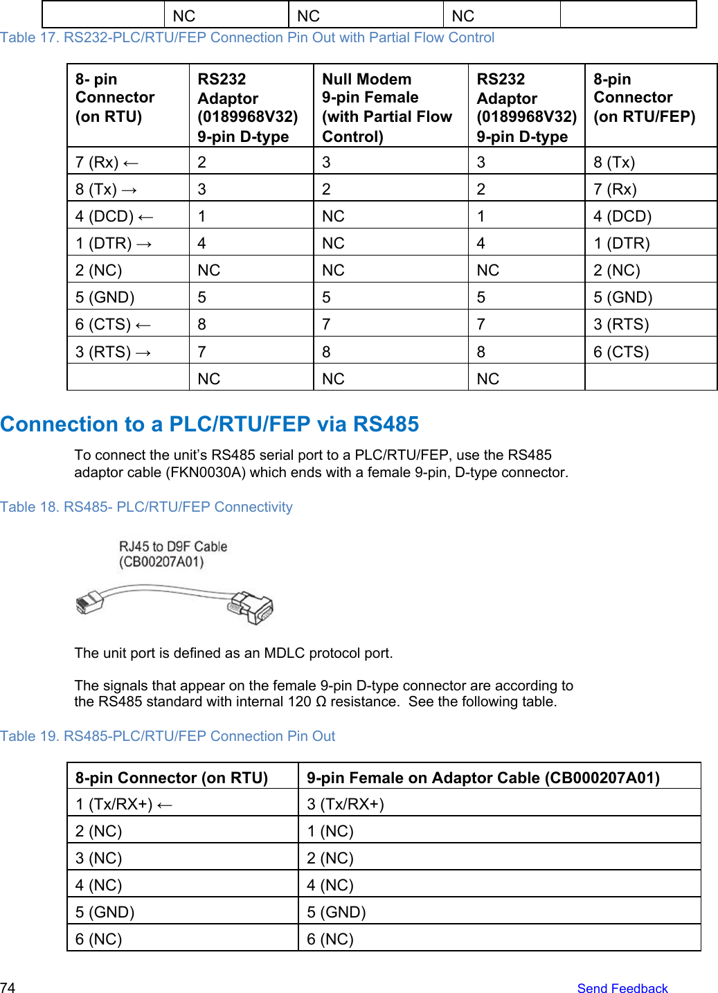
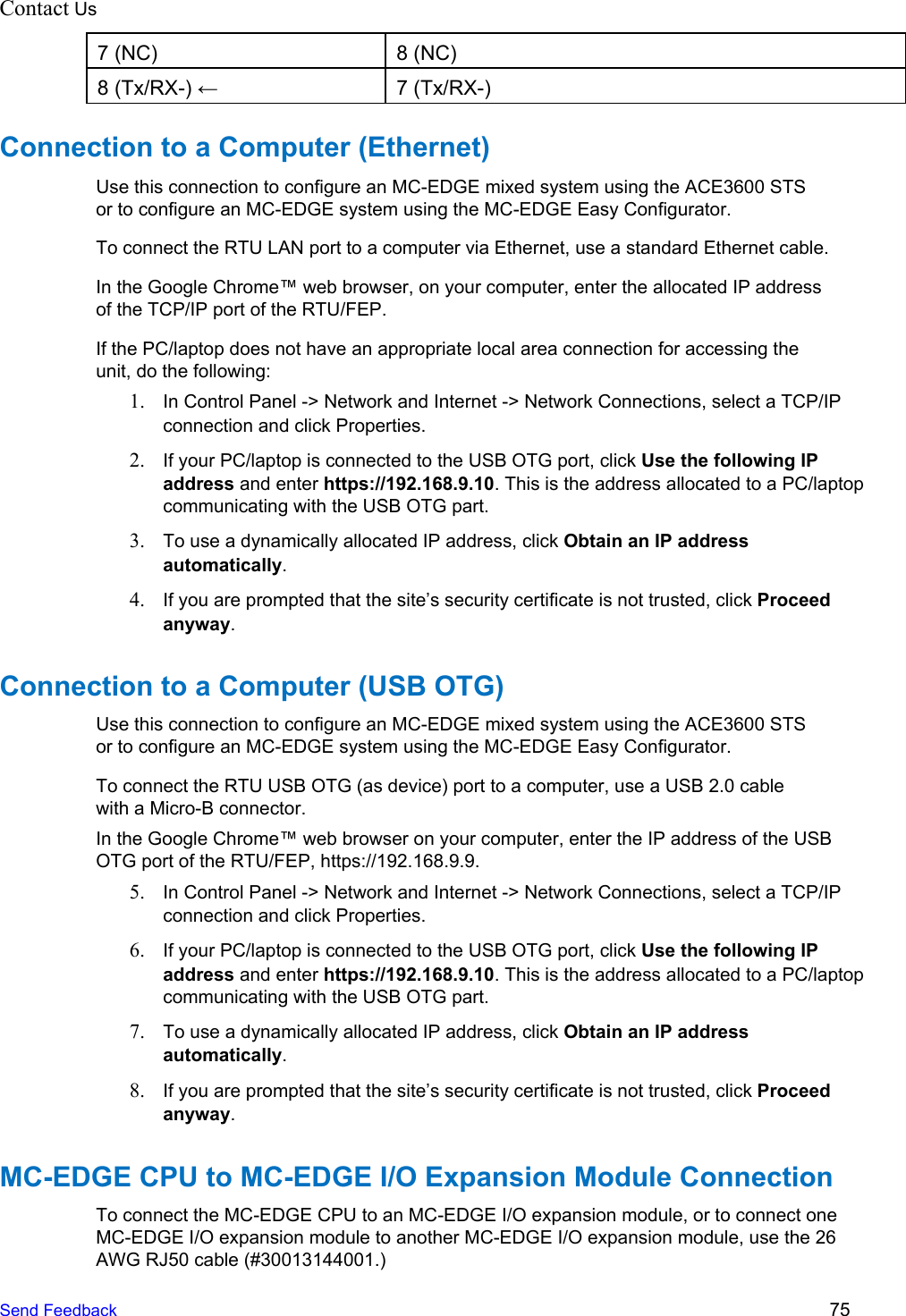
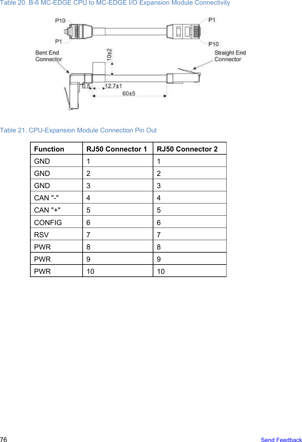
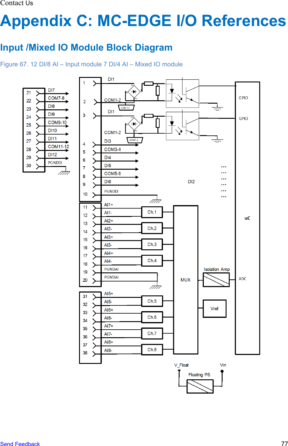
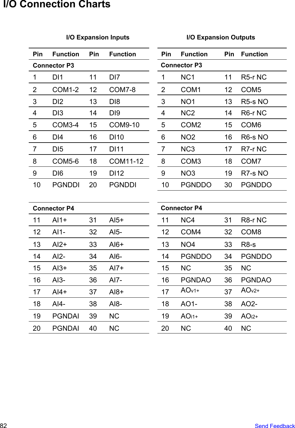
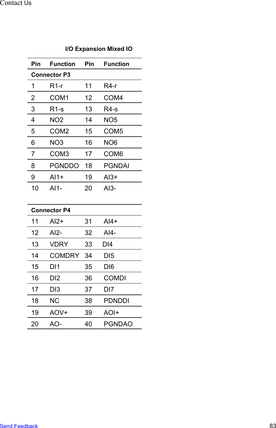
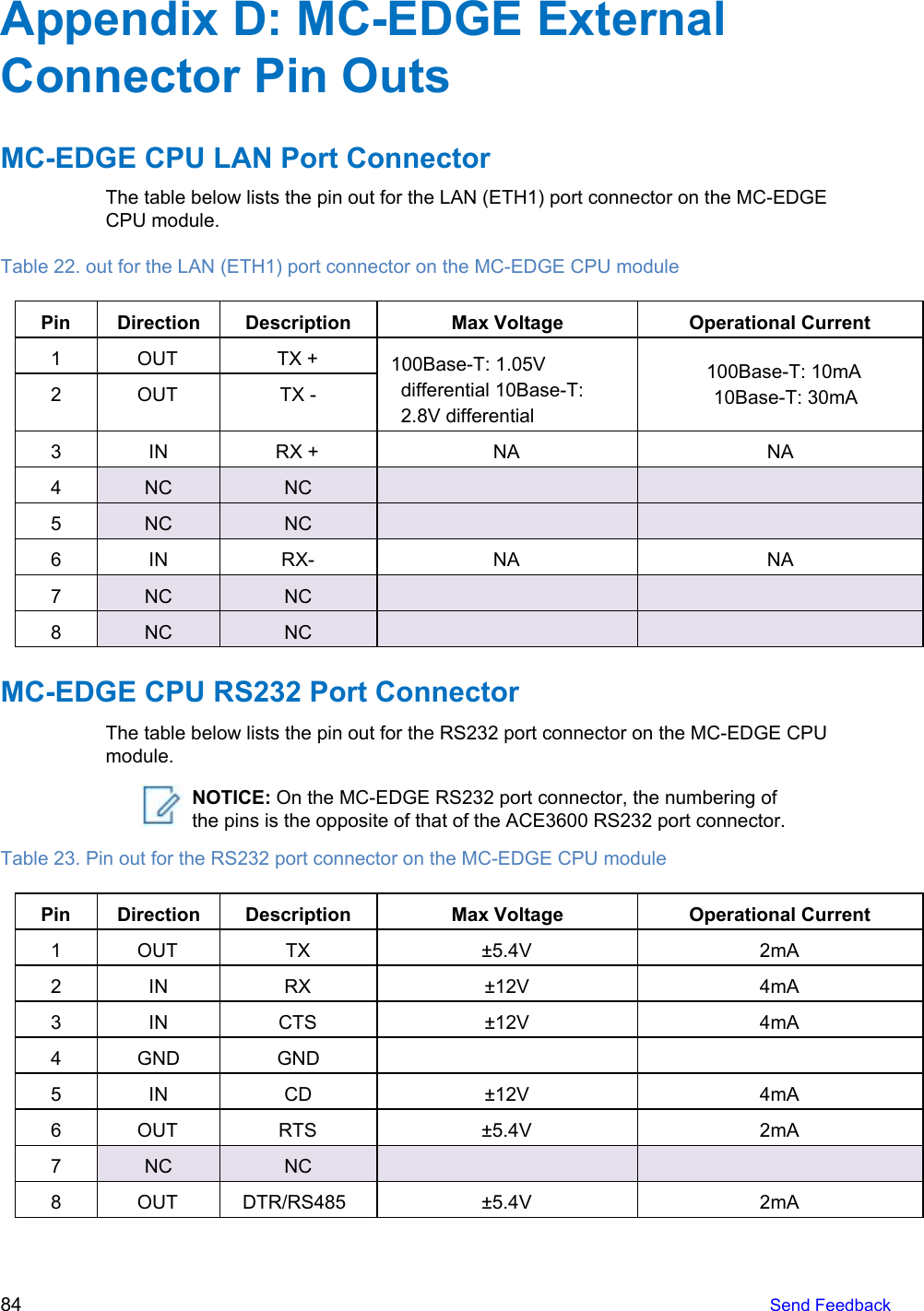
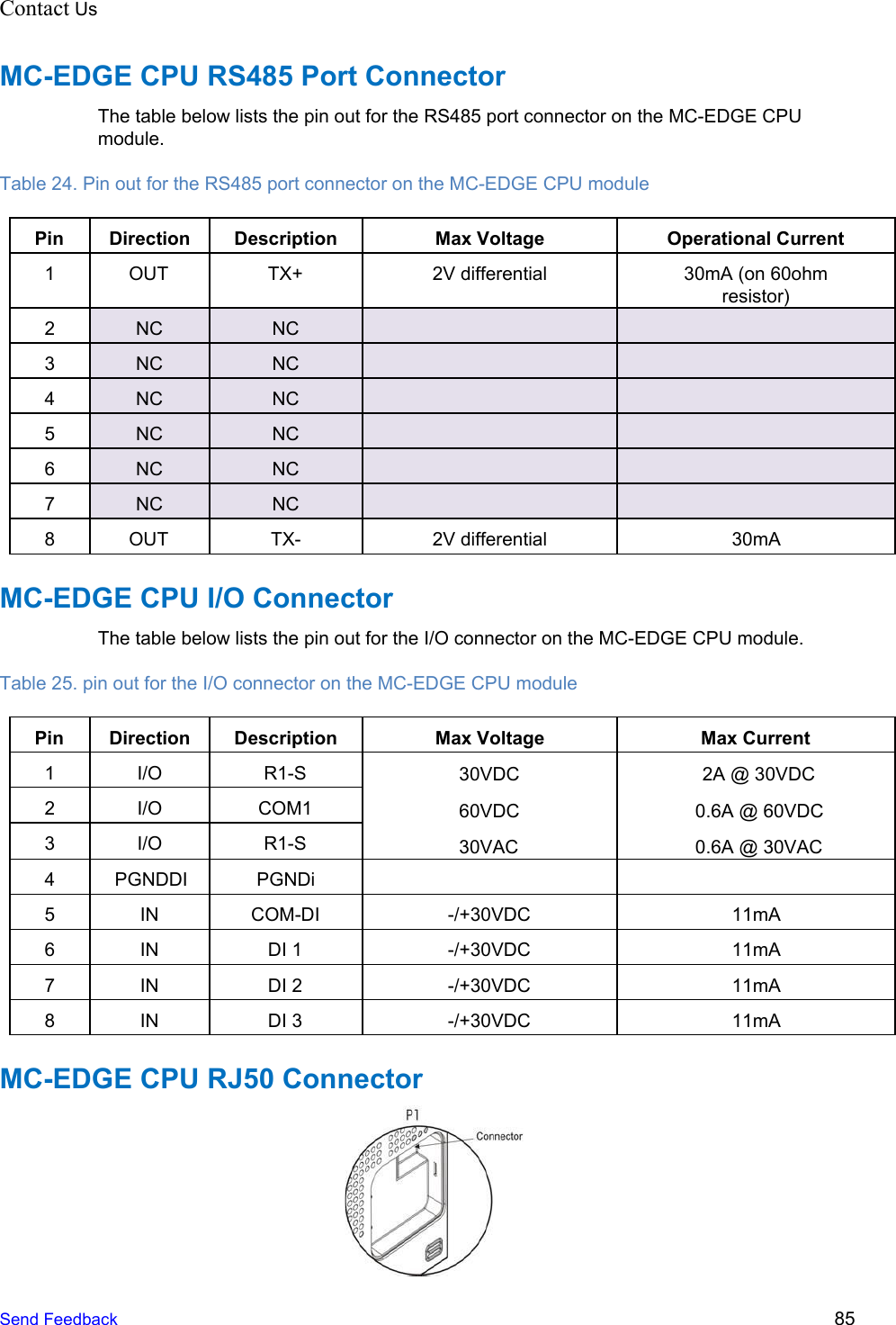
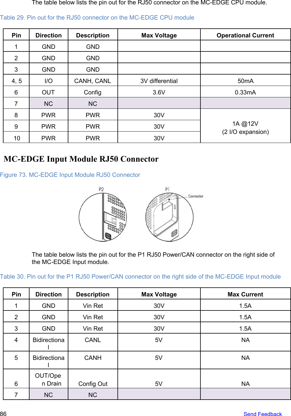
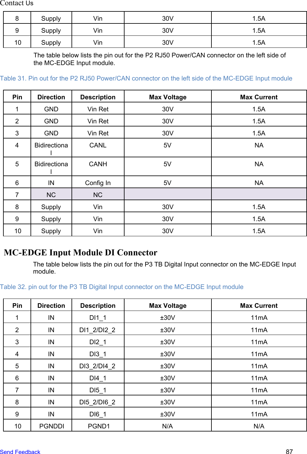
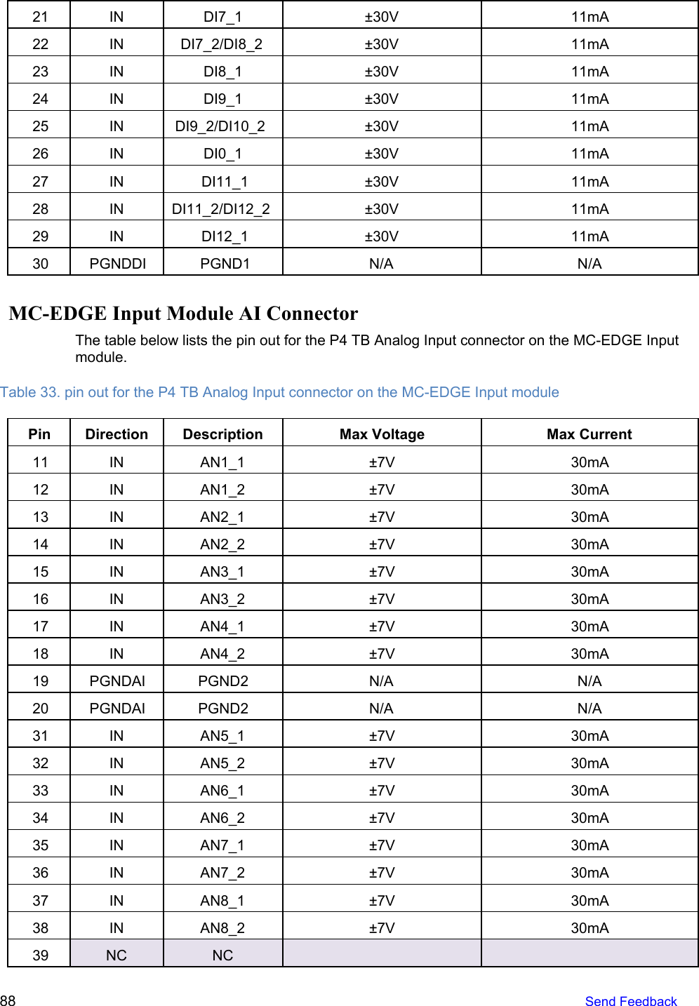
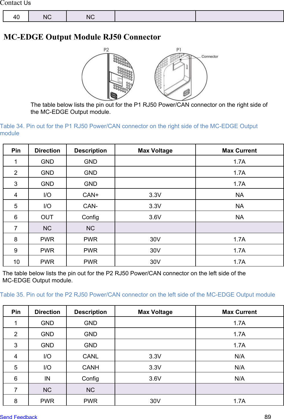
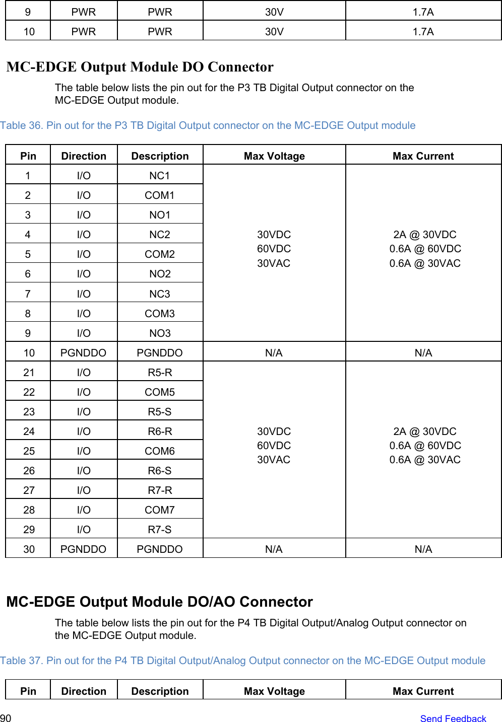
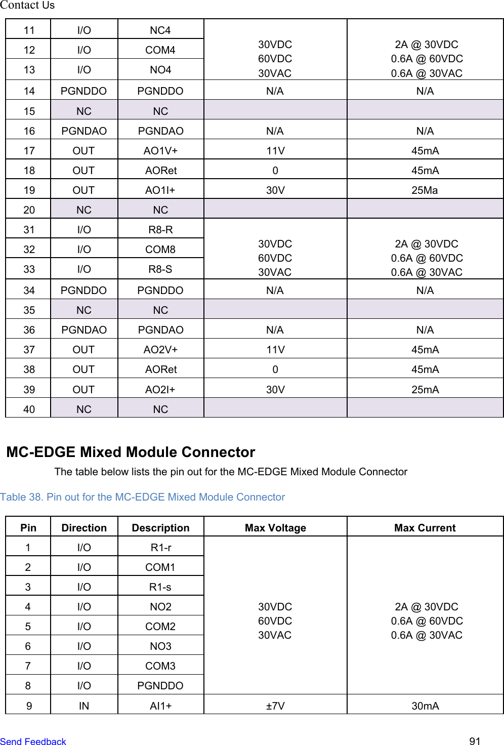
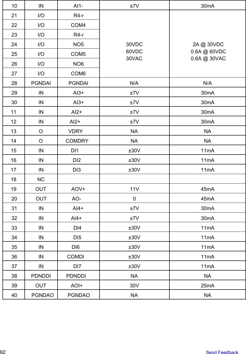
Manual
2.
RF Safety Manual
Manual
Navigation menu
Upload a User Manual
Namespaces
Wiki Guide
HTML
PDF
Info
Views
User Manual
Discussion / Help
Navigation