Motorola Solutions 92FT7118 Mobile 2-Way Radio with WiFi User Manual APX TWO WAY RADIOS
Motorola Solutions, Inc. Mobile 2-Way Radio with WiFi APX TWO WAY RADIOS
UserManual.wiki
>
Motorola Solutions
>
92FT7118 User Manual
>
Users Guide
Contents
1.
Users Guide
2.
Quick Reference Guide
3.
Installation Manual 1 of 2
4.
Installation Manual 2 of 2
5.
RF Safety Manual
6.
Manual
Users Guide
Navigation menu
Upload a User Manual
Namespaces
Wiki Guide
HTML
PDF
Info
Views
User Manual
Discussion / Help
Navigation

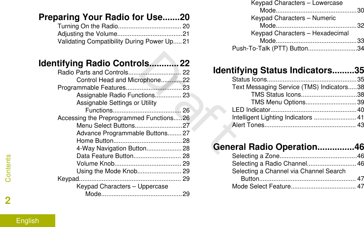
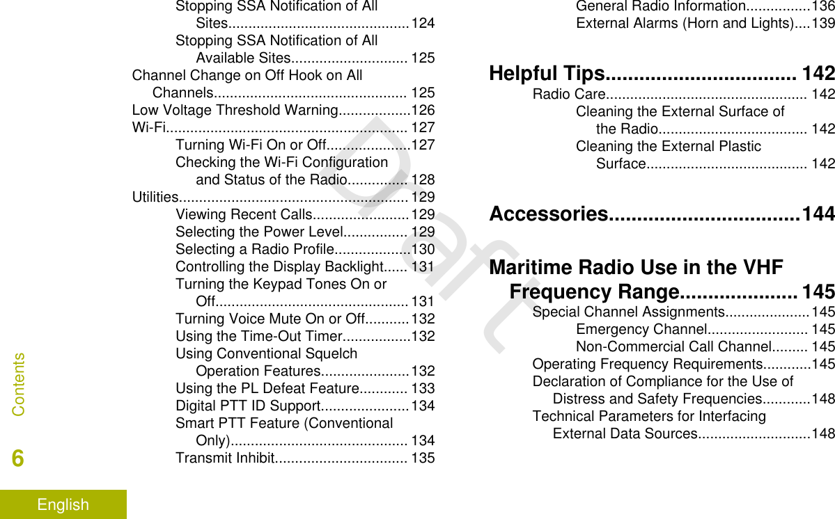
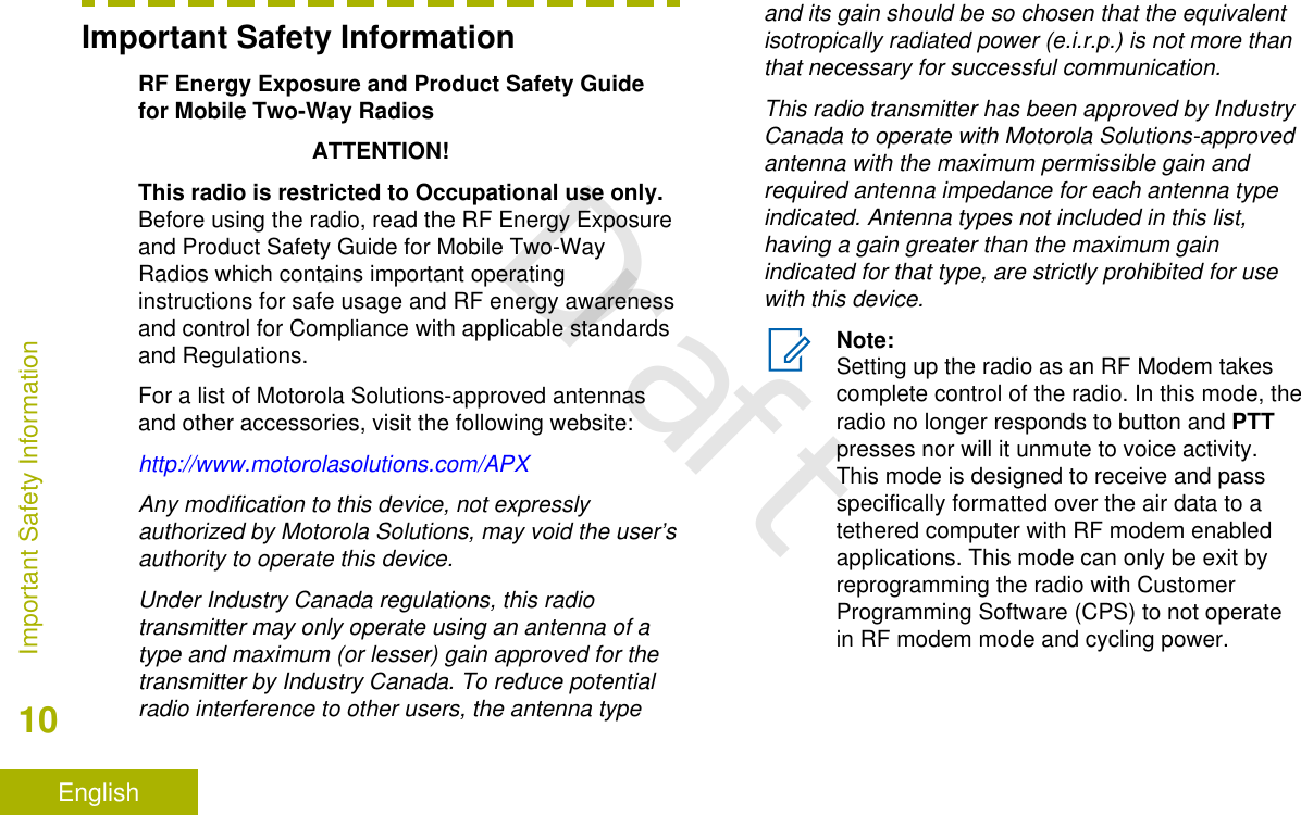
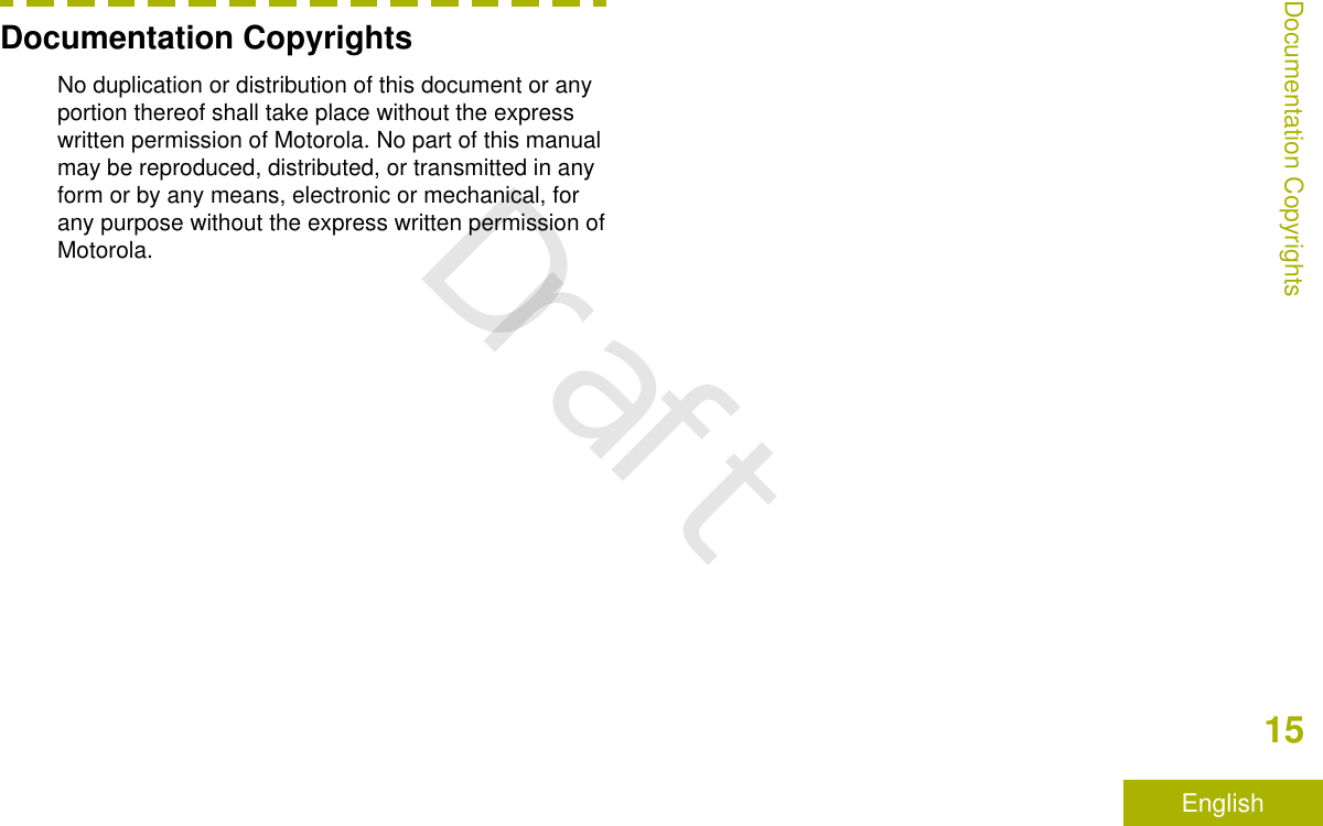
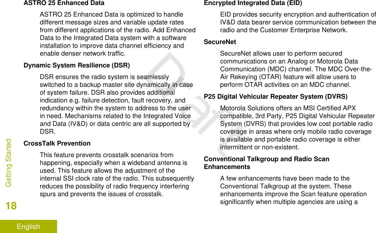
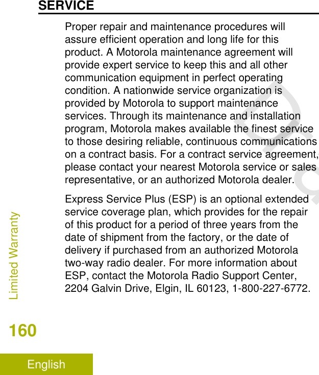
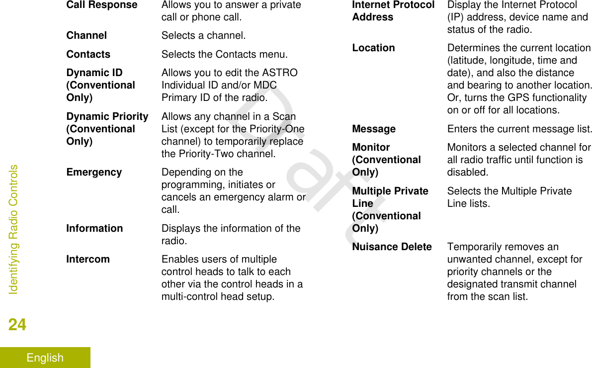
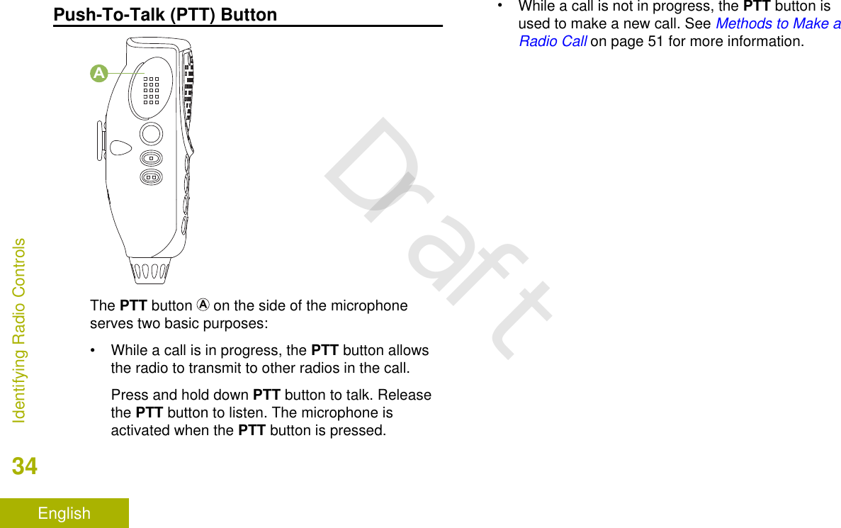
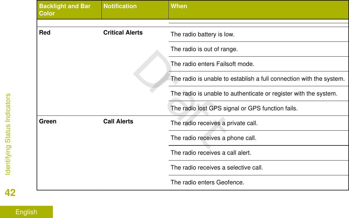
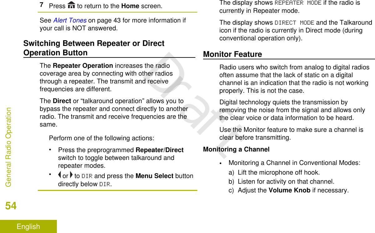
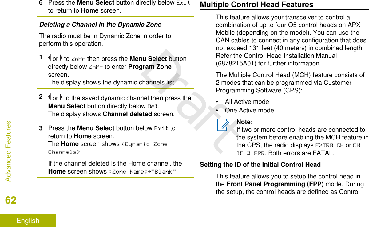
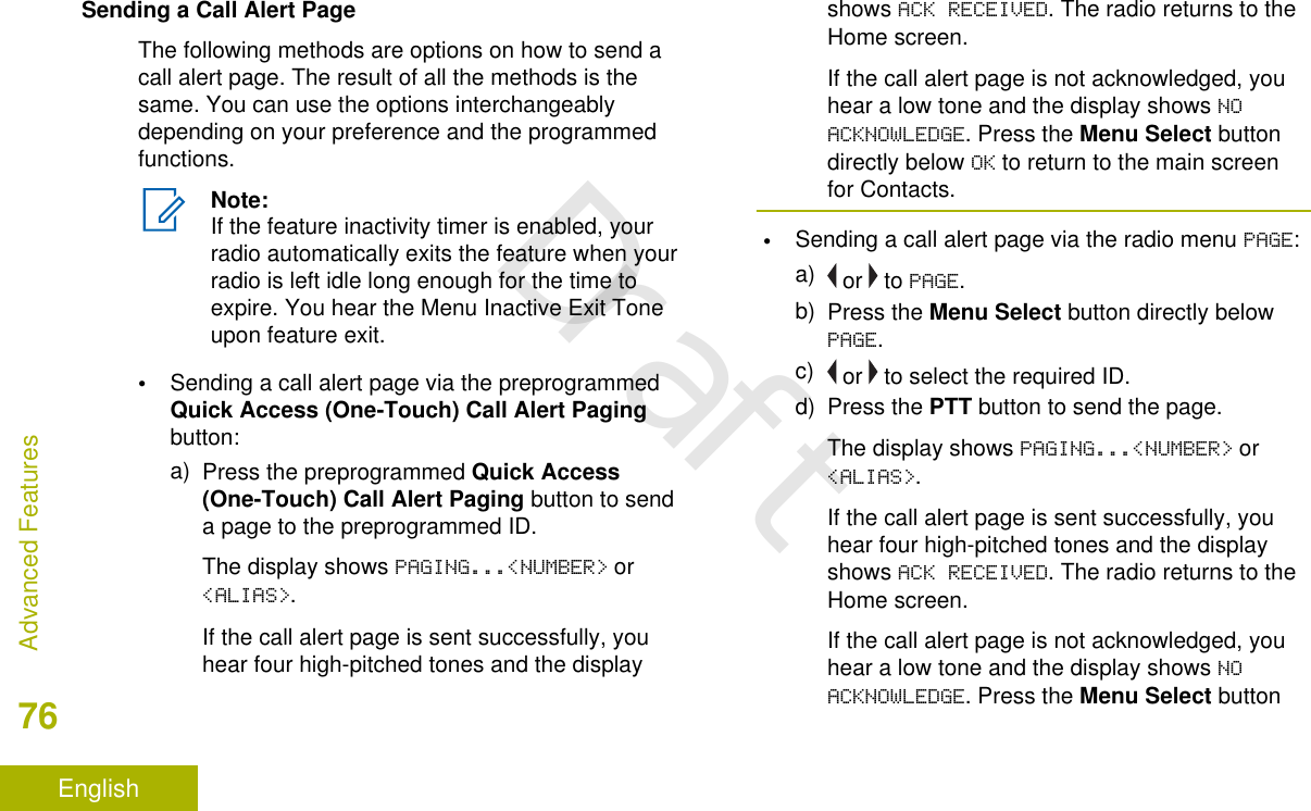
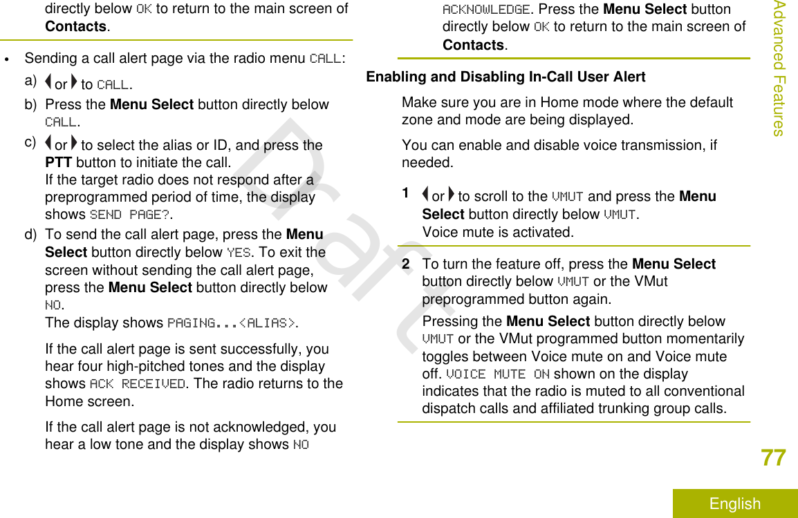
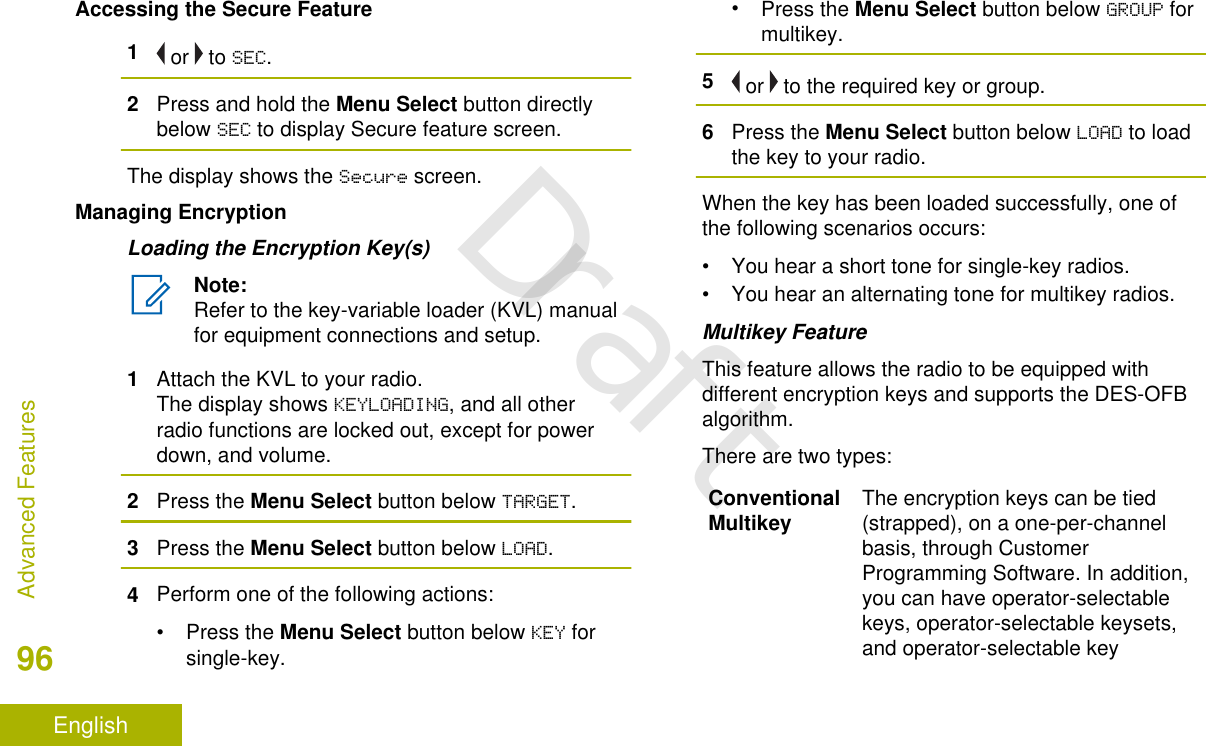
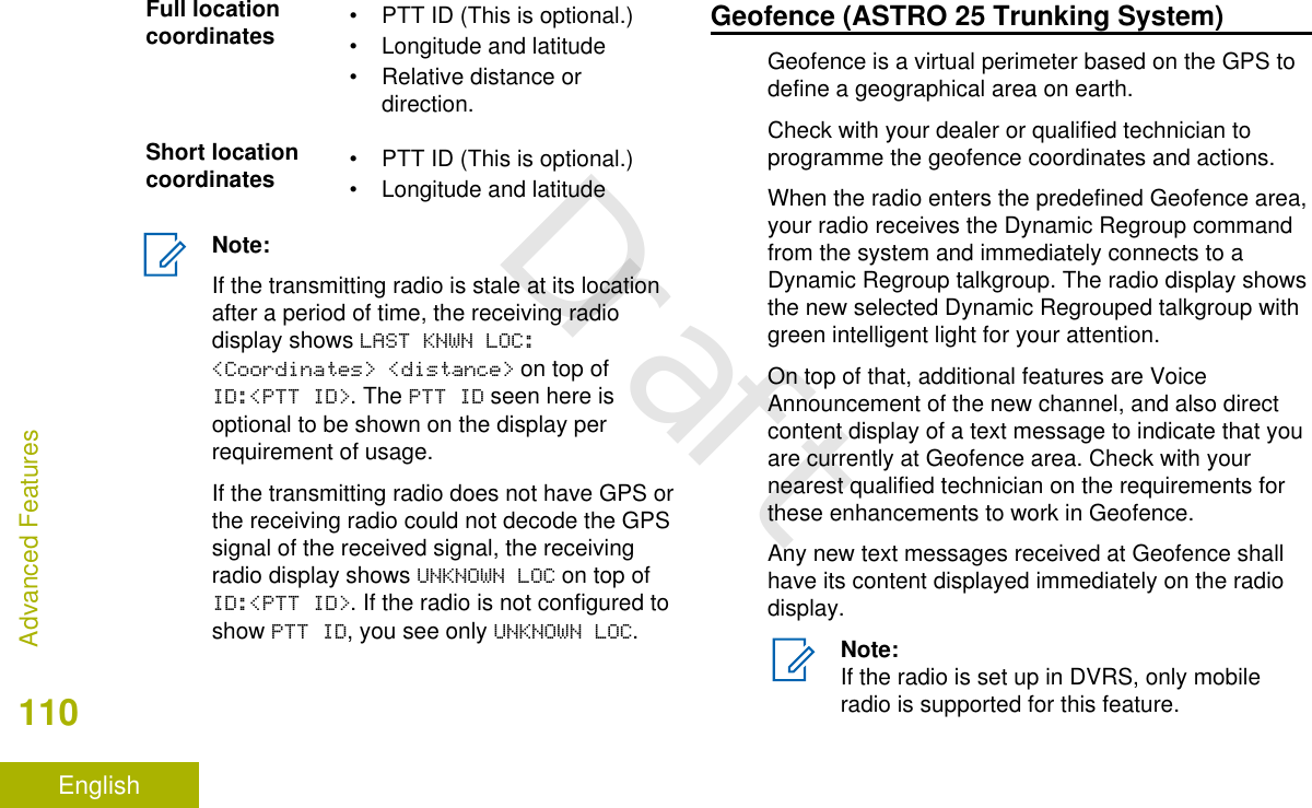
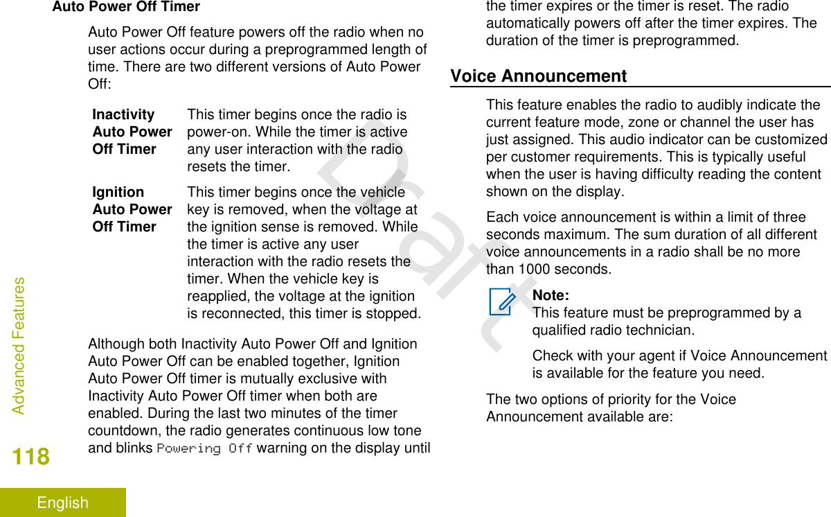
![Identifying Radio ControlsRadio Parts and ControlsControl Head and Microphone1 68101213141516 119723451718 20212219Note:The microphone is not part of a radio. It is anoptional accessory.1 Accessory Port (Microphone)2 Menu Select Button[1]3 Menu Entries4 LED Indicators5 Navigation Button6 Accy 2-Dot Button[1]7 Accy 1-Dot Button[1]Identifying Radio Controls22EnglishDraft](https://usermanual.wiki/Motorola-Solutions/92FT7118.Users-Guide/User-Guide-3957955-Page-24.png)
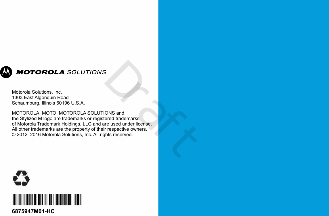
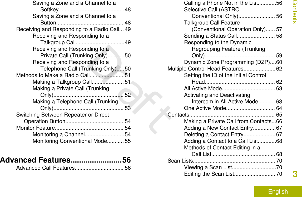
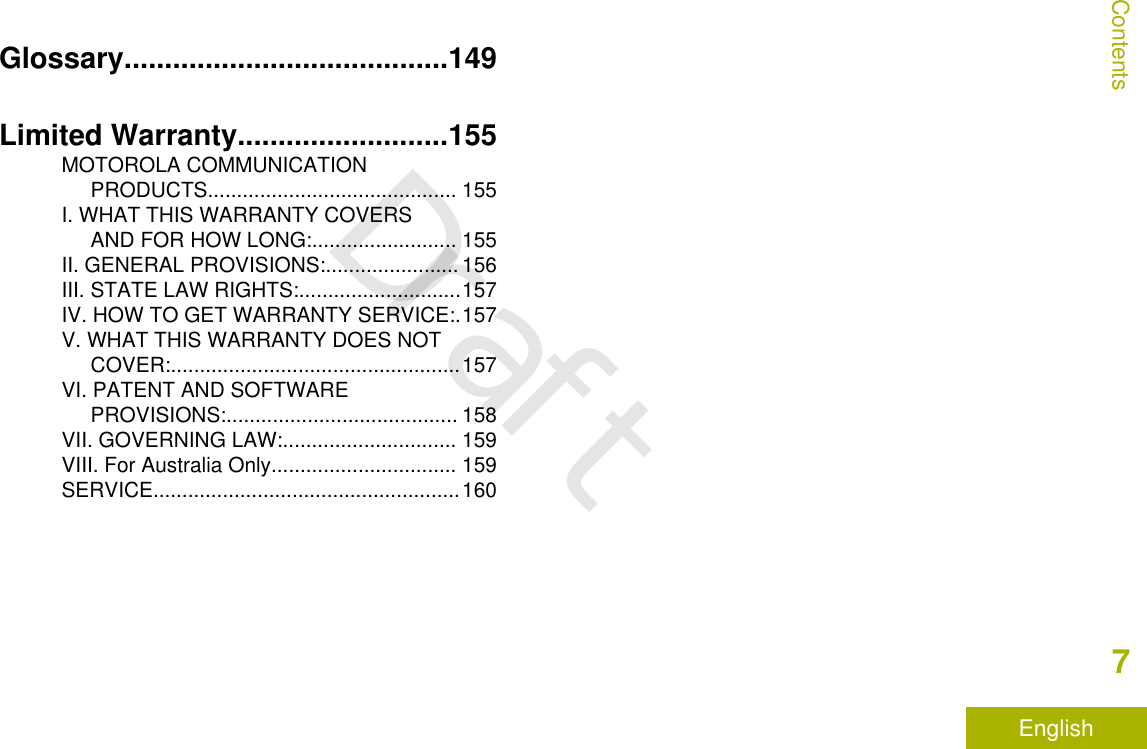
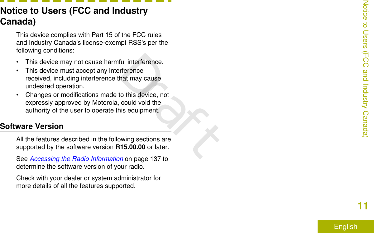
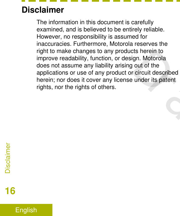
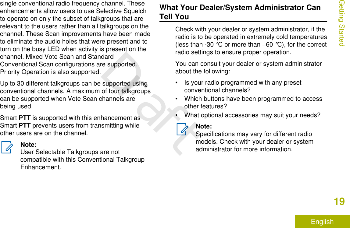
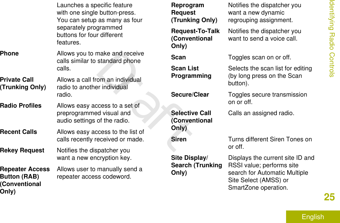
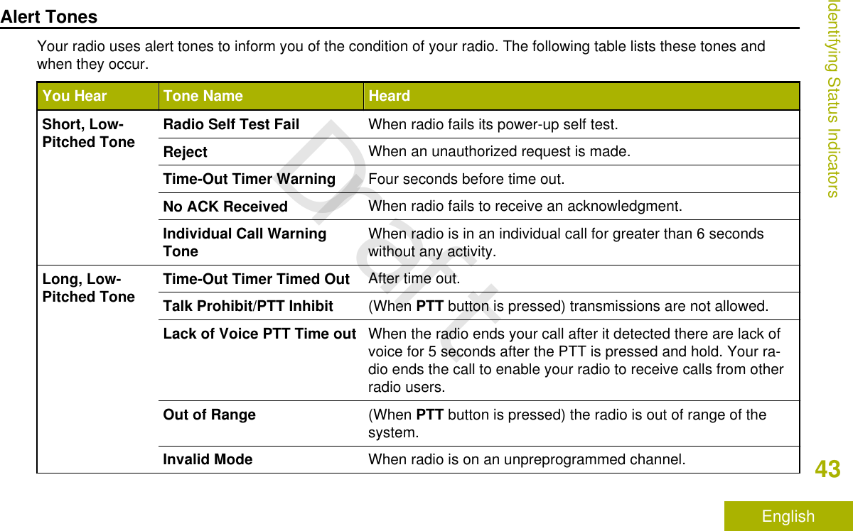
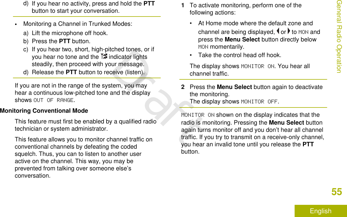
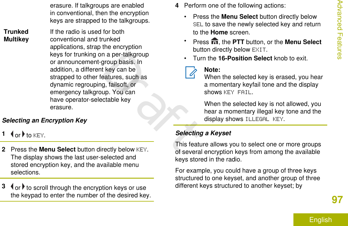
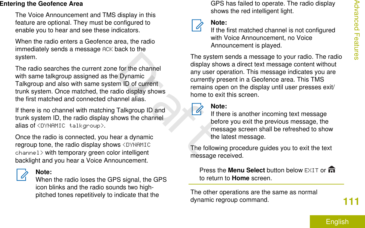
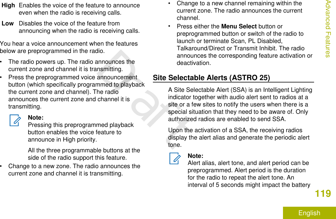
![8 Accy No-Dot Button (Purple)[1]9 Push-to-Talk (PTT) Button10 Orange Button[1]11 Mode Knob12 Indicators13 Power On/Off Button14 Home Button15 Dim Button16 Volume Knob17 Data Feature Button[1]18 Home Button (Microphone)19 Keypad Buttons20 Okay/Select Button ( )21 Cancel Button (X)22 Navigation Button (Microphone)Programmable FeaturesAny reference in this manual to controls that arepreprogrammed means that a qualified radiotechnician must use the radio programming softwareto assign a feature to a control.Your dealer can program the programmable buttonsas shortcuts to radio functions or preset channels/groups depending on the duration of a button press:Press Pressing and releasing rapidly.Long press Pressing and holding for thepreprogrammed duration (between0.25 seconds and 3.75 seconds).Hold down Keeping the button pressed.Assignable Radio FunctionsCall Alert Allows the radio to function likea pager, or to verify if a radio isactive on the system.1These radio controls/buttons are programmable.Identifying Radio Controls23EnglishDraft](https://usermanual.wiki/Motorola-Solutions/92FT7118.Users-Guide/User-Guide-3957955-Page-25.png)
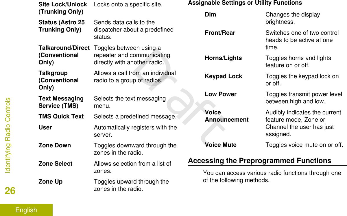
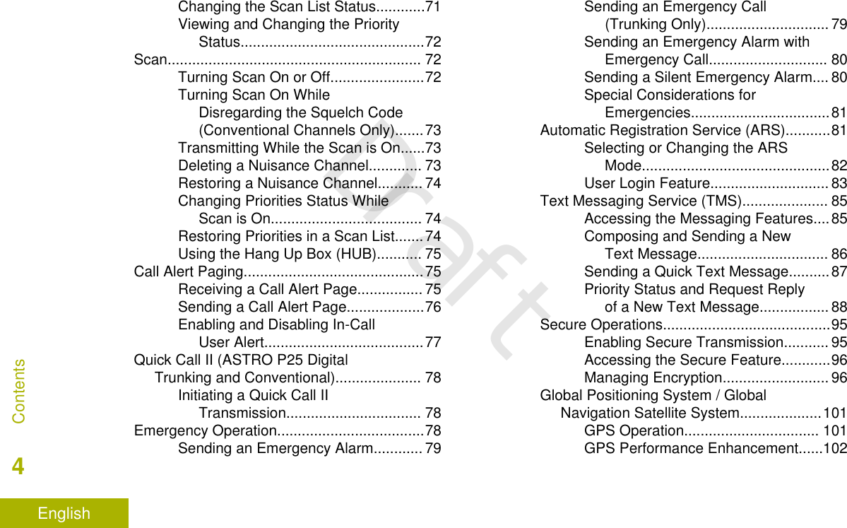
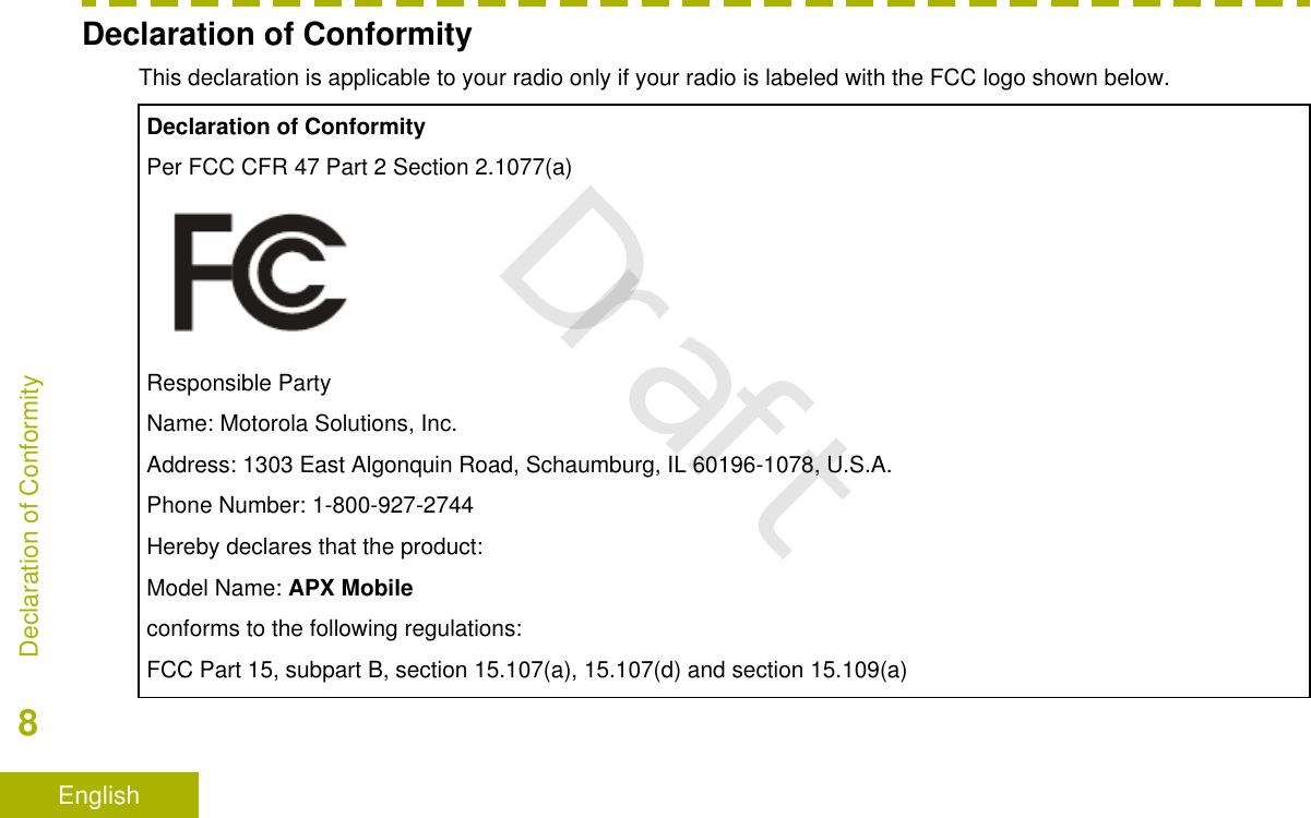
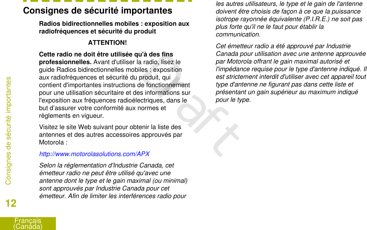
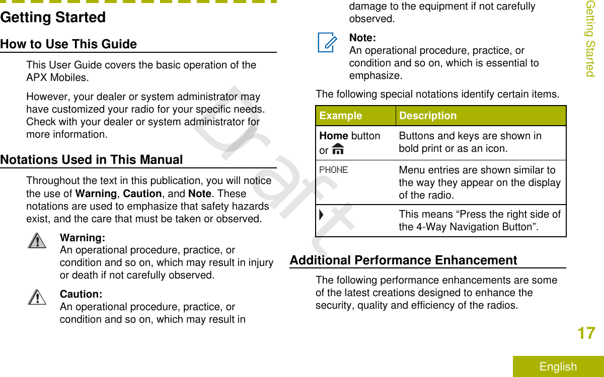
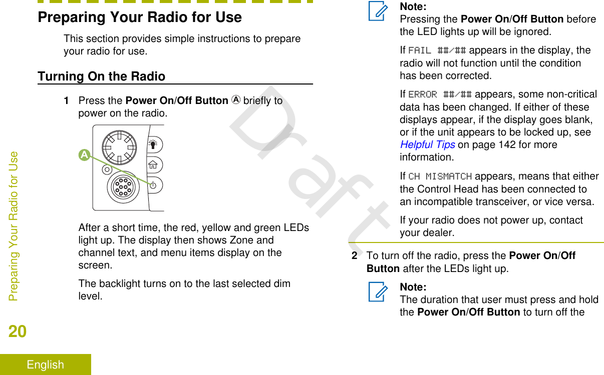
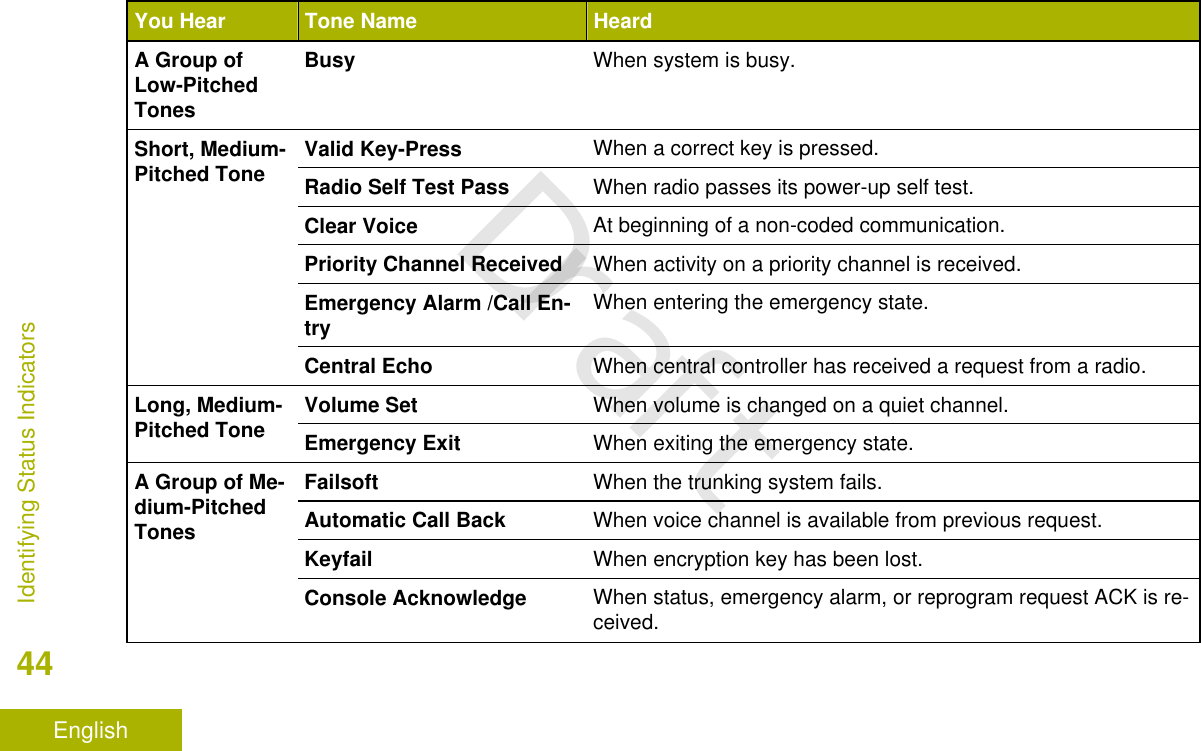
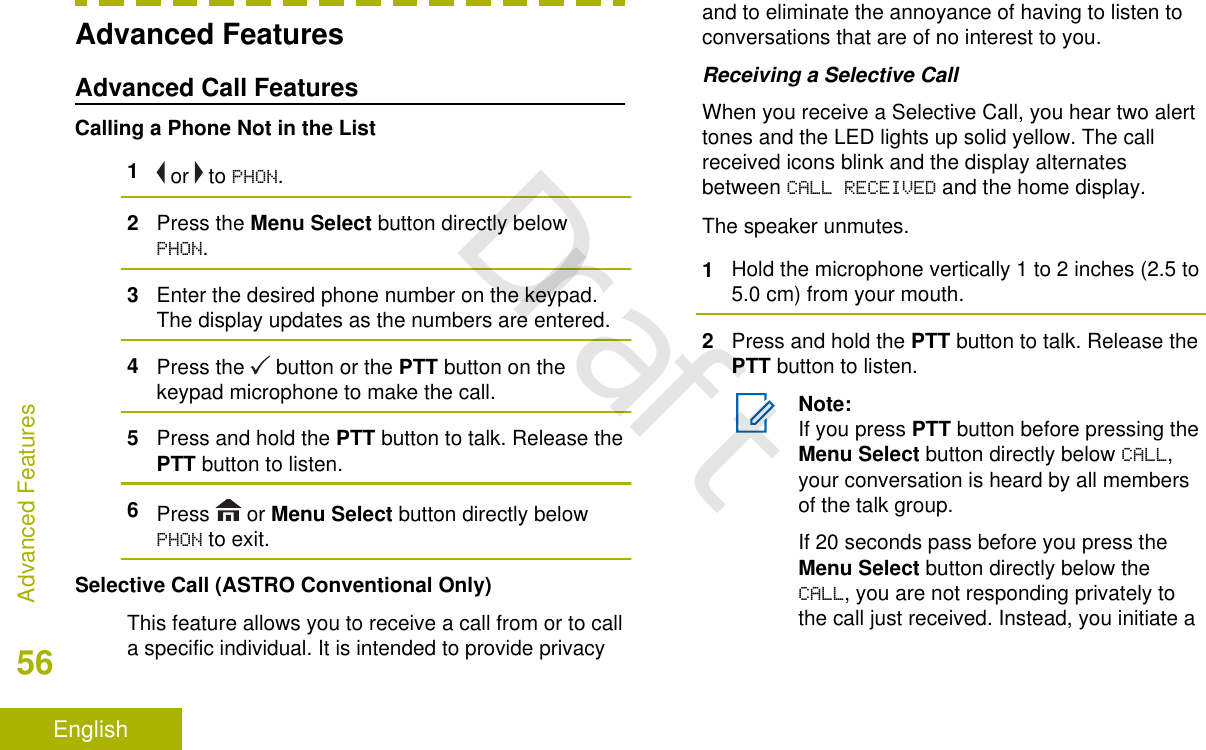
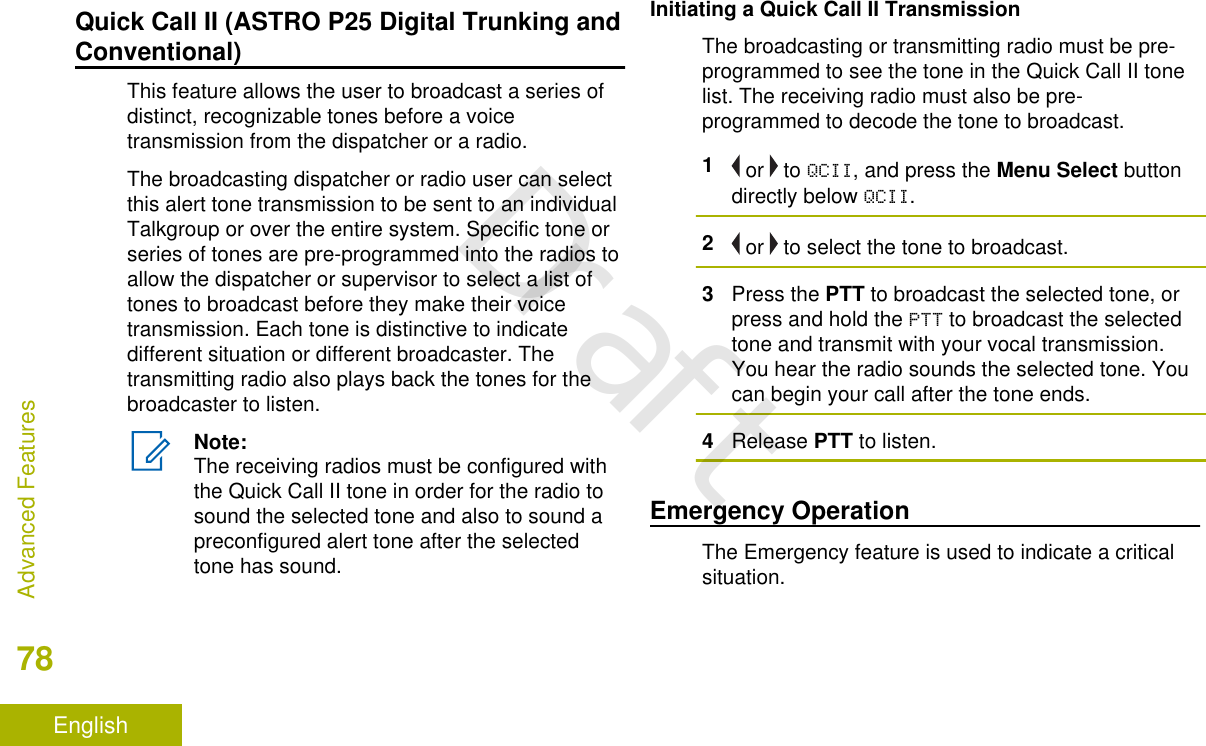
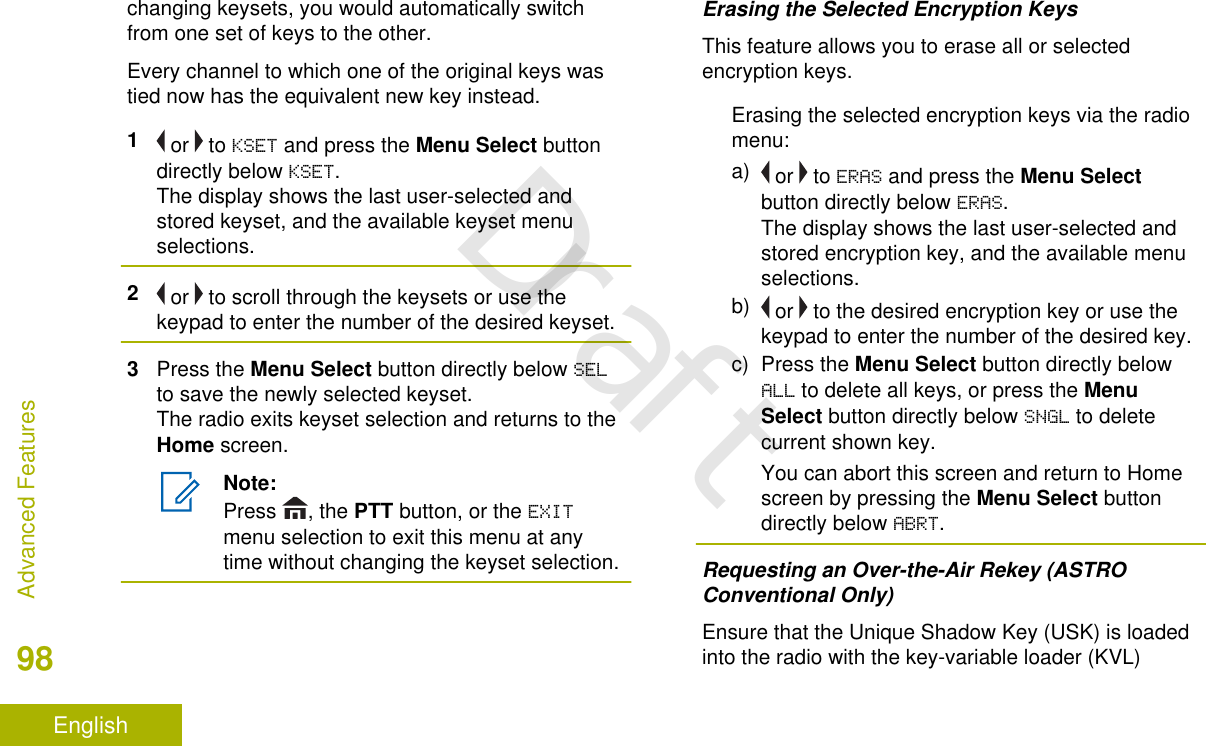
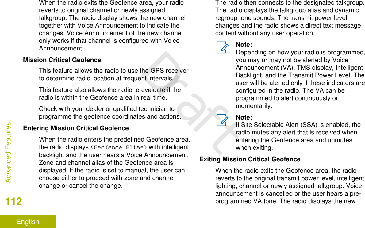
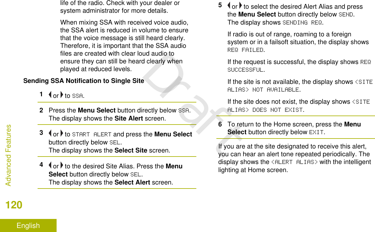
![•A short or long press of the relevantprogrammable buttons.•Use the Menu Select Button ( ).Menu Select ButtonsNote:Check with your dealer or systemadministrator for the list of features activatedin your radio.Use the Menu Select button to access the menuentry of your radio feature. Your radio may bepreprogrammed differently from the followingexample, but the steps for selecting a channel mayappear as shown below:Press the Menu Select button ( ) directly belowCHAN.AAdvance Programmable ButtonsThis feature is to help you to shorten the process ofapplying certain common features.CBADEAOrange Button[2]BMenu Select Buttons[2]Identifying Radio Controls27EnglishDraft](https://usermanual.wiki/Motorola-Solutions/92FT7118.Users-Guide/User-Guide-3957955-Page-29.png)
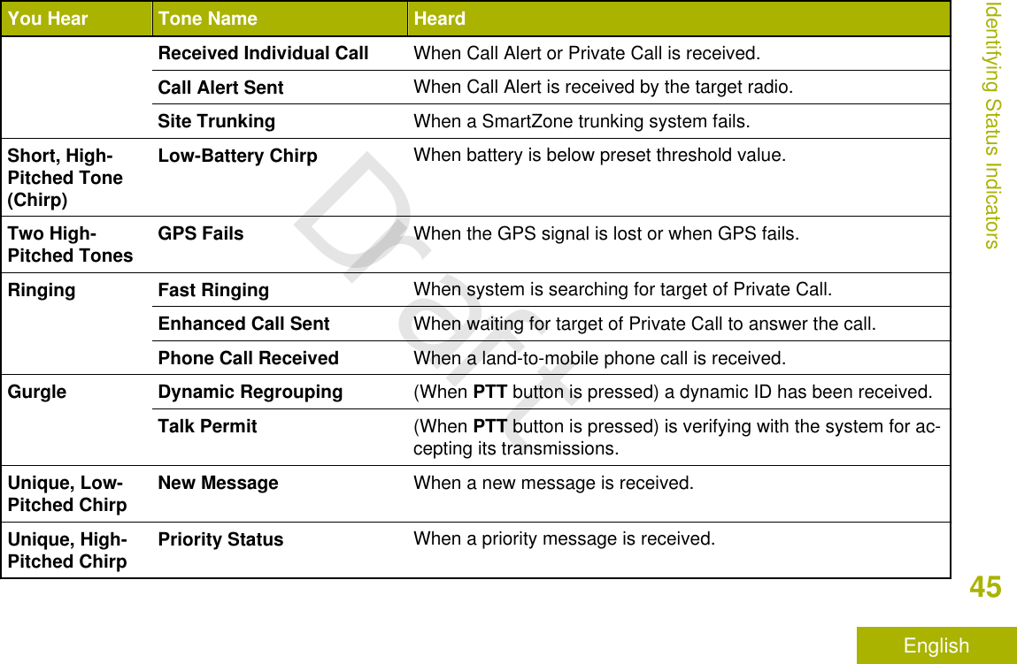
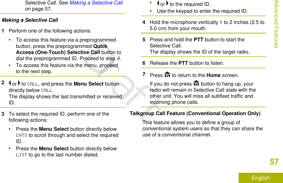
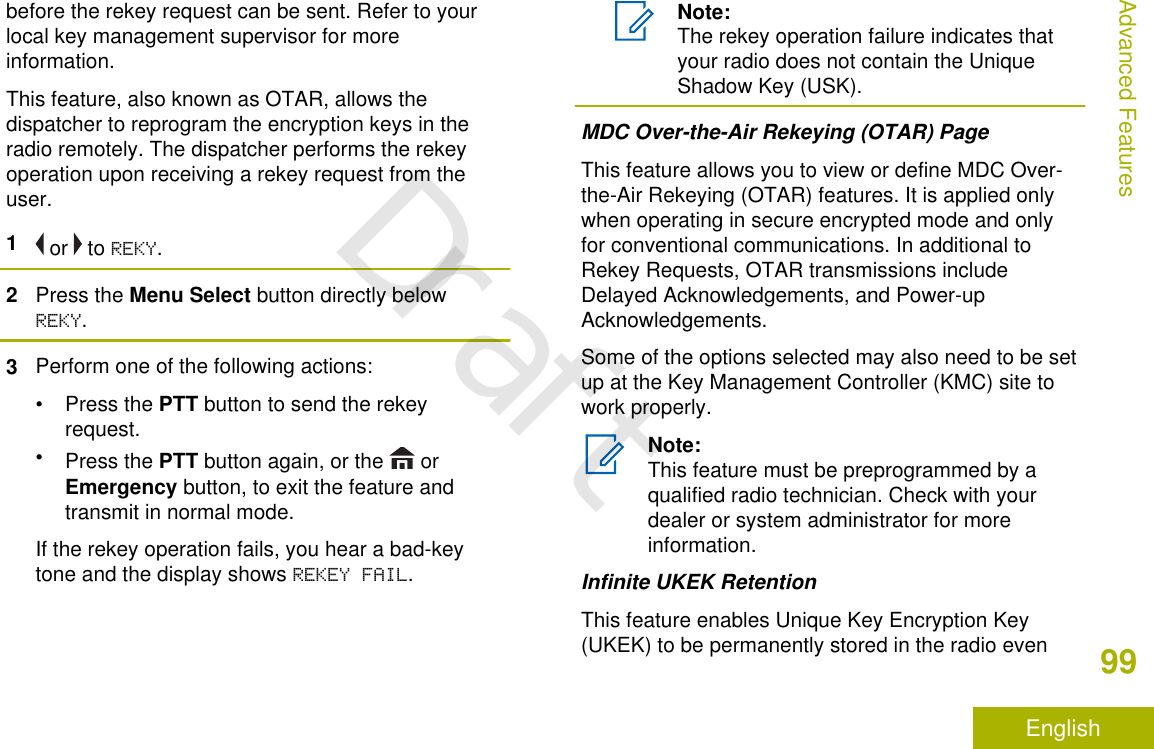
![CAccy No-Dot Button (Purple)[2]DAccy 1-Dot Button[2]EAccy 2-Dot Button[2](QuickAccess)One TouchButtonEnters a menu with a short press onthe preprogrammed One Touchbutton. Features assigned to thesebuttons are Call, Call Alert, Phone,Repeater Access, MDC RTT ButtonAccess, Status and Message.Home ButtonPressing the button returns you to the Home(default) screen. In most cases, this is the currentmode. For selected radio features, the button isalso used to save user-edited radio settings orinformation before returning you to the Home screen.Note:Some features do not require you to press to go to the Home screen. Refer to theindividual feature sections in this manual forfurther details on saving user-edited radiosettings or information.The button also can revert to home channel fromany other zone and mode in the radio. Check withyour dealer or system administrator for moreinformation.4-Way Navigation ButtonUse the 4-Way Navigation Button to scroll up, down,left or right with one of the following methods.• Press and release one of the button to scroll fromone entry to the next one.• Press and hold one of the button to have the radiotoggles through the list automatically (release thebutton to stop).Data Feature ButtonUse Data Feature button to access data-relatedfeatures, such as the Text Messaging Service (TMS)feature screen.2These programmable buttons support the One Touch Button feature.Identifying Radio Controls28EnglishDraft](https://usermanual.wiki/Motorola-Solutions/92FT7118.Users-Guide/User-Guide-3957955-Page-30.png)
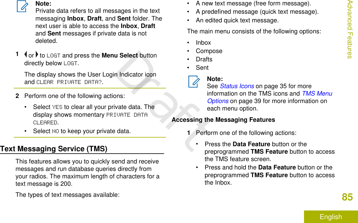
![Adding a New Contact Entry1 or to CNTS and press the Menu Select buttondirectly below CNTS.The entries are alphabetically sorted.2 or to [NEW CONTACT] and press the MenuSelect button directly below SEL.The display shows NAME.3Press the Menu Select button directly belowEDIT.4Use the keypad to enter the name and press theMenu Select button directly below OK once youhave entered the name.To cancel this operation, press the Menu Selectbutton directly below CNCL to return to the previousscreen.5 or to [ADD NUMBER] and press the MenuSelect button directly below SEL.The display shows TYPE 1 <DEFAULT TYPE>.6Press the Menu Select button directly belowEDIT.7 or to the required channel and press the MenuSelect button directly below OK.8 or to NUMBER 1 and press the Menu Selectbutton directly below EDIT.The display shows NUMBER 1 and a blinking cursorappears.9Use the keypad to enter the number and pressthe Menu Select button directly below OK onceyou have entered the number.To cancel this operation, press the Menu Selectbutton directly below CNCL to return to the previousscreen.10 Press the Menu Select button directly below DONEonce you have finished.The display shows <ENTRY> STORED, confirmingthat the contact entry has been added.The radio returns to the main Contacts screen.Deleting a Contact Entry1 or to CNTS and press the Menu Select buttondirectly below CNTS.Advanced Features67EnglishDraft](https://usermanual.wiki/Motorola-Solutions/92FT7118.Users-Guide/User-Guide-3957955-Page-69.png)
![The entries are alphabetically sorted.2 or to the entry you want to delete and press theMenu Select button directly below OPTN.3 or to DEL and press the Menu Select buttondirectly below SEL.The display shows <ENTRY> CONFIRM DEL?.4Select the Menu Select button directly below YESto delete the entry, or NO to cancel and return tothe main screen of Contacts.The display shows <ENTRY> DELETED and theradio returns to the main screen of Contacts.Adding a Contact to a Call List1 or to CNTS and press the Menu Select buttondirectly below CNTS.The entries are alphabetically sorted.2 or to the entry you want to add and press theMenu Select button directly below OPTN.3 or to ADD TO CALLLST or ADD TO PHONLSTand press the Menu Select button directly belowSEL.4Perform one of the following actions:• or until the display shows [AVAILABLE] andpress the Menu Select button directly belowADD to add as a new entry.• or until the display shows <ENTRY> and itsassociated number and press the Menu Selectbutton directly below RPLC to replace theexisting entry.The display shows <ENTRY> ADDED, confirmingthe addition of the contact to the list.The radio returns to the main display of Contacts.Methods of Contact Editing in a Call ListEditing an Entry Alias1 or to CNTS and press the Menu Select buttondirectly below CNTS.The entries are alphabetically sorted.Advanced Features68EnglishDraft](https://usermanual.wiki/Motorola-Solutions/92FT7118.Users-Guide/User-Guide-3957955-Page-70.png)
![• In ARS Non-Server Mode, the displayshows the User Login Indicator icon, thezone, and ARS non-server channel.• If the channel or mode selected isunprogrammed, the display showsUNPROGRAMMED. Repeat this step.c) Press to confirm the displayed zone andchannel.User Login FeatureThis feature allows you as the user to be associatedwith the radio. With this association, every dataapplication (Example: Text Messaging Service) takeson a friendly username.You can still send text messages without logging in asa user. The user login feature only enables therecipient of your message to identify you as thesender by assigning a username to your message.Note:Valid characters for a username entry arecapital letters (A – Z), small letters (a – z),numbers (0 – 9), symbols (*, #, -, /), and thespace character.The maximum length for a username is eight(8) characters. Usernames are not casesensitive in server mode but are casesensitive in non-server mode.A predefined username may sometimes beinvalid because the programming softwarethat is used to set predefined usernamesallows you to set usernames comprising ofeight (8) characters or more.Logging In as a User1 or to USER and press the Menu Select buttondirectly below USER.The display shows the User Login screen.2Perform one of the following actions:• or to [ID Entry] and press the MenuSelect button directly below Edit to enter ID. Ablinking cursor appears on the screen. Use thekeypad to type or edit a user name. Press theMenu Select button directly below Ok tosubmit.• or to scroll through the list of predefineduser names. Press the Menu Select buttonAdvanced Features83EnglishDraft](https://usermanual.wiki/Motorola-Solutions/92FT7118.Users-Guide/User-Guide-3957955-Page-85.png)
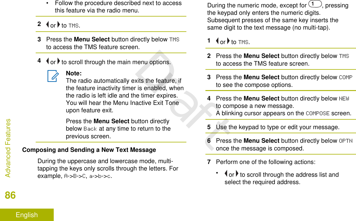
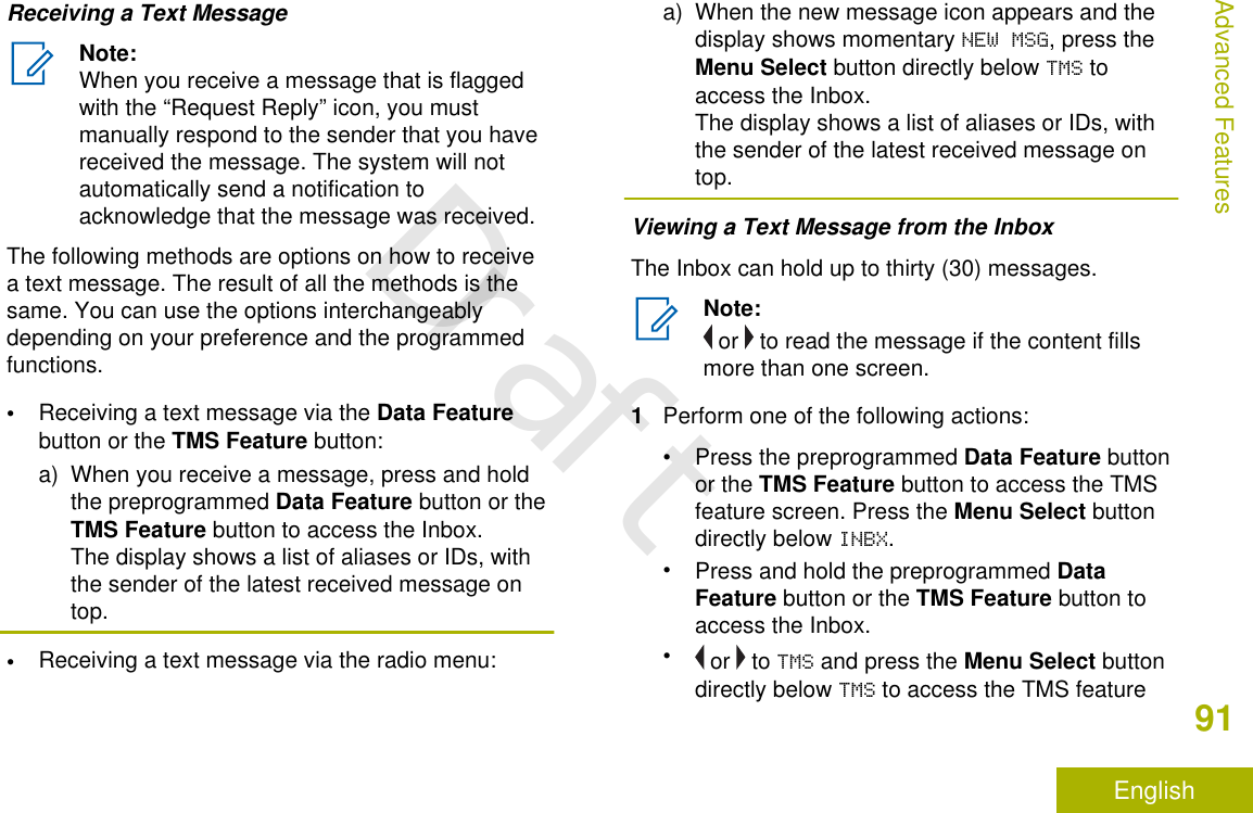
![• or to [OTHER RECPNT] and press the MenuSelect button below EDIT. When a blinkingcursor appears in the ENTER ADDRESS screen,use the keypad to type the address entry.8Press the Menu Select button directly below SENDor press the PTT button to send the message.The display shows the SEND MESSAGE screen andSENDING MSG.If the message is sent, you hear a tone and thedisplay shows MSG SENT.If the message is not sent, you hear a low tone,the display shows SEND FAILED and returns to themain TMS screen.Note:You can append a priority status and/or arequest reply to your message. See PriorityStatus and Request Reply of a New TextMessage on page 88 for moreinformation.You can also select the DRFT option tosave your message in the Drafts folder tosend it at a later time. See Accessing theDrafts Folder on page 93 for moreinformation.Sending a Quick Text MessageQuick Text messages are messages that arepredefined and usually consist of messages that areused most frequently.Each Quick Text message has a maximum length of50 characters.1Perform one of the following actions:• To access this feature via a preprogrammedbutton, press the preprogrammed Quick Textbutton and proceed to Step 4.• To access this feature via the menu, proceedto the next step.2 or to TMS and press the Menu Select buttondirectly below TMS to access the TMS featurescreen.3Perform one of the following actions:•Press the Menu Select button directly belowCOMP to see the compose options.Advanced Features87EnglishDraft](https://usermanual.wiki/Motorola-Solutions/92FT7118.Users-Guide/User-Guide-3957955-Page-89.png)
![•Press the Menu Select button directly belowEXIT to return to the Home screen.4Press the Menu Select button directly below LISTto see the quick text list.5 or to scroll through the list of messages andpress the Menu Select button directly below SELto select the required message.The message appears on the COMPOSE screen,with a blinking cursor at the end of it. Use thekeypad to edit the message, if required.6Press the Menu Select button directly belowOPTN.7Press the Menu Select button directly belowSEND.8Perform one of the following actions:• or to scroll through the address list andselect the required address.• or to [OTHER RECPNT] and press the MenuSelect button below EDIT. When a blinkingcursor appears on the ENTER ADDRESS screen.Use the keypad to type the address entry.9Press the Menu Select button directly below SENDor press the PTT button to send the message.The display shows the SEND MESSAGE screen andSENDING MSG.If the message is sent, you hear a tone and thedisplay shows MSG SENT.If the message is not sent, you hear a low tone,the display shows SEND FAILED and returns to themain TMS screen.Note:You can append a priority status and/or arequest reply to your message. See PriorityStatus and Request Reply of a New TextMessage on page 88 for moreinformation.Priority Status and Request Reply of a New TextMessageBefore sending your message, you can append apriority status and/or a request reply to your message.Advanced Features88EnglishDraft](https://usermanual.wiki/Motorola-Solutions/92FT7118.Users-Guide/User-Guide-3957955-Page-90.png)
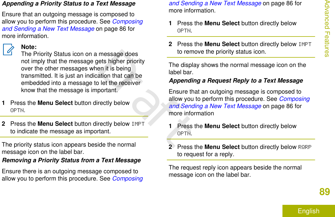
![• or to TMS and press the Menu Select buttondirectly below TMS to access the TMS featurescreen.2Press the Menu Select button below SENT.The display shows the latest sent message.3While on the view message screen, press theMenu Select button directly below OPTN, DEL orBACK to access the option.• Select OPTN to configure the message settings.• Select DEL to delete the message.• Select BACK to return to the previous screen.Note:The icon at the top right corner of thescreen indicates the status of the message.See Text Messaging Service (TMS)Indicators on page 38 for more information.Sending a Sent Text Message1Press the Menu Select button directly below OPTNwhile viewing the message.2Press the Menu Select button directly belowSEND.3Perform one of the following actions:• or to scroll through the address list andselect the required address.• or to [OTHER RECPNT] and press the MenuSelect button below EDIT. When a blinkingcursor appears in the ENTER ADDRESS screen,use the keypad to type the address entry.4Press the Menu Select button below SEND or thePTT button to send the message.The display shows the SEND MESSAGE screen andSENDING MSG.Note:Press the Menu Select button directlybelow BACK at any time to return to theprevious screen.You can append a priority status and/or arequest reply to your message. See PriorityStatus and Request Reply of a New TextMessage on page 88 for more information.Advanced Features94EnglishDraft](https://usermanual.wiki/Motorola-Solutions/92FT7118.Users-Guide/User-Guide-3957955-Page-96.png)
![A blinking cursor appears in the EDIT NAMEscreen.5Use the keypad to edit the alias.6Perform one of the following actions:•Press the Menu Select button directly belowOK once you are done.•Press the Menu Select button directly belowCNCL to return to the Waypoints main screen.7The display shows <WAYPOINT NAME> UPDATEDand the radio returns to the Waypoints mainscreen.8Perform one of the following actions:•Press the Menu Select button directly belowBACK to return to the previous screen.•Press or the PTT button to return to theHome screen.Editing the Coordinates of a WaypointNote:Only the preprogrammed coordinates of Homeand Destination can be edited by the user.Ensure your radio shows the current location on thescreen.1Press the Menu Select button directly belowOPTN.2 or to WAYPOINTS and press the Menu Selectbutton directly below SEL.The display shows a list of waypoints.3Perform one of the following actions:•or to [HOME] and press the Menu Selectbutton directly below OPTN.•or to [DESTINATION] and press the MenuSelect button directly below OPTN.4 or to EDIT LOCATION and press the MenuSelect button directly below SEL.The first number blinks.5Utilize the following control buttons to select thenumber/coordinates if required, then press theMenu Select button directly below EDIT to changethe number/coordinates.Advanced Features106EnglishDraft](https://usermanual.wiki/Motorola-Solutions/92FT7118.Users-Guide/User-Guide-3957955-Page-108.png)
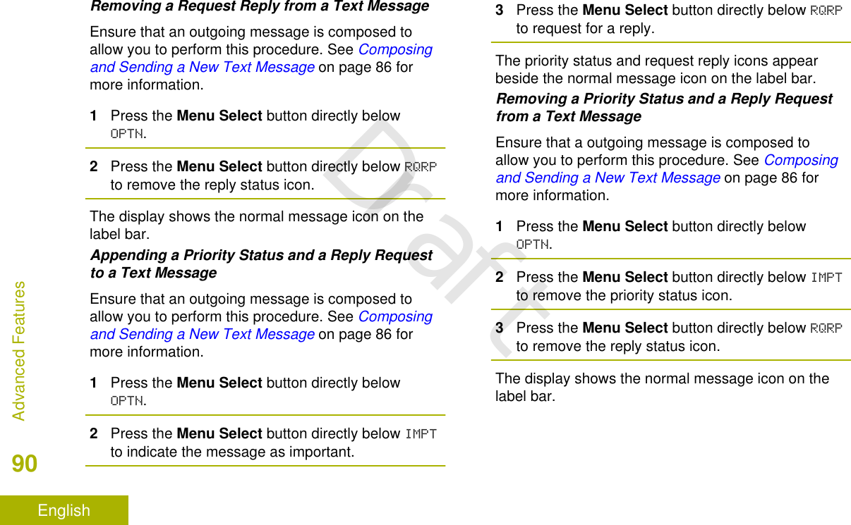
![•Press to move to the previous number/coordinates.•Press to move to the next number/coordinates.• Press or to change the North (N), South(S), East (E) or West (W) direction.A blinking cursor appears in the EDIT LOCATIONscreen.6Utilize the following control buttons or menu tochange the number/coordinates if required thenpress the Menu Select button directly below OKonce.•Press to move one space to the left.•Press to move one space to the right.•Press the Menu Select button directly belowDEL to delete any unwanted characters.•Press the Menu Select button directly belowCNCL to return to the previous screen7Press the Menu Select button directly below OKonce complete setting up the new Home orDestination.One of the following scenarios occurs:• The display shows [HOME] UPDATED and theradio returns to the Waypoints main screen.• The display shows [DESTINATION] UPDATEDand the radio returns to the Waypoints mainscreen.Deleting a Single Saved WaypointEnsure your radio shows the current location on thescreen.1Press the Menu Select button directly belowOPTN.2 or to WAYPOINTS and press the Menu Selectbutton directly below SEL.The display shows a list of waypoints.3Perform one of the following actions:• or to the required saved waypoint, andpress the Menu Select OPTN. or to Editname and press the Menu Select buttondirectly below Del.•Press the Menu Select button directly belowDel.Advanced Features107EnglishDraft](https://usermanual.wiki/Motorola-Solutions/92FT7118.Users-Guide/User-Guide-3957955-Page-109.png)
![Sending SSA Notification to Single Site Via ManualEntry1 or to SSA.2Press the Menu Select button directly below SSA.The display shows the Site Alert screen.3 or to START ALERT and press the Menu Selectbutton directly below SEL.The display shows the Select Site screen.4 or to [SITEID ENTRY] to send alert via manualentry. Press the Menu Select button directlybelow EDIT.The display shows the Enter SiteID screen.5Key in the desired Site ID and press the MenuSelect button directly below OK.If a correct Site ID is entered, the display showsthe Select Alert screen.If a wrong Site ID is entered, the display showsINVALID ID and prompts to enter the Site IDagain.6 or to select the desired Alert Alias and pressthe Menu Select button directly below SEND.The display shows SENDING REQ.If radio is out of range, roaming to a foreignsystem or in a failsoft situation, the display showsREQ FAILED.If the request is successful, the display shows REQSUCCESSFUL.If the site is not available, the display shows <SITEID> NOT AVAILABLE.If the site does not exist, the display shows <SITEID> DOES NOT EXIST.7To return to the Home screen, press the MenuSelect button directly below EXIT.If you are at the site designated to receive this alert,you can hear an alert tone repeated periodically. Thedisplay shows the <ALERT ALIAS> with the intelligentlighting at Home screen.Sending SSA Notification to All Sites1 or to SSA.Advanced Features121EnglishDraft](https://usermanual.wiki/Motorola-Solutions/92FT7118.Users-Guide/User-Guide-3957955-Page-123.png)
![2Press the Menu Select button directly below SSA.The display shows the Site Alert screen.3 or to START ALERT and press the Menu Selectbutton directly below SEL.The display shows the Select Site screen.4 or to [All SITES] and press the Menu Selectbutton directly below SEL.The display shows the Select Alert screen.5 or to select the desired <Alert Alias> andpress the Menu Select button directly below SEND.The display shows SENDING REQ.If radio is out of range, roaming to a foreignsystem or in a failsoft situation, the display showsREQ FAILED.If the request is successful, the display shows REQSUCCESSFUL.If one or more sites are unavailable, the displayshows NOT ALL SITES AVAILABLE. Repeat 3.6To return to the Home screen, press the MenuSelect button directly below EXIT.If you are at the site designated to receive this alert,you can hear an alert tone repeated periodically. Thedisplay shows the <ALERT ALIAS> with the intelligentlighting at Home screen.Sending SSA Notification to All Available Sites1 or to SSA.2Press the Menu Select button directly below SSA.The display shows the Site Alert screen.3 or to START ALERT and press the Menu Selectbutton directly below SEL.The display shows the Select Site screen.4 or to [All AVAIL] and press the Menu Selectbutton directly below SEL.The display shows the Select Alert screen.5 or to select the desired <Alert Alias> andpress the Menu Select button directly below SEND.The display shows SENDING REQ.If radio is out of range, roaming to a foreignsystem or in a failsoft situation, the display showsREQ FAILED.Advanced Features122EnglishDraft](https://usermanual.wiki/Motorola-Solutions/92FT7118.Users-Guide/User-Guide-3957955-Page-124.png)
![The display shows the Select Site screen.4 or to [SITEID ENTRY] and press the MenuSelect button directly below EDIT.The display shows the Enter SiteID screen.5Key in the required Site ID and press the MenuSelect button directly below SEND.One of the following scenarios occur:• If a wrong Site ID is entered, the display showsINVALID ID and prompts to enter the Site IDagain.• If a correct Site ID is entered, the displayshows SENDING REQ.• If the request is successful, the display showsREQ SUCCESSFUL.• If the single site is not available, the displayshows <SITE ID> NOT AVAILABLE.• If the single site does not exist, the displayshows <SITE ID> DOES NOT EXIST.6To return to the Home screen, press the MenuSelect button directly below EXIT.The SSA Alert for the designated site stops.Stopping SSA Notification of All Sites1 or to SSA.2Press the Menu Select button directly below SSA.The display shows the Site Alert screen.3 or to STOP ALERT and press the Menu Selectbutton directly below SEL.The display shows the Select Site screen.4 or to [ALL SITES] and press the Menu Selectbutton directly below SEND.The display shows SENDING REQ.If radio is out of range, roaming to a foreignsystem or in a failsoft situation, the display showsREQ FAILED.If the request is successful, the display shows REQSUCCESSFUL.If one or more sites are not available, the displayshows NOT ALL SITES AVAILABLE. Repeat step 3.5To return to the Home screen, press the MenuSelect button directly below EXIT.Advanced Features124EnglishDraft](https://usermanual.wiki/Motorola-Solutions/92FT7118.Users-Guide/User-Guide-3957955-Page-126.png)
![The SSA Alert for all sites stop.Stopping SSA Notification of All Available Sites1 or to SSA.2Press the Menu Select button directly below SSA.The display shows the Site Alert screen.3 or to STOP ALERT and press the Menu Selectbutton directly below SEL.The display shows the Select Site screen.4 or to [All AVAIL] and press the Menu Selectbutton directly below SEND.The display shows SENDING REQ.If radio is out of range, roaming to a foreignsystem or in a failsoft situation, the display showsREQ FAILED.If the request is successful, the display shows REQSUCCESSFUL.5To return to the Home screen, press the MenuSelect button directly below EXIT.The SSA Alert for all available sites stop.Channel Change on Off Hook on All ChannelsThis feature enables the mode of the radio to bechanged based on the HUB on/off-hook state on allcontrol heads.Whenever the radio goes off-hook, the radio changesto a preprogrammed zone channel specifically for off-hook state. When the user returns the radio to on-hook state, it reverts to its previous channel zonebefore the radio goes off-hook.When the radio is in off-hook state, manual modechange (including mode change triggered by thirdparty devices) is allowed. Radio reverts back to thelast mode before off-hook once the radio goes on-hook.Note:During PL Defeats and Suspend Scan duringon-hook state, the radio is converted to workin new channel and Channel Change on OffHook feature is suspended until theseconditions end.We do not recommend that “Hub SuspendScan" and "Channel Change on Off Hook" tobe enabled simultaneously.Advanced Features125EnglishDraft](https://usermanual.wiki/Motorola-Solutions/92FT7118.Users-Guide/User-Guide-3957955-Page-127.png)
![normal, the external device de-asserts the VIP inputto the radio.The voltage threshold is customized in the externaldevice settings.When the VIP switch turns on, the VIP asserts inputto the radio. The radio immediately initiates a 15seconds of low Voltage Pre-alert Timer. If the statusof the VIP changed before this time-out timer ends,the radio returns to normal operation.If the status from the VIP unchanged when the time-out timer ends, the radio shows LOW BATTERY on thedisplay and also sounds low battery/voltage alerttone. The radio sounds a short, high-pitched toneimmediately after the PTT button is released.Note:If the mobile radio does not have a controlhead connected, the bricks can only alert theuser with battery alert tone and the transmitchirp.Wi-FiThis feature allows you to turn Wi-Fi® on or off. Wi-Fican be used for wireless programming of the radiowith the Radio Management tool. [3]Note:Wi-Fi Network Name (SSID) for the radio toconnect to must be preprogrammed by aqualified radio technician. Check with yourdealer or system administrator for moreinformationTurning Wi-Fi On or OffThe following methods are options on how to turn Wi-Fi® on or off. The result of all the methods is thesame. You can use the options interchangeablydepending on your preference and the programmedfunctions.•Turning Wi-Fi on or off via the preprogrammedbutton:3This feature is available to capable and ordered option.Advanced Features127EnglishDraft](https://usermanual.wiki/Motorola-Solutions/92FT7118.Users-Guide/User-Guide-3957955-Page-129.png)