Motorola Solutions 99FT4025 MOTOTRBO UHF 40W Transceiver/Repeater User Manual cy UG
Motorola Solutions, Inc. MOTOTRBO UHF 40W Transceiver/Repeater cy UG
Exhibit D Users Manual per 2 1033 c3
1
m
User Guide
XPR 8300 Repeater
Computer Software Copyrights
The Motorola products described in this manual may include copyrighted Motorola com-
puter programs stored in semiconductor memories or other media. Laws in the United
States and other countries preserve for Motorola certain exclusive rights for copyrighted
computer programs, including, but not limited to, the exclusive right to copy or repro-
duce in any form, the copyrighted computer program. Accordingly, any copyrighted
Motorola computer programs contained in the Motorola products described in this man-
ual may not be copied, reproduced, modified, reverse-engineered, or distributed in any
manner without the express written permission of Motorola. Furthermore, the purchase
of Motorola products shall not be deemed to grant, either directly or by implication,
estoppel or otherwise, any license under the copyrights, patents or patent applications
of Motorola, except for the normal non-exclusive license to use that arises by operation
of law in the sale of a product.

2
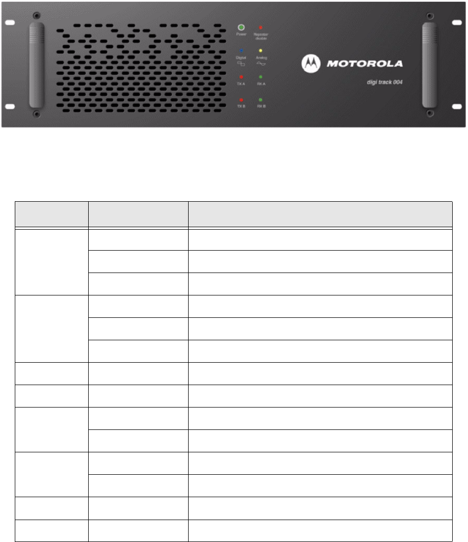
Repeater Front Panel
LED Indicator Descriptions
LED Status Description
Power Solid GREEN Repeater powered by AC
Solid RED Repeater powered by back-up battery
Off Repeater powered off
Repeater
Disable
Solid RED Repeat function disabled
Blinking RED Repeater in self test mode
Off Repeater in normal operational mode
Digital Solid BLUE Repeater in Digital mode
Analog Solid YELLOW Repeater in Analog More
TX-A Solid RED Repeater transmitting (Analog)
Solid RED Repeater transmitting on Slot A (Digital)
RX – A Solid GREEN Repeater receiving (Analog)
Solid GREEN Repeater receiving on Slot A (Digital)
TX – B Solid RED Repeater transmitting on Slot A (Digital)
RX – B Solid GREEN Repeater receiving on Slot A (Digital)

3
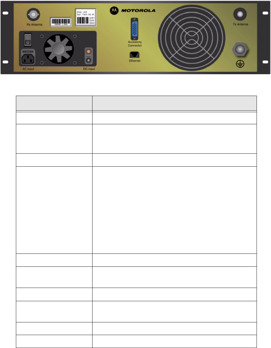
Repeater Rear Panel
Item Description
Rx Antenna Type BNC-F
Main Power Switch Turns on/off power to repeater from both AC input
and back-up battery. If switch is off Repeater will
not switch to Battery operation.
AC Input 117 - 230 Volts
DC Input Back-up battery supplies back-up power to
repeater. The battery is an optional accessory.
Repeater will trickle charge battery, but an external
charger is recommended to equalize battery after
prolonged use. Auto switching from AC to battery
with loss of AC power is a function or the standard
repeater power supply. Supply will automatically
switch back to AC operation upon return of AC
power. The Front Panel Power LED switches from
Green to Red when on Battery power
Power Supply Fan Runs continuously
Accessory Connector Programming cable plugs in here. Additional
future features will be provided on this port.
Ethernet Connector (Future Use)
Main Fan Variable speed. Idles at room temperature.
Speeds up with extended use of the repeater
TX Antenna Type N – F
GROUND Must be connected to System Ground
4
©2006 by Motorola, Inc. All rights reserved.
Motorola Technology Sdn. Bhd. (Co. No. 455657-H)
Plot 2 Bayan Lepas Technoplex Industrial Park
Mukim 12 S.W.D.
11900 Penang, Malaysia
Printed in Malaysia
March, 2006
*5480384S84*
number_rev