Motorola Solutions 99FT4091 UHF Portable radio User Manual MainContent NAG LACR
Motorola Solutions, Inc. UHF Portable radio MainContent NAG LACR
Contents
- 1. Users Guide
- 2. RF Safety Guide
RF Safety Guide

English
m
XPR 7550 Ex Digital Portable Radios
Quick Reference Guide
*68009584001*
68009584001-A

1English
RF ENERGY EXPOSURE AND
PRODUCT SAFETY GUIDE FOR
PORTABLE TWO-WAY RADIOS
ATTENTION! BEFORE USING THIS RADIO, READ
THIS GUIDE WHICH CONTAINS
IMPORTANT OPERATING
INSTRUCTIONS FOR SAFE USAGE
AND RF ENERGY AWARENESS AND
CONTROL FOR COMPLIANCE WITH
APPLICABLE STANDARDS AND
REGULATIONS.

2
English
RF Energy Exposure Awareness and
Control Information and Operational
Instructions for Occupational Use
NOTICE: This radio is intended for use in
occupational/controlled conditions
where users have full knowledge of their
exposure and can exercise control over
their exposure to meet the occupational
limits in FCC and International
standards. This radio device is NOT
authorized for general population
consumer use.
This two-way radio uses electromagnetic energy in
the radio frequency (RF) spectrum to provide
communications between two or more users over a
distance. It uses radio frequency (RF) energy or radio
waves to send and receive calls. RF energy is one
form of electromagnetic energy. Other forms include,
but are not limited to, sunlight and x-rays. RF energy,
however, should not be confused with these other
forms of electromagnetic energy, which when used
improperly, can cause biological damage. Very high
levels of x-rays, for example, can damage tissues and
genetic material.
Experts in science, engineering, medicine, health, and
industry work with organizations to develop standards
for safe exposure to RF energy. These standards
provide recommended levels of RF exposure for both
workers and the general public. These recommended
RF exposure levels include substantial margins of
protection.
All Motorola two-way radios are designed,
manufactured, and tested to ensure they meet
government-established RF exposure levels. In
addition, manufacturers also recommend specific

3English
operating instructions to users of two-way radios.
These instructions are important because they inform
users about RF energy exposure and provide simple
procedures on how to control it.
Please refer to the following websites for more
information on what RF energy exposure is and how
to control your exposure to assure compliance with
established RF exposure limits:
http://www.fcc.gov/oet/rfsafety/rf-faqs.html
www.who.int/en/
www.motorolasolutions.com/rfhealth
Federal Communication Commission
(FCC) Regulations
When two-way radios are used as a consequence of
employment, the FCC requires users to be fully aware
of and able to control their exposure to meet
occupational requirements. Exposure awareness can
be facilitated by the use of a product label directing
users to specific user awareness information. Your
Motorola two-way radio has a RF Exposure Product
Label. Also, your Motorola user manual, or separate
safety booklet includes information and operating
instructions required to control your RF exposure and
to satisfy compliance requirements.
Compliance with RF Exposure Standards
Your Motorola two-way radio is designed and tested to
comply with a number of national and International
standards and guidelines (listed below) for human
exposure to radio frequency electromagnetic energy.
This radio complies with the IEEE (FCC) and
ICNIRP exposure limits for occupational/
controlled RF exposure environments at

4
English
operating duty factors of up to 50% talk-50% listen
and is approved for occupational use only. In
terms of measuring RF energy for compliance with
these exposure guidelines, your radio generates
measurable RF energy only while it is transmitting
(during talking), not when it is receiving (listening)
or in standby mode.
NOTE: The approved batteries, supplied with this
radio, are rated for a 5-5-90 duty factor (5%
talk-5% listen-90% standby) even though this
radio complies with FCC occupational
exposure limits and may operate at duty
factors of up to 50% talk.
Your Motorola two-way radio complies with the
following RF energy exposure standards and
guidelines:
• United States Federal Communications
Commission (FCC), Code of Federal Regulations;
47 CFR et seq. & FCC, OET Bulletin 65
• FCC, OET Bulletin 65
• Institute of Electrical and Electronic Engineers
(IEEE) C95.1
• International Commission on Non-Ionizing
Radiation Protection (ICNIRP)
• Ministry of Health (Canada) Safety Code 6 &
• Industry Canada RSS-102
• Australian Communications Authority
Radiocommunications Standard et seq.
• ANATEL ANNEX to Resolution No. 303 et seq.

5English
RF Exposure Compliance and Control
Guidelines and Operating Instructions
for Two-Way Radio Operations
To control your exposure and ensure compliance with
the occupational/controlled environment exposure
limits, always adhere to the following procedures.
• DO NOT remove the RF Exposure Label from the
device.
• User awareness instructions should accompany
device when transferred to other users.
Two-Way Radio Operation
• Transmit no more than the rated duty factor of 50%
of the time. To transmit (talk), push the Push-To-
Talk (PTT) button. To receive calls, release the PTT
button. Transmitting 50% of the time, or less, is
important because this radio generates measurable
RF energy exposure only when transmitting (in
terms of measuring for standards compliance).
• In front of the face. Hold the radio in a vertical
position with the microphone (and other parts of the
radio including the antenna) at least one inch (2.5
centimeters) away from the nose or lips. Keeping
the radio at a proper distance is important to ensure
compliance.
NOTE: RF exposures decrease with increasing
distance from the antenna.
• Body Worn Operation. When worn on the body,
always place the radio in a Motorola-approved clip,
holder, holster, case, or body harness for this
product. Using approved body-worn accessories is
important because the use of non-Motorola-
approved accessories may result in exposure

6
English
levels, which exceed the occupational/controlled
environment RF exposure limits.
• Use only Motorola-approved supplied or
replacement antennas, batteries, and audio
accessories. Use of non-Motorola-approved
antennas, batteries, and accessories may exceed
the applicable RF exposure guidelines (iEEE,
ICNIRP or FCC).
• For a list of Motorola-approved accessories for your
radio model, visit the following website:
http://www.motorolasolutions.com/
governmentandenterprise
Electromagnetic Interference/
Compatibility
NOTE: Nearly every electronic device is susceptible
to electromagnetic interference (EMI) if
inadequately shielded, designed, or otherwise
configured for electromagnetic compatibility.
Facilities
To avoid electromagnetic interference and/or
compatibility conflicts, turn off your radio in any facility
where posted notices instruct you to do so. Hospitals
or health care facilities may be using equipment that is
sensitive to external RF energy.
Aircraft
When instructed to do so, turn off your radio when on
board an aircraft. Any use of a radio must be in
accordance with applicable regulations per airline
crew instructions.

7English
Medical Devices
Pacemakers
The Advanced Medical Technology Association
(AdvaMed) recommends that a minimum separation
of 6 inches (15 centimeters) be maintained between a
handheld wireless radio and a pacemaker. These
recommendations are consistent with those of the
U.S. Food and Drug Administration.
Persons with pacemakers should:
• ALWAYS keep the radio more than 6 inches (15
centimeters) from their pacemaker when the radio
is turned ON.
• Not carry the radio in the breast pocket.
• Use the ear opposite the pacemaker to minimize
the potential for interference.
• Turn the radio OFF immediately if there is any
reason to suspect that interference is taking place.
Hearing Aids
Some digital wireless radios may interfere with some
hearing aids. In the event of such interference, you
may want to consult your hearing aid manufacturer to
discuss alternatives.
Other Medical Devices
If you use any other personal medical device, consult
the manufacturer of your device to determine if it is
adequately shielded from RF energy. Your physician
may be able to assist you in obtaining this information.
Use of Communication Devices While Driving
Always check the laws and regulations on the use of
radios in the areas where you drive.
• Give full attention to driving and to the road.

8
English
• Use hands-free operation, if available.
• Pull off the road and park before making or
answering a call, if driving conditions or regulations
so require.
Acoustic Safety
Exposure to loud noises from any source for extended
periods of time may temporarily or permanently affect
your hearing. The louder the radio's volume, the less
time is required before your hearing could be affected.
Hearing damage from loud noise is sometimes
undetectable at first and can have a cumulative effect.
To protect your hearing:
• Use the lowest volume necessary to do your job.
• Turn up the volume only if you are in noisy
surroundings.
• Turn down the volume before adding headset or
earpiece.
• Limit the amount of time you use headsets or
earpieces at high volume.
• When using the radio without a headset or
earpiece, do not place the radio's speaker directly
against your ear.

9English
Operational Warnings
For Vehicle With Air Bags:
Refer to vehicle manufacturer's
manual prior to installation of
electronic equipment to avoid
interference with air bag wiring.
DO NOT place a portable radio in the
area over an air bag or in the air bag
deployment area. Air bags inflate
with great force. If a portable radio is
placed in the air bag deployment
area and the air bag inflates, the
radio may be propelled with great
force and cause serious injury to
occupants of the vehicle.
Potentially Explosive Atmospheres
(Explosive atmospheres refers to
hazard classified locations that may
contain hazardous gas, vapors, or
dusts.)
Turn off your radio prior to entering
any area with a potentially explosive
atmosphere unless it is a portable
radio type especially qualified for use
in such areas as Intrinsically Safe
(for example, Factory Mutual, CSA,
UL, or CENELEC).
W A R N I N G

10
English
DO NOT remove, install, or charge
batteries in such areas. Sparks in a
potentially explosive atmosphere can
cause an explosion or fire resulting
in bodily injury or even death.
The areas with potentially explosive
atmospheres referred to above
include fueling areas such as below
decks on boats, fuel or chemical
transfer or storage facilities, and
areas where the air contains
chemicals or particles such as grain,
dust or metal powders. Areas with
potentially explosive atmospheres
are often, but not always, posted.
Blasting Caps and Blasting Areas
To avoid possible interference with
blasting operations, turn off your
radio when you are near electrical
blasting caps, in a blasting area, or in
areas posted: "Turn off two-way
radio." Obey all signs and
instructions
W A R N I N G
11 English
Operational Cautions
Intrinsically Safe Radio Information
The Intrinsically safe approval unit refers to a product
that has been approved as intrinsically safe by an
approval agency (for example FM Approvals, CSA,
UL, or Cenelec) and certifies that a particular product
meets the Agency's applicable intrinsic safety
standards for specific types of hazardous classified
locations. A portable radio that has been approved for
intrinsic safety will have Approval label attached to the
radio to identify the unit as being Approved for
specified hazardous atmospheres. This label specifies
Antennas
DO NOT use any portable radio that has a
damaged antenna. If a damaged antenna
comes into contact with your skin, a minor
burn can result.
Batteries
All batteries can cause property damage
and/or bodily injury, such as burns, if a
conductive material such as jewelry, keys,
or beaded chains touches exposed
terminals. The conductive material may
complete an electrical circuit (short circuit)
and become quite hot. Exercise care in
handling any charged battery, particularly
when placing it inside a pocket, purse, or
other container with metal objects.
C a u t i o n
12
English
the hazardous Class/Division/Group along with the
part number of the battery that must be used. The
Intrinsically Safe Approval Label will be located on the
portable radio unit.
Operational Cautions for Intrinsic Safe
Equipment
• DO NOT operate radio communications
equipment in a hazardous atmosphere
unless it is a type especially qualified
(for example, FM, UL, CSA, or
CENELEC approved). An explosion or
fire may result.
• DO NOT operate a radio unit that has
been approved as intrinsically safe
product in a hazardous atmosphere if it
has been physically damaged (for
example, cracked housing). An
explosion or fire may result.
• DO NOT replace or charge batteries in
a hazardous atmosphere. Contact
sparking may occur while installing or
removing batteries and cause an
explosion or fire.
C a u t i o n

13 English
Warnings for Radios Approved as
Intrinsically Safe
Radios must ship from the Motorola manufacturing
facility with the hazardous atmosphere capability and
the intrinsic safety approval labelling (FM, UL, CSA,
CENELEC). Radios will not be upgraded to this
capability and labeled once they have been shipped
to the field.
A modification changes the unit’s hardware from its
original design configuration. Modifications can only
be made by the original product manufacturer.

14
English
• DO NOT replace or change
accessories in a hazardous
atmosphere. Contact sparking may
occur while installing or removing
accessories and cause an explosion
or fire.
• Turn the radio off before removing or
installing a battery or accessory.
• DO NOT disassemble an intrinsically
safe product in any way that exposes
the internal circuits of the unit.
• Failure to use an intrinsically safe
approved battery or Approved
accessories specifically approved for
the radio unit may result in the
dangerously unsafe condition of an
unapproved radio combination being
used in a hazardous location.
• Unauthorized or incorrect
modification of the intrinsically safe
approved Product will negate the
approval rating of the product.
• Incorrect repair or relabeling of any
intrinsically safe Agency-approved
radio could adversely affect the
Approval rating of the unit.
• Use of a radio that is not intrinsically
safe in a hazardous atmosphere
could result in serious injury or death.
W A R N I N G

15 English
Repair
A repair constitutes something done internally to the
unit that would bring it back to its original condition.
Items not considered as repairs are those in which an
action is performed on a unit which does not require
the outer casing of the unit to be opened in a manner
that exposes the internal electrical circuits of the unit.
REPAIRS FOR MOTOROLA PRODUCTS
WITH INTRINSICALLY SAFE APPROVAL
ARE THE RESPONSIBILITY OF THE
USER.
Repairs to a Motorola FM approved
radio product should only be done at a
location that has been FM audited under
the FM 3605 repairs and service
standard.
Contact Motorola for assistance
regarding repairs and service of
Motorola intrinsically safe equipment.
W A R N I N G

16
English
Do Not Substitute Options or Accessories
The Motorola communications equipment certified
as intrinsically safe by the approving agency, (FM,
UL, CSA, CENELEC) is tested as a complete
system which consists of the listed agency
Approved portable, Approved battery, and
Approved accessories or options, or both. This
Approved portable and battery combination must
be strictly observed. There must be no substitution
of items, even if the substitute has been previously
Approved with a different Motorola
communications equipment unit. Approved
configurations are listed by the Approving Agency
(FM, UL, CSA, CENELEC).
The Intrinsically Safe Approval Label affixed to
radio refers to the intrinsically safe classification of
that radio product, and the approved batteries that
can be used with that system.
The manual PN referenced on the Intrinsically
Safe Approval Label identifies the approved
Accessories and or options that can be used with
that portable radio unit.
Using a non-Motorola-intrinsically-safe battery and
or accessory with the Motorola approved radio
unit will void the intrinsically safe approval of that
radio unit.
17 English
m
XPR 7550 Ex Digital Portable Radios
Quick Reference Guide
NOTE: Refer to User Guide for more details on your
radio’s operations/features.
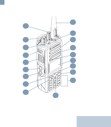
Radio Controls
Full Keypad Radio
1
2
3
4
5
6
7
8
910
11
12
13
14
15
16
17
18
19
18
English
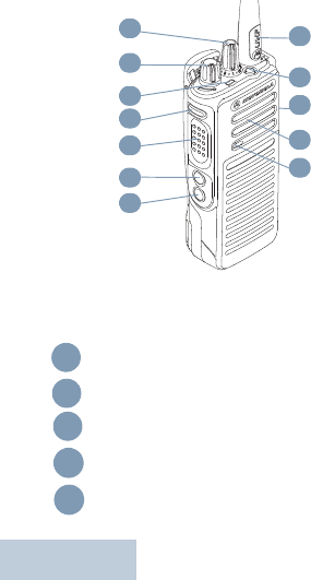
Non-Keypad Radio
Record your radio’s programmable button functions in
the blanks provided. SP represents short press, LP
represents long press.
Channel Selector Knob
On/Off/Volume Control Knob
LED Indicator
Side Button 1 (Programmable)
SP: __________ LP: ___________
Push-to-Talk (PTT) Button
1
2
3
4
5
6
7
15
16
17
18
19
1
2
3
4
5

19 English
Side Button 2 (Programmable)
SP: ____________LP: ___________
Side Button 3(Programmable)
SP: ___________ LP: ___________
Front Button P1 (Programmable)
SP: ___________ LP: ___________
Menu/OK Button
4-Way Navigation Button
Keypad
Back/Home Button
Front Button P2 (Programmable)
SP: ___________ LP: ___________
Display
Microphone
Speaker
Universal Connector for Accessories
Emergency Button (Programmable)
Antenna
6
7
8
9
10
11
12
13
14
15
16
17
18
19

20
English
Display Icons
The following are the icons that appear on the
radio’s display.
Received Signal Strength Indicator
(RSSI)
The number of bars displayed represents
the radio signal strength. Four bars indicate
the strongest signal. This icon is only
displayed while receiving.
Battery
The number of bars (0 – 4) shown indicates
the charge remaining in the battery.Blinks
when the battery is low.
Emergency
Radio is in Emergency mode.
Notification
Notification List has one or more missed
events.
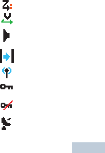
Scan*‡
Scan feature is enabled.
Scan – Priority 1*‡
Radio detects activity on channel/group
designated as Priority 1.
21 English
Scan – Priority 2 *‡
Radio detects activity on channel/group
designated as Priority 2.
Vote Scan
Vote scan feature is enabled.
Monitor
Selected channel is being monitored.
Talkaround*‡
In the absence of a repeater, radio is cur-
rently configured for direct radio to radio
communication.
Site Roaming*
The site roaming feature is enabled.
Secure
The voice privacy feature is enabled.
Unsecure
The voice privacy feature is disabled.
GPS Available
The GPS feature is enabled. The icon stays
lit when a position fix is available.

22
English
* Not applicable in Capacity Plus
‡ Not applicable in Linked Capacity Plus
Call Icons
The following icons appear during a call, and in the
Contacts list to indicate ID type.
GPS Not Available/Out of Range
The GPS feature is enabled but is not
receiving data from the satellite.
Option Board
The Option Board is enabled.
Option Board Non-Function
The Option Board is disabled.
Tones Disable
Tones are turned off.
Private Call
Indicates a Private Call in progress.
In the Contacts list, it indicates a
subscriber alias (name) or ID (number).
Group Call/All Call
Indicates a Group Call or All Call in
progress. In the Contacts list, it indicates a
group alias (name) or ID (number).
23 English
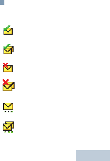
Sent Items Icons
The following icons appear at the top right corner of
the radio’s display in the Sent Items folder.
Sent Successfully
The text message is sent successfully.
Send Failed
The text message cannot be sent.
In-Progress
•The text message to a subscriber alias or
ID is pending transmission, followed by
waiting for acknowledgement.
•The text message to a group alias or ID
is pending transmission.
OR
OR
OR

24
English
LED Indicator
Blinking red – Radio is transmitting at low battery
condition, receiving an emergency transmission or
has failed the self-test upon powering up.
Solid green – Radio is powering up, or transmitting.
Also indicates full charge of the battery when Battery
Strength button is pressed.
Blinking green – Radio is receiving a non-privacy-
enabled call or data, or detecting activity over the air.
Double blinking green – Radio is receiving a
privacy-enabled call or data .
Solid yellow – Radio is monitoring a conventional
channel.
Blinking yellow – Radio is scanning for activity or
receiving a Call Alert, or all local Linked Capacity Plus
channels are busy.
Double blinking yellow – Radio is no longer
connected to the repeater while in Capacity Plus or
Linked Capacity Plus, all Capacity Plus channels or
Linked Capacity Plus channels are currently busy,
Auto Roaming is enabled, radio is actively searching
for a new site. Also indicates radio has yet to respond
to a group call alert, or radio is locked.

25 English
Charging the Battery
Your radio is powered by a Lithium-Ion (Li-lon) battery.
To avoid damage and comply with warranty terms,
charge the battery using a Motorola charger exactly
as described in the charger user guide.
If battery is attached to your radio, ensure that your
radio remains powered off while charging.
Charge a new battery 14 to 16 hours before initial use
for best performance.
IMPORTANT: ALWAYS charge your IMPRES battery
with an IMPRES charger for optimized
battery life and valuable battery data.
IMPRES batteries charged exclusively
with IMPRES chargers receive a 6-
month capacity warranty extension over
the standard Motorola Premium battery
warranty duration.
Charge your battery only in non-
hazardous areas. After battery is charged,
allow your radio to rest for at least 3
minutes.
C a u t i o n
26
English
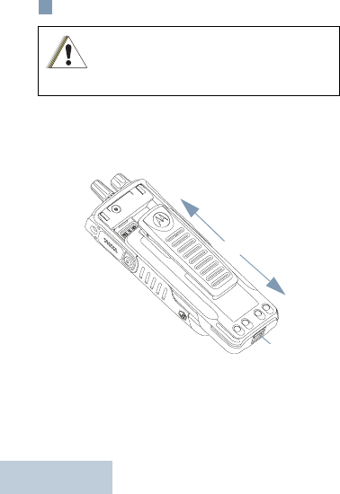
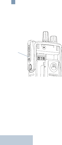
Attaching the Battery
Align the battery with the rails on the back of the radio.
Press the battery firmly, and slide upward until the
latch snaps into place. Slide battery latch into lock
position.
To remove the battery, turn the radio off. Move the
battery latch into unlock position and hold, and slide
the battery down and off the rails.
Do not replace batttery in gas and dust
environments. Replace battery only in
non-hazardous areas.
C a u t i o n
To Lock
To Unlock
Battery
Latch
27 English
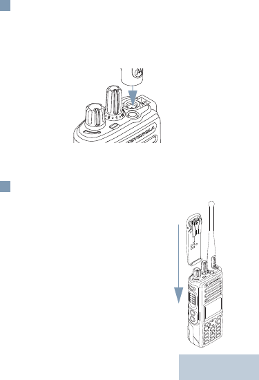
Attaching the Antenna
With the radio turned off, set the antenna in its
receptacle and turn clockwise.
Make sure that the antenna is tightened securely to
the radio.
To remove the antenna, turn the antenna
counterclockwise.
Attaching the Belt Clip
Align the grooves on the clip with
those on the battery and press
downward until you hear a click.
To remove the clip, press the belt
clip tab away from the battery.
Using a key may be helpful. Then
slide the clip upward and away from
the radio.
28
English
Attaching the Universal Connector
Cover (Dust Cover)
The universal connector is located on the antenna
side of the radio. It is used to connect MOTOTRBO
accessories to the radio.
Insert the hooked
end of the cover into
the slots above the
universal connector.
Press downward on
the cover to seat the
lower tab properly
into the RF
connector.
Turn the
thumbscrew
clockwise to secure
the connector cover to the radio.
To remove the universal connector cover, press down
on the cover and turn the thumbscrew
counterclockwise. Lift the cover up, slide the
connector cover loop upwards, and remove it from the
attached antenna.
Replace the dust cover when the universal connector
is not in use.
Dust
Cover

29 English
Powering Up the Radio
Rotate the On/Off/Volume Control Knob clockwise
until you hear a click. You see MOTOTRBO (TM) on the
radio’s display momentarily, followed by a welcome
message or welcome image.
The LED lights up solid green and the Home screen
lights up if the backlight setting is set to turn on
automatically.
If enabled, a brief tone sounds indication that the
power up test is successful.
To turn off the radio, rotate the knob clockwise until
you hear a click.
Adjusting the Volume
To increase the volume, turn the On/Off Volume
Control Knob clockwise.
To decrease the volume, turn this knob
counterclockwise.
NOTE: Your radio can be programmed to have a
minimum volume offset where the volume
level cannot be turned down fully. Check
with your dealer or system administrator for
more information.

30
English
Accessing the Radio from Password
1 Power up the radio.
2. You hear a continuous tone.
3. Enter your current four-digit password with the
radio’s keypad. The display shows ●●●●. Press
cto proceed.OR
Enter your current four-digit password. Press ^ or
v to edit each digit’s numeric value. Press > or c
to move to the next digit. Each digit changes to ●.
Press c to confirm your selection.
You hear a positive indicator tone for every digit
pressed. Press < to remove the each ● on the
display. You hear a negative indicator tone, if you
press < when the line is empty, or if you press
more than four digits.
4. If the password is correct:
Your radio proceeds to power up. See Powering
Up the Radio on page 29.
OR
If the password is incorrect:
The display shows Wrong Password. Repeat
Step 3.
OR
After the third incorrect password, the display
shows Wrong Password and then shows Radio
Locked. A tone sounds and the LED double blinks
yellow.

31 English
Selecting a Zone
Full Keypad Radio
A zone is a group of channels. The full keypad radio
supports up to 1000 channels and 250 zones, with a
maximum of 160 channels per zone.
Use the following procedure to select a zone.
Procedure:
Press the programmed Zone button and proceed to
Step 3.
OR
Follow the procedure below.
1c to access the menu.
2. ^ or v to Zone and press c to select.
3. The current zone is displayed and indicated by a
.
4. ^ or v to the required zone and proceed to Step 7.
OR
Key in the first character of the required zone.
5. A blinking cursor appears.
Use the keypad to type the required zone.
Press < to move one space to the left.
Press > to move one space to the right.
Press the *DEL key to delete any unwanted
characters.
6. The first line of the display shows the characters
you keyed in. The next lines of the display show

32
English
the shortlisted search results.
The alias search is case-insensitive. If there are
two or more zones with the same name, the radio
displays the zone that is listed first in the zone list.
7. Press c to select.
8. The display shows <Zone> Selected
momentarily and returns to the selected zone
screen.
Non-Keypad Radio
The non-keypad radio supports up to 32 channels and
2 zones, with a maximum of 16 channels per zone.
1 Press the programmed Zone button.
2. You hear a positive indicator tone, indicating the
radio has switched from Zone 1 to Zone 2.
OR
You hear a negative indicator tone, indicating the
radio has switched from Zone 2 to Zone 1.
Selecting a Channel
Once the required zone is displayed (if you have
multiple zones in your radio), turn the programmed
Channel Selector Knob to select the channel.
After selecting your channel, you can select a
subscriber alias or ID, or group alias or ID by using:
•The Channel Selector Knob

33 English
•A programmed One Touch Access button.
•The Contacts list (Applicable for Full Keypad Radio
and Limited Keypad Radio only).
•The programmed number keys – This method is for
Group, Private and All Calls only and is used with the
keypad (Applicable for Full Keypad Radio only).
•Manual Dial (via Contacts) – This method is for Pri-
vate Calls only and is dialed using a keypad micro-
phone (Applicable for Full Keypad Radio only).
NOTE: Indicated a conventional Analog
Mode-Only feature.
Indicates a conventional Digital
Mode-Only feature
Making a Group Call
1 Turn the Channel Selector Knob to select the
channel with the active group alias or ID.
2. c to access the menu.^ or v to Contacts and
pressc to select.The entries are alphabetically
sorted. ^ or v to the required group alias or ID.**
OR
^ or v to Manual Dial and press c to select. A
blinking cursor appears. Enter the group alias or
ID you want to call.**
3. Hold the radio vertically 1 to 2 inches (2.5 to 5.0
cm) from your mouth.

34
English
4. Press the PTT button to make the call. The LED
lights up solid green. The Group Call icon appears
in the top right corner. The first text line shows the
group call alias.
5. Wait for the Talk Permit Tone to finish (if enabled)
and speak clearly into the microphone.
OR
Wait for the PTT Sidetone to finish (if enabled)
and speak clearly into the microphone.
6. Release the PTT button to listen.When the target
radio responds, the LED blinks green. You see the
Group Call icon, the group alias or ID, and
transmitting radio alias or ID on your display.
7. If the Channel Free Indication feature is
enabled, you will hear a short alert tone the
moment the target radio releases the PTT button,
indicating the channel is free for you to respond.
Press the PTT button to respond.
OR
If there is no voice activity for a predetermined
period of time, the call ends.
8. Radio returns to the screen you were on prior to
initiating the call.
** not applicable for Non-Keypad Radio.

35 English
Making a Private Call
1 Turn the Channel Selector Knob to select the
channel with the active subscriber alias or ID.
2. c to access the menu.^ or v to Contacts and
pressc to select.The entries are alphabetically
sorted. ^ or v to the required group alias or ID.**
OR
^ or v to Manual Dial and press c to select. A
blinking cursor appears. Enter the group alias or
ID you want to call.**
3. Hold the radio vertically 1 to 2 inches (2.5 to 5.0
cm) from your mouth.
4. Press the PTT button to make the call. The LED
lights up solid green. The Private Call icon appears
in the top right corner. The first text line shows the
subscriber alias. The second text line displays the
call status.
5. Wait for the Talk Permit Tone to finish (if enabled)
and speak clearly into the microphone.
6. Release the PTT button to listen. When the target
radio responds, the LED blinks green.
7. If the Channel Free Indication feature is enabled,
you will hear a short alert tone the moment the
target radio releases the PTT button, indicating the
channel is free for you to respond. Press the PTT
button to respond.
OR

36
English
If there is no voice activity for a predetermined
period of time, the call ends.
8. You hear a short tone. The display shows Call
Ended.
NOTE: Indicates a conventional Digital
Mode-Only feature.
** not applicable for Non-Keypad Radio.
Making an All Call
1 Turn the Channel Selector Knob to select the
channel with the active All Call group alias or ID.
2. Hold the radio vertically 1 to 2 inches (2.5 to 5.0
cm) from your mouth.
3. Press the PTT button to make the call. The LED
lights up solid green. The Group Call icon appears
in the top right corner. The first text line shows All
Call.
4. Wait for the Talk Permit Tone to finish (if enabled)
and speak clearly into the microphone.
OR
Wait for the PTT Sidetone to finish (if enabled)
and speak clearly into the microphone.
Users on the channel cannot respond to an All Call.

37 English
Scanning Channels
NOTE: This feature is not applicable in Capacity
Plus.
Press the programmed Scan button to turn scan on or
off.
During scan, the LED blinks yellow and the scan icon
is displayed.
NOTE: Please see the User Guide for details on
Starting and Stopping Scan through the
radio menu.
Making a Call Alert
Full Keypad Radio
Press the programmed One Touch Access button
and proceed to Step 6.
OR
Follow the procedure below.
1c to access the menu.
2. ^ or v to Contacts and press c to select.
3. ^ or v to the required subscriber alias or ID and
press c to select.
OR
^ or v to Manual Dial and press c to select.
A blinking cursor appears. Enter the subscriber ID
you want to page and press c.

38
English
4. ^ or v to Call Alert and press c to select.
5. The display shows Call Alert and the subscriber
alias or ID, indicating that the Call Alert has been
sent.
6. The LED lights up solid green when your radio is
sending the Call Alert.
7. If the Call Alert acknowledgement is received, the
display shows positive mini notice.
OR
If the Call Alert acknowledgement is not received,
the display shows negative mini notice.
Non-Keypad Radio
1 Press the programmed One Touch Access button
to make a Call Alert to the predefined ID.
2. The LED lights up solid green when your radio is
sending the Call Alert.
3. If the Call Alert acknowledgement is received, two
chirps sound.
OR
If the Call Alert acknowledgement is not received,
a low-pitch tone sounds.
Sending a Quick Text Message
Full Keypad Radio

39 English
Press the programmed Text Message button and
proceed to Step 3.
OR
Press the programmed One Touch Access button to
send a predefined Quick Text message to a
predefined alias or ID and proceed to Step 6.
OR
Follow the procedure below.
1c to access the menu.
2. ^ or v to Messages and press c to select.
3. ^ or v to Quick Text and press c to select.
4. ^ or v to the required Quick Text and press c to
select.
5. A blinking cursor appears.
Use the keypad to edit the message, if required.
Press < to move one space to the left.
Press > or the # key to move one space to the
right.
Press the *DEL key to delete any unwanted
characters.
6. Press c once message is composed.
7. ^ or v to the required alias or ID and press c to
select.
OR
^ or v to Manual Dial and press c to select.
Key in the subscriber alias or ID and press c.
OR
d to edit the message.

40
English
d again to discard the message or save it to the
Drafts folder.
8. The display shows transitional mini notice,
confirming your message is being sent.
9. If the message is sent, a tone sounds and the
display shows positive mini notice.
OR
If the message is not sent, a low tone sounds and
the display shows negative mini notice.
Non-Keypad Radio
You can send Quick Text messages, programmed by
your dealer, via the programmable button.
1 Press the programmed One Touch Access button
to send a predefined Quick Text message to a
predefined ID.
2. The LED lights up solid green.
3. Two chirps indicate that the message is sent
successfully.
OR
A low-pitch tone indicates that the message
cannot be sent.
Sending an Emergency Alarm
1 Press the programmed Emergency On button.
2. The display shows Tx Alarm and the destination
alias. The LED lights up solid green and the

41 English
Emergency icon appears.
OR
The display shows Tx Telegram and the
destination alias. The LED lights up solid green
and the Emergency icon appears.
3. When an Emergency Alarm acknowledgment is
received, the Emergency tone sounds and the
LED blinks green. The display shows Alarm Sent.
OR
If your radio does not receive an Emergency Alarm
acknowledgement, and after all retries have been
exhausted, a tone sounds and the display shows
Alarm Failed.
4. Radio exits the Emergency Alarm mode and
returns to the Home screen.
If your radio is set to Silent, it will not display any
audio or visual indicators during Emergency mode.
NOTE: For more details about the above mentioned
operations, and advanced features
supported by the radios, please consult the
User Guide document:
• 68009585001 MOTOTRBO XPR 7550 Ex
Color Display Portable User Guide