Motorola Ls4208 Users Manual Symbol Product Reference Guide (p/n 72E 69413 06 Revision A)
symbol_ls4208_produc.. symbol_ls4208_product_reference
ls4208 0c21c728-213d-4051-980e-09657e8b7069 Motorola Headphones LS4208 User Guide |
2015-01-23
: Motorola Motorola-Ls4208-Users-Manual-271657 motorola-ls4208-users-manual-271657 motorola pdf
Open the PDF directly: View PDF ![]() .
.
Page Count: 360 [warning: Documents this large are best viewed by clicking the View PDF Link!]
- Symbol LS4208 Product Reference Guide
- Table of Contents
- About This Guide
- Getting Started
- Scanning
- Maintenance, Troubleshooting & Technical Specifications
- User Preferences
- Keyboard Wedge Interface
- RS-232 Interface
- USB Interface
- IBM Interface
- Wand Emulation Interface
- Scanner Emulation Interface
- 123Scan
- Symbologies
- Introduction
- Scanning Sequence Examples
- Errors While Scanning
- Symbology Parameter Defaults
- UPC/EAN
- Enable/Disable UPC-A/ UPC-E
- Enable/Disable UPC-E1
- Enable/Disable EAN-13/EAN-8
- Enable/Disable Bookland EAN
- Decode UPC/EAN/JAN Supplementals
- UPC/EAN/JAN Supplemental Redundancy
- Transmit UPC-A Check Digit
- Transmit UPC-E Check Digit
- Transmit UPC-E1 Check Digit
- UPC-A Preamble
- UPC-E Preamble
- UPC-E1 Preamble
- Convert UPC-E to UPC-A
- Convert UPC-E1 to UPC-A
- EAN-8/JAN-8 Extend
- Bookland ISBN Format
- UCC Coupon Extended Code
- Code 128
- Code 39
- Code 93
- Code 11
- Interleaved 2 of 5 (ITF)
- Discrete 2 of 5 (DTF)
- Chinese 2 of 5
- Codabar (NW - 7)
- MSI
- GS1 DataBar (formerly RSS - Reduced Space Symbology)
- PDF417/MicroPDF417
- Composite Codes
- Symbology - Specific Security Levels
- Intercharacter Gap
- Miscellaneous Scanner Options
- Advanced Data Formatting
- Standard Default Parameters
- Programming References
- Sample Bar Codes
- Numeric Bar Codes
- ASCII Character Sets
- Index
- Tell Us What You Think...
Symbol LS4208
Product Reference Guide

Symbol LS4208
Product Reference Guide
72E-69413-06
Revision A
April 2009

ii Symbol LS4208 Product Reference Guide
© 2009 by Motorola, Inc. All rights reserved.
No part of this publication may be reproduced or used in any form, or by any electrical or mechanical means,
without permission in writing from Motorola. This includes electronic or mechanical means, such as
photocopying, recording, or information storage and retrieval systems. The material in this manual is subject to
change without notice.
The software is provided strictly on an “as is” basis. All software, including firmware, furnished to the user is on
a licensed basis. Motorola grants to the user a non-transferable and non-exclusive license to use each
software or firmware program delivered hereunder (licensed program). Except as noted below, such license
may not be assigned, sublicensed, or otherwise transferred by the user without prior written consent of
Motorola. No right to copy a licensed program in whole or in part is granted, except as permitted under
copyright law. The user shall not modify, merge, or incorporate any form or portion of a licensed program with
other program material, create a derivative work from a licensed program, or use a licensed program in a
network without written permission from Motorola. The user agrees to maintain Motorola’s copyright notice on
the licensed programs delivered hereunder, and to include the same on any authorized copies it makes, in
whole or in part. The user agrees not to decompile, disassemble, decode, or reverse engineer any licensed
program delivered to the user or any portion thereof.
Motorola reserves the right to make changes to any software or product to improve reliability, function, or
design.
Motorola does not assume any product liability arising out of, or in connection with, the application or use of
any product, circuit, or application described herein.
No license is granted, either expressly or by implication, estoppel, or otherwise under any Motorola, Inc.,
intellectual property rights. An implied license only exists for equipment, circuits, and subsystems contained in
Motorola products.
MOTOROLA and the Stylized M Logo and Symbol and the Symbol logo are registered in the US Patent &
Trademark Office. Bluetooth is a registered trademark of Bluetooth SIG. Microsoft, Windows and ActiveSync
are either registered trademarks or trademarks of Microsoft Corporation. All other product or service names
are the property of their respective owners.
Motorola, Inc.
One Motorola Plaza
Holtsville, New York 11742-1300
http://www.motorola.com/enterprisemobility
Patents
This product is covered by one or more of the patents listed on the website:
http://www.motorola.com/enterprisemobility/patents.
Warranty
For the complete Motorola hardware product warranty statement, go to:
http://www.motorola.com/enterprisemobility/warranty.

iii
Revision History
Changes to the original manual are listed below:
Change Date Description
-01 Rev A 5/2005 Initial release.
-02 Rev A 6/2005 Update RSS description.
-03 Rev A 1/2007 Update service section, add special IBM command bar codes, add parameter bar
codes for Bookland ISBN format and new UPC supplemental decode options, add
bar codes for report version, report MIMIC version, and report Synapse cable, add
ADF section.
-04 Rev A 6/2007 Add information for LS4208PR version, which supports PDF417.
-05 Rev A 7/2007 Add note to end of Wand Emulation chapter regarding error beep emitted when
scanner attempts to send composite data.
-06 Rev A 4/2009 Add Parameter Scanning option, add Simple COM Port Emulation to USB device
type parameter, add new ADF options.

iv Symbol LS4208 Product Reference Guide

Table of Contents
About This Guide
Introduction.................................................................................................................... xiii
Notational Conventions.................................................................................................. xiv
Related Documents ....................................................................................................... xiv
Service Information........................................................................................................ xv
Chapter 1: Getting Started
Introduction ................................................................................................................... 1-1
Unpacking ..................................................................................................................... 1-2
Setting Up the Scanner ................................................................................................. 1-3
Installing the Interface Cable .................................................................................. 1-3
Removing the Interface Cable ................................................................................ 1-4
Connecting a Synapse Cable Interface .................................................................. 1-4
Connecting Power (if required) ............................................................................... 1-4
Configuring the Scanner ......................................................................................... 1-5
Chapter 2: Scanning
Introduction ................................................................................................................... 2-1
Beeper Definitions ........................................................................................................ 2-2
LED Definitions ............................................................................................................. 2-3
Scan Patterns ............................................................................................................... 2-4
Single-Line Only ...................................................................................................... 2-4
Multi-Line Smart Raster .......................................................................................... 2-4
Multi-line Always Raster .......................................................................................... 2-4
Scanning Modes ........................................................................................................... 2-5
Scanning in Hand-Held Mode ................................................................................. 2-5
Scanning in Hands-Free Mode ............................................................................... 2-9
Symbol LS4208 Decode Zone ...................................................................................... 2-11

vi Symbol LS4208 Product Reference Guide
Chapter 3: Maintenance, Troubleshooting & Technical Specifications
Introduction ................................................................................................................... 3-1
Maintenance ................................................................................................................. 3-1
Troubleshooting ............................................................................................................ 3-2
Technical Specifications ............................................................................................... 3-5
Scanner Signal Descriptions ......................................................................................... 3-7
Chapter 4: User Preferences
Introduction ................................................................................................................... 4-1
Scanning Sequence Examples ..................................................................................... 4-1
Errors While Scanning .................................................................................................. 4-1
User Preferences Parameter Defaults .......................................................................... 4-2
User Preferences .......................................................................................................... 4-3
Default Parameters ................................................................................................. 4-3
Parameter Bar Code Scanning ............................................................................... 4-4
Beeper Tone ........................................................................................................... 4-4
Beeper Volume ....................................................................................................... 4-5
Power Mode ............................................................................................................ 4-5
Scan Pattern ........................................................................................................... 4-6
Scan Line Width ...................................................................................................... 4-7
Raster Height .......................................................................................................... 4-8
Laser On Time ........................................................................................................ 4-9
Beep After Good Decode ........................................................................................ 4-9
PDF Decode Feedback ........................................................................................... 4-10
Chapter 5: Keyboard Wedge Interface
Introduction ................................................................................................................... 5-1
Connecting a Keyboard Wedge Interface ..................................................................... 5-2
Keyboard Wedge Parameter Defaults .......................................................................... 5-3
Keyboard Wedge Host Parameters .............................................................................. 5-4
Keyboard Wedge Host Types ................................................................................. 5-4
Keyboard Wedge Country Types (Country Codes) ................................................ 5-5
Ignore Unknown Characters ................................................................................... 5-6
Keystroke Delay ...................................................................................................... 5-7
Intra-Keystroke Delay ............................................................................................. 5-7
Alternate Numeric Keypad Emulation ..................................................................... 5-8
Caps Lock On ......................................................................................................... 5-8
Caps Lock Override ................................................................................................ 5-9
Convert Wedge Data .............................................................................................. 5-10
Function Key Mapping ............................................................................................ 5-10
FN1 Substitution ..................................................................................................... 5-11
Send Make and Break ............................................................................................ 5-11
Keyboard Maps ....................................................................................................... 5-12
ASCII Character Set for Keyboard Wedge ................................................................... 5-13

Table of Contents vii
Chapter 6: RS-232 Interface
Introduction ................................................................................................................... 6-1
Connecting an RS-232 Interface .................................................................................. 6-2
RS-232 Parameter Defaults .......................................................................................... 6-3
RS-232 Host Parameters .............................................................................................. 6-4
RS-232 Host Types ................................................................................................. 6-6
Baud Rate ............................................................................................................... 6-7
Parity ....................................................................................................................... 6-8
Stop Bit Select ........................................................................................................ 6-9
Data Bits (ASCII Format) ........................................................................................ 6-9
Check Receive Errors ............................................................................................. 6-10
Hardware Handshaking .......................................................................................... 6-10
Software Handshaking ............................................................................................ 6-12
Host Serial Response Time-out .............................................................................. 6-14
RTS Line State ........................................................................................................ 6-15
Beep on <BEL> ....................................................................................................... 6-15
Intercharacter Delay ................................................................................................ 6-16
Nixdorf Beep/LED Options ...................................................................................... 6-17
Ignore Unknown Characters ................................................................................... 6-17
ASCII Character Set for RS-232 ................................................................................... 6-18
Chapter 7: USB Interface
Introduction ................................................................................................................... 7-1
Connecting a USB Interface ......................................................................................... 7-2
USB Parameter Defaults .............................................................................................. 7-4
USB Host Parameters .................................................................................................. 7-5
USB Device Type .................................................................................................... 7-5
USB Country Keyboard Types (Country Codes) .................................................... 7-6
USB Keystroke Delay ............................................................................................. 7-8
USB CAPS Lock Override ...................................................................................... 7-8
USB Ignore Unknown Characters ........................................................................... 7-9
Emulate Keypad ...................................................................................................... 7-9
USB Keyboard FN 1 Substitution ............................................................................ 7-10
Function Key Mapping ............................................................................................ 7-10
Simulated Caps Lock .............................................................................................. 7-11
Convert Case .......................................................................................................... 7-11
ASCII Character Set for USB ........................................................................................ 7-12
Chapter 8: IBM Interface
Introduction ................................................................................................................... 8-1
Connecting to an IBM 468X/469X Host ........................................................................ 8-2
IBM Parameter Defaults ............................................................................................... 8-3
IBM 468X/469X Host Parameters ................................................................................. 8-4
Port Address ........................................................................................................... 8-4
Convert Unknown to Code 39 ................................................................................. 8-5
Optional IBM Parameters ............................................................................................. 8-6
Ignore Beep ............................................................................................................ 8-6
Ignore Bar Code Configuration ............................................................................... 8-6

viii Symbol LS4208 Product Reference Guide
Chapter 9: Wand Emulation Interface
Introduction ................................................................................................................... 9-1
Connecting Using Wand Emulation .............................................................................. 9-2
Wand Emulation Parameter Defaults ........................................................................... 9-3
Wand Emulation Host Parameters ............................................................................... 9-4
Wand Emulation Host Types .................................................................................. 9-4
Leading Margin (Quiet Zone) .................................................................................. 9-5
Polarity .................................................................................................................... 9-6
Ignore Unknown Characters ................................................................................... 9-6
Convert All Bar Codes to Code 39 .......................................................................... 9-7
Convert Code 39 to Full ASCII ............................................................................... 9-8
Chapter 10: Scanner Emulation Interface
Introduction ................................................................................................................... 10-1
Connecting Using Scanner Emulation .......................................................................... 10-2
Scanner Emulation Parameter Defaults ....................................................................... 10-3
Scanner Emulation Host ............................................................................................... 10-4
Scanner Emulation Host Parameters ........................................................................... 10-4
Beep Style ............................................................................................................... 10-4
Parameter Pass-Through ........................................................................................ 10-5
Convert Newer Code Types .................................................................................... 10-6
Module Width .......................................................................................................... 10-7
Convert All Bar Codes to Code 39 .......................................................................... 10-7
Code 39 Full ASCII Conversion .............................................................................. 10-8
Transmission Timeout ............................................................................................. 10-9
Ignore Unknown Characters ................................................................................... 10-10
Leading Margin ....................................................................................................... 10-10
Check For Decode LED .......................................................................................... 10-11
Chapter 11: 123Scan
Introduction ................................................................................................................... 11-1
Communication with 123Scan ...................................................................................... 11-1
123Scan Parameter ...................................................................................................... 11-1
Chapter 12: Symbologies
Introduction ................................................................................................................... 12-1
Scanning Sequence Examples ..................................................................................... 12-1
Errors While Scanning .................................................................................................. 12-2
Symbology Parameter Defaults .................................................................................... 12-2
UPC/EAN ...................................................................................................................... 12-6
Enable/Disable UPC-A/UPC-E ............................................................................... 12-6
Enable/Disable UPC-E1 .......................................................................................... 12-7
Enable/Disable EAN-13/EAN-8 ............................................................................... 12-8
Enable/Disable Bookland EAN ............................................................................... 12-9
Decode UPC/EAN/JAN Supplementals .................................................................. 12-9
UPC/EAN/JAN Supplemental Redundancy ............................................................ 12-14
Transmit UPC-A Check Digit .................................................................................. 12-14

Table of Contents ix
Transmit UPC-E Check Digit .................................................................................. 12-15
Transmit UPC-E1 Check Digit ................................................................................ 12-15
UPC-A Preamble .................................................................................................... 12-16
UPC-E Preamble .................................................................................................... 12-17
UPC-E1 Preamble .................................................................................................. 12-18
Convert UPC-E to UPC-A ....................................................................................... 12-19
Convert UPC-E1 to UPC-A ..................................................................................... 12-19
EAN-8/JAN-8 Extend .............................................................................................. 12-20
Bookland ISBN Format ........................................................................................... 12-21
UCC Coupon Extended Code ................................................................................. 12-22
Code 128 ...................................................................................................................... 12-23
Enable/Disable Code 128 ....................................................................................... 12-23
Enable/Disable GS1-128 ........................................................................................ 12-23
Enable/Disable ISBT 128 ........................................................................................ 12-24
Code 39 ........................................................................................................................ 12-25
Enable/Disable Code 39 ......................................................................................... 12-25
Enable/Disable Trioptic Code 39 ............................................................................ 12-25
Convert Code 39 to Code 32 .................................................................................. 12-26
Code 32 Prefix ........................................................................................................ 12-26
Set Lengths for Code 39 ......................................................................................... 12-27
Code 39 Check Digit Verification ............................................................................ 12-28
Transmit Code 39 Check Digit ................................................................................ 12-29
Code 39 Full ASCII Conversion .............................................................................. 12-30
Code 39 Buffering (Scan & Store) .......................................................................... 12-31
Code 93 ........................................................................................................................ 12-34
Enable/Disable Code 93 ......................................................................................... 12-34
Set Lengths for Code 93 ......................................................................................... 12-34
Code 11 ........................................................................................................................ 12-36
Code 11 .................................................................................................................. 12-36
Set Lengths for Code 11 ......................................................................................... 12-36
Code 11 Check Digit Verification ............................................................................ 12-38
Transmit Code 11 Check Digits .............................................................................. 12-39
Interleaved 2 of 5 (ITF) ................................................................................................. 12-40
Enable/Disable Interleaved 2 of 5 ........................................................................... 12-40
Set Lengths for Interleaved 2 of 5 ........................................................................... 12-40
I 2 of 5 Check Digit Verification ............................................................................... 12-42
Transmit I 2 of 5 Check Digit ................................................................................... 12-43
Convert I 2 of 5 to EAN-13 ...................................................................................... 12-43
Discrete 2 of 5 (DTF) .................................................................................................... 12-44
Enable/Disable Discrete 2 of 5 ................................................................................ 12-44
Set Lengths for Discrete 2 of 5 ............................................................................... 12-44
Chinese 2 of 5 ............................................................................................................... 12-46
Enable/Disable Chinese 2 of 5 ................................................................................ 12-46
Codabar (NW - 7) ......................................................................................................... 12-47
Enable/Disable Codabar ......................................................................................... 12-47
Set Lengths for Codabar ......................................................................................... 12-47
CLSI Editing ............................................................................................................ 12-49
NOTIS Editing ......................................................................................................... 12-49
MSI ............................................................................................................................... 12-50
Enable/Disable MSI ................................................................................................ 12-50

x Symbol LS4208 Product Reference Guide
Set Lengths for MSI ................................................................................................ 12-50
MSI Check Digits .................................................................................................... 12-51
Transmit MSI Check Digit(s) ................................................................................... 12-52
MSI Check Digit Algorithm ...................................................................................... 12-52
GS1 DataBar (formerly RSS - Reduced Space Symbology) ........................................ 12-53
Convert GS1 DataBar to UPC/EAN ........................................................................ 12-54
PDF417/MicroPDF417 .................................................................................................. 12-55
Enable/Disable PDF417 .......................................................................................... 12-55
Enable/Disable MicroPDF417 ................................................................................. 12-55
MicroPDF Performance .......................................................................................... 12-56
Transmit Symbols in Codeword Format .................................................................. 12-57
Transmit Unknown Codewords ............................................................................... 12-58
Escape Characters ................................................................................................. 12-58
Delete Character Set ECIs ...................................................................................... 12-59
Composite Codes ......................................................................................................... 12-60
Composite CC-C ..................................................................................................... 12-60
Composite CC-A/B .................................................................................................. 12-60
UPC Composite Mode ............................................................................................ 12-61
Composite Beep Mode ........................................................................................... 12-62
Symbology - Specific Security Levels ........................................................................... 12-63
Redundancy Level .................................................................................................. 12-63
Security Level ......................................................................................................... 12-65
Bi-directional Redunda\ncy ..................................................................................... 12-66
Intercharacter Gap ........................................................................................................ 12-66
Chapter 13: Miscellaneous Scanner Options
Introduction ................................................................................................................... 13-1
Scanning Sequence Examples ..................................................................................... 13-1
Errors While Scanning .................................................................................................. 13-1
Miscellaneous Parameter Defaults ............................................................................... 13-2
Miscellaneous Scanner Parameters ............................................................................. 13-3
Transmit Code ID Character ................................................................................... 13-3
Prefix/Suffix Values ................................................................................................. 13-3
Scan Data Transmission Format ............................................................................ 13-4
FN1 Substitution Values ......................................................................................... 13-6
Transmit “No Read” Message ................................................................................. 13-6
Synapse Interface ................................................................................................... 13-7
Report Version ........................................................................................................ 13-8
Report Synapse Cable ............................................................................................ 13-8
Chapter 14: Advanced Data Formatting
Introduction ................................................................................................................... 14-1
Rules: Criteria Linked to Actions ................................................................................... 14-1
Using ADF Bar Codes .................................................................................................. 14-2
ADF Bar Code Menu Example ..................................................................................... 14-2
Rule 1: The Code 128 Scanning Rule .................................................................... 14-3
Rule 2: The UPC Scanning Rule ............................................................................ 14-3
Alternate Rule Sets ................................................................................................. 14-3

Table of Contents xi
Rules Hierarchy (in Bar Codes) .............................................................................. 14-4
Default Rules .......................................................................................................... 14-5
ADF Bar Codes ............................................................................................................. 14-5
Special Commands ....................................................................................................... 14-8
Pause Duration ....................................................................................................... 14-8
Begin New Rule ...................................................................................................... 14-8
Save Rule ............................................................................................................... 14-8
Erase ....................................................................................................................... 14-9
Quit Entering Rules ................................................................................................. 14-9
Disable Rule Set ..................................................................................................... 14-10
Criteria .......................................................................................................................... 14-11
Code Types ............................................................................................................. 14-11
Code Lengths .......................................................................................................... 14-15
Message Containing A Specific Data String ........................................................... 14-19
Actions .......................................................................................................................... 14-23
Send Data ............................................................................................................... 14-23
Setup Field(s) .......................................................................................................... 14-26
Modify Data ............................................................................................................. 14-33
Pad Data with Spaces ............................................................................................. 14-34
Pad Data with Zeros ............................................................................................... 14-38
Beeps ...................................................................................................................... 14-42
Send Keystroke (Control Characters and Keyboard Characters) ........................... 14-43
Send Right Control Key .......................................................................................... 14-75
Send Graphic User Interface (GUI) Characters ...................................................... 14-76
Turn On/Off Rule Sets ............................................................................................ 14-82
Alphanumeric Keyboard ............................................................................................... 14-83
Appendix A: Standard Default Parameters
Default Parameters ....................................................................................................... A-1
Appendix B: Programming References
Symbol Code Identifiers ................................................................................................ B-1
AIM Code Identifiers ..................................................................................................... B-2
Appendix C: Sample Bar Codes
Code 39 ........................................................................................................................ C-1
UPC/EAN ...................................................................................................................... C-1
UPC-A, 100% .......................................................................................................... C-1
EAN-13, 100% ........................................................................................................ C-2
Code 128 ...................................................................................................................... C-2
Interleaved 2 of 5 .......................................................................................................... C-2
GS1 DataBar ................................................................................................................ C-3
GS1 DataBar ........................................................................................................... C-3
GS1 DataBar-14 ..................................................................................................... C-4

xii Symbol LS4208 Product Reference Guide
Appendix D: Numeric Bar Codes
Numeric Bar Codes ...................................................................................................... D-1
Cancel ........................................................................................................................... D-3
Appendix E: ASCII Character Sets
Index
Tell Us What You Think...

About This Guide
Introduction
The Symbol LS4208 Product Reference Guide provides general instructions for setting up, operating, maintaining,
and troubleshooting the Symbol LS4208 scanner. The scanner includes the following variations of the scanner:
•
Symbol LS4208-SR: Standard version
•
Symbol LS4208-PR: PDF417 version
Chapter Descriptions
•
Chapter 1, Getting Started provides a product overview, unpacking instructions, and cable connection
information.
•
Chapter 2, Scanning describes parts of the scanner, beeper and LED definitions, and how to use the scanner
in hand-held and hands-free modes.
•
Chapter 3, Maintenance, Troubleshooting & Technical Specifications provides information on how to care for
the scanner, troubleshooting, and technical specifications.
•
Chapter 4, User Preferences provides programming bar codes for selecting user preference features for the
scanner.
•
Chapter 5, Keyboard Wedge Interface provides information for setting up the scanner for Keyboard Wedge
operation.
•
Chapter 6, RS-232 Interface provides information for setting up the scanner for RS-232 operation.
•
Chapter 7, USB Interface provides information for setting up the scanner for USB operation.
•
Chapter 8, IBM Interface provides all information for setting up the scanner with IBM 468X/469X POS
systems.
•
Chapter 9, Wand Emulation Interface provides all information for setting up the scanner for Wand Emulation
operation.
•
Chapter 10, Scanner Emulation Interface provides information for setting up the scanner for Scanner
Emulation operation.
•
Chapter 11, 123Scan (PC based scanner configuration tool) provides the bar code that must be scanned to
communicate with the 123Scan program.

xiv Symbol LS4208 Product Reference Guide
•
Chapter 12, Symbologies describes all symbology features and provides the programming bar codes
necessary for selecting these features for the scanner.
•
Chapter 13, Miscellaneous Scanner Options includes commonly used bar codes to customize how the data
is transmitted to the host device.
•
Chapter 14, Advanced Data Formatting details Advanced Data Formatting (ADF), a means of customizing
data before transmission to a host device.
•
Appendix A, Standard Default Parameters provides a table of all host devices and miscellaneous scanner
defaults.
•
Appendix B, Programming References provides a table of AIM code identifiers, ASCII character conversions,
and keyboard maps.
•
Appendix C, Sample Bar Codes includes sample bar codes.
•
Appendix D, Numeric Bar Codes includes the numeric bar codes to scan for parameters requiring specific
numeric values.
•
Appendix E, ASCII Character Sets provides ASCII character value tables.
Notational Conventions
The following conventions are used in this document:
•
Bullets indicate:
•action items
•lists of alternatives
•lists of required steps that are not necessarily sequential
•
Sequential lists (e.g., those that describe step-by-step procedures) appear as numbered lists.
•
Throughout the programming bar code menus, asterisks (*) are used to denote default parameter settings.
Related Documents
The following documents provide more information for the Symbol LS4208 scanner:
•
The Symbol LS4208 Quick Reference Guide (p/n 72-69411-xx) provides general information to help the user
get started with the scanner. It includes basic operation instructions and start up bar codes.
For the latest version of this guide and all Symbol guides, go to:
http://www.motorola.com/enterprisemobility/manuals.
*Baud Rate 9600 Feature/Option
* Indicates Default

About This Guide xv
Service Information
If you have a problem with your equipment, contact Motorola Enterprise Mobility support for your region. Contact
information is available at: http://www.motorola.com/enterprisemobility/contactsupport.
When contacting Enterprise Mobility support, please have the following information available:
•
Serial number of the unit
•
Model number or product name
•
Software type and version number
Motorola responds to calls by e-mail, telephone or fax within the time limits set forth in service agreements.
If your problem cannot be solved by Motorola Enterprise Mobility Support, you may need to return your equipment
for servicing and will be given specific directions. Motorola is not responsible for any damages incurred during
shipment if the approved shipping container is not used. Shipping the units improperly can possibly void the
warranty.
If you purchased your Enterprise Mobility business product from a Motorola business partner, please contact that
business partner for support.

xvi Symbol LS4208 Product Reference Guide
Chapter 1 Getting Started
Introduction
The scanner combines excellent scanning performance and advanced ergonomics to provide the best value in a
lightweight laser scanner. Whether used as a hand-held scanner or in hands-free mode in a stand, the scanner
ensures comfort and ease of use for extended periods of time.
In addition to single-line laser scanning, the scanner supports multi-line rastering. Multi-line rastering allows the
scanner to capture stacked GS1 DataBar codes (formerly Reduced Space Symbology/RSS) and increases angular
tolerances, minimizing product orientation and hand movements. Multi-line rastering also allows the scanner to
read poor quality bar codes. For more information about scanning modes and stacked GS1 DataBar codes, see
Scan Pattern on page 4-6 and GS1 DataBar on page C-3.
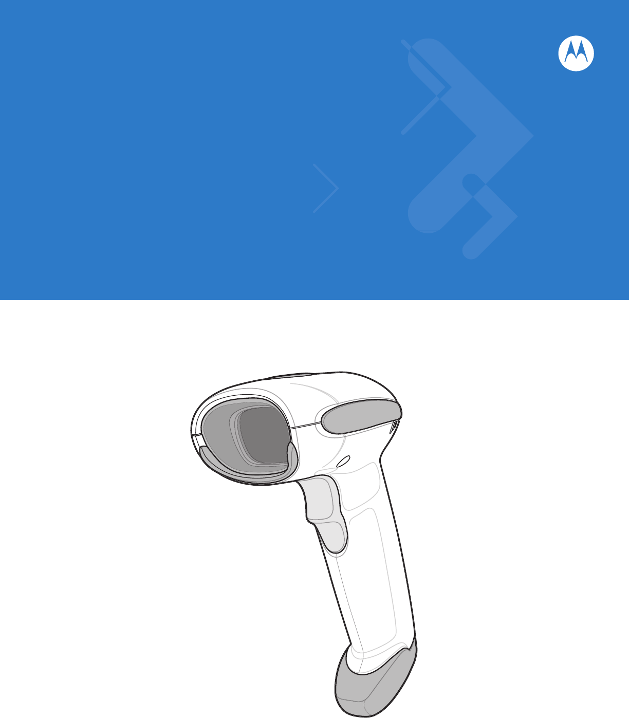
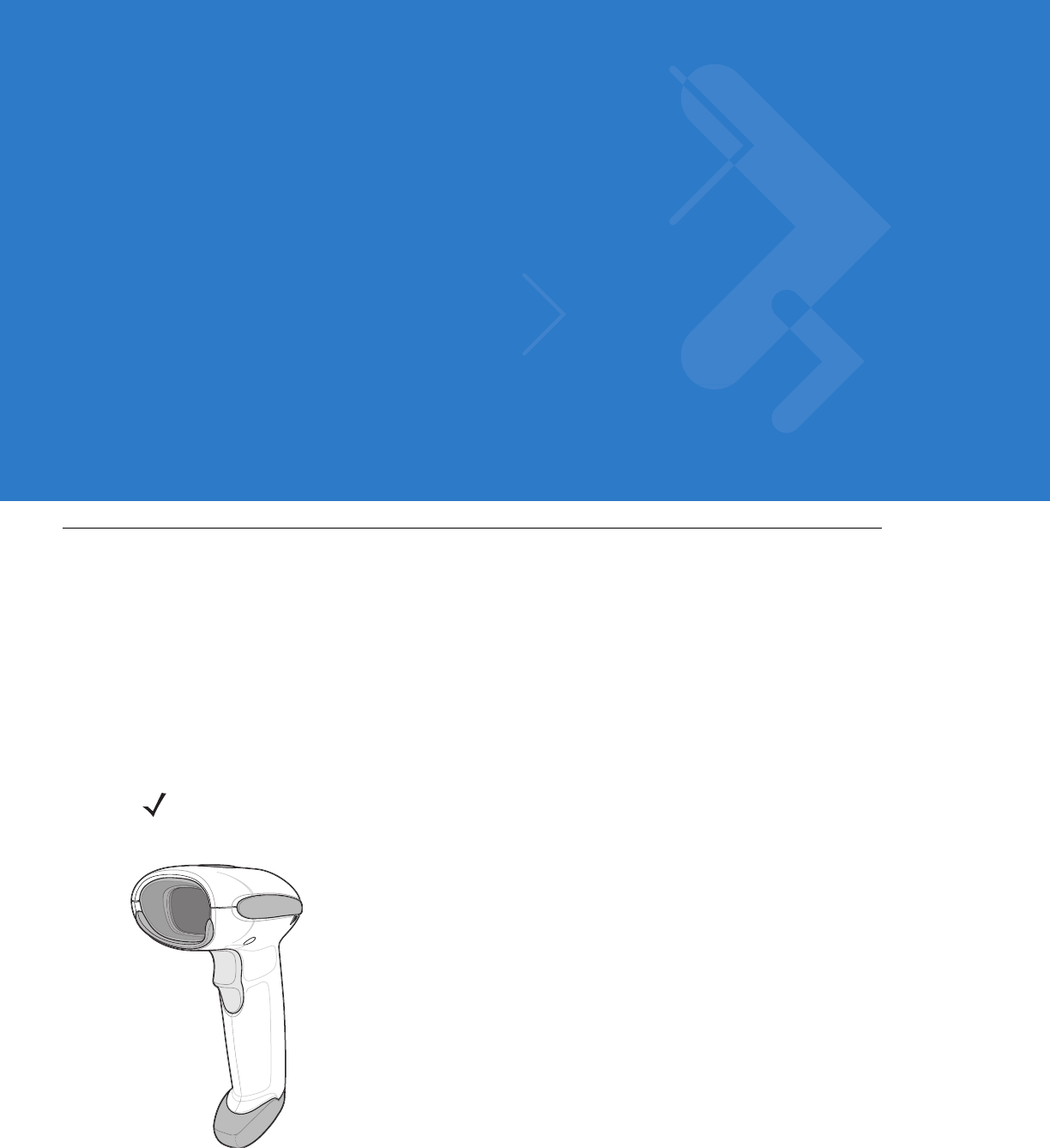
Figure 1-1
Symbol LS4208 Scanner
NOTE Only the Symbol LS4208-PR version supports PDF417 bar codes and variants.

1 - 2 Symbol LS4208 Product Reference Guide
This scanner supports the following interfaces:
•
Keyboard Wedge connection to a host. The host interprets scanned data as keystrokes. This interface
supports the following international keyboards (for Windows® environment): North America, German,
French, French Canadian, Spanish, Italian, Swedish, UK English, Portuguese-Brazilian, and Japanese.
•
Standard RS-232 connection to a host. Scan bar code menus to set up proper communication of the scanner
with the host.
•
USB connection to a host. The scanner autodetects a USB host and defaults to the HID keyboard interface
type. Select other USB interface types by scanning programming bar code menus.This interface supports the
following international keyboards (for Windows® environment): North America, German, French, French
Canadian, Spanish, Italian, Swedish, UK English, Portuguese-Brazilian, and Japanese.
•
Connection to IBM® 468X/469X hosts. Scan bar code menus to set up communication of the scanner with
the IBM terminal.
•
Wand Emulation connection to a host. The scanner is connected to a portable data terminal, a controller, or
host which collects the data as wand data and decodes it.
•
Scanner Emulation connection to a host. The scanner is connected to a portable data terminal, a controller
which collects the data and interprets it for the host.
•
Synapse capability which allows connection to a wide variety of host systems using a Synapse and Synapse
adapter cable. The scanner autodetects the host.
•
Configuration via 123Scan.
Unpacking
Remove the scanner from its packing and inspect it for damage. If the scanner was damaged in transit, contact
Motorola Enterprise Mobility Support. See page xv for contact information. KEEP THE PACKING. It is the
approved shipping container and should be used if the equipment ever needs to be return for servicing.
Getting Started 1 - 3
Setting Up the Scanner
Installing the Interface Cable
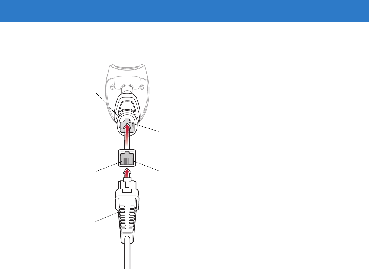
To connect the interface cable:
1. Insert the interface cable’s modular connector clip into the cable interface port on the bottom of the scanner
handle. (See Figure 1-2.).
2. Gently tug the cable to ensure the connector is properly secured.
3. Connect the other end of the interface cable to the host. (See the specific host chapter for information on host
connections.)
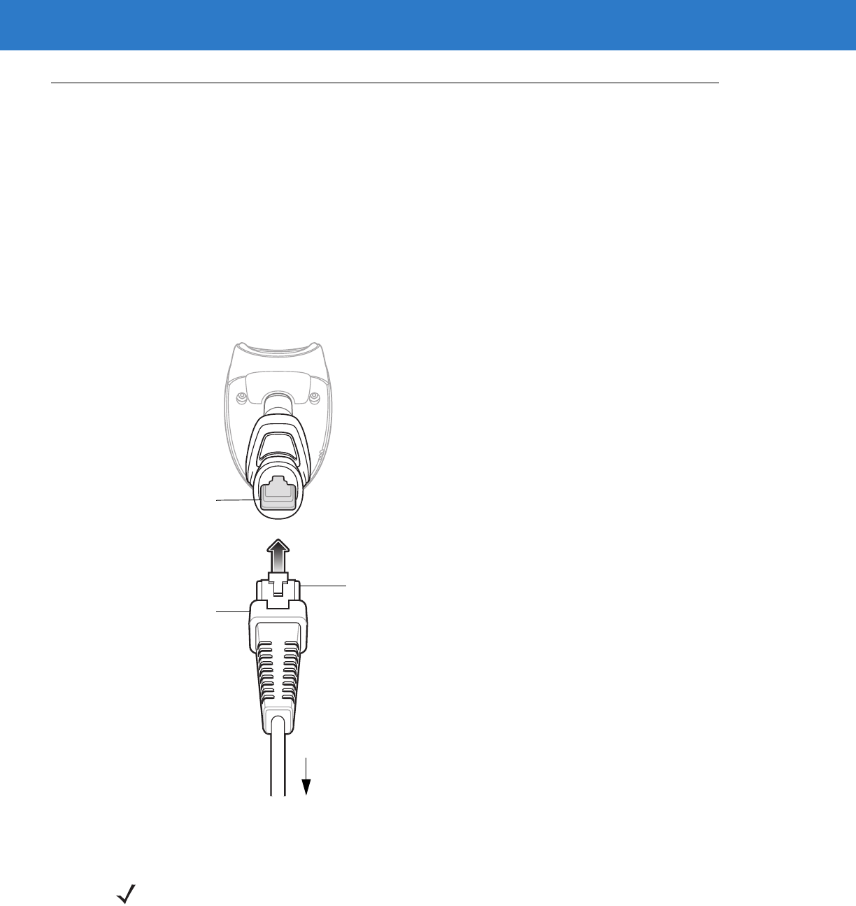
Figure 1-2
Installing the Cable
Interface cable
modular connector
To host
Cable interface
port
Interface cable modular
connector clip
NOTE Different hosts require different cables. The connectors illustrated in each host chapter are examples only.
Actual connectors may be different than those illustrated, but the steps to connect the scanner are the
same.
1 - 4 Symbol LS4208 Product Reference Guide
Removing the Interface Cable
To remove the interface cable:
1. Unplug the installed cable’s modular connector by depressing the connector clip with the tip of a screwdriver.
2. Carefully slide out the cable.
3. Follow the steps for Installing the Interface Cable on page 1-3 to connect a new cable.
Connecting a Synapse Cable Interface
Symbol’s Synapse Smart Cables enable interfacing to a variety of hosts. The appropriate Synapse cable has the
built-in intelligence to detect the host to which it is connected.
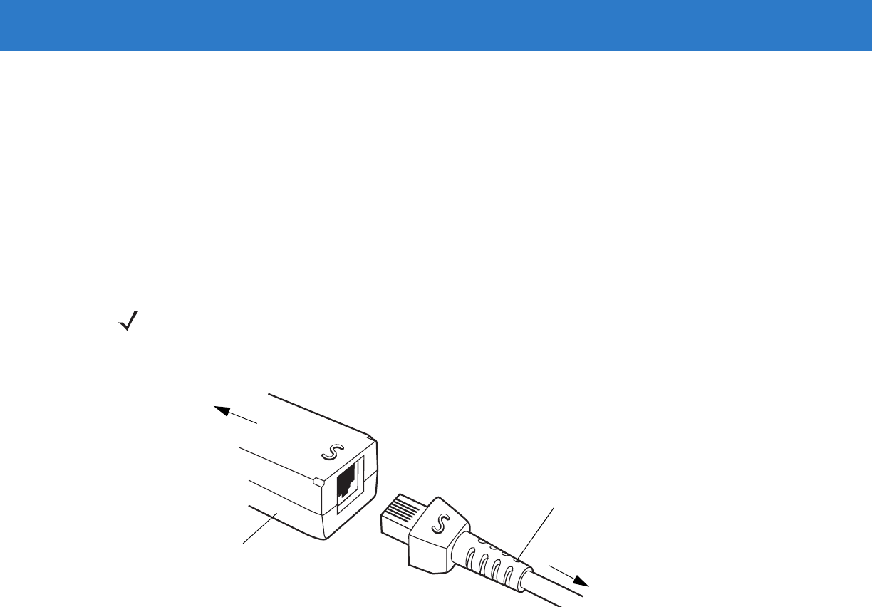
Figure 1-3
Synapse Cable Connection
1. Plug the Synapse adapter cable (p/n 25-32463-xx) into the bottom of the scanner, as described in Installing the
Interface Cable on page 1-3.
2. Align the ‘S’ on the Synapse adapter cable with the ‘S’ on the Synapse Smart Cable and plug the cable in.
3. Connect the other end of the Synapse Smart Cable to the host.
Connecting Power (if required)
If the host does not provide power to the scanner, an external power connection to the scanner is required. To
connect power:
1. Connect the interface cable to the bottom of the scanner, as described in Installing the Interface Cable on page
1-3.
2. Connect the other end of the interface cable to the host (refer to the host manual to locate the correct port).
3. Plug the power supply into the power jack on the interface cable. Plug the other end of the power supply into
an AC outlet.
NOTE Refer to the Synapse Interface Guide provided with the Synapse cable for detailed setup instructions.
Synapse Adapter Cable
To Scanner
Synapse Smart Cable
To host

Getting Started 1 - 5
Configuring the Scanner
To configure the scanner, use the bar codes included in this manual, or the 123Scan configuration program.
See Chapter 4, User Preferences, Chapter 12, Symbologies and Chapter 13, Miscellaneous Scanner Options for
information about programming the scanner using bar code menus. Also see each host-specific chapter to set up a
connection to a specific host type.
See Chapter 11, 123Scan to configure the scanner using this configuration program. A help file is available in the
program.

1 - 6 Symbol LS4208 Product Reference Guide

Chapter 2 Scanning
Introduction
This chapter provides beeper and LED definitions, techniques involved in scanning bar codes, general instructions
and tips about scanning, and decode zone diagram.
Figure 2-1
Parts
Beeper
LED
Trigger
Scan
Window
2 - 2 Symbol LS4208 Product Reference Guide
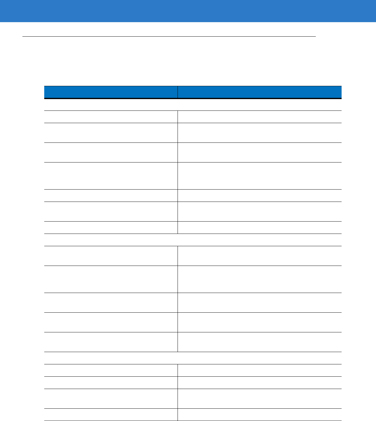
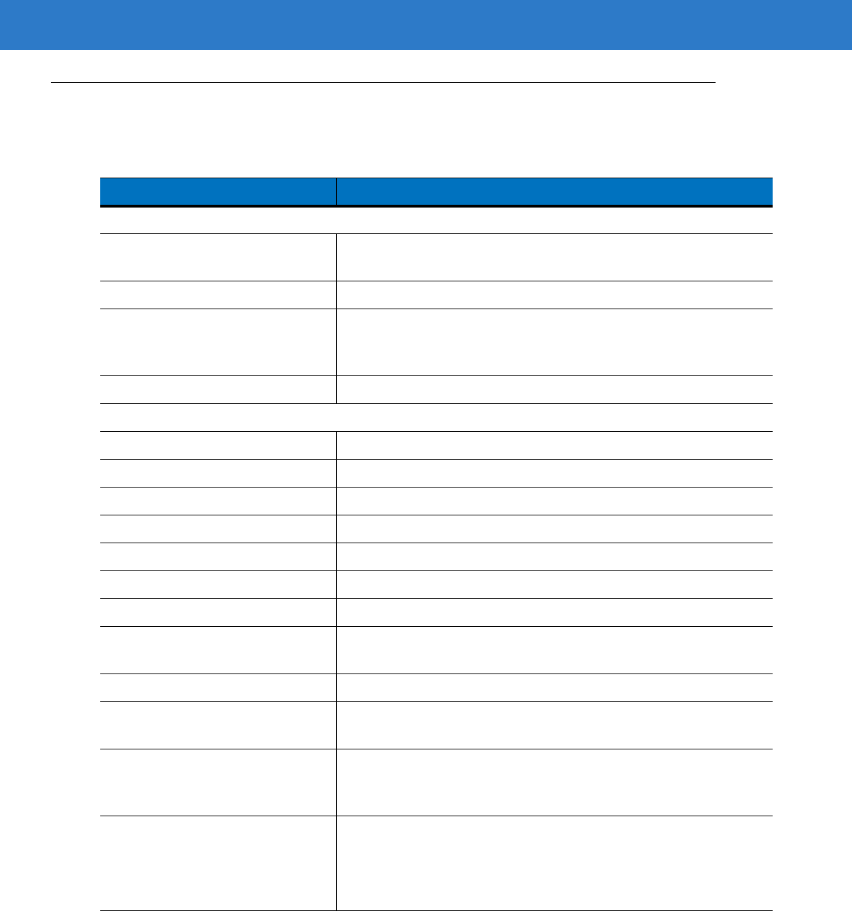
Beeper Definitions
The scanner issues different beep sequences and patterns to indicate status. Table 2-1 defines beep sequences
that occur during both normal scanning and while programming the scanner.
Table 2-1
Beeper Definitions
Beeper Sequence Indication
Standard Use
Low/medium/high beeps Power up.
Short high beeps A bar code symbol was decoded (if decode beeper is
enabled).
Clicking Occurs during PDF417 decoding to indicate proper
alignment, motion, and distance.
4 long low beeps A transmission error was detected in a scanned symbol.
The data is ignored. This occurs if a unit is not properly
configured. Check option setting.
5 low beeps Conversion or format error.
Low/high/low beeps Advanced Data Formatting (ADF) transmit error. See
Chapter 14, Advanced Data Formatting
.
High/high/high/low beeps RS-232 receive error.
Parameter Menu Scanning
Short high beeps Correct entry scanned or correct menu sequence
performed.
Low/high beeps Input error, incorrect bar code or “Cancel” scanned, wrong
entry, incorrect bar code programming sequence; remain in
program mode.
High/low beeps Keyboard parameter selected. Enter value using bar code
keypad.
High/low/high/low beeps Successful program exit with change in the parameter
setting.
Low/high/low/high beeps Out of host parameter storage space. Scan
Default
Parameters on page 4-3
.
Code 39 Buffering
High/low beeps New Code 39 data was entered into the buffer.
3 Beeps - long high beeps Code 39 buffer is full.
Low/high/low beeps The Code 39 buffer was erased or there was an attempt to
clear or transmit an empty buffer.
Low/high beeps A successful transmission of buffered data.
Scanning 2 - 3
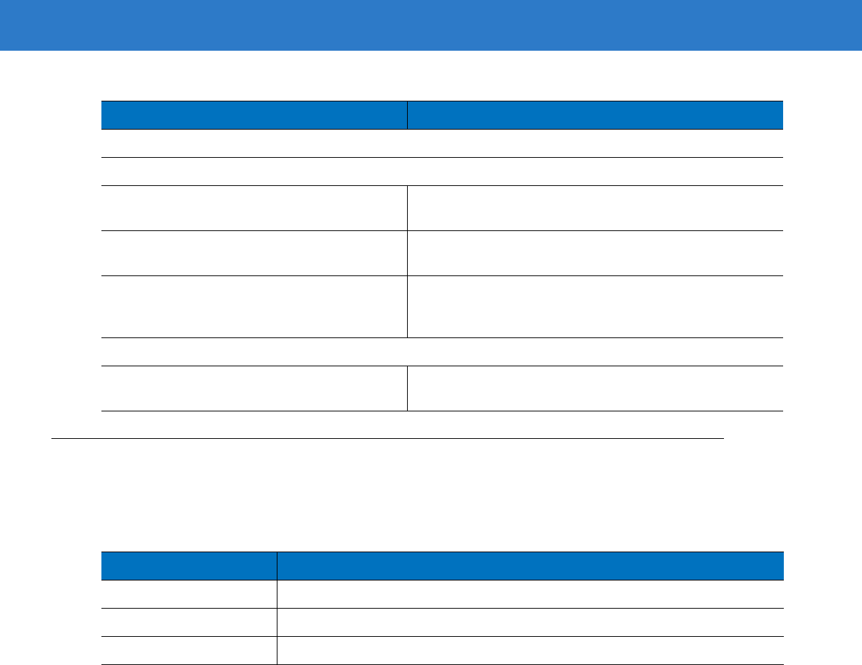
LED Definitions
In addition to beeper sequences, the scanner communicates with the user using a two-color LED display. Table 2-2
defines LED colors that display during scanning.
Host Specific
USB only
4 short high beeps Scanner has not completed initialization. Wait several
seconds and scan again.
Scanner gives a power-up beep after
scanning a USB Device Type. Communication with the bus must be established before the
scanner can operate at the highest power level.
This power-up beep occurs more than once. The USB bus may put the scanner in a state where power to
the scanner is cycled on and off more than once. This is
normal and usually happens when the host cold boots.
RS-232 only
1 short high beep A <BEL> character is received and Beep on <BEL> is
enabled.
Table 2-1
Beeper Definitions (Continued)
Beeper Sequence Indication
Table 2-2
Standard LED Definitions
LED Indication
Off No power is applied to the scanner, or the scanner is on and ready to scan.
Green A bar code was successfully decoded.
Red A data transmission error or scanner malfunction occurred.
2 - 4 Symbol LS4208 Product Reference Guide
Scan Patterns
The scanner emits several scanning patterns, described as follows. To select a pattern, see Scan Pattern on page
4-6.
Single-Line Only
The laser has no up and down scan line movement (no raster).
Figure 2-2
Single-Line Only Scan Pattern
Multi-Line Smart Raster
The scan line begins as a single line and moves up and down (rasters) when a partial scan of a bar code is
detected, or no bar code is decoded 500 ms after the trigger is pulled. If the scanner detects a PDF417
(Symbol LS4208-PR only), GS1 DataBar, or Composite Code, it immediately rasters, opening to a full, optimized
raster pattern as soon as the scanner is properly aligned over the bar code.
Figure 2-3
Multi-Line Smart Raster Scan Pattern
Multi-line Always Raster
Rastering (up and down scan line movement) begins immediately to decode 1D, PDF417 (Symbol LS4208-PR
only), GS1 DataBar, and Composite Codes.
Figure 2-4
Multi-Line Always Raster Scan Pattern
Single Scan Line Pattern
Open Raster Pattern
Y-Axis
Y-Axis
Horizontal Displacement (X - Axis)
Scanning 2 - 5
Scanning Modes
The Symbol LS4208 accommodates both hand-held and hands-free modes. In hand-held use, you pull the trigger
to activate the scan pattern and decode the bar code. In hands-free mode, the scanner sits in the Intellistand and
automatically decodes a bar code presented in its field of view.
Scanning in Hand-Held Mode
Install and program the scanner (see Setting Up the Scanner on page 1-3). For assistance, contact Motorola
Enterprise Mobility Support. See page xv for contact information.
To scan in hand-held mode:
1. Ensure all connections are secure. (See the host chapter for the scanner.)
2. Aim the scanner at the bar code.
3. Press the trigger.
Figure 2-5
Scanning in Hand-Held Mode
Upon successful decode, the scanner beeps and the LED turns green. For more information about beeper and
LED definitions, see Table 2-1 and Table 2-2.
Single-Line Mode Multi-Line Raster Mode
NOTE Scan line lengths vary depending on the scan line width selected (see Scan Line Width on page 4-7). A full
scan line width is the default. Medium and short scan line widths are useful for scanning menus or
pick-lists.
2 - 6 Symbol LS4208 Product Reference Guide
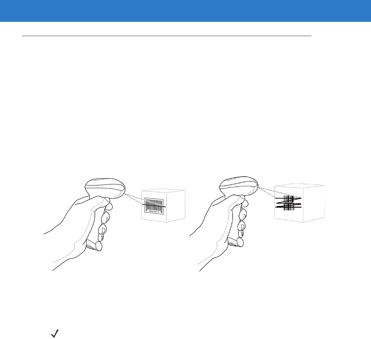
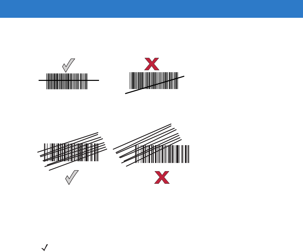
Aiming
On a typical UPC 100% hold the scanner between contact and 19 inches from the symbol (see Symbol LS4208
Decode Zone on page 2-11). When scanning using a single-line scan mode, ensure the scan line crosses every
bar and space of the symbol.
Figure 2-6
Acceptable and Incorrect Single-Line Aiming
When scanning using a multi-line raster mode, at least one scan line must cross every bar and space of the
symbol.
Figure 2-7
Acceptable and Incorrect Multi-Line Aiming
Regardless of the scan mode, the scan line is smaller when the scanner is closer to the symbol and larger when it
is farther from the symbol. Scan symbols with smaller bars or elements (mil size) closer to the scanner, and those
with larger bars or elements (mil size) farther from the scanner.
Do not hold the scanner directly over the bar code. Laser light reflecting directly back into the scanner from the bar
code is known as specular reflection. This specular reflection can make decoding difficult.
012345 012345
012345
012345
NOTE Scan line lengths vary depending on the scan line width selected (see Scan Line Width on page 4-7). A full
scan line width is the default. Medium and short scan line widths are useful for scanning menus or
pick-lists.
Scanning 2 - 7
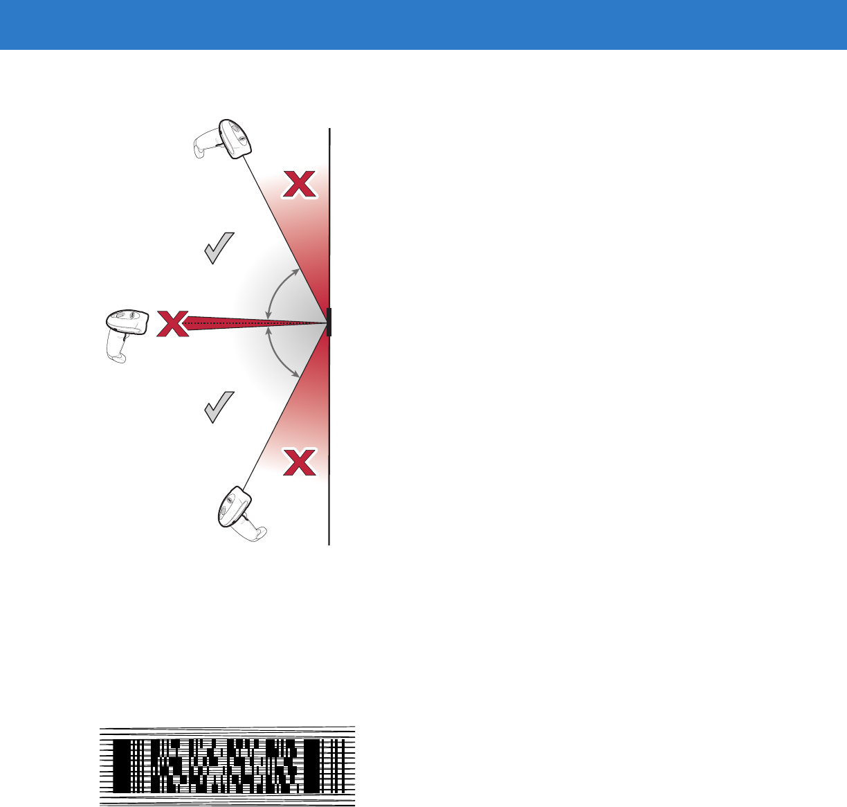
The scanner can be tilted up to 65° forward or back and achieve a successful decode (Figure 2-8). Simple practice
quickly shows what tolerances to work within.
Figure 2-8
Maximum Tilt Angles and Dead Zone
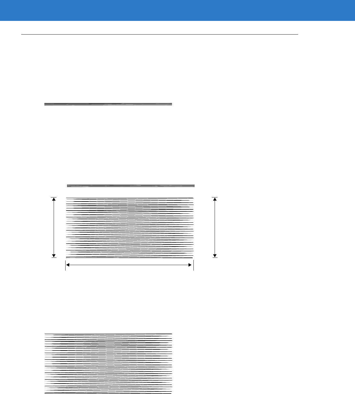
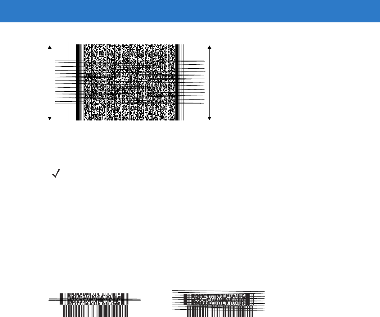
Scanning PDF Symbols
For optimal scanning performance, use rastering mode to scan PDF417 symbols. Adjust the raster to cover the
entire PDF symbol. For large PDF symbols, you may need to manually raster the scanner in order to cover the
entire symbol.
If the pattern does not cover the top and bottom of a PDF symbol, pull the scanner back until it does. Make sure the
scan pattern extends beyond the edges of the bar code.
Figure 2-9
Raster Pattern Expanded Over PDF417 Symbol
If the vertical scan pattern is not high enough to cover a “tall” PDF417 symbol, move the scanner slowly down
toward the bottom of the symbol, keeping the beam horizontal to the rows, and then slowly back upward to the top.
Alternatively, move the scanner further away from the bar code until the scan pattern covers a larger portion of the
bar code in the vertical direction.
65
o
65
o
2 - 8 Symbol LS4208 Product Reference Guide
Figure 2-10
Moving Scan Pattern Upward and Downward on “Tall” PDF Symbol
Keep the scan pattern parallel to the symbol rows. Upon successful decode, the scanner beeps and the LED turns
green. (For more information about beeper and LED definitions, see Table 2-1 and Table 2-2.)
Scanning Composite Bar Codes
Composite Code is a combination of a 1D symbol (GS1 DataBar, UPC/EAN or GS1-128) and a 2D symbol (CC-A,
CC-B or CC-C). When scanning a Composite Code:
•
Keep the scan pattern parallel to the symbol’s rows.
•
Hold the scanner as still as possible.
•
Hold the scanner at an angle which does not cause specular reflection.
•
Hold the scanner close for small symbols, and farther away for large symbols. Practice shows what works.
•
Aim the scan line at the middle of the 2D portion. The scan pattern rasters and decodes both the 2D and 1D
portion of the Composite Code.
Figure 2-11
Scanning Composite Codes
NOTE Raster height varies depending on the option selected (see Raster Height on page 4-8).
Aim at the center of the 2D portion Raster pattern expands to decode
both portions
Scanning 2 - 9
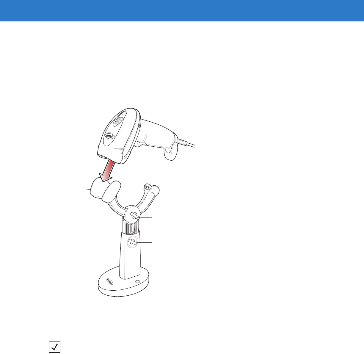
Scanning in Hands-Free Mode
The optional Intellistand adds greater flexibility to scanning operation. When the scanner is seated in the stand’s
“cup,” the scanner’s built-in sensor places the scanner in hands-free mode. When the scanner is removed from the
stand, it automatically switches modes to operate in its normal hand-held triggered mode.
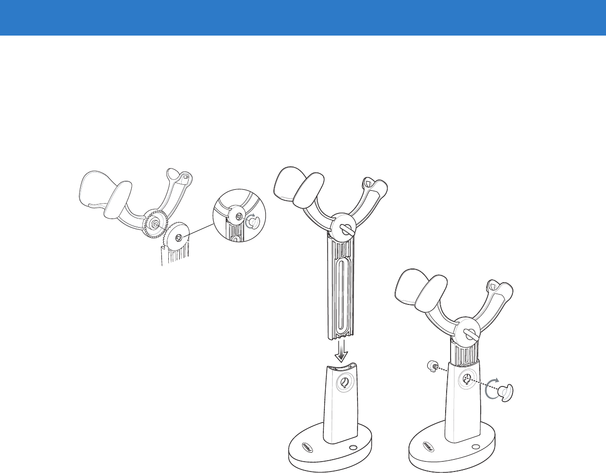
Assemble the Stand
Figure 2-12
Assembling Intellistand
2 - 10 Symbol LS4208 Product Reference Guide
Scanning with Intellistand
When the scanner is placed in the Intellistand, the scan pattern selected in hand-held triggered mode continues
(see Scan Pattern on page 4-6).
To operate the scanner in Intellistand:
1. Ensure the scanner is properly connected to the host (see the appropriate host chapter for information on host
connections).
2. Insert the scanner in Intellistand by placing the front of the scanner into the stand’s “cup.”
Figure 2-13
Inserting the Scanner in the Intellistand
3. Use the Intellistand’s adjustment knobs to adjust the height and angle of the scanner.
4. Present the bar code.
5. Upon successful decode, the scanner beeps and the LED turns green. For more information about beeper and
LED definitions, see Table 2-1 and Table 2-2.
Scanner Holder
Height Adjustment Knob
Angle Adjustment Knob
Cup
NOTE When the bar code is in view, the scanner emits a full scan line. After 3 minutes, the
scanner automatically switches to a reduced scan line. After 1 hour, the scanner automatically
switches to blink mode.
Scanning 2 - 11
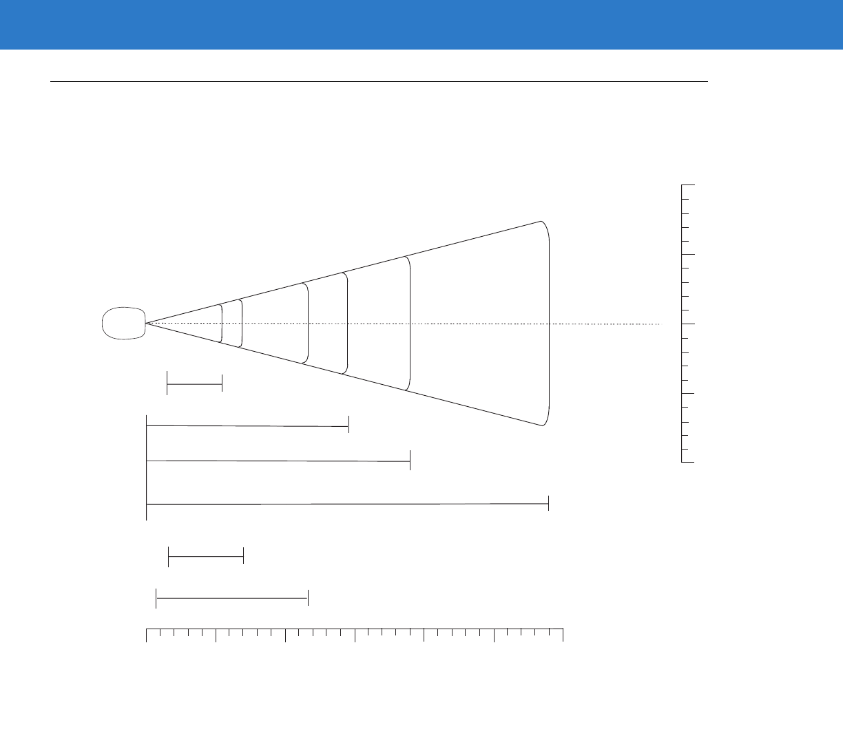
Symbol LS4208 Decode Zone
Figure 2-14
Symbol LS4208 Decode Zone
Note: Typical performance at 73° F (23° C) on
high quality symbols in normal room light.
LS4208
* Minimum distance determined by symbol length and scan angle
** LS4208-PR (PDF417) version only
Depth of Field
*
5 mil 5.5
10 mil
29
20 mil
1.5
13 mil 19
14.5
in.
cm
0
0
5
12.7
10
25.4
15
38.1
20
50.8
25
63.5
30
76.2
W
i
d
t
h
o
f
F
i
e
l
d
00
12.7
25.4
5
10
in. cm
12.75
25.410
** 6.6 mil PDF417 (3:1)
7
1.5
** 10 mil PDF417 (3:1)
11.75
0.75

2 - 12 Symbol LS4208 Product Reference Guide

Chapter 3 Maintenance, Troubleshooting &
Technical Specifications
Introduction
This chapter provides suggested scanner maintenance, troubleshooting, technical specifications, and signal
descriptions (pinouts).
Maintenance
Cleaning the exit window is the only maintenance required. A dirty window may affect scanning accuracy.
•
Do not allow any abrasive material to touch the window
•
Remove any dirt particles with a damp cloth
•
Wipe the window using a tissue moistened with ammonia/water
•
Do not spray water or other cleaning liquids directly into the window.
3 - 2 Symbol LS4208 Product Reference Guide
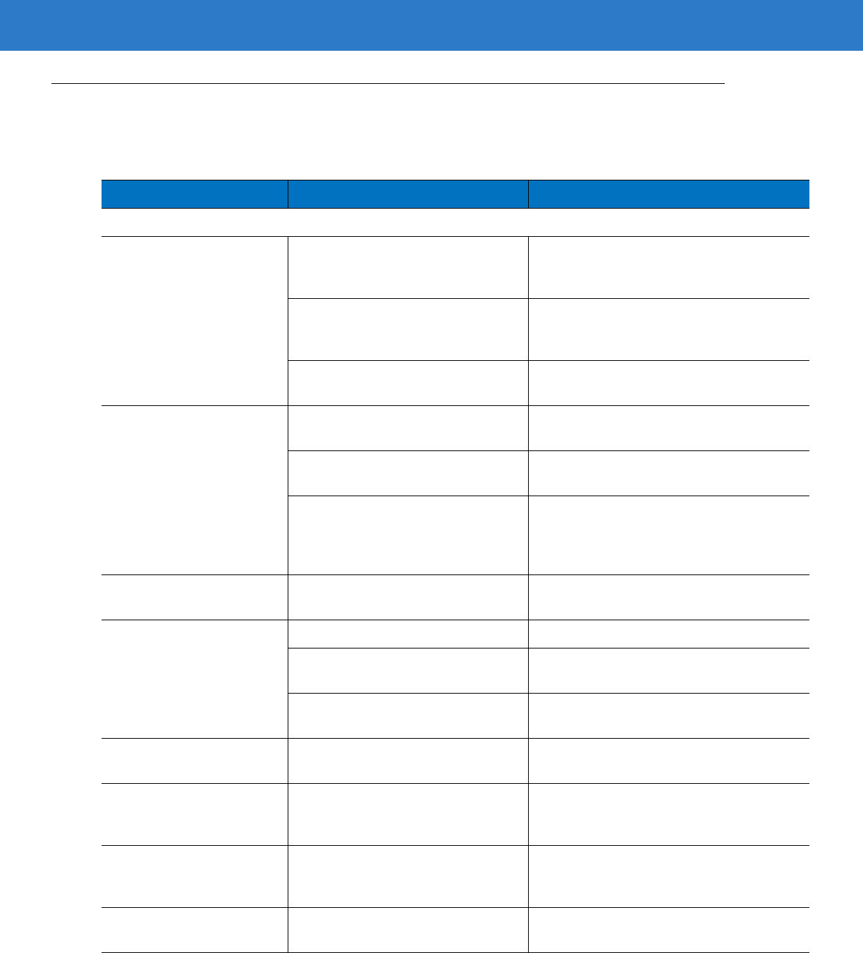
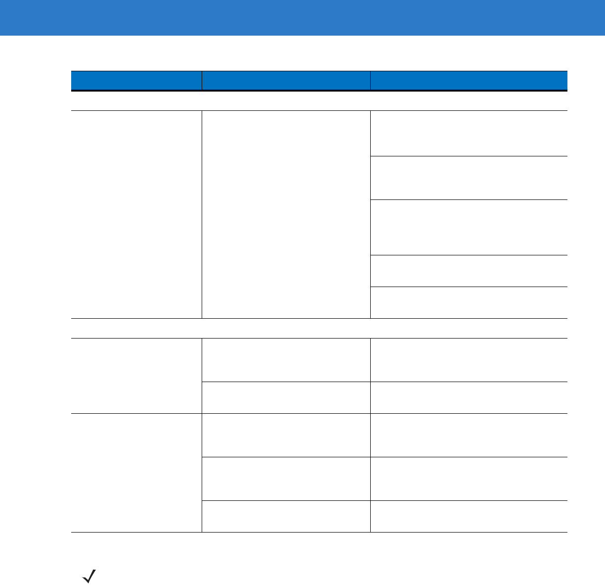
Troubleshooting
Table 3-1
Troubleshooting
Problem Possible Causes Possible Solutions
Beeper Indications
The scanner emits frequent
beeps. No power to the scanner. Check the system power. If the
configuration requires a power supply,
re-connect the power supply.
Incorrect host interface cable is used. Verify that the correct host interface cable is
used. If not, connect the correct host
interface cable.
Interface/power cables are loose. Check for loose cable connections and
re-connect cables.
Scanner emits low/high/low
beeps. ADF transmit error. See
Chapter 14, Advanced Data
Formatting
.
Invalid ADF rule is detected. See
Chapter 14, Advanced Data
Formatting
.
The Code 39 buffer was erased or
there was an attempt to clear or
transmit an empty buffer.
Normal when scanning the Code 39
Buffering
Clear Buffer
bar code or upon
attempt to transmit an empty Code 39
buffer.
Scanner emits low/high
beeps. Input error, incorrect bar code or
Cancel
bar code was scanned. Scan the correct numeric bar codes within
range for the parameter programmed.
Scanner emits
low/high/low/high beeps. Out of host parameter storage space. Scan
Default Parameters on page 4-3
.
Out of memory for ADF rules. Reduce the number of ADF rules or the
number of steps in the ADF rules.
During programming, indicates out of
ADF parameter storage space. Erase all rules and re-program with shorter
rules.
Scanner emits high/low
beeps. The scanner is buffering Code 39
data. Normal.
Scanner emits
high/high/high/low beeps. RS-232 receive error. Normal during host reset. Otherwise, set the
scanner's RS-232 parity to match the host
setting.
Scanner emits four long low
beeps. A transmission error was detected in
a scanned symbol. The data is
ignored.
This occurs if a unit is not properly
configured. Check option setting.
Scanner emits four short
high beeps (USB only). Scanner has not completed
initialization. Wait several seconds and scan again.

Maintenance, Troubleshooting & Technical Specifications 3 - 3
Decoding Bar Codes
Scanner emits the laser, but
does not decode the bar
code.
Scanner is not programmed for the
correct bar code type. Program the scanner to read that type of bar
code. See
Chapter 12, Symbologies
.
Bar code symbol is unreadable. Scan test symbols of the same bar code
type to determine if the bar code is defaced.
Distance between scanner and bar
code is incorrect. Move the scanner closer to or further from
the bar code. See
Symbol LS4208 Decode
Zone on page 2-11
.
The scan line is not crossing every
bar and space of the symbol. Move the symbol until the scan line is within
the acceptable aiming pattern. See
Figure
2-6 on page 2-6
.
Scanner decodes bar code,
but does not transmit the
data to the host.
Scanner is not programmed for the
correct host type. Scan the appropriate host type
programming bar code. See the chapter
corresponding to the host type.
Interface cable is loose. Check for loose cable connection and
re-connect cable.
Scanner emits five long low
beeps after a bar code is
decoded.
Conversion or format error was
detected.
The scanner’s conversion
parameters are not properly
configured.
Ensure the scanner’s conversion
parameters are properly configured.
Conversion or format error was
detected.
An ADF rule was set up with
characters that can't be sent for the
host selected.
Change the ADF rule, or change to a host
that can support the ADF rule.
Conversion or format error was
detected.
A bar code was scanned with
characters that can't be sent for that
host.
Change the bar code, or change to a host
that can support the bar code.
Table 3-1
Troubleshooting (Continued)
Problem Possible Causes Possible Solutions
3 - 4 Symbol LS4208 Product Reference Guide
Host Displays
Host displays scanned data
incorrectly. Scanner is not programmed to work
with the host. Ensure the proper host is selected.
Scan the appropriate host type
programming bar code.
For RS-232, set the scanner's
communication parameters to match the
host's settings.
For a USB HID keyboard or Keyboard
Wedge configuration, program the system
for the correct keyboard type and language,
and turn off the CAPS LOCK key.
Program the proper editing options (e.g.,
ADF, UPC-E to UPC-A Conversion).
Check the scanner’s host type parameters
or editing options.
Trigger
Nothing happens when the
trigger is pulled. No power to the scanner. Check the system power. If the
configuration requires a power supply,
re-connect the power supply.
Interface/power cables are loose. Check for loose cable connections and
re-connect cables.
The laser does not appear
when the trigger is pulled. No power to the scanner. Check the system power. If the
configuration requires a power supply,
re-connect the power supply.
Incorrect host interface cable is used. Verify that the correct host interface cable is
used. If not, connect the correct host
interface cable.
Interface/power cables are loose. Check for loose cable connections and
re-connect cables.
Table 3-1
Troubleshooting (Continued)
Problem Possible Causes Possible Solutions
NOTE If after performing these checks the symbol still does not scan, contact the distributor or Motorola
Enterprise Mobility Support. See page xv for contact information.
Maintenance, Troubleshooting & Technical Specifications 3 - 5
Technical Specifications
Table 3-2
Technical Specifications
Item Description
Physical Characteristics
Dimensions: 6.7 in. H x 3.7 in. L x 2.7 in. W
(17 cm H x 9.3 cm L x 6.8 cm W)
Weight (without cable) Approximately 6.4 oz. (181 g)
Voltage & Current
Symbol LS4208-SR
Symbol LS4208-PR
5 +/-10%VDC @ 140 mA (Stand by: <35 mA)
5 +/-10%VDC @ 155 mA (Stand by: <60 mA)
Color Cash Register White or Twilight Black
Performance Characteristics
Light Source (Laser) 650nm laser diode
Motor Frequency 50Hz
Decode Rate 200 decodes per second
Roll Tolerance ± 35°
Pitch Tolerance ± 60°
Yaw Tolerance ± 60°
Nominal Working Distance See
Symbol LS4208 Decode Zone on page 2-11
Minimum Resolution 5 mil (linear bar codes)
5 mil (uPDF & PDF, 3:1, Y:X aspect ratio)
Print Contrast Minimum 25% minimum reflectance
Multi-Line Aiming Coverage At 5 in. reading distance: ~ 0.5 in. (1.3 cm)
At 10 in. reading distance: ~ 1 in. (2.5 cm)
Motion Tolerances Horizontal Velocity: 200 in. (508 cm) / sec
Vertical Velocity: 200 in. (508 cm) / sec
Angular Velocity: 200 in. (508 cm) / sec
Decode Capability UPC/EAN and with supplementals, Bookland EAN, Code 39, Code 39
Full ASCII, Trioptic Code 39, GS1DataBar Variants, GS1-128, Code
128, Code 128 Full ASCII, Code 93, Codabar (NW1), Code 11,
Interleaved 2 of 5, Discrete 2 of 5, Chinese 2 of 5, MSI, IATA, Code 32,
PDF417, MicroPDF417, Composite Codes

3 - 6 Symbol LS4208 Product Reference Guide
Interfaces Supported RS-232C (Standard, Nixdorf, ICL, & Fujitsu); IBM 468x/469x; Keyboard
Wedge; USB (Standard, IBM SurePOS, Macintosh); Laser/Wand
Emulation.
Synapse Adaptive Connectivity allows for connectivity to interfaces
above and many non-standard interfaces.
User Environment
Operating Temperature 32° to 122° F (0° to 50° C)
Storage Temperature -40° to 158° F (-40° to 70° C)
Humidity 5% to 95%, non-condensing
Drop Specifications Withstands multiple 6 ft./1.825 m drops to concrete
Ambient Light Immunity Immune to normal artificial indoor and natural outdoor (direct sunlight)
lighting conditions
EAS Support Optional Checkpoint Electronic Article Surveillance (EAS)
Beeper Volume User-selectable: three levels
Beeper Tone User-selectable: three tones
ESD 15 kV air discharge
8 kV indirect discharge
Regulatory
Electrical Safety UL1950, CSA C22.2 No. 950, EN60950/IEC950
Laser Safety CDRH Class II, IEC Class 2
EMI/RFI FCC Part 15 Class B, ICES-003 Class B, European Union EMC
Directive, Australian SMA
Table 3-2
Technical Specifications (Continued)
Item Description
Maintenance, Troubleshooting & Technical Specifications 3 - 7
Scanner Signal Descriptions
Figure 3-1
Scanner Cable Pin-outs
Cable interface port
Interface cable
modular connector
Bottom of
scanner
PIN 1
PIN 10

3 - 8 Symbol LS4208 Product Reference Guide
The signal descriptions in Table 3-3 apply to the connector on the scanner and are for reference only.
Table 3-3
Scanner Signal Pin-outs
Pin IBM Synapse RS-232 Keyboard
Wedge Wand USB
1 Reserved SynClock Reserved Reserved Reserved Jump to Pin 6
2 Power Power Power Power Power Power
3 Ground Ground Ground Ground Ground Ground
4 IBM_A(+) Reserved TxD KeyClock DBP Reserved
5 Reserved Reserved RxD TermData CTS D +
6 IBM_B(-) SynData RTS KeyData RTS Jump to Pin 1
7 Reserved Reserved CTS TermClock Reserved D -
8 Reserved Reserved Reserved Reserved Reserved Reserved
9 EAS EAS EAS EAS EAS EAS
10EASEASEASEASEASEAS

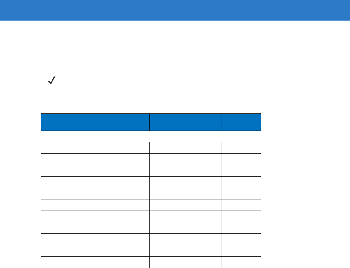
Chapter 4 User Preferences
Introduction
If desired, program the scanner to perform various functions, or activate different features. This chapter describes
each user preference feature and provides the programming bar codes necessary for selecting these features.
The scanner ships with the settings shown in the User Preferences Default Table on page 4-2 (also see Appendix
A, Standard Default Parameters for all host device and miscellaneous defaults). If the default values suit
requirements, programming may not be necessary.
To set feature values, scan a single bar code or a short bar code sequence. The settings are stored in non-volatile
memory and are preserved even when the scanner is powered down.
If not using a Synapse or USB cable, select a host type (see each host chapter for specific host information) after
the power-up beeps sound. This is only necessary upon the first power-up when connected to a new host.
To return all features to their default values, see Default Parameters on page 4-3. Throughout the programming bar
code menus, default values are indicated with asterisks (*).
Scanning Sequence Examples
In most cases, scanning one bar code sets the parameter value. For example, to set the beeper tone to high, scan
the High Frequency (beeper tone) bar code listed under Beeper Tone on page 4-4. The scanner issues a fast
warble beep and the LED turns green, signifying a successful parameter entry.
Other parameters, such as Serial Response Time-Out or Data Transmission Formats, require scanning several
bar codes. See these parameter descriptions for this procedure.
Errors While Scanning
Unless otherwise specified, when an error is made during a scanning sequence, just re-scan the correct
parameter.
*High Frequency Feature/Option
* Indicates Default
4 - 2 Symbol LS4208 Product Reference Guide
User Preferences Parameter Defaults
Table 4-1 lists the defaults for user preferences parameters. To change any option, scan the appropriate bar
code(s) provided in the User Preferences section beginning on page 4-3.
NOTE See Appendix A, Standard Default Parameters for all user preferences, hosts, symbologies, and
miscellaneous default parameters.
Table 4-1
User Preferences Default Table
Parameter Default Page
Number
User Preferences
Set Default Parameter Restore Defaults 4-3
Parameter Bar Code Scanning Enable 4-4
Beeper Tone Medium 4-4
Beeper Volume High 4-5
Power Mode Continuous On 4-5
Scan Pattern Multi-line Always Raster 4-6
Scan Line Width Full Width 4-7
Raster Height Adjustable Raster 4-8
Laser On Time 3.0 Sec 4-9
Beep After Good Decode Enable 4-9
PDF Decode Feedback Disable 4-10

User Preferences 4 - 3
User Preferences
Default Parameters
The scanner can be reset to two types of defaults: factory defaults or custom defaults. Scan the appropriate bar
code below to reset the scanner to its default settings and/or set the scanner’s current settings as the custom
default.
•
Restore Defaults - Resets all default parameters as follows:
•If custom default values were configured (see Write to Custom Defaults), the custom default values are
set for all parameters each time the Restore Defaults bar code below is scanned.
•If no custom default values were configured, the factory default values are set for all parameters each time
the Restore Defaults bar code below is scanned. (For factory default values, see Table A-1 on page A-1.)
•
Set Factory Defaults - Scan the Set Factory Defaults bar code below to eliminate all custom default values
and set the scanner to factory default values. (For factory default values, see Table A-1 on page A-1.)
•
Write to Custom Defaults - Custom default parameters can be configured to set unique default values for all
parameters. After changing all parameters to the desired default values, scan the Write to Custom Defaults
bar code below to configure custom defaults.
*Restore Defaults
Set Factory Defaults
Write to Custom Defaults
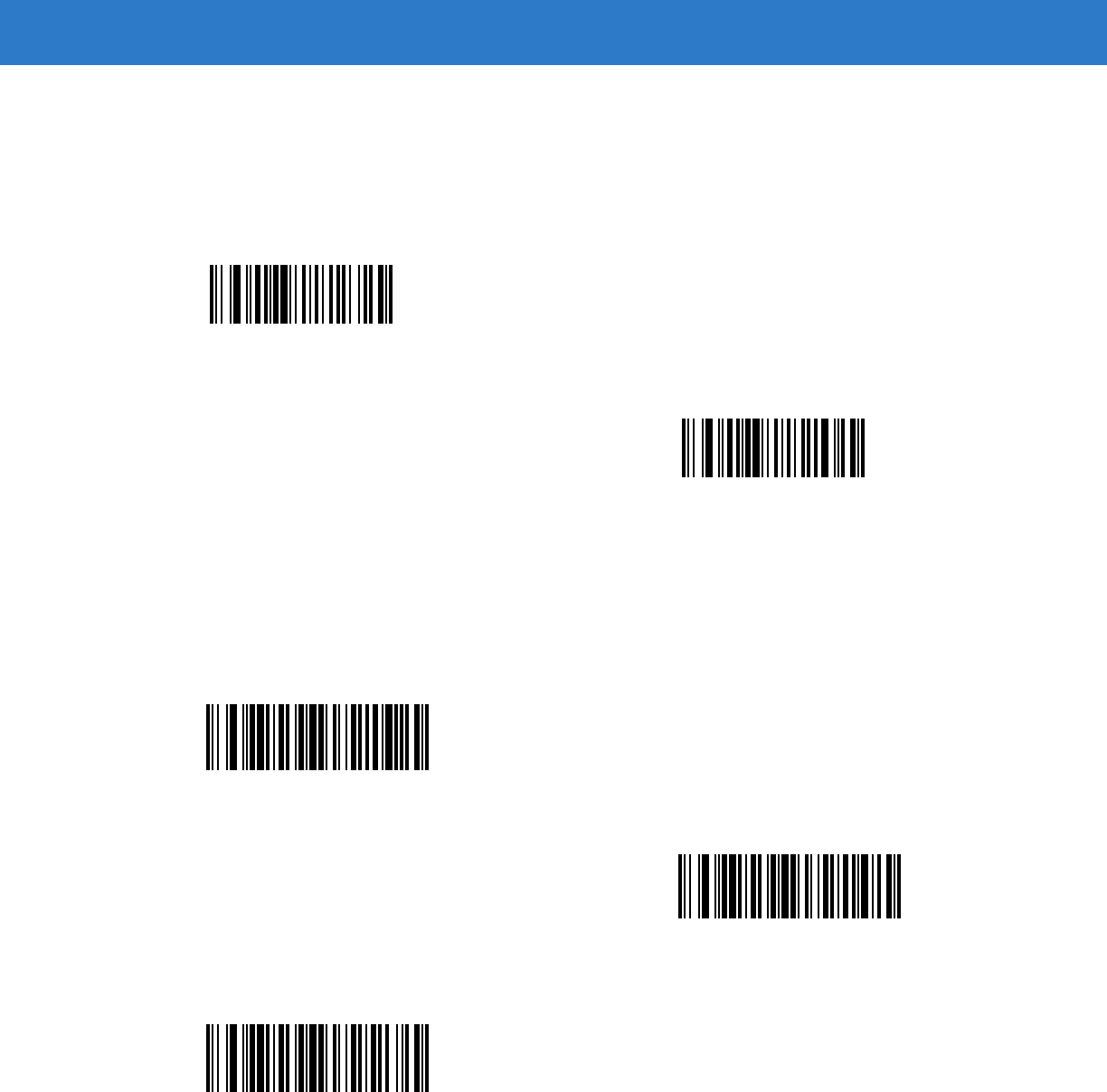
4 - 4 Symbol LS4208 Product Reference Guide
Parameter Bar Code Scanning
To disable the decoding of parameter bar codes, including the Set Defaults parameter bar codes, scan the
Disable Parameter Scanning bar code below. To enable decoding of parameter bar codes, scan Enable
Parameter Scanning.
Beeper Tone
To select a decode beep frequency (tone), scan the Low Frequency, Medium Frequency, or High Frequency bar
code.
*Enable Parameter Bar Code Scanning
(01h)
Disable Parameter Bar Code Scanning
(00h)
Low Frequency
*Medium Frequency
(Optimum Settings)
High Frequency
User Preferences 4 - 5
Beeper Volume
To select a beeper volume, scan the Low Volume, Medium Volume, or High Volume bar code.
Power Mode
This parameter determines whether or not power remains on after a decode attempt. When in reduced power
mode, the scanner enters into a low power consumption mode to preserve battery life after each decode attempt.
When in continuous power mode, power remains on after each decode attempt.
Low Volume
Medium Volume
*High Volume
*Continuous On
Reduced Power Mode

4 - 6 Symbol LS4208 Product Reference Guide
Scan Pattern
This parameter determines the pattern (mode) of scanning. Scan the appropriate bar code below to set the
scanning mode.
•
Single-line Only - Scan Single-line Only for a single-line scan mode. The laser has no up and down scan
line movement (no raster). (For an example of a single-line scan, see Figure 2-6 on page 2-6.)
•
Multi-line Smart Raster - The scan line begins as a single line, and immediately rasters upon seeing a
stacked GS1 DataBar code or a 2D variant. (For an example of a multi-line scan, see Figure 2-7 on page
2-6.)
•
Multi-line Always Raster (default) - Scan Multi-line Always Raster for rastering (up and down scan line
movement) to begin immediately.
Single-line Only
(No Raster)
Multi-line Smart Raster
*Multi-line Always Raster

User Preferences 4 - 7
Scan Line Width
Scan a bar code below to set the scan line width.
*Full Width
Medium Width
Small Width

4 - 8 Symbol LS4208 Product Reference Guide
Raster Height
This parameter determines the scanner’s raster height when scanning PDF symbols only.
•
Short Raster - Scan Short Raster to use the standard 1D raster height of approximately 4o. This option
provides the best performance on MicroPDF and short PDF symbols.
•
Tall Raster - Scan Tall Raster for a raster of approximately 50% taller than the short raster, opening to about
6o and slowing to capture bar code data more efficiently. This provides the best performance on tall PDF
symbols.
•
Adjustable Raster (default) - This option starts as a short raster, then opens to a tall raster and slows half a
second later. Use this option when scanning a variety of symbol heights.
Short Raster
Tall Raster
*Adjustable Raster

User Preferences 4 - 9
Laser On Time
This parameter sets the maximum time that decode processing continues during a scan attempt. It is
programmable in 0.1 second increments from 0.5 to 9.9 seconds. The default Laser On Time is 3.0 seconds.
To set a Laser On Time, scan the bar code below. Next, scan two numeric bar codes beginning on page D-1 in
Appendix D, Numeric Bar Codes that correspond to the desired on time. Single digit numbers must have a leading
zero. For example, to set an On Time of 0.5 seconds, scan the bar code below, then scan the “0” and “5” bar
codes. If an error is made, or the selection needs to be changed, scan Cancel on page D-3.
Beep After Good Decode
Scan a bar code below to select whether or not the scanner beeps after a good decode. If Do Not Beep After
Good Decode is selected, the beeper still operates during parameter menu scanning and indicates error
conditions.
Laser On Time
*Beep After Good Decode
(Enable)
Do Not Beep After Good Decode
(Disable)

4 - 10 Symbol LS4208 Product Reference Guide
PDF Decode Feedback
Scan a bar code below to select whether or not the scanner emits a clicking sound during PDF417 decoding.
This clicking helps the user ensure proper alignment, motion, and distance during decoding. The scanner issues a
standard decode beep upon successfully decoding the bar code.
Enable PDF Decode Feedback
*Disable PDF Decode Feedback

Chapter 5 Keyboard Wedge Interface
Introduction
This chapter describes how to set up a Keyboard Wedge interface with the scanner. With this interface, the
scanner is connected between the keyboard and host computer, and translates bar code data into keystrokes. The
host computer accepts the keystrokes as if they originated from the keyboard. This mode adds bar code reading
functionality to a system designed for manual keyboard input. Keyboard keystrokes are simply passed through.
Throughout the programming bar code menus, default values are indicated with asterisks (*).
*North American Feature/Option
* Indicates Default
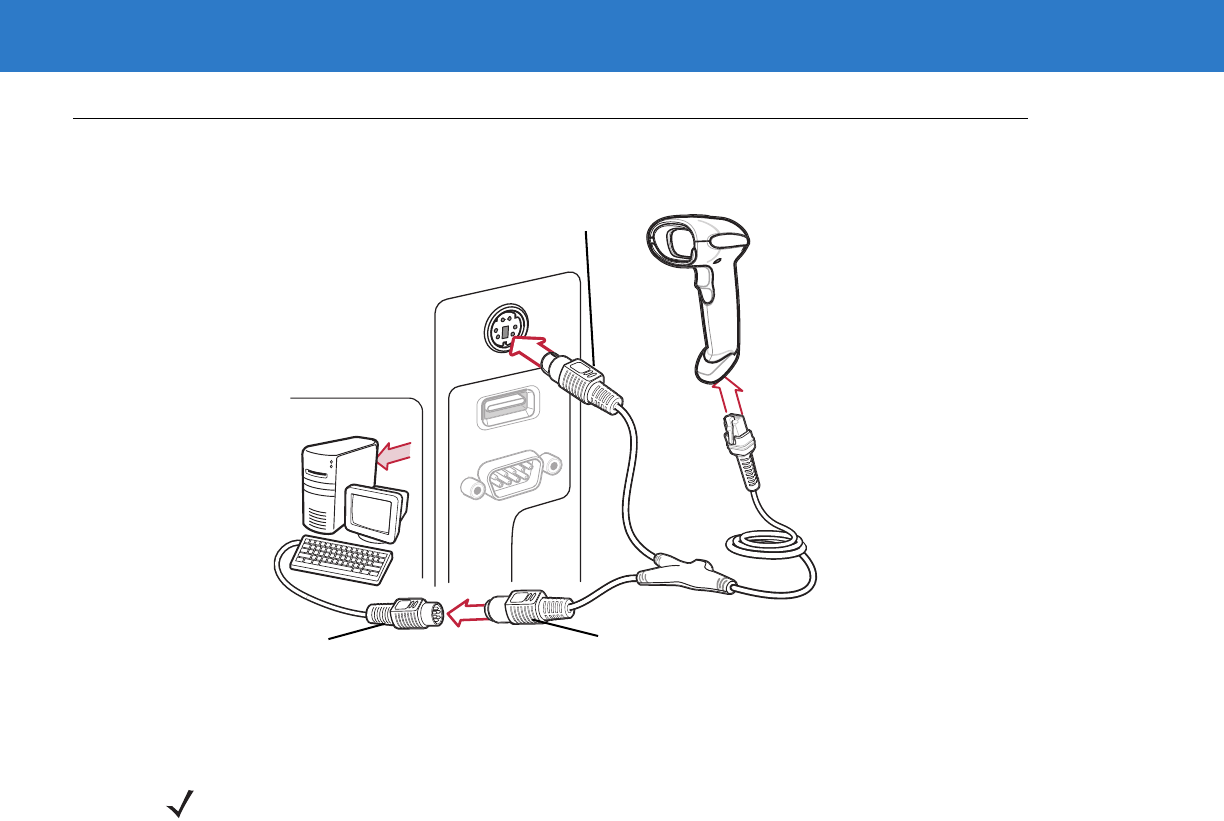
5 - 2 Symbol LS4208 Product Reference Guide
Connecting a Keyboard Wedge Interface
Figure 5-1
Keyboard Wedge Connection with Y-cable
To connect the Keyboard Wedge interface Y-cable:
1. Turn off the host and unplug the keyboard connector.
2. Attach the modular connector of the Y-cable to the cable interface port on the scanner. (See Installing the
Interface Cable on page 1-3.)
3. Connect the round male DIN host connector of the Y-cable to the keyboard port on the host device.
4. Connect the round female DIN keyboard connector of the Y-cable to the keyboard connector.
5. If needed, attach the optional power supply to the connector in the middle of the Y-cable.
6. Ensure that all connections are secure.
7. Turn on the host system.
8. Select the Keyboard Wedge host type by scanning the appropriate bar code from Keyboard Wedge Host
Parameters on page 5-4.
9. To modify any other parameter options, scan the appropriate bar codes in this chapter.
Male DIN Connector
Female DIN Connector
Keyboard Connector
NOTE Interface cables vary depending on configuration. The connectors illustrated in Figure 5-1 are examples
only. The connectors may be different than those illustrated, but the steps to connect the scanner are the
same.
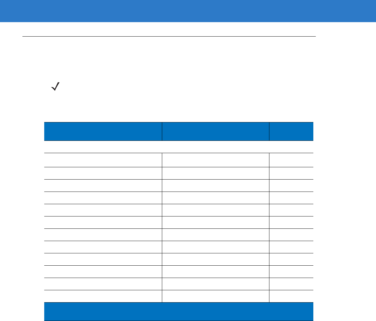
Keyboard Wedge Interface 5 - 3
Keyboard Wedge Parameter Defaults
Table 5-1 lists the defaults for Keyboard Wedge host parameters. To change any option, scan the appropriate bar
code(s) in the Keyboard Wedge Host Parameters section beginning on page 5-4.
NOTE See Appendix A, Standard Default Parameters for all user preferences, hosts, symbologies, and
miscellaneous default parameters.
Table 5-1
Keyboard Wedge Host Default Table
Parameter Default Page
Number
Keyboard Wedge Host Parameters
Keyboard Wedge Host Type IBM PC/AT& IBM PC Compatibles
1
5-4
Country Types (Country Codes) North American 5-5
Ignore Unknown Characters Send 5-6
Keystroke Delay No Delay 5-7
Intra-Keystroke Delay Disable 5-7
Alternate Numeric Keypad Emulation Disable 5-8
Caps Lock On Disable 5-8
Caps Lock Override Disable 5-9
Convert Wedge Data No Convert 5-10
Function Key Mapping Disable 5-10
FN1 Substitution Disable 5-11
Send and Make Break Send 5-11
1
User selection is required to configure this interface and this is the most common
selection.
5 - 4 Symbol LS4208 Product Reference Guide
Keyboard Wedge Host Parameters
Keyboard Wedge Host Types
Select the Keyboard Wedge host by scanning one of the bar codes below.
IBM PC/AT & IBM PC Compatibles1
IBM AT Notebook
NCR 7052
NOTE 1User selection is required to configure this interface and this is the most common selection.
Keyboard Wedge Interface 5 - 5
Keyboard Wedge Country Types (Country Codes)
Scan the bar code corresponding to the keyboard type. If the keyboard type is not listed, see Alternate Numeric
Keypad Emulation on page 5-8.
*North American
German Windows
French Windows
French Canadian Windows 95/98
French Canadian Windows XP/2000
Spanish Windows
Italian Windows
5 - 6 Symbol LS4208 Product Reference Guide
Ignore Unknown Characters
Unknown characters are characters the host does not recognize. When Send Bar Codes With Unknown
Characters is selected, all bar code data is sent except for unknown characters, and no error beeps sound on the
scanner. When Do Not Send Bar Codes With Unknown Characters is selected, bar code data is sent up to the
first unknown character, then the scanner issues an error beep.
Keyboard Wedge Country Types (continued)
Swedish Windows
UK English Windows
Japanese Windows
Portuguese-Brazilian Windows
*Send Bar Codes with Unknown Characters
Do Not Send Bar Codes with Unknown Characters
Keyboard Wedge Interface 5 - 7
Keystroke Delay
This is the delay in milliseconds between emulated keystrokes. Scan a bar code below to increase the delay when
hosts require a slower transmission of data.
Intra-Keystroke Delay
When enabled, an additional delay is inserted between each emulated key depression and release. This sets the
Keystroke Delay parameter to a minimum of 5 msec as well.
*No Delay
Medium Delay (20 msec)
Long Delay (40 msec)
Enable Intra-Keystroke Delay
*Disable Intra-Keystroke Delay
5 - 8 Symbol LS4208 Product Reference Guide
Alternate Numeric Keypad Emulation
This allows emulation of most other country keyboard types not listed in Keyboard Wedge Country Types (Country
Codes) on page 5-5 in a Microsoft® operating system environment.
Caps Lock On
When enabled, the scanner emulates keystrokes as if the Caps Lock key is always pressed. Note that if both Caps
Lock On and Caps Lock Override are enabled, Caps Lock Override takes precedence.
Enable Alternate Numeric Keypad
*Disable Alternate Numeric Keypad
Enable Caps Lock On
*Disable Caps Lock On

Keyboard Wedge Interface 5 - 9
Caps Lock Override
When enabled, on AT or AT Notebook hosts, the keyboard ignores the state of the Caps Lock key. Therefore, an ‘A’
in the bar code is sent as an ‘A’ no matter what the state of the keyboard’s Caps Lock key.
Note that if both Caps Lock On and Caps Lock Override are enabled, Caps Lock Override takes precedence.
Enable Caps Lock Override
*Disable Caps Lock Override
5 - 10 Symbol LS4208 Product Reference Guide
Convert Wedge Data
When enabled, the scanner will convert all bar code data to the selected case.
Function Key Mapping
ASCII values under 32 are normally sent as control key sequences (see Table 5-2 on page 5-13). When this
parameter is enabled, the keys in bold are sent in place of the standard key mapping. Table entries that do not
have a bold entry remain the same whether or not this parameter is enabled.
Convert to Upper Case
Convert to Lower Case
*No Convert
Enable Function Key Mapping
*Disable Function Key Mapping
Keyboard Wedge Interface 5 - 11
FN1 Substitution
When enabled, the scanner replaces FN1 characters in a GS1-128 bar code with a keystroke chosen by the user
(see FN1 Substitution Values on page 13-6).
Send Make and Break
When enabled, the scan codes for releasing a key are not sent.
Enable FN1 Substitution
*Disable FN1 Substitution
*Send Make and Break Scan Codes
Send Make Scan Code Only
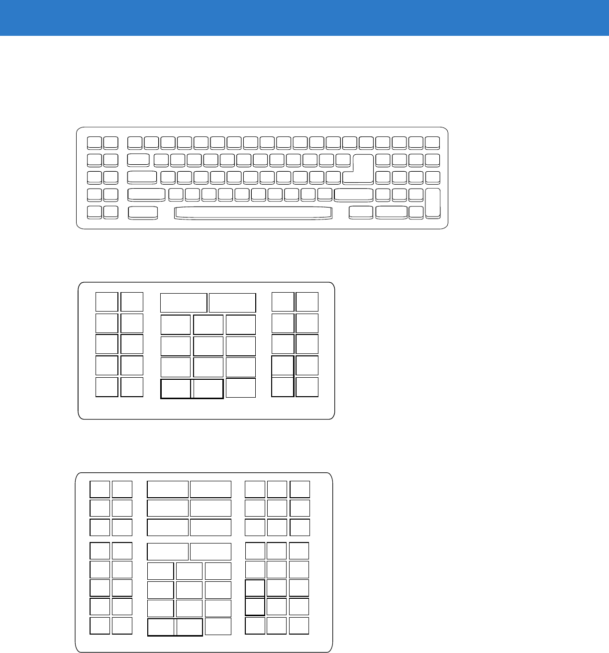
5 - 12 Symbol LS4208 Product Reference Guide
Keyboard Maps
The following keyboard maps are provided for prefix/suffix keystroke parameters. To program the prefix/suffix
values, see the bar codes on page 13-3.
Figure 5-2
IBM PC/AT
Figure 5-3
NCR 7052 32-KEY
Figure 5-4
NCR 7052 58-KEY
5001 5002
5003 5004
5005 5006
5007 5008
5009 5010
7009
7008
7013
7012
7004
7011
7003
7002
7014
5007 5008
5010
5002
5003 5004
5005 5006
1046
1045
5014
1043
5013
5015
5016
5018
5019
5001
5017
7013
5011
(7013 if double key)
(1048 if double key)
1048 5012
5009
5007 5008
5010
5002
5003 5004
5005 5006
1046
1045
5014
1043
5013
5015
5016
5018
5019
1086
1087
1088
1089
1090
5001
1066
1072 1073
1079 1080
1065 1070
1076 1077
1083 1084
1071
1078
1085
1069
5017
7013
5011
1082
1075
1068
1067
(1043 if double key)
(1048 if double key)
1048 5012
5009
1074
1081
Keyboard Wedge Interface 5 - 13
ASCII Character Set for Keyboard Wedge
NOTE Code 39 Full ASCII interprets the bar code special character ($ + % /) preceding a Code 39 character and
assigns an ASCII character value to the pair. For example, when Code 39 Full ASCII is enabled and a +B
is scanned, it is interpreted as b, %J as ?, and %V as @. Scanning ABC%I outputs the keystroke
equivalent of ABC >.
Table 5-2
Keyboard Wedge ASCII Character Set
ASCII Value Full ASCII Code 39
Encode Character Keystroke
1001 $A CTRL A
1002 $B CTRL B
1003 $C CTRL C
1004 $D CTRL D
1005 $E CTRL E
1006 $F CTRL F
1007 $G CTRL G
1008 $H CTRL H/
BACKSPACE
1
1009 $I CTRL I/
HORIZONTAL TAB
1
1010 $J CTRL J
1011 $K CTRL K
1012 $L CTRL L
1013 $M CTRL M/
ENTER
1
1014 $N CTRL N
1015 $O CTRL O
1016 $P CTRL P
1017 $Q CTRL Q
1018 $R CTRL R
1019 $S CTRL S
1020 $T CTRL T
1021 $U CTRL U
1
The keystroke in bold is sent only if the “Function Key Mapping” is
enabled. Otherwise, the unbolded keystroke is sent.

5 - 14 Symbol LS4208 Product Reference Guide
1022 $V CTRL V
1023 $W CTRL W
1024 $X CTRL X
1025 $Y CTRL Y
1026 $Z CTRL Z
1027 %A CTRL [ /
ESC
1
1028 %B CTRL \
1029 %C CTRL ]
1030 %D CTRL 6
1031 %E CTRL -
1032 Space Space
1033 /A !
1034 /B “
1035 /C #
1036 /D $
1037 /E %
1038 /F &
1039 /G ‘
1040 /H (
1041 /I )
1042 /J *
1043 /K +
1044 /L ,
1045 - -
1046 . .
1047 /O /
1048 0 0
1049 1 1
Table 5-2
Keyboard Wedge ASCII Character Set (Continued)
ASCII Value Full ASCII Code 39
Encode Character Keystroke
1
The keystroke in bold is sent only if the “Function Key Mapping” is
enabled. Otherwise, the unbolded keystroke is sent.

Keyboard Wedge Interface 5 - 15
1050 2 2
1051 3 3
1052 4 4
1053 5 5
1054 6 6
1055 7 7
1056 8 8
1057 9 9
1058 /Z :
1059 %F ;
1060 %G <
1061 %H =
1062 %I >
1063 %J ?
1064 %V @
1065 A A
1066 B B
1067 C C
1068 D D
1069 E E
1070 F F
1071 G G
1072 H H
1073 I I
1074 J J
1075 K K
1076 L L
1077 M M
Table 5-2
Keyboard Wedge ASCII Character Set (Continued)
ASCII Value Full ASCII Code 39
Encode Character Keystroke
1
The keystroke in bold is sent only if the “Function Key Mapping” is
enabled. Otherwise, the unbolded keystroke is sent.

5 - 16 Symbol LS4208 Product Reference Guide
1078 N N
1079 O O
1080 P P
1081 Q Q
1082 R R
1083 S S
1084 T T
1085 U U
1086 V V
1087 W W
1088 X X
1089 Y Y
1090 Z Z
1091 %K [
1092 %L \
1093 %M ]
1094 %N ^
1095 %O _
1096 %W ‘
1097 +A a
1098 +B b
1099 +C c
1100 +D d
1101 +E e
1102 +F f
1103 +G g
1104 +H h
1105 +I i
Table 5-2
Keyboard Wedge ASCII Character Set (Continued)
ASCII Value Full ASCII Code 39
Encode Character Keystroke
1
The keystroke in bold is sent only if the “Function Key Mapping” is
enabled. Otherwise, the unbolded keystroke is sent.
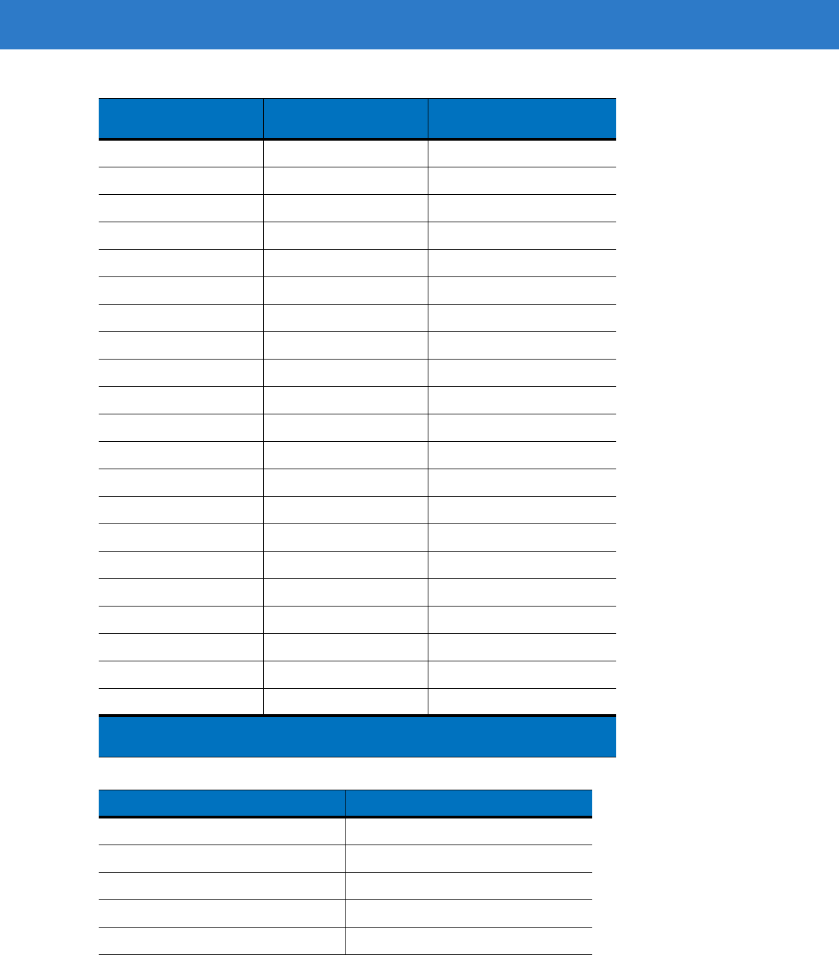
Keyboard Wedge Interface 5 - 17
1106 +J j
1107 +K k
1108 +L l
1109 +M m
1110 +N n
1111 +O o
1112 +P p
1113 +Q q
1114 +R r
1115 +S s
1116 +T t
1117 +U u
1118 +V v
1119 +W w
1120 +X x
1121 +Y y
1122 +Z z
1123 %P {
1124 %Q |
1125 %R }
1126 %S ~
Table 5-3
Keyboard Wedge ALT Key Character Set
ALT Keys Keystroke
2065 ALT A
2066 ALT B
2067 ALT C
2068 ALT D
2069 ALT E
Table 5-2
Keyboard Wedge ASCII Character Set (Continued)
ASCII Value Full ASCII Code 39
Encode Character Keystroke
1
The keystroke in bold is sent only if the “Function Key Mapping” is
enabled. Otherwise, the unbolded keystroke is sent.

5 - 18 Symbol LS4208 Product Reference Guide
2070 ALT F
2071 ALT G
2072 ALT H
2073 ALT I
2074 ALT J
2075 ALT K
2076 ALT L
2077 ALT M
2078 ALT N
2079 ALT O
2080 ALT P
2081 ALT Q
2082 ALT R
2083 ALT S
2084 ALT T
2085 ALT U
2086 ALT V
2087 ALT W
2088 ALT X
2089 ALT Y
2090 ALT Z
Table 5-4
Keyboard Wedge GIU Key Character Set
GUI Keys Keystrokes
3000 Right Control Key
3048 GUI 0
3049 GUI 1
3050 GUI 2
3051 GUI 3
3052 GUI 4
3053 GUI 5
Table 5-3
Keyboard Wedge ALT Key Character Set (Continued)
ALT Keys Keystroke

Keyboard Wedge Interface 5 - 19
3054 GUI 6
3055 GUI 7
3056 GUI 8
3057 GUI 9
3065 GUI A
3066 GUI B
3067 GUI C
3068 GUI D
3069 GUI E
3070 GUI F
3071 GUI G
3072 GUI H
3073 GUI I
3074 GUI J
3075 GUI K
3076 GUI L
3077 GUI M
3078 GUI N
3079 GUI O
3080 GUI P
3081 GUI Q
3082 GUI R
3083 GUI S
3084 GUI T
3085 GUI U
3086 GUI V
3087 GUI W
3088 GUI X
3089 GUI Y
3090 GUI Z
Table 5-4
Keyboard Wedge GIU Key Character Set (Continued)
GUI Keys Keystrokes

5 - 20 Symbol LS4208 Product Reference Guide
Table 5-5
Keyboard Wedge F Key Character Set
F Keys Keystroke
5001 F1
5002 F2
5003 F3
5004 F4
5005 F5
5006 F6
5007 F7
5008 F8
5009 F9
5010 F10
5011 F11
5012 F12
5013 F13
5014 F14
5015 F15
5016 F16
5017 F17
5018 F18
5019 F19
5020 F20
5021 F21
5022 F22
5023 F23
5024 F24

Keyboard Wedge Interface 5 - 21
Table 5-6
Keyboard Wedge Numeric Keypad Character Set
Numeric Keypad Keystroke
6042 *
6043 +
6044 undefined
6045 -
6046 .
6047 /
6048 0
6049 1
6050 2
6051 3
6052 4
6053 5
6054 6
6055 7
6056 8
6057 9
6058 Enter
6059 Num Lock

5 - 22 Symbol LS4208 Product Reference Guide
Table 5-7
Keyboard Wedge Extended Keypad Character Set
Extended Keypad Keystroke
7001 Break
7002 Delete
7003 Pg Up
7004 End
7005 Pg Dn
7006 Pause
7007 Scroll Lock
7008 Backspace
7009 Tab
7010 Print Screen
7011 Insert
7012 Home
7013 Enter
7014 Escape
7015 Up Arrow
7016 Dn Arrow
7017 Left Arrow
7018 Right Arrow

Chapter 6 RS-232 Interface
Introduction
This chapter describes how to set up the scanner with an RS-232 host. The RS-232 interface is used to connect
the scanner to point-of-sale devices, host computers, or other devices with an available RS-232 port (e.g., com
port).
If the host is not listed in Table 6-2, refer to the documentation for the host device to set communication parameters
to match the host.
Throughout the programming bar code menus, default values are indicated with asterisks (*).
NOTE The scanner uses TTL RS-232 signal levels, which interface with most system architectures. For system
architectures requiring RS-232C signal levels, Symbol offers different cables providing TTL-to-RS-232C
conversion. Contact Motorola Enterprise Mobility Support for more information.
*Baud Rate 57,600 Feature/Option
* Indicates Default
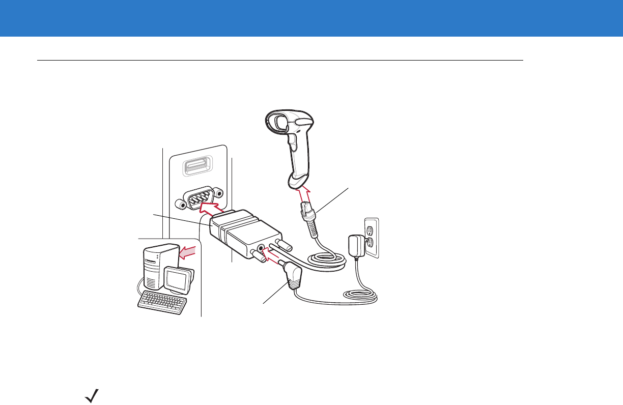
6 - 2 Symbol LS4208 Product Reference Guide
Connecting an RS-232 Interface
This connection is made directly from the scanner to the host computer.
Figure 6-1
RS-232 Direct Connection
1. Attach the modular connector of the RS-232 interface cable to the cable interface port on the scanner (see
Installing the Interface Cable on page 1-3).
2. Connect the other end of the RS-232 interface cable to the serial port on the host.
3. Connect the power supply to the serial connector end of the RS-232 interface cable. Plug the power supply
into an appropriate outlet.
4. Select the RS-232 host type by scanning the appropriate bar code from RS-232 Host Types on page 6-6.
5. To modify any other parameter options, scan the appropriate bar codes in this chapter.
Serial Port
Connector to Host
Interface Cable
Power Supply Cable
NOTE Interface cables vary depending on configuration. The connectors illustrated in Figure 6-1 are examples
only. The connectors may be different than those illustrated, but the steps to connect the scanner remain
the same.
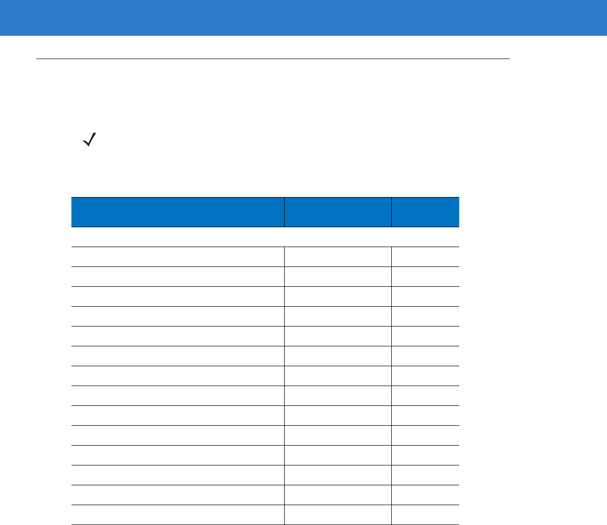
RS-232 Interface 6 - 3
RS-232 Parameter Defaults
Table 6-1 lists the defaults for RS-232 host parameters. If any option needs to be changed, scan the appropriate
bar code(s) provided in the Parameter Descriptions section beginning on page 6-4.
NOTE See Appendix A, Standard Default Parameters for all user preferences, hosts, symbologies, and
miscellaneous default parameters.
Table 6-1
RS-232 Host Default Table
Parameter Default Page
Number
RS-232 Host Parameters
RS-232 Host Types Standard 6-6
Baud Rate 9600 6-7
Parity Type None 6-8
Stop Bit Select 1 Stop Bit 6-9
Data Bits (ASCII Format) 8-Bit 6-9
Check Receive Errors Enable 6-10
Hardware Handshaking None 6-10
Software Handshaking None 6-12
Host Serial Response Time-out 2 Sec 6-14
RTS Line State Low RTS 6-15
Beep on <BEL> Disable 6-15
Intercharacter Delay 0 msec 6-16
Nixdorf Beep/LED Options Normal Operation 6-17
Ignore Unknown Characters Send Bar Code 6-17
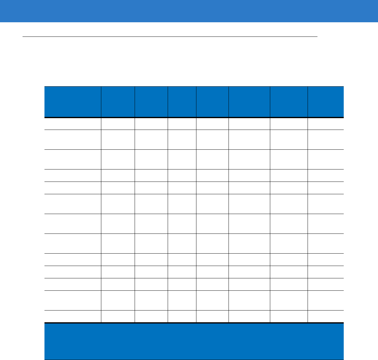
6 - 4 Symbol LS4208 Product Reference Guide
RS-232 Host Parameters
Various RS-232 hosts are set up with their own parameter default settings (Table 6-2). Selecting the ICL, Fujitsu,
Wincor-Nixdorf Mode A, Wincor-Nixdorf Mode B, Olivetti, Omron, or terminal sets the defaults listed below.
Table 6-2
Terminal Specific RS-232
Parameter Standard
(Default) ICL Fujitsu
Wincor-
Nixdorf
Mode A
Wincor-
Nixdorf
Mode B/
OPOS
Olivetti Omron
Transmit Code ID No Yes Yes Yes Yes Yes Yes
Data Transmission
Format Data as is Data/
Suffix Data/
Suffix Data/
Suffix Data/Suffix Prefix/Data/
Suffix Data/Suffix
Suffix CR/LF
(7013) CR
(1013) CR
(1013) CR
(1013) CR (1013) ETX (1002) CR (1013)
Baud Rate 9600 9600 9600 9600 9600 9600 9600
Parity None Even None Odd Odd Even None
Hardware
Handshaking None RTS/CTS
Option 3 None RTS/CTS
Option 3 RTS/CTS
Option 3 None None
Software
Handshaking None None None None None Ack/Nak None
Serial Response
Time-out 2 Sec. 9.9 Sec. 2 Sec. 9.9 Sec. 9.9 Sec. 9.9 Sec. 9.9 Sec.
Stop Bit Select One One One One One One One
ASCII Format 8-Bit 8-Bit 8-Bit 8-Bit 8-Bit 7-Bit 8-Bit
Beep On <BEL> Disable Disable Disable Disable Disable Disable Disable
RTS Line State Low High Low Low Low = No
data to send Low High
Prefix None None None None None STX (1003) None
*In the Nixdorf Mode B, if CTS is Low, scanning is disabled. When CTS is High, the user can scan
bar codes.
**If Nixdorf Mode B is scanned without the scanner connected to the proper host, it may appear
unable to scan. If this happens, scan a different RS-232 host type within 5 seconds of cycling
power to the scanner.
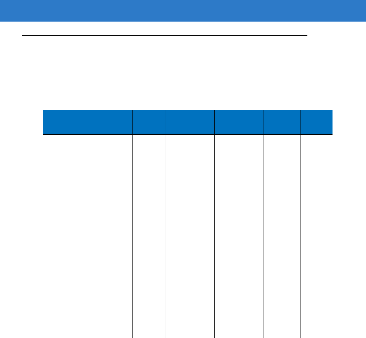
RS-232 Interface 6 - 5
RS-232 Host Parameters (continued)
Selecting the ICL, Fujitsu, Wincor-Nixdorf Mode A, Wincor-Nixdorf Mode B, OPOS terminal enables the
transmission of code ID characters listed in Table 6-3 below. These code ID characters are not programmable and
are separate from the Transmit Code ID feature. The Transmit Code ID feature should not be enabled for these
terminals.
Table 6-3
Terminal Specific Code ID Characters
Code Type ICL Fujitsu
Wincor-
Nixdorf
Mode A
Wincor-
Nixdorf
Mode B/OPOS
Olivetti Omron
UPC-A A A A A A A
UPC-E E E C C C E
EAN-8/JAN-8 FF FF B B B FF
EAN-13/JAN-13 F F A A A F
Code 39 C <len> None M M M <len> C <len>
Codabar N <len> None N N N <len> N <len>
Code 128 L <len> None K K K <len> L <len>
I 2 of 5 I <len> None I I I <len> I <len>
Code 93 None None L L L <len> None
D 2 of 5 H <len> None H H H <len> H <len>
GS1-128 L <len> None P P P <len> L <len>
MSI None None O O O <len> None
Bookland EAN F F A A A F
Trioptic None None None None None None
Code 11 None None None None None None
IATA H<len> None H H None None
Code 32 None None None None None None
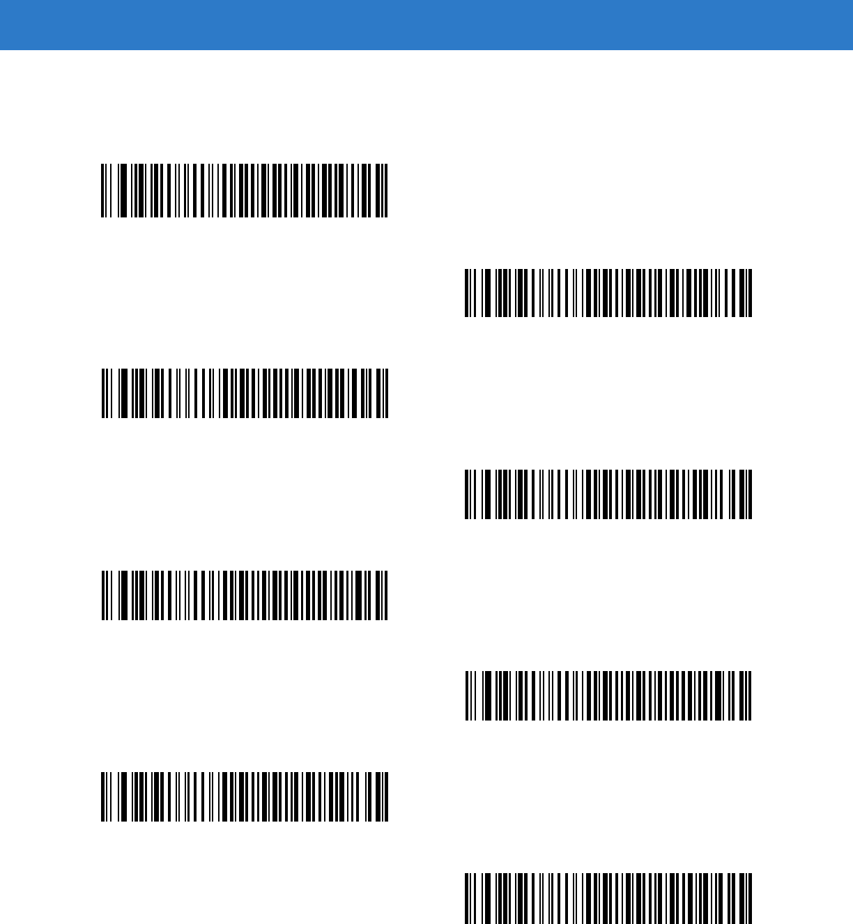
6 - 6 Symbol LS4208 Product Reference Guide
RS-232 Host Types
To select an RS-232 host interface, scan one of the following bar codes.
*Standard RS-232
ICL RS-232
Wincor-Nixdorf RS-232 Mode A
Wincor-Nixdorf RS-232 Mode B
Olivetti ORS4500
Omron
OPOS/JPOS
Fujitsu RS-232
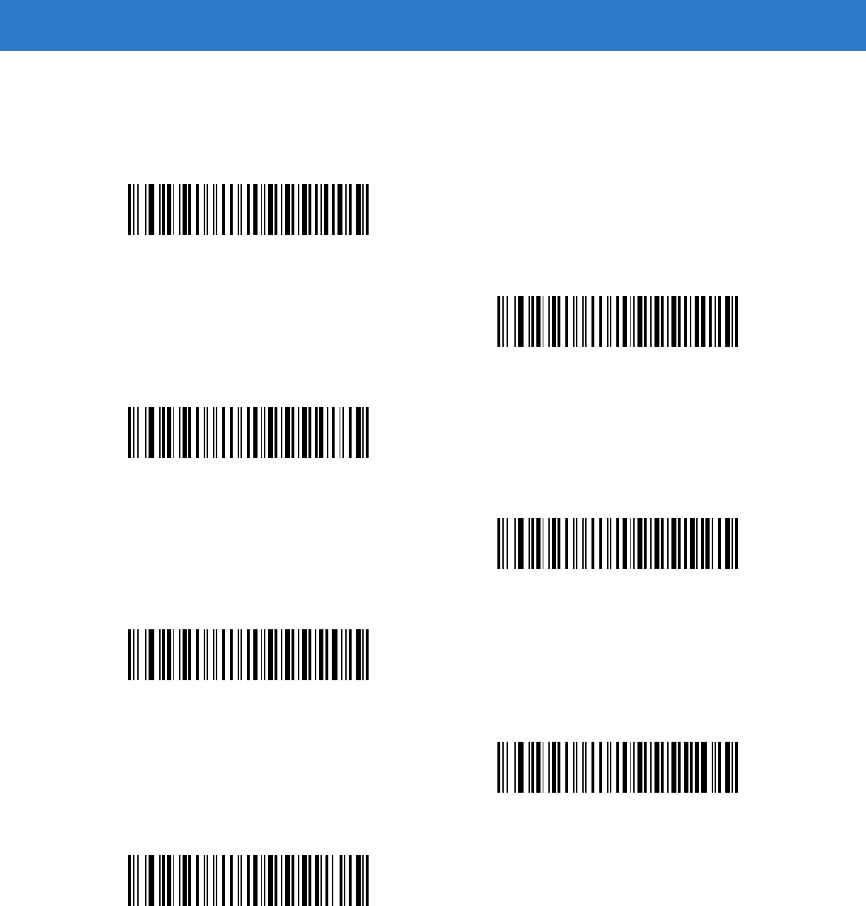
RS-232 Interface 6 - 7
Baud Rate
Baud rate is the number of bits of data transmitted per second. Set the scanner's baud rate to match the baud rate
setting of the host device. Otherwise, data may not reach the host device or may reach it in distorted form.
Baud Rate 600
Baud Rate 1200
Baud Rate 2400
Baud Rate 4800
*Baud Rate 9600
Baud Rate 19,200
Baud Rate 38,400
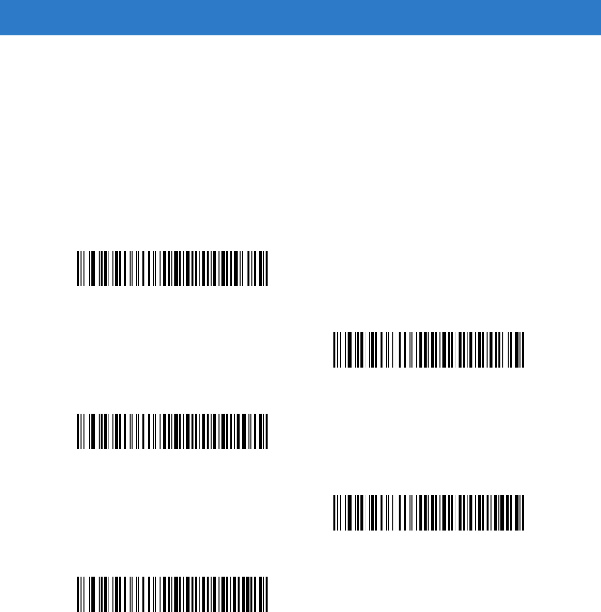
6 - 8 Symbol LS4208 Product Reference Guide
Parity
A parity check bit is the most significant bit of each ASCII coded character. Select the parity type according to host
device requirements.
•
Select Odd parity and the parity bit value is set to 0 or 1, based on data, to ensure that an odd number of 1
bits are contained in the coded character.
•
Select Even parity and the parity bit value is set to 0 or 1, based on data, to ensure that an even number of 1
bits are contained in the coded character.
•
Select Mark parity and the parity bit is always 1.
•
Select Space parity and the parity bit is always 0.
•
Select None when no parity bit is required.
Odd
Even
Mark
Space
*None

RS-232 Interface 6 - 9
Stop Bit Select
The stop bit(s) at the end of each transmitted character marks the end of transmission of one character and
prepares the receiving device for the next character in the serial data stream. The number of stop bits selected
(one or two) depends on the number the receiving terminal is programmed to accommodate. Set the number of
stop bits to match host device requirements.
Data Bits (ASCII Format)
This parameter allows the scanner to interface with devices requiring a 7-bit or 8-bit ASCII protocol.
*1 Stop Bit
2 Stop Bits
7-Bit
*8-Bit

6 - 10 Symbol LS4208 Product Reference Guide
Check Receive Errors
Select whether or not the parity, framing, and overrun of received characters are checked. The parity value of
received characters is verified against the parity parameter selected above.
Hardware Handshaking
The data interface consists of an RS-232 port designed to operate either with or without the hardware handshaking
lines, Request to Send (RTS), and Clear to Send (CTS).
If Standard RTS/CTS handshaking is not selected, scan data is transmitted as it becomes available. If Standard
RTS/CTS handshaking is selected, scan data is transmitted according to the following sequence:
•
The scanner reads the CTS line for activity. If CTS is asserted, the scanner waits up to Host Serial Response
Time-out for the host to de-assert the CTS line. If, after Host Serial Response Time-out, the CTS line is still
asserted, the scanner sounds a transmit error, and any scanned data is lost.
•
When the CTS line is de-asserted, the scanner asserts the RTS line and waits up to Host Serial Response
Time-out for the host to assert CTS. When the host asserts CTS, data is transmitted. If, after Host Serial
Response Time-out, the CTS line is not asserted, the scanner sounds a transmit error, and discards the data.
•
When data transmission is complete, the scanner de-asserts RTS 10 msec after sending the last character.
•
The host should respond by negating CTS. The scanner checks for a de-asserted CTS upon the next
transmission of data.
During the transmission of data, the CTS line should be asserted. If CTS is de-asserted for more than 50 ms
between characters, the transmission is aborted, the scanner sounds a transmission error, and the data is
discarded.
If the above communication sequence fails, the scanner issues an error indication. In this case, the data is lost and
must be rescanned.
If Hardware Handshaking and Software Handshaking are both enabled, Hardware Handshaking takes
precedence.
*Check For Received Errors
(Enable)
Do Not Check For Received Errors
(Disable)
NOTE The DTR signal is jumpered to the active state.
RS-232 Interface 6 - 11
•
None: Scan the bar code below if no Hardware Handshaking is desired.
•
Standard RTS/CTS: Scan the bar code below to select Standard RTS/CTS Hardware Handshaking.
•
RTS/CTS Option 1: When RTS/CTS Option 1 is selected, the scanner asserts RTS before transmitting and
ignores the state of CTS. The scanner de-asserts RTS when the transmission is complete.
•
RTS/CTS Option 2: When Option 2 is selected, RTS is always high or low (user-programmed logic level).
However, the scanner waits for CTS to be asserted before transmitting data. If CTS is not asserted within
Host Serial Response Time-out, the scanner issues an error indication and discards the data.
•
RTS/CTS Option 3: When Option 3 is selected, the scanner asserts RTS prior to any data transmission,
regardless of the state of CTS. The scanner waits up to Host Serial Response Time-out for CTS to be
asserted. If CTS is not asserted during this time, the scanner issues an error indication and discards the
data. The scanner de-asserts RTS when transmission is complete.
*None
Standard RTS/CTS
RTS/CTS Option 1
RTS/CTS Option 2
RTS/CTS Option 3

6 - 12 Symbol LS4208 Product Reference Guide
Software Handshaking
This parameter offers control of the data transmission process in addition to, or instead of, that offered by hardware
handshaking. There are five options.
If Software Handshaking and Hardware Handshaking are both enabled, Hardware Handshaking takes
precedence.
•
None: When this option is selected, data is transmitted immediately. No response is expected from host.
•
ACK/NAK: When this option is selected, after transmitting data, the scanner expects either an ACK or NAK
response from the host. When a NAK is received, the scanner transmits the same data again and waits for
either an ACK or NAK. After three unsuccessful attempts to send data when NAKs are received, the scanner
issues an error indication and discards the data.
The scanner waits up to the programmable Host Serial Response Time-out to receive an ACK or NAK. If the
scanner does not get a response in this time, it issues an error indication and discards the data. There are no
retries when a time-out occurs.
•
ENQ: When this option is selected, the scanner waits for an ENQ character from the host before transmitting
data. If an ENQ is not received within the Host Serial Response Time-out, the scanner issues an error
indication and discards the data. The host must transmit an ENQ character at least every Host Serial
Response Time-out to prevent transmission errors.
•
ACK/NAK with ENQ: This combines the two previous options. For re-transmissions of data, due to a NAK
from the host, an additional ENQ is not required.
•
XON/XOFF: An XOFF character turns the scanner transmission off until the scanner receives an XON
character. There are two situations for XON/XOFF:
•XOFF is received before the scanner has data to send. When the scanner has data to send, it waits up to
Host Serial Response Time-out for an XON character before transmission. If the XON is not received
within this time, the scanner issues an error indication and discards the data.
•XOFF is received during a transmission. Data transmission then stops after sending the current byte.
When the scanner receives an XON character, it sends the rest of the data message. The scanner waits
up to 30 seconds for the XON.
RS-232 Interface 6 - 13
Software Handshaking (continued)
*None
ACK/NAK
ENQ
ACK/NAK with ENQ
XON/XOFF
6 - 14 Symbol LS4208 Product Reference Guide
Host Serial Response Time-out
This parameter specifies how long the scanner waits for an ACK, NAK, ENQ, XON, or CTS before determining that
a transmission error occurred.
*Minimum: 2 Sec
Low: 2.5 Sec
Medium: 5 Sec
High: 7.5 Sec
Maximum: 9.9 Sec
RS-232 Interface 6 - 15
RTS Line State
This parameter sets the idle state of the Serial Host RTS line. Scan a bar code below to select Low RTS or High
RTS line state.
Beep on <BEL>
When this parameter is enabled, the scanner issues a beep when a <BEL> character is detected on the RS-232
serial line. <BEL> is issued to gain a user's attention to an illegal entry or other important event.
*Host: Low RTS
Host: High RTS
Beep On <BEL> Character
(Enable)
*Do Not Beep On <BEL> Character
(Disable)
6 - 16 Symbol LS4208 Product Reference Guide
Intercharacter Delay
This parameter specifies the intercharacter delay inserted between character transmissions.
*Minimum: 0 msec
Low: 25 msec
Medium: 50 msec
High: 75 msec
Maximum: 99 msec
RS-232 Interface 6 - 17
Nixdorf Beep/LED Options
When Nixdorf Mode B is selected, this indicates when the scanner should beep and turn on its LED after a decode.
Ignore Unknown Characters
Unknown characters are characters the host does not recognize. When Send Bar Codes with Unknown
Characters is selected, all bar code data is sent except for unknown characters, and no error beeps sound on the
scanner. When Do Not Send Bar Codes With Unknown Characters is selected, bar code data is sent up to the
first unknown character and then an error beep sounds on the scanner.
*Normal Operation
(Beep/LED immediately after decode)
Beep/LED After Transmission
Beep/LED After CTS Pulse
*Send Bar Code with Unknown Characters
Do Not Send Bar Codes with Unknown Characters

6 - 18 Symbol LS4208 Product Reference Guide
ASCII Character Set for RS-232
The values in Table 6-4 can be assigned as prefixes or suffixes for ASCII character data transmission.
Table 6-4
ASCII Character Set for RS-232
ASCII Value Full ASCII
Code 39 Encode Character ASCII Character
1000 %U NUL
1001 $A SOH
1002 $B STX
1003 $C ETX
1004 $D EOT
1005 $E ENQ
1006 $F ACK
1007 $G BELL
1008 $H BCKSPC
1009 $I HORIZ TAB
1010 $J LF/NW LN
1011 $K VT
1012 $L FF
1013 $M CR/ENTER
1014 $N SO
1015 $O SI
1016 $P DLE
1017 $Q DC1/XON
1018 $R DC2
1019 $S DC3/XOFF
1020 $T DC4
1021 $U NAK
1022 $V SYN
1023 $W ETB
1024 $X CAN
1025 $Y EM
1026 $Z SUB

RS-232 Interface 6 - 19
1027 %A ESC
1028 %B FS
1029 %C GS
1030 %D RS
1031 %E US
1032 Space Space
1033 /A !
1034 /B "
1035 /C #
1036 /D $
1037 /E %
1038 /F &
1039 /G ‘
1040 /H (
1041 /I )
1042 /J *
1043 /K +
1044 /L ,
1045 - -
1046 . .
1047 /O /
1048 0 0
1049 1 1
1050 2 2
1051 3 3
1052 4 4
1053 5 5
1054 6 6
1057 7 7
1056 8 8
Table 6-4
ASCII Character Set for RS-232 (Continued)
ASCII Value Full ASCII
Code 39 Encode Character ASCII Character

6 - 20 Symbol LS4208 Product Reference Guide
1057 9 9
1058 /Z :
1059 %F ;
1060 %G <
1061 %H =
1062 %I >
1063 %J ?
1064 %V @
1065 A A
1066 B B
1067 C C
1068 D D
1069 E E
1070 F F
1071 G G
1072 H H
1073 I I
1074 J J
1075 K K
1076 L L
1077 M M
1078 N N
1079 O O
1080 P P
1081 Q Q
1082 R R
1083 S S
1084 T T
1085 U U
1086 V V
Table 6-4
ASCII Character Set for RS-232 (Continued)
ASCII Value Full ASCII
Code 39 Encode Character ASCII Character

RS-232 Interface 6 - 21
1087 W W
1088 X X
1089 Y Y
1090 Z Z
1091 %K [
1092 %L \
1093 %M ]
1094 %N ^
1095 %O _
1096 %W `
1097 +A a
1098 +B b
1099 +C c
1100 +D d
1101 +E e
1102 +F f
1103 +G g
1104 +H h
1105 +I i
1106 +J j
1107 +K k
1108 +L l
1109 +M m
1110 +N n
1111 +O o
1112 +P p
1113 +Q q
1114 +R r
1115 +S s
1116 +T t
Table 6-4
ASCII Character Set for RS-232 (Continued)
ASCII Value Full ASCII
Code 39 Encode Character ASCII Character

6 - 22 Symbol LS4208 Product Reference Guide
1117 +U u
1118 +V v
1119 +W w
1120 +X x
1121 +Y y
1122 +Z z
1123 %P {
1124 %Q |
1125 %R }
1126 %S ~
1127 Undefined
7013 ENTER
Table 6-4
ASCII Character Set for RS-232 (Continued)
ASCII Value Full ASCII
Code 39 Encode Character ASCII Character

Chapter 7 USB Interface
Introduction
This chapter covers the connection and setup of the scanner to a USB host. The scanner attaches directly to a
USB host, or a powered USB hub, and is powered by it. No additional power supply is required.
Throughout the programming bar code menus, default values are indicated with asterisks (*).
*North American Standard USB Keyboard Feature/Option
* Indicates Default
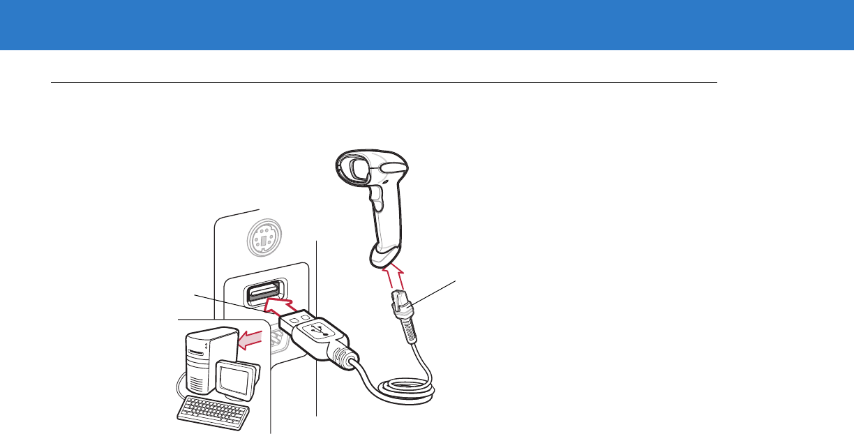
7 - 2 Symbol LS4208 Product Reference Guide
Connecting a USB Interface
Figure 7-1
USB Connection
The scanner connects with USB capable hosts including:
•
Desktop PCs and Notebooks
•
Apple™ iMac, G4, iBooks (North America only)
•
IBM SurePOS terminals
•
Sun, IBM, and other network computers that support more than one keyboard.
The following operating systems support the scanner through USB:
•
Windows 98, 2000, ME, XP
•
MacOS 8.5 and above
•
IBM 4690 OS.
The scanner will also interface with other USB hosts which support USB Human Interface Devices (HID). For more
information on USB technology, hosts, and peripheral devices, visit www.symbol.com/usb.
Interface cable
USB Series A
Connector

USB Interface 7 - 3
To set up the scanner:
1. Attach the modular connector of the USB interface cable to the cable interface port on the scanner (see
Installing the Interface Cable on page 1-3).
2. Plug the series A connector in the USB host or hub, or plug the Plus Power connector in an available port of
the IBM SurePOS terminal.
3. Select the USB device type by scanning the appropriate bar code from USB Device Type on page 7-5.
4. On first installation when using Windows, the software prompts to select or install the Human Interface Device
driver. To install this driver, provided by Windows, click Next through all the choices and click Finished on the
last choice. The scanner powers up during this installation.
5. To modify any other parameter options, scan the appropriate bar codes in this chapter.
If problems occur with the system, see Troubleshooting on page 3-2.
NOTE Interface cables vary depending on configuration. The connectors illustrated in Figure 7-1 are examples
only. The connectors may be different than those illustrated, but the steps to connect the scanner are the
same.
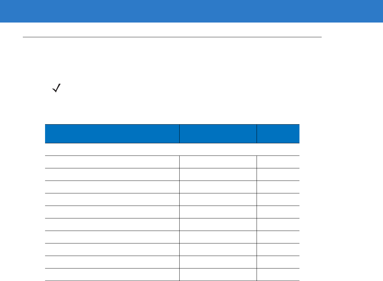
7 - 4 Symbol LS4208 Product Reference Guide
USB Parameter Defaults
Table 7-1 lists the defaults for USB host parameters. If any option needs to be changed, scan the appropriate bar
code(s) provided in the Parameter Descriptions section beginning on page 7-5.
NOTE See Appendix A, Standard Default Parameters for all user preferences, hosts, symbologies, and
miscellaneous default parameters.
Table 7-1
USB Host Default Table
Parameter Default Page
Number
USB Host Parameters
USB Device Type HID Keyboard Emulation 7-5
USB Country Keyboard Types (Country Codes) North American 7-6
USB Keystroke Delay No Delay 7-8
USB CAPS Lock Override Disable 7-8
USB Ignore Unknown Characters Send 7-9
Emulate Keypad Disable 7-9
USB FN1 Substitution Disable 7-10
Function Key Mapping Disable 7-10
Simulated Caps Lock Disable 7-11
Convert Case No Case Conversion 7-11
USB Interface 7 - 5
USB Host Parameters
USB Device Type
Select the desired USB device type.
NOTE When changing USB Device Types, the scanner automatically restarts. The scanner issues the standard
startup beep sequences.
*HID Keyboard Emulation
IBM Table Top USB
IBM Hand-Held USB
USB OPOS Handheld
Simple COM Port Emulation
7 - 6 Symbol LS4208 Product Reference Guide
USB Country Keyboard Types (Country Codes)
Scan the bar code corresponding to the keyboard type. This setting applies only to the USB HID Keyboard
Emulation device.
NOTE When changing USB country keyboard types the scanner automatically resets. The scanner
issues the standard startup beep sequences.
*North American Standard USB Keyboard
German Windows
French Windows
French Canadian Windows 95/98
French Canadian Windows 2000/XP
Spanish Windows

USB Interface 7 - 7
USB Country Keyboard Types (Country Codes continued)
Italian Windows
Swedish Windows
UK English Windows
Japanese Windows (ASCII)
Portuguese-Brazilian Windows
7 - 8 Symbol LS4208 Product Reference Guide
USB Keystroke Delay
This parameter sets the delay, in milliseconds, between emulated keystrokes. Scan a bar code below to increase
the delay when hosts require a slower transmission of data.
USB CAPS Lock Override
This option applies only to the HID Keyboard Emulation device. When enabled, the case of the data is preserved
regardless of the state of the caps lock key. This setting is always enabled for the “Japanese, Windows (ASCII)”
keyboard type and can not be disabled.
*No Delay
Medium Delay (20 msec)
Long Delay (40 msec)
Override Caps Lock Key
(Enable)
*Do Not Override Caps Lock Key
(Disable)
USB Interface 7 - 9
USB Ignore Unknown Characters
This option applies only to the HID Keyboard Emulation device and IBM device. Unknown characters are
characters the host does not recognize. When Send Bar Codes With Unknown Characters is selected, all bar
code data is sent except for unknown characters, and no error beeps sound. When Do Not Send Bar Codes With
Unknown Characters is selected, bar code data is sent up to the first unknown character, then the scanner issues
an error beep.
Emulate Keypad
When enabled, all characters are sent as ASCII sequences over the numeric keypad. For example ASCII A would
be sent as “ALT make” 0 6 5 “ALT Break.”
*Send Bar Codes with Unknown Characters
Do Not Send Bar Codes with Unknown Characters
*Disable Keypad Emulation
Enable Keypad Emulation
7 - 10 Symbol LS4208 Product Reference Guide
USB Keyboard FN 1 Substitution
This option applies only to the USB HID Keyboard Emulation device. When enabled, this allows replacement of
any FN 1 characters in a GS1-128 bar code with a Key Category and value chosen by the user (see FN1
Substitution Values on page 13-6 to set the Key Category and Key Value).
Function Key Mapping
ASCII values under 32 are normally sent as a control-key sequences (see Table 7-2 on page 7-12). When this
parameter is enabled, the keys in bold are sent in place of the standard key mapping. Table entries that do not
have a bold entry remain the same whether or not this parameter is enabled.
Enable FN1 Substitution
*Disable FN1 Substitution
*Disable Function Key Mapping
Enable Function Key Mapping
USB Interface 7 - 11
Simulated Caps Lock
When enabled, the scanner will invert upper and lower case characters on the scanner bar code as if the Caps
Lock state is enabled on the keyboard. This inversion is done regardless of the current state of the keyboard’s
Caps Lock state.
Convert Case
When enabled, the scanner will convert all bar code data to the selected case.
*Disable Simulated Caps Lock
Enable Simulated Caps Lock
*No Case Conversion
Convert All to Upper Case
Convert All to Lower Case
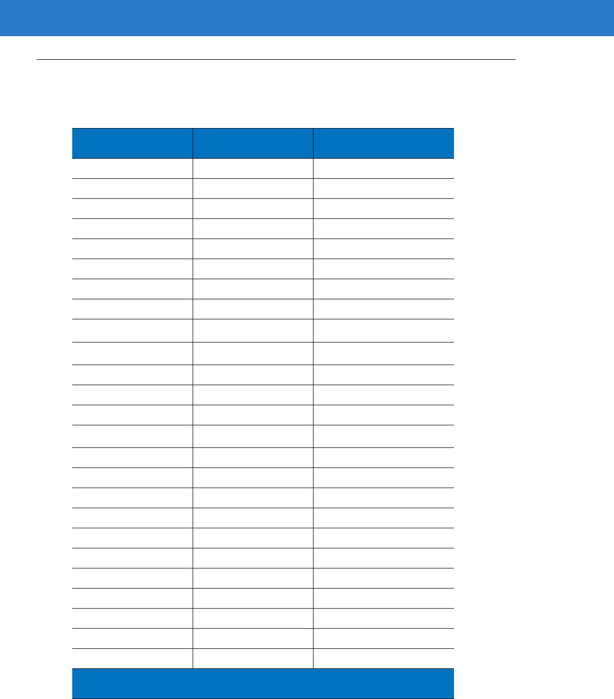
7 - 12 Symbol LS4208 Product Reference Guide
ASCII Character Set for USB
Table 7-2
ASCII Character Set for USB
ASCII Value Full ASCII Code 39
Encode Character Keystroke
1000 %U CTRL 2
1001 $A CTRL A
1002 $B CTRL B
1003 $C CTRL C
1004 $D CTRL D
1005 $E CTRL E
1006 $F CTRL F
1007 $G CTRL G
1008 $H CTRL H/
BACKSPACE
1
1009 $I CTRL I/
HORIZONTAL TAB
1
1010 $J CTRL J
1011 $K CTRL K
1012 $L CTRL L
1013 $M CTRL M/
ENTER
1
1014 $N CTRL N
1015 $O CTRL O
1016 $P CTRL P
1017 $Q CTRL Q
1018 $R CTRL R
1019 $S CTRL S
1020 $T CTRL T
1021 $U CTRL U
1022 $V CTRL V
1023 $W CTRL W
1024 $X CTRL X
1
The keystroke in bold is sent only if the “Function Key Mapping” is enabled.
Otherwise, the unbolded keystroke is sent.

USB Interface 7 - 13
1025 $Y CTRL Y
1026 $Z CTRL Z
1027 %A CTRL [/
ESC
1
1028 %B CTRL \
1029 %C CTRL ]
1030 %D CTRL 6
1031 %E CTRL -
1032 Space Space
1033 /A !
1034 /B “
1035 /C #
1036 /D $
1037 /E %
1038 /F &
1039 /G ‘
1040 /H (
1041 /I )
1042 /J *
1043 /K +
1044 /L ,
1045 - -
1046 . .
1047 /O /
1048 0 0
1049 1 1
1050 2 2
1051 3 3
1052 4 4
Table 7-2
ASCII Character Set for USB (Continued)
ASCII Value Full ASCII Code 39
Encode Character Keystroke
1
The keystroke in bold is sent only if the “Function Key Mapping” is enabled.
Otherwise, the unbolded keystroke is sent.

7 - 14 Symbol LS4208 Product Reference Guide
1053 5 5
1054 6 6
1055 7 7
1056 8 8
1057 9 9
1058 /Z :
1059 %F ;
1060 %G <
1061 %H =
1062 %I >
1063 %J ?
1064 %V @
1065 A A
1066 B B
1067 C C
1068 D D
1069 E E
1070 F F
1071 G G
1072 H H
1073 I I
1074 J J
1075 K K
1076 L L
1077 M M
1078 N N
1079 O O
1080 P P
Table 7-2
ASCII Character Set for USB (Continued)
ASCII Value Full ASCII Code 39
Encode Character Keystroke
1
The keystroke in bold is sent only if the “Function Key Mapping” is enabled.
Otherwise, the unbolded keystroke is sent.

USB Interface 7 - 15
1081 Q Q
1082 R R
1083 S S
1084 T T
1085 U U
1086 V V
1087 W W
1088 X X
1089 Y Y
1090 Z Z
1091 %K [
1092 %L \
1093 %M ]
1094 %N ^
1095 %O _
1096 %W `
1097 +A a
1098 +B b
1099 +C c
1100 +D d
1101 +E e
1102 +F f
1103 +G g
1104 +H h
1105 +I i
1106 +J j
1107 +K k
1108 +L l
Table 7-2
ASCII Character Set for USB (Continued)
ASCII Value Full ASCII Code 39
Encode Character Keystroke
1
The keystroke in bold is sent only if the “Function Key Mapping” is enabled.
Otherwise, the unbolded keystroke is sent.

7 - 16 Symbol LS4208 Product Reference Guide
1109 +M m
1110 +N n
1111 +O o
1112 +P p
1113 +Q q
1114 +R r
1115 +S s
1116 +T t
1117 +U u
1118 +V v
1119 +W w
1120 +X x
1121 +Y y
1122 +Z z
1123 %P {
1124 %Q |
1125 %R }
1126 %S ~
Table 7-2
ASCII Character Set for USB (Continued)
ASCII Value Full ASCII Code 39
Encode Character Keystroke
1
The keystroke in bold is sent only if the “Function Key Mapping” is enabled.
Otherwise, the unbolded keystroke is sent.

USB Interface 7 - 17
Table 7-3
USB ALT Key Character Set
ALT Keys Keystroke
2064 ALT 2
2065 ALT A
2066 ALT B
2067 ALT C
2068 ALT D
2069 ALT E
2070 ALT F
2071 ALT G
2072 ALT H
2073 ALT I
2074 ALT J
2075 ALT K
2076 ALT L
2077 ALT M
2078 ALT N
2079 ALT O
2080 ALT P
2081 ALT Q
2082 ALT R
2083 ALT S
2084 ALT T
2085 ALT U
2086 ALT V
2087 ALT W
2088 ALT X
2089 ALT Y
2090 ALT Z

7 - 18 Symbol LS4208 Product Reference Guide
Table 7-4
USB GUI Key Character Set
GUI Key Keystroke
3000 Right Control Key
3048 GUI 0
3049 GUI 1
3050 GUI 2
3051 GUI 3
3052 GUI 4
3053 GUI 5
3054 GUI 6
3055 GUI 7
3056 GUI 8
3057 GUI 9
3065 GUI A
3066 GUI B
3067 GUI C
3068 GUI D
3069 GUI E
3070 GUI F
3071 GUI G
3072 GUI H
3073 GUI I
3074 GUI J
3075 GUI K
3076 GUI L
3077 GUI M
3078 GUI N
3079 GUI O
3080 GUI P
Note:
GUI Shift Keys - The Apple
™
iMac keyboard has an apple key on either side of the
space bar. Windows-based systems have a GUI key to the left of the left ALT key, and to the
right of the right ALT key.
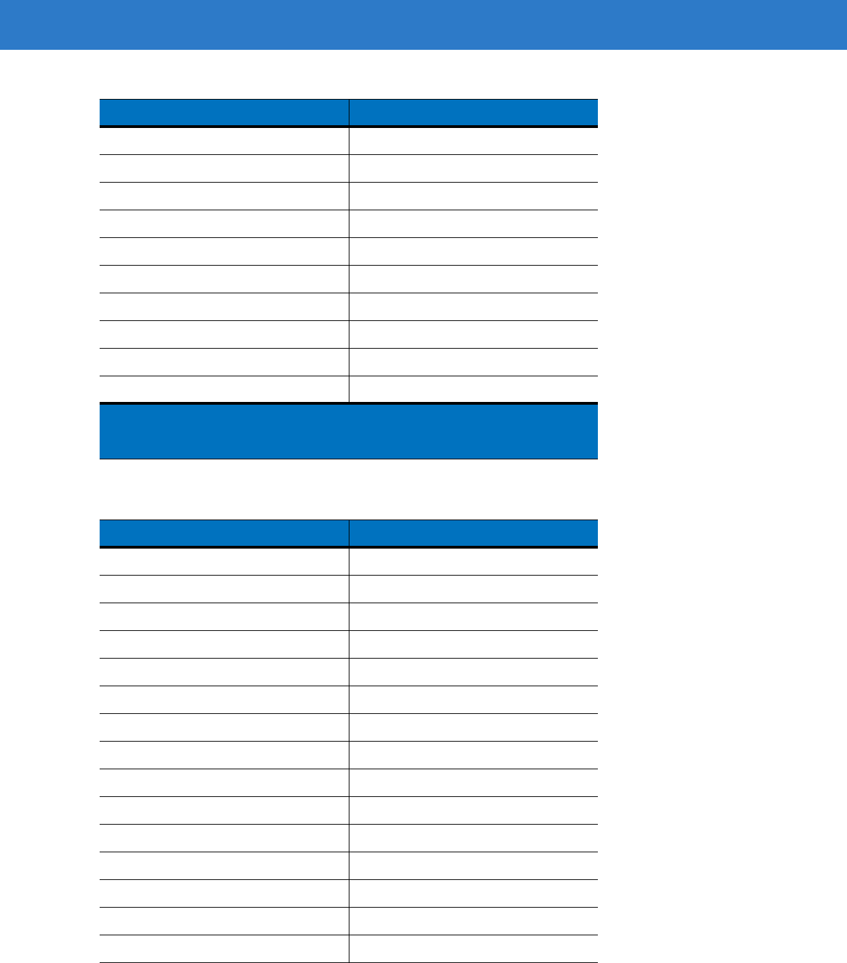
USB Interface 7 - 19
3081 GUI Q
3082 GUI R
3083 GUI S
3084 GUI T
3085 GUI U
3086 GUI V
3087 GUI W
3088 GUI X
3089 GUI Y
3090 GUI Z
Table 7-5
USB F Key Character Set
F Keys Keystroke
5001 F1
5002 F2
5003 F3
5004 F4
5005 F5
5006 F6
5007 F7
5008 F8
5009 F9
5010 F10
5011 F11
5012 F12
5013 F13
5014 F14
5015 F15
Table 7-4
USB GUI Key Character Set (Continued)
GUI Key Keystroke
Note:
GUI Shift Keys - The Apple
™
iMac keyboard has an apple key on either side of the
space bar. Windows-based systems have a GUI key to the left of the left ALT key, and to the
right of the right ALT key.
7 - 20 Symbol LS4208 Product Reference Guide
5016 F16
5017 F17
5018 F18
5019 F19
5020 F20
5021 F21
5022 F22
5023 F23
5024 F24
Table 7-6
USB Numeric Keypad Character Set
Numeric Keypad Keystroke
6042 *
6043 +
6044 undefined
6045 -
6046 .
6047 /
6048 0
6049 1
6050 2
6051 3
6052 4
6053 5
6054 6
6055 7
6056 8
6057 9
6058 Enter
6059 Num Lock
Table 7-5
USB F Key Character Set (Continued)
F Keys Keystroke

USB Interface 7 - 21
Table 7-7
USB Extended Keypad Character Set
Extended Keypad Keystroke
7001 Break
7002 Delete
7003 PgUp
7004 End
7005 Pg Dn
7006 Pause
7007 Scroll Lock
7008 Backspace
7009 Tab
7010 Print Screen
7011 Insert
7012 Home
7013 Enter
7014 Escape
7015 Up Arrow
7016 Down Arrow
7017 Left Arrow
7018 Right Arrow

7 - 22 Symbol LS4208 Product Reference Guide

Chapter 8 IBM Interface
Introduction
This chapter describes how to set up the scanner with an IBM 468X/469X host.
Throughout the programming bar code menus, default values are indicated with asterisks (*).
*Disable Convert to Code 39 Feature/Option
* Indicates Default
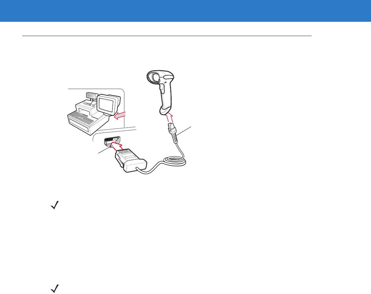
8 - 2 Symbol LS4208 Product Reference Guide
Connecting to an IBM 468X/469X Host
This connection is made directly from the scanner to the host interface.
Figure 8-1
IBM Direct Connection
1. Attach the modular connector of the IBM 46XX interface cable to the cable interface port on the scanner (see
Installing the Interface Cable on page 1-3).
2. Connect the other end of the IBM 46XX interface cable to the appropriate port on the host (typically Port 9).
3. Select the port address by scanning the appropriate bar code from Port Address on page 8-4.
4. To modify any other parameter options, scan the appropriate bar codes in this chapter.
Host Port Connector
Interface cable
NOTE Interface cables vary depending on configuration. The connectors illustrated in Figure 8-1 are examples
only. The connectors may be different than those illustrated, but the steps to connect the scanner are the
same.
NOTE The only required configuration is the port number. Other scanner parameters are typically controlled by
the IBM system.
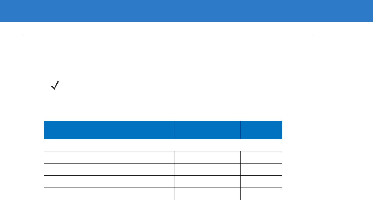
IBM Interface 8 - 3
IBM Parameter Defaults
Table 8-1 lists the defaults for IBM host parameters. To change any option, scan the appropriate bar code(s)
provided in the Parameter Descriptions section beginning on page 8-4.
NOTE See Appendix A, Standard Default Parameters for all user preferences, hosts, symbologies, and
miscellaneous default parameters.
Table 8-1
IBM Host Default Table
Parameter Default Page
Number
IBM 468X/469X Host Parameters
Port Address None Selected 8-4
Convert Unknown to Code 39 Disable 8-5
Ignore Beep Disable 8-6
Ignore Bar Code Configuration Disable 8-6
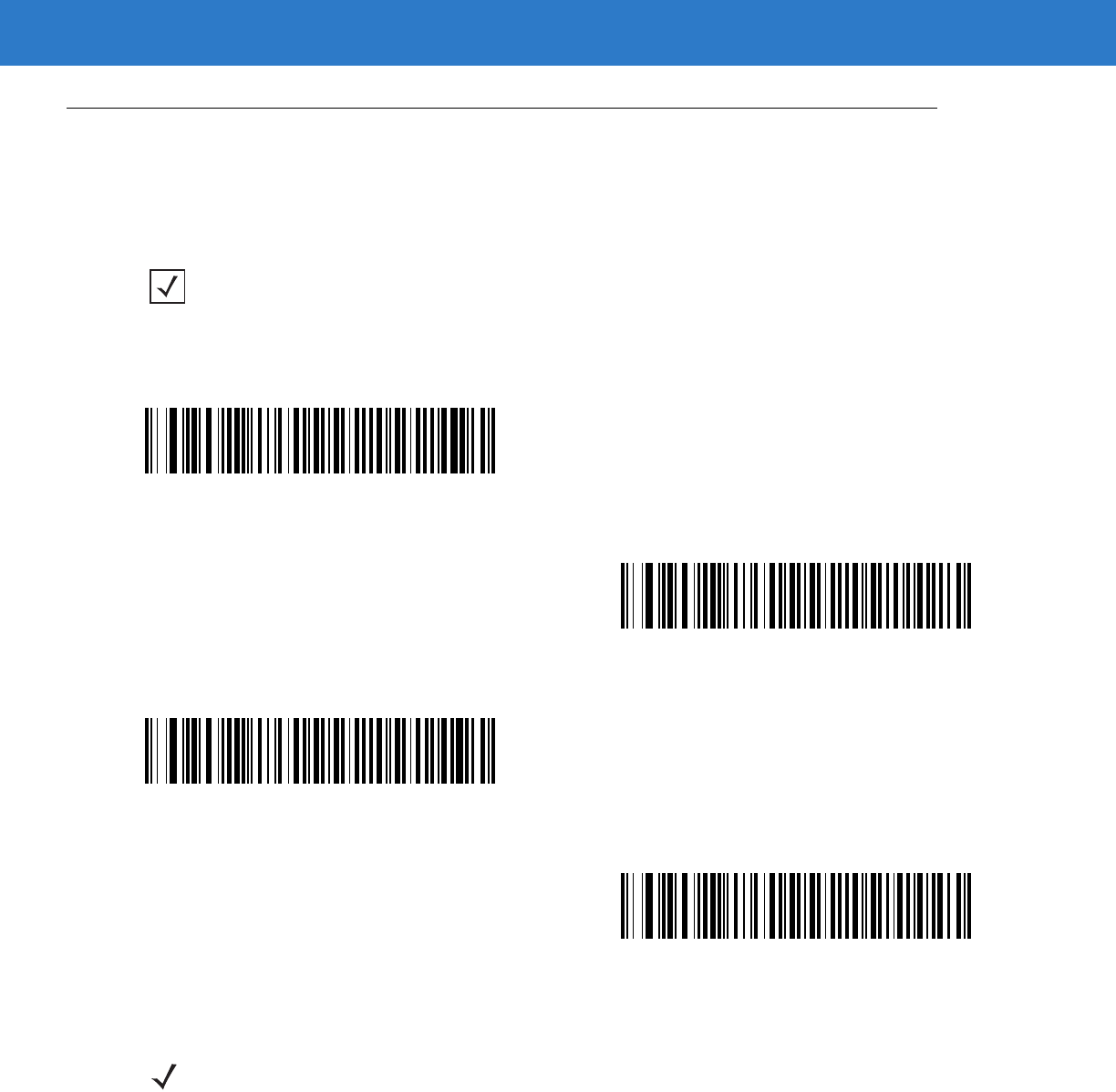
8 - 4 Symbol LS4208 Product Reference Guide
IBM 468X/469X Host Parameters
Port Address
This parameter sets the IBM 468X/469X port used.
NOTE Scanning one of these bar codes enables the RS-485 interface on the scanner.
* None Selected
Hand-held Scanner Emulation (Port 9B)1
Non-IBM Scanner Emulation (Port 5B)
Table-top Scanner Emulation (Port 17)
NOTE 1User selection is required to configure this interface and this is the most common selection.

IBM Interface 8 - 5
Convert Unknown to Code 39
Scan a bar code below to enable or disable the conversion of unknown bar code type data to Code 39.
Enable Convert Unknown to Code 39
*Disable Convert Unknown to Code 39
8 - 6 Symbol LS4208 Product Reference Guide
Optional IBM Parameters
If you configure the scanner and find the settings were not saved, or changed, when the system is restarted scan
the bar codes that follow to override IBM interface defaults.
Scan a bar code below after setting defaults and before configuring the scanner.
Ignore Beep
The host can send a beep request to the scanner. When this parameter is enabled, the request is not sent to the
attached scanner. All directives are still acknowledged to the IBM RS485 host as if it were processed.
Ignore Bar Code Configuration
The host has the ability to enable/disable code types. When this parameter is enabled, the request is not sent to
the attached scanner. All directives are still acknowledged to the IBM RS485 host as if it were processed.
*Disable
Enable
*Disable
Enable

Chapter 9 Wand Emulation Interface
Introduction
This chapter describes how to set up the scanner with a wand emulation host when Wand Emulation
communication is needed. The scanner connects to an external wand decoder or to a decoder integrated in a
mobile computer or Point-of-Sale (POS) terminal.
In this mode the scanner emulates the signal of a wand to make it "readable" by a wand decoder.
Throughout the programming bar code menus, default values are indicated with asterisks (*).
*Transmit Unknown Characters Feature/Option* Indicates Default
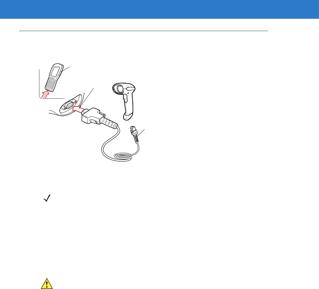
9 - 2 Symbol LS4208 Product Reference Guide
Connecting Using Wand Emulation
To perform Wand Emulation, connect the scanner to a portable data terminal, or a controller which collects the
wand data and interprets it for the host.
Figure 9-1
Wand Emulation Connection
1. Connect the modular connector of the Wand Emulation interface cable to the cable interface port on the
scanner (see Installing the Interface Cable on page 1-3).
2. Connect the other end of the Wand Emulation interface cable to the wand port on the mobile computer or
controller.
3. Select the Wand Emulation host type by scanning the appropriate bar code from Wand Emulation Host Types
on page 9-4.
4. To modify any other parameter options, scan the appropriate bar codes in this chapter.
Wand Port
Mobile Computer
Interface Cable
NOTE Interface cables vary depending on configuration. The connectors illustrated in Figure 9-1 are examples
only. The connectors may be different than those illustrated, but the steps to connect the scanner are the
same.
CAUTION Connect the scanner to 5 volt decoders only. Connecting the scanner to a 12 volt decoder can
damage the scanner and invalidate the warranty.
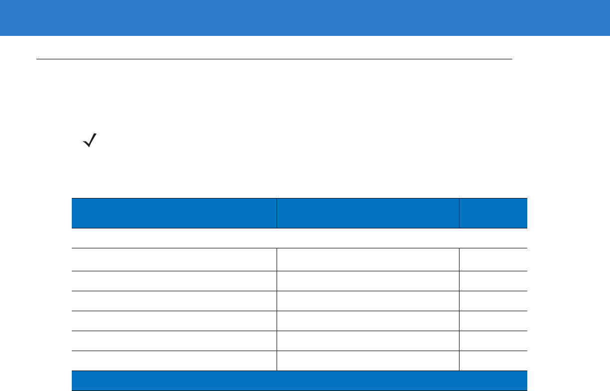
Wand Emulation Interface 9 - 3
Wand Emulation Parameter Defaults
Table 9-1 lists the defaults for Wand Emulation host types. To change any option, scan the appropriate bar code(s)
provided in Wand Emulation Host Parameters beginning on page 9-4.
NOTE See Appendix A, Standard Default Parameters for all user preferences, hosts, symbologies, and
miscellaneous default parameters.
Table 9-1
Wand Emulation Default Table
Parameter Default Page
Number
Wand Emulation Host Parameters
Wand Emulation Host Types Symbol OmniLink Interface Controller
1
9-4
Leading Margin 80 msec 9-5
Polarity Bar High/Margin Low 9-6
Ignore Unknown Characters Send 9-6
Convert All Bar Codes to Code 39 Disable 9-7
Convert Code 39 to Full ASCII Disable 9-8
1
User selection is required to configure this interface and this is the most common selection.
9 - 4 Symbol LS4208 Product Reference Guide
Wand Emulation Host Parameters
Wand Emulation Host Types
Select a Wand Emulation host by scanning one of the bar codes below.
Symbol OmniLink Interface Controller1
Symbol PDT Terminal (MSI)
Symbol PTC Terminal (Telxon)
NOTE 1User selection is required to configure this interface and this is the most common selection.
Wand Emulation Interface 9 - 5
Leading Margin (Quiet Zone)
Scan a bar code below to select a leading margin duration. A leading margin is the time that precedes the first bar
of the scan, (in milliseconds). The minimum allowed value is 80 msec and the maximum is 250 msec. This
parameter accommodates older wand decoders which cannot handle short leading margins.
NOTE 250 msec is the maximum value that this parameter can attain, however, 200 msec is sufficient.
*80 msec
140 msec
200 msec
9 - 6 Symbol LS4208 Product Reference Guide
Polarity
Scan a bar code below to select the polarity required by the decoder. Polarity determines how the scanner's Wand
Emulation interface creates the Digitized Barcode Pattern (DBP). DBP is a digital signal that represents the
scanned bar code. Different decoders expect the DBP to be in a certain format. The DBP either has the "highs"
represent bars and the "lows" represent spaces (margins), or the "highs" represent spaces (margins) and the
"lows" represent bars.
Ignore Unknown Characters
Unknown characters are characters the host does not recognize. When Send Bar Codes With Unknown
Characters is selected, all bar code data is sent except for unknown characters, and no error beeps sound on the
scanner. When Do Not Send Bar Codes With Unknown Characters is selected, bar codes containing at least
one unknown character are not sent to the host, and the scanner emits an error beep.
*Bar High/Margin Low
Bar Low/Margin High
*Send Bar Codes With Unknown Characters
Do Not Send Bar Codes With Unknown Characters

Wand Emulation Interface 9 - 7
Convert All Bar Codes to Code 39
By default, the Wand Emulation interface sends data to the attached host in the same symbology that was
decoded. This can be a problem for customers with older systems that do not recognize newer symbologies (for
example, GS1 DataBar).
Enabling this parameter ignores the original symbology decoded, and outputs the data as if it were a Code 39 bar
code. Any lowercase characters in the original data stream are transmitted as uppercase characters. This also
allows ADF rules.
If Ignore Unknown Characters is enabled, any characters that do not have a corresponding character in the Code
39 symbology set are replaced by a space.
If Ignore Unknown Characters is disabled, if any characters that do not have a corresponding character are
encountered, the scanner emits an error beep and no data is transmitted.
NOTE ADF Note: By default, the Wand Emulation interface does not allow scanned data to be processed by ADF
rules. Enabling this parameter has the side effect of allowing the scanned data to be processed by the
ADF rules (see Chapter 14, Advanced Data Formatting).
Enable Convert to Code 39 for Wand Host
*Disable Convert to Code 39 for Wand Host
9 - 8 Symbol LS4208 Product Reference Guide
Convert Code 39 to Full ASCII
By default, any characters that do not have a corresponding character in the Code 39 symbology set are replaced
by a space. If this parameter is enabled, the data sent to the wand interface is encoded in Code 39 Full ASCII. This
setting requires that the host be able to interpret Code 39 Full ASCII data.
This setting applies only if Convert to Code 39 is also enabled.
*Disable Code 39 Full ASCII Conversion
Enable Code 39 Full ASCII Conversion
NOTE Wand emulation emits an error beep when there is an attempt to send composite data. No data is sent.

Chapter 10 Scanner Emulation Interface
Introduction
This chapter describes how to set up the scanner with a Scanner Emulation host. Use this mode when Scanner
Emulation communication is needed. In this mode, the scanner connects to an external decoder or to a decoder
integrated in a mobile computer or Point-of-Sale (POS) terminal.
Throughout the programming bar code menus, default values are indicated with asterisks (*).
*Parameter Process
and Pass-Through Feature/Option
* Indicates Default
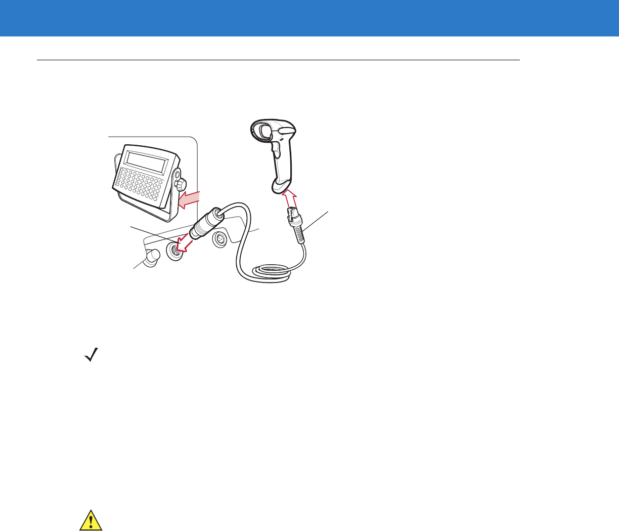
10 - 2 Symbol LS4208 Product Reference Guide
Connecting Using Scanner Emulation
To perform Scanner Emulation, connect the scanner to a mobile computer, or a controller which collects the data
and interprets it for the host.
Figure 10-1
Scanner Emulation Connection
1. Attach the modular connector of the Scanner Emulation interface cable to the cable interface port on the
scanner (see Installing the Interface Cable on page 1-3).
2. Connect the other end of the Scanner Emulation interface cable to the scanner port on the mobile computer or
controller.
3. Scan the Scanner Emulation host bar code from Scanner Emulation Host on page 10-4 to enable the Scanner
Emulation host interface.
4. To modify any other parameter options, scan the appropriate bar codes in this chapter.
Host Port
Connector
Interface Cable
NOTE Interface cables vary depending on configuration. The connectors illustrated in Figure 10-1 are examples
only. The connectors may be different than those illustrated, but the steps to connect the scanner remain
the same.
CAUTION Connect the scanner to 5 volt decoders only. Connecting the scanner to a 12 volt decoder can
damage the scanner and invalidate the warranty.
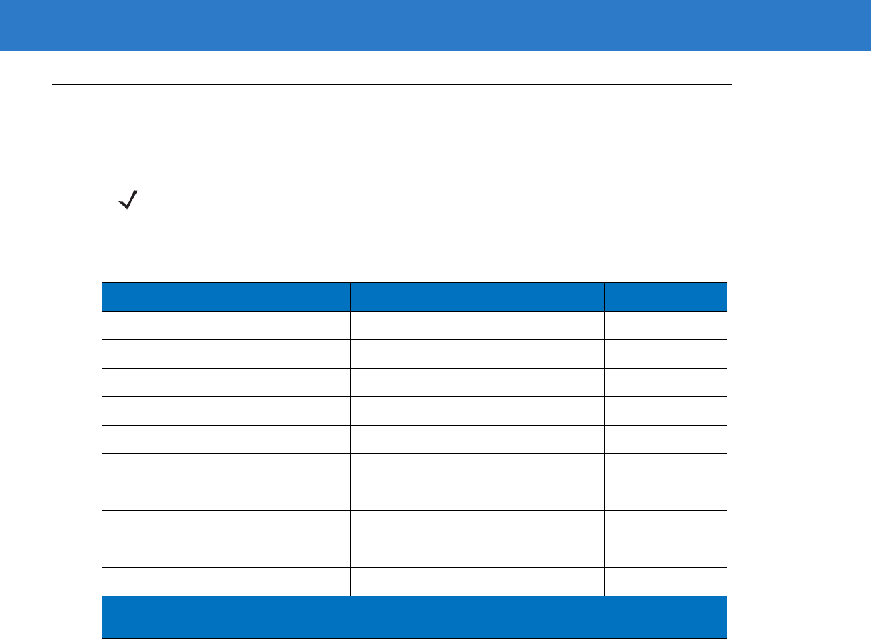
Scanner Emulation Interface 10 - 3
Scanner Emulation Parameter Defaults
Table 10-1 lists the defaults for the Scanner Emulation host. To change any option, scan the appropriate bar
code(s) provided in the Scanner Emulation Host Parameters section beginning on page 10-4.
NOTE See Appendix A, Standard Default Parameters for all user preferences, hosts, symbologies, and
miscellaneous default parameters.
Table 10-1
Scanner Emulation Default Table
Parameter Default Page Number
Beep Style Beep on Successful Transmit 10-4
Parameter Pass-Through Parameter Process and Pass Through 10-5
Convert Newer Code Types Convert Newer Code Types 10-6
Module Width 20 µs 10-7
Convert All Bar Codes to Code 39 Do Not Convert Bar Codes to Code 39 10-7
Code 39 Full ASCII Conversion Disable 10-8
Transmission Timeout 3 Sec 10-9
Ignore Unknown Characters Ignore Unknown Characters 10-10
Leading Margin 2 ms 10-10
Check for Decode LED Check for Decode LED 10-11
1
User selection is required to configure this interface and this is the most common
selection.
10 - 4 Symbol LS4208 Product Reference Guide
Scanner Emulation Host
Scan the bar code below to enable the Scanner Emulation host.
Scanner Emulation Host Parameters
Beep Style
The Scanner Emulation host supports three beep styles.
•
Beep On Successful Transmit: The scanner beeps when the attached decoder issues the decode signal to
the scanner, so the scanner and the attached decoder beep at the same time.
•
Beep At Decode Time: The scanner beeps upon decode. This results in a double beep sequence from most
decoders, since the scanner beeps, and the decoder beeps (at a different frequency) when it successfully
decodes the output.
•
Do Not Beep: Only the attached decoder issues the decode beep.
Undecoded Scanner Emulation Host
*Beep On Successful Transmit
Beep At Decode Time
Do Not Beep

Scanner Emulation Interface 10 - 5
Parameter Pass-Through
The Scanner Emulation host can process parameter bar code messages and send them to the attached decoder.
In this way, customers using Symbol compliant decoders can control the behavior of the entire system by scanning
the necessary parameters only once.
For example, to enable D 2 of 5, scan the D 2 of 5 Enable parameter bar code. The scanner and the attached
decoder both process the parameter.
*Parameter Process and Pass-Through
Parameter Process Only
10 - 6 Symbol LS4208 Product Reference Guide
Convert Newer Code Types
The scanner supports a variety of code types that are not decodable by attached decoder systems. To allow
compatibility in these environments, the scanner converts these code types to more commonly decodable
symbologies, as per the following chart. Symbologies not listed on this chart are transmitted normally.
When decoding these code types with this parameter disabled, the scanner issues Convert Error beeps and
transmits no data.
Scan this code type: Transmitted as:
Code 11 Code 39
Chinese 2 of 5 Code 39
GS1 DataBar (14, Limited, and Expanded) Code 128
Coupon Code Code 128
*Convert Newer Code Types
Reject Newer Code Types
Scanner Emulation Interface 10 - 7
Module Width
The standard module width is 20 µs. For an extremely slow decoder system, select 50 µs Module Width.
Convert All Bar Codes to Code 39
Scan the bar code below to enable or disable the conversion of all bar code data to Code 39.
*20 µs Module Width
50 µs Module Width
*Do Not Convert Bar Codes To Code 39
Convert All To Code 39

10 - 8 Symbol LS4208 Product Reference Guide
Code 39 Full ASCII Conversion
By default, any characters that do not have a corresponding character in the Code 39 symbology set are replaced
by a space. If this parameter is enabled, the data sent to the Scanner Emulation host is encoded in Code 39 Full
ASCII. The host must be able to interpret Code 39 Full ASCII data. This setting applies only if Convert to Code 39
is also enabled.
*Disable Convert Code 39 To Full ASCII
Enable Convert Code 39 To Full ASCII
Scanner Emulation Interface 10 - 9
Transmission Timeout
The Scanner Emulation host transmits bar code data to the attached decoder and waits for the decoder to assert
the Decode signal, indicating successful transmission. If, after a specified amount of time, the Decode signal is not
asserted (indicating that the attached decoder has not successfully received the bar code data), the scanner issues
transmit error beeps.
Scan a bar code below to select the desired transmission timeout.
*3 Second Transmission Timeout
4 Second Transmission Timeout
5 Second Transmission Timeout
10 Second Transmission Timeout
30 Second Transmission Timeout
10 - 10 Symbol LS4208 Product Reference Guide
Ignore Unknown Characters
Unknown characters are characters the decoder does not recognize. When Ignore Unknown Characters is
selected, all bar code data is sent except for unknown characters, and no error beeps sound. When Convert Error
on Unknown Characters is selected, bar codes containing at least one unknown character are not sent to the
decoder, and a convert error beep sounds.
Leading Margin
Scan a bar code below to select a leading margin duration.
*Ignore Unknown Characters
Convert Error On Unknown Characters
1 ms Leading Margin
*2 ms Leading Margin
3 ms Leading Margin
Scanner Emulation Interface 10 - 11
Leading Margin (continued)
Check For Decode LED
The attached decoder normally asserts the Decode line to signal to the Scanner Emulation host that it successfully
decoded the transmitted bar code. Some decoders, however, do not assert the Decode signal. In this case, the
scanner emits transmit error beeps to indicate that the bar code was not successfully transmitted. Scan the Ignore
Decode LED bar code to disable the Transmit Error beeps.
5 ms Leading Margin
10 ms Leading Margin
*Check For Decode LED
Ignore Decode LED

10 - 12 Symbol LS4208 Product Reference Guide

Chapter 11 123Scan
Introduction
123Scan is a Windows®-based utility that programs the scanner with all parameters including ADF rules. An ADF
rule modifies bar code data before it is sent to the host to ensure compatibility between bar coded data and the
host application. Scanners can be programmed via PC download or by scanning a sheet of bar codes generated
by the utility. Scanner programming is saved in a file for electronic distribution. The 123Scan program includes a
help file.
Communication with 123Scan
To communicate with the 123Scan program which runs on a host computer running a Windows operating system,
use an RS-232 cable to connect the scanner to the host computer (see Connecting an RS-232 Interface on page
6-2).
123Scan requirements:
•
Host computer with Windows 98, Windows NT, Windows 2000, or Windows XP
•
Scanner
•
RS-232 cable.
123Scan Parameter
To communicate with the 123Scan program, load 123Scan, included in the documentation CD-ROM, onto the host
computer, and scan the bar code below. Refer to 123Scan instructions for programming the scanner.
Scan the bar code below to enable the 123Scan interface on the scanner.
123Scan Configuration

11 - 2 Symbol LS4208 Product Reference Guide

Chapter 12 Symbologies
Introduction
This chapter describes symbology features and provides the programming bar codes for selecting these features.
Before programming, follow the instructions in Chapter 1, Getting Started.
The scanner is shipped with the settings shown in Table 12-1 on page 12-2 (also see Appendix A, Standard Default
Parameters for all host device and miscellaneous defaults). If the default values suit requirements, programming is
not necessary.
To set feature values, scan a single bar code or a short bar code sequence. The settings are stored in non-volatile
memory and are preserved even when the scanner is powered down.
If not using a Synapse or USB cable, select a host type (see each host chapter for specific host information) after
the power-up beeps sound. This is only necessary upon the first power-up when connected to a new host.
To return all features to default values, scan the appropriate default bar code on page 4-3. Throughout the
programming bar code menus, default values are indicated with asterisks (*).
Scanning Sequence Examples
In most cases, scanning one bar code sets the parameter value. For example, to transmit bar code data without the
UPC-A check digit, simply scan the Do Not Transmit UPC-A Check Digit bar code under Transmit UPC-A Check
Digit on page 12-14. The scanner issues a fast warble beep and the LED turns green, signifying a successful
parameter entry.
Other parameters, such as Set Length(s) for D 2 of 5, require scanning several bar codes. See the individual
parameter, such as Set Length(s) for D 2 of 5, for this procedure.
*Enable UPC-A Feature/Option
* Indicates Default
12 - 2 Symbol LS4208 Product Reference Guide
Errors While Scanning
Unless otherwise specified, to correct an error during a scanning sequence, just re-scan the correct parameter.
Symbology Parameter Defaults
Table 12-1 lists the defaults for all symbologies parameters. To change any option, scan the appropriate bar
code(s) provided in the Symbologies Parameters section beginning on page 12-6.
NOTE See Appendix A, Standard Default Parameters for all user preferences, hosts, symbologies and
miscellaneous default parameters.
Table 12-1
Symbology Parameter Defaults
Parameter Default Page
Number
UPC/EAN
UPC-A Enable 12-6
UPC-E Enable 12-6
UPC-E1 Disable 12-7
EAN-8/JAN 8 Enable 12-8
EAN-13/JAN 13 Enable 12-8
Bookland EAN Disable 12-9
Decode UPC/EAN/JAN Supplementals
(2 and 5 digits) Ignore 12-9
Decode UPC/EAN/JAN Supplemental
Redundancy 712-14
Transmit UPC-A Check Digit Enable 12-14
Transmit UPC-E Check Digit Enable 12-15
Transmit UPC-E1 Check Digit Enable 12-15
UPC-A Preamble System Character 12-16
UPC-E Preamble System Character 12-17
UPC-E1 Preamble System Character 12-18
Convert UPC-E to A Disable 12-19
Convert UPC-E1 to A Disable 12-19
EAN-8/JAN-8 Extend Disable 12-20
Bookland ISBN Format ISBN-10 12-21
Symbologies 12 - 3
UCC Coupon Extended Code Disable 12-22
Code 128
Code 128 Enable 12-23
GS1-128 (formerly UCC/EAN-128) Enable 12-23
ISBT 128 (non-concatenated) Enable 12-24
Code 39
Code 39 Enable 12-25
Trioptic Code 39 Disable 12-25
Convert Code 39 to Code 32
(Italian Pharmacy Code) Disable 12-26
Code 32 Prefix Disable 12-26
Set Length(s) for Code 39 2 to 55 12-27
Code 39 Check Digit Verification Disable 12-28
Transmit Code 39 Check Digit Disable 12-29
Code 39 Full ASCII Conversion Disable 12-30
Buffer Code 39 Disable 12-31
Code 93
Code 93 Disable 12-34
Set Length(s) for Code 93 4 to 55 12-34
Code 11
Code 11 Disable 12-36
Set Lengths for Code 11 4 to 55 12-36
Code 11 Check Digit Verification Disable 12-38
Transmit Code 11 Check Digit(s) Disable 12-39
Interleaved 2 of 5 (ITF)
Interleaved 2 of 5 (ITF) Enable 12-40
Set Lengths for I 2 of 5 14 12-40
I 2 of 5 Check Digit Verification Disable 12-42
Transmit I 2 of 5 Check Digit Disable 12-43
Convert I 2 of 5 to EAN-13 Disable 12-43
Table 12-1
Symbology Parameter Defaults (Continued)
Parameter Default Page
Number
12 - 4 Symbol LS4208 Product Reference Guide
Discrete 2 of 5 (DTF)
Discrete 2 of 5 Disable 12-44
Set Length(s) for D 2 of 5 12 12-44
Chinese 2 of 5
Enable/Disable Chinese 2 of 5 Disable 12-46
Codabar (NW - 7)
Codabar Disable 12-47
Set Lengths for Codabar 5 to 55 12-47
CLSI Editing Disable 12-49
NOTIS Editing Disable 12-49
MSI
MSI Disable 12-50
Set Length(s) for MSI 2 to 55 12-50
MSI Check Digits One 12-51
Transmit MSI Check Digit Disable 12-52
MSI Check Digit Algorithm Mod 10/Mod 10 12-52
GS1 DataBar (formerly RSS - Reduced Space Symbology)
GS1 DataBar-14 Disable 12-53
GS1 DataBar Limited Disable 12-53
GS1 DataBar Expanded Disable 12-53
Convert GS1 DataBar to UPC/EAN Disable 12-54
PDF
PDF417 Enable (LS4208-PR
PDF417 version only) 12-55
MicroPDF
MicroPDF417 Disable 12-55
MicroPDF Performance Standard Performance
for MicroPDF 12-56
Transmit
Transmit Symbol in Codeword Format Disable 12-57
Transmit Unknown Codewords Disable 12-58
Table 12-1
Symbology Parameter Defaults (Continued)
Parameter Default Page
Number
Symbologies 12 - 5
Character
Escape Character None 12-58
Delete Character Set ECI’s Transmit 12-59
Composite
Composite CC-C Disable 12-60
Composite CC-A/B Disable 12-60
UPC Composite Mode UPC Always Linked 12-61
Composite Beep Mode Beep as Each Code
Type is Decoded 12-62
Symbology - Specific Security Levels
Redundancy Level 1 12-63
Security Levels 0 12-65
Bi-directional Redundancy Disable 12-66
Intercharacter Gap Normal Intercharacter
Gap 12-66
Table 12-1
Symbology Parameter Defaults (Continued)
Parameter Default Page
Number
12 - 6 Symbol LS4208 Product Reference Guide
UPC/EAN
Enable/Disable UPC-A/UPC-E
To enable or disable UPC-A or UPC-E, scan the appropriate bar code below.
*Enable UPC-A
Disable UPC-A
*Enable UPC-E
Disable UPC-E

Symbologies 12 - 7
Enable/Disable UPC-E1
UPC-E1 is disabled by default.
To enable or disable UPC-E1, scan the appropriate bar code below.
NOTE UPC-E1 is not a UCC (Uniform Code Council) approved symbology.
Enable UPC-E1
*Disable UPC-E1

12 - 8 Symbol LS4208 Product Reference Guide
Enable/Disable EAN-13/EAN-8
To enable or disable EAN-13 or EAN-8, scan the appropriate bar code below.
*Enable EAN-13
Disable EAN-13
*Enable EAN-8
Disable EAN-8
Symbologies 12 - 9
Enable/Disable Bookland EAN
To enable or disable Bookland EAN, scan the appropriate bar code below.
Decode UPC/EAN/JAN Supplementals
Supplementals are additionally appended characters (2 or 5) according to specific code format conventions (e.g.,
UPC A+2, UPC E+2, EAN 8+2). The following options are available:
•
If you select Ignore UPC/EAN with Supplementals, and the scanner is presented with a UPC/EAN plus
supplemental symbol, the scanner decodes UPC/EAN and ignores the supplemental characters.
•
If you select Decode UPC/EAN with Supplementals, the scanner only decodes UPC/EAN symbols with
supplemental characters, and ignores symbols without supplementals.
•
If you select Autodiscriminate UPC/EAN Supplementals, the scanner decodes UPC/EAN symbols with
supplemental characters immediately. If the symbol does not have a supplemental, the scanner must decode
the bar code the number of times set via UPC/EAN/JAN Supplemental Redundancy on page 12-14 before
transmitting its data to confirm that there is no supplemental.
•
If you select one of the following Supplemental Mode options, the scanner immediately transmits EAN-13
bar codes starting with that prefix that have supplemental characters. If the symbol does not have a
supplemental, the scanner must decode the bar code the number of times set via UPC/EAN/JAN
Supplemental Redundancy on page 12-14 before transmitting its data to confirm that there is no
supplemental. The scanner transmits UPC/EAN bar codes that do not have that prefix immediately.
• Enable 378/379 Supplemental Mode
• Enable 978/979 Supplemental Mode
Enable Bookland EAN
*Disable Bookland EAN
NOTE If you enable Bookland EAN, select a Bookland ISBN Format on page 12-21. Also select either Decode
UPC/EAN Supplementals, Autodiscriminate UPC/EAN Supplementals, or Enable 978/979 Supplemental
Mode in Decode UPC/EAN/JAN Supplementals.
NOTE If you select 978/979 Supplemental Mode and are scanning Bookland EAN bar codes, see Enable/Disable
Bookland EAN to enable Bookland EAN, and select a format using Bookland ISBN Format on page 12-21.

12 - 10 Symbol LS4208 Product Reference Guide
• Enable 977 Supplemental Mode
• Enable 414/419/434/439 Supplemental Mode
• Enable 491 Supplemental Mode
• Enable Smart Supplemental Mode - applies to EAN-13 bar codes starting with any prefix listed
previously.
• Supplemental User-Programmable Type 1 - applies to EAN-13 bar codes starting with a 3-digit
user-defined prefix. Set this 3-digit prefix using Supplemental User-Programmable 1.
• Supplemental User-Programmable Type 1 and 2 - applies to EAN-13 bar codes starting with either of
two 3-digit user-defined prefixes. Set the 3-digit prefixes using Supplemental User-Programmable 1 and
Supplemental User-Programmable 2.
• Smart Supplemental Plus User-Programmable 1 - applies to EAN-13 bar codes starting with any prefix
listed previously or the user-defined prefix set using Supplemental User-Programmable 1.
• Smart Supplemental Plus User-Programmable 1 and 2 - applies to EAN-13 bar codes starting with any
prefix listed previously or one of the two user-defined prefixes set using Supplemental
User-Programmable 1 and Supplemental User-Programmable 2.
•
Select Supplemental User-Programmable 1 to set a 3-digit prefix. Then select the 3 digits using the
numeric bar codes beginning on page D-1.
•
Select Supplemental User-Programmable 2 to set a second 3-digit prefix. Then select the 3 digits using the
numeric bar codes beginning on page D-1.
NOTE To minimize the risk of invalid data transmission, select either to decode or ignore supplemental
characters.

Symbologies 12 - 11
Decode UPC/EAN/JAN Supplementals (continued)
*Ignore UPC/EAN/JAN With Supplementals
Decode UPC/EAN/JAN Only With Supplementals
Autodiscriminate UPC/EAN/JAN Supplementals
Enable 378/379 Supplemental Mode
Enable 978/979 Supplemental Mode
Enable 977 Supplemental Mode
12 - 12 Symbol LS4208 Product Reference Guide
Decode UPC/EAN/JAN Supplementals (continued)
Enable 414/419/434/439 Supplemental Mode
Enable 491 Supplemental Mode
Enable Smart Supplemental Mode
Supplemental User-Programmable Type 1
Supplemental User-Programmable Type 1 and 2

Symbologies 12 - 13
Decode UPC/EAN/JAN Supplementals (continued)
Smart Supplemental Plus User-Programmable 1
Smart Supplemental Plus User-Programmable 1 and 2
Supplemental User-Programmable 1
Supplemental User-Programmable 2

12 - 14 Symbol LS4208 Product Reference Guide
UPC/EAN/JAN Supplemental Redundancy
With Autodiscriminate UPC/EAN/JAN Supplementals or one of the supplemental modes selected, this option
adjusts the number of times a symbol without supplementals is decoded before transmission. The range is from 2
to 22 times. Five or above is recommended when decoding a mix of UPC/EAN symbols with and without
supplementals, and the autodiscriminate option is selected. The default is set at 7.
Scan the bar code below to set a decode redundancy value. Next, scan two numeric bar codes in Appendix D,
Numeric Bar Codes. Single digit numbers must have a leading zero. To correct an error or change a selection,
scan Cancel on page D-3.
Transmit UPC-A Check Digit
The check digit is the last character of the symbol used to verify the integrity of the data. Scan the appropriate bar
code below to transmit the bar code data with or without the UPC-A check digit. It is always verified to guarantee
the integrity of the data.
UPC/EAN/JAN Supplemental Redundancy
*Transmit UPC-A Check Digit
Do Not Transmit UPC-A Check Digit
Symbologies 12 - 15
Transmit UPC-E Check Digit
The check digit is the last character of the symbol used to verify the integrity of the data. Scan the appropriate bar
code below to transmit the bar code data with or without the UPC-E check digit. It is always verified to guarantee
the integrity of the data.
Transmit UPC-E1 Check Digit
The check digit is the last character of the symbol used to verify the integrity of the data. Scan the appropriate bar
code below to transmit the bar code data with or without the UPC-E1 check digit. It is always verified to guarantee
the integrity of the data.
*Transmit UPC-E Check Digit
Do Not Transmit UPC-E Check Digit
*Transmit UPC-E1 Check Digit
Do Not Transmit UPC-E1 Check Digit

12 - 16 Symbol LS4208 Product Reference Guide
UPC-A Preamble
Preamble characters are part of the UPC symbol consisting of Country Code and System Character. Three options
are given for transmitting UPC-A preamble to the host device: transmit System Character only, transmit System
Character and Country Code (“0” for USA), and no preamble transmitted. Scan a bar code below to match the host
system.
No Preamble
(<DATA>)
*System Character
(<SYSTEM CHARACTER> <DATA>)
System Character & Country Code
(< COUNTRY CODE>
<SYSTEM CHARACTER> <DATA>)

Symbologies 12 - 17
UPC-E Preamble
Preamble characters are part of the UPC symbol consisting of Country Code and System Character. Three options
are given for transmitting UPC-E preamble to the host device: transmit System Character only, transmit System
Character and Country Code (“0” for USA), and no preamble transmitted. Scan a bar code below to match the host
system.
No Preamble
(<DATA>)
*System Character
(<SYSTEM CHARACTER> <DATA>)
System Character & Country Code
(< COUNTRY CODE>
<SYSTEM CHARACTER> <DATA>)

12 - 18 Symbol LS4208 Product Reference Guide
UPC-E1 Preamble
Preamble characters are part of the UPC symbol consisting of Country Code and System Character. Three options
are given for transmitting UPC-E1 preamble to the host device: transmit System Character only, transmit System
Character and Country Code (“0” for USA), and no preamble transmitted. Scan a bar code below to match the host
system.
No Preamble
(<DATA>)
*System Character
(<SYSTEM CHARACTER> <DATA>)
System Character & Country Code
(< COUNTRY CODE>
<SYSTEM CHARACTER> <DATA>)
Symbologies 12 - 19
Convert UPC-E to UPC-A
Enable this to convert UPC-E (zero suppressed) decoded data to UPC-A format before transmission. After
conversion, the data follows UPC-A format and is affected by UPC-A programming selections (e.g., Preamble,
Check Digit).
When disabled, UPC-E decoded data is transmitted as UPC-E data, without conversion.
Convert UPC-E1 to UPC-A
Enable this to convert UPC-E1 decoded data to UPC-A format before transmission. After conversion, the data
follows UPC-A format and is affected by UPC-A programming selections (e.g., Preamble, Check Digit).
When disabled, UPC-E1 decoded data is transmitted as UPC-E1 data, without conversion.
Convert UPC-E to UPC-A
(Enable)
*Do Not Convert UPC-E to UPC-A
(Disable)
Convert UPC-E1 to UPC-A
(Enable)
*Do Not Convert UPC-E1 to UPC-A
(Disable)

12 - 20 Symbol LS4208 Product Reference Guide
EAN-8/JAN-8 Extend
When enabled, this parameter adds five leading zeros to decoded EAN-8 symbols to make them compatible in
format to EAN-13 symbols.
When disabled, EAN-8 symbols are transmitted as is.
Enable EAN/JAN Zero Extend
*Disable EAN/JAN Zero Extend
Symbologies 12 - 21
Bookland ISBN Format
If you enabled Bookland EAN using Enable/Disable Bookland EAN on page 12-9, select one of the following
formats for Bookland data:
•
Bookland ISBN-10 - The scanner reports Bookland data starting with 978 in traditional 10-digit format with
the special Bookland check digit for backward-compatibility. Data starting with 979 is not considered
Bookland in this mode.
•
Bookland ISBN-13 - The scanner reports Bookland data (starting with either 978 or 979) as EAN-13 in
13-digit format to meet the 2007 ISBN-13 protocol.
*Bookland ISBN-10
Bookland ISBN-13
NOTE For Bookland EAN to function properly, first enable Bookland EAN using Enable/Disable Bookland EAN on
page 12-9, then select either Decode UPC/EAN Supplementals, Autodiscriminate UPC/EAN
Supplementals, or Enable 978/979 Supplemental Mode in Decode UPC/EAN/JAN Supplementals on page
12-9.

12 - 22 Symbol LS4208 Product Reference Guide
UCC Coupon Extended Code
When enabled, this parameter decodes UPCA bar codes starting with digit ‘5’, EAN-13 bar codes starting with digit
‘99’, and UPCA/GS1-128 Coupon Codes. UPCA, EAN-13 and GS1-128 must be enabled to scan all types of
Coupon Codes.
Enable UCC Coupon Extended Code
*Disable UCC Coupon Extended Code
NOTE Use the UPC/EAN/JAN Supplemental Redundancy parameter to control autodiscrimination of the
GS1-128 (right half) of a coupon code.
Symbologies 12 - 23
Code 128
Enable/Disable Code 128
To enable or disable Code 128, scan the appropriate bar code below.
Enable/Disable GS1-128 (formerly UCC/EAN-128)
To enable or disable GS1-128, scan the appropriate bar code below.
*Enable Code 128
Disable Code 128
*Enable GS1-128
Disable GS1-128

12 - 24 Symbol LS4208 Product Reference Guide
Enable/Disable ISBT 128
ISBT 128 is a variant of Code 128 used in the blood bank industry. Scan the appropriate bar code below to enable
or disable ISBT 128. If necessary, the host must perform concatenation of the ISBT data.
*Enable ISBT 128
Disable ISBT 128
Symbologies 12 - 25
Code 39
Enable/Disable Code 39
To enable or disable Code 39, scan the appropriate bar code below.
Enable/Disable Trioptic Code 39
Trioptic Code 39 is a variant of Code 39 used in the marking of computer tape cartridges. Trioptic Code 39 symbols
always contain six characters. To enable or disable Trioptic Code 39, scan the appropriate bar code below.
*Enable Code 39
Disable Code 39
Enable Trioptic Code 39
*Disable Trioptic Code 39
NOTE Trioptic Code 39 and Code 39 Full ASCII cannot be enabled simultaneously.
12 - 26 Symbol LS4208 Product Reference Guide
Convert Code 39 to Code 32
Code 32 is a variant of Code 39 used by the Italian pharmaceutical industry. Scan the appropriate bar code below
to enable or disable converting Code 39 to Code 32.
Code 32 Prefix
Scan the appropriate bar code below to enable or disable adding the prefix character “A” to all Code 32 bar codes.
NOTE Code 39 must be enabled for this parameter to function.
Enable Convert Code 39 to Code 32
*Disable Convert Code 39 to Code 32
NOTE Convert Code 39 to Code 32 must be enabled for this parameter to function.
Enable Code 32 Prefix
*Disable Code 32 Prefix

Symbologies 12 - 27
Set Lengths for Code 39
he length of a code refers to the number of characters (i.e., human readable characters), including check digit(s)
the code contains. Set lengths for Code 39 to any length, one or two discrete lengths, or lengths within a specific
range. If Code 39 Full ASCII is enabled, Length Within a Range or Any Length are the preferred options.
•
One Discrete Length - Select this option to decode only Code 39 symbols containing a selected length.
Select the length using the numeric bar codes in Appendix D, Numeric Bar Codes. For example, to decode
only Code 39 symbols with 14 characters, scan Code 39 - One Discrete Length, then scan 1 followed by 4.
To correct an error or change the selection, scan Cancel on page D-3.
•
Two Discrete Lengths - Select this option to decode only Code 39 symbols containing either of two
selected lengths. Select lengths using the numeric bar codes in Appendix D, Numeric Bar Codes. For
example, to decode only those Code 39 symbols containing either 2 or 14 characters, select Code 39 - Two
Discrete Lengths, then scan 0, 2, 1, and then 4. To correct an error or change the selection, scan
Cancel on page D-3.
•
Length Within Range - Select this option to decode a Code 39 symbol with a specific length range.
Select lengths using numeric bar codes in Appendix D, Numeric Bar Codes. For example, to decode
Code 39 symbols containing between 4 and 12 characters, first scan Code 39 - Length Within Range.
Then scan 0, 4, 1, and 2 (single digit numbers must always be preceded by a leading zero). To correct an
error or change the selection, scan Cancel on page D-3.
•
Any Length - Select this option to decode Code 39 symbols containing any number of characters within the
scanner capability.
NOTE When setting lengths for different bar code types by scanning single digit numbers, single digit numbers
must always be preceded by a leading zero.
12 - 28 Symbol LS4208 Product Reference Guide
Set Lengths for Code 39
Code 39 Check Digit Verification
When this feature is enabled, the scanner checks the integrity of all Code 39 symbols to verify that the data
complies with specified check digit algorithm. Only Code 39 symbols which include a modulo 43 check digit are
decoded. Enable this feature if the Code 39 symbols contain a Modulo 43 check digit.
Code 39 - One Discrete Length
Code 39 - Two Discrete Lengths
Code 39 - Length Within Range
Code 39 - Any Length
Enable Code 39 Check Digit
*Disable Code 39 Check Digit

Symbologies 12 - 29
Transmit Code 39 Check Digit
Scan the appropriate bar code below to transmit Code 39 data with or without the check digit.
Transmit Code 39 Check Digit
(Enable)
*Do Not Transmit Code 39 Check Digit
(Disable)
NOTE Code 39 Check Digit Verification must be enabled for this parameter to function.

12 - 30 Symbol LS4208 Product Reference Guide
Code 39 Full ASCII Conversion
Code 39 Full ASCII is a variant of Code 39 which pairs characters to encode the full ASCII character set. To enable
or disable Code 39 Full ASCII, scan the appropriate bar code below.
Enable Code 39 Full ASCII
*Disable Code 39 Full ASCII
NOTE Trioptic Code 39 and Code 39 Full ASCII cannot be enabled simultaneously.
Code 39 Full ASCII to Full ASCII Correlation is host-dependent and is described in the ASCII Character
Set table for the appropriate interface. See ASCII Character Set for Keyboard Wedge on page 5-13, ASCII
Character Set for RS-232 on page 6-18, and ASCII Character Set for USB on page 7-12 for the
appropriate interface.

Symbologies 12 - 31
Code 39 Buffering (Scan & Store)
This feature allows the scanner to accumulate data from multiple Code 39 symbols.
Selecting the Scan and Store option (Buffer Code 39) temporarily buffers all Code 39 symbols having a leading
space as a first character for later transmission. The leading space is not buffered.
Decode of a valid Code 39 symbol with no leading space causes transmission in sequence of all buffered data in a
first-in first-out format, plus transmission of the “triggering” symbol. See the following pages for further details.
When the Do Not Buffer Code 39 option is selected, all decoded Code 39 symbols are transmitted immediately
without being stored in the buffer.
This feature affects Code 39 only. If selecting Buffer Code 39, we recommend configuring the scanner to decode
Code 39 symbology only.
While there is data in the transmission buffer, selecting Do Not Buffer Code 39 is not allowed. The buffer holds
200 bytes of information.
To disable Code 39 buffering when there is data in the transmission buffer, first force the buffer transmission
(see Transmit Buffer on page 12-32) or clear the buffer.
Buffer Data
To buffer data, Code 39 buffering must be enabled and a Code 39 symbol must be read with a space immediately
following the start pattern.
•
Unless the data overflows the transmission buffer, the scanner issues a low/high beep to indicate successful
decode and buffering. (For overflow conditions, see Overfilling Transmission Buffer.)
•
The scanner adds the decoded data excluding the leading space to the transmission buffer.
•
No transmission occurs.
Buffer Code 39
(Enable)
*Do Not Buffer Code 39
(Disable)
12 - 32 Symbol LS4208 Product Reference Guide
Clear Transmission Buffer
To clear the transmission buffer, scan the Clear Buffer bar code below, which contains only a start character, a
dash (minus), and a stop character.
•
The scanner issues a short high/low/high beep.
•
The scanner erases the transmission buffer.
•
No transmission occurs.
Transmit Buffer
There are two methods to transmit the Code 39 buffer.
1. Scan the Transmit Buffer bar code below which contains only a start character, a plus (+), and a stop
character.
•The scanner transmits and clears the buffer.
•The scanner issues a low/high beep.
2. Scan a Code 39 bar code with a leading character other than a space.
•The scanner appends new decode data to buffered data.
•The scanner transmits and clears the buffer.
•The scanner signals that the buffer was transmitted with a low/high beep.
•Scanner transmits and clears the buffer.
Clear Buffer
NOTE Because the Clear Buffer contains only the dash (minus) character, set the Code 39 length to include
length 1 before scanning this bar code.
Transmit Buffer
NOTE Because the Transmit Buffer contains only a plus (+) character, set the Code 39 length to include length 1
before scanning this bar code.

Symbologies 12 - 33
Overfilling Transmission Buffer
The Code 39 buffer holds 200 characters. If the symbol just read results in an overflow of the transmission buffer:
•
The scanner indicates that the symbol was rejected by issuing three long, high beeps.
•
No transmission occurs. The data in the buffer is not affected.
Attempt to Transmit an Empty Buffer
If the symbol just read was the Transmit Buffer symbol and the Code 39 buffer is empty:
•
A short low/high/low beep signals that the buffer is empty.
•
No transmission occurs.
•
The buffer remains empty.

12 - 34 Symbol LS4208 Product Reference Guide
Code 93
Enable/Disable Code 93
To enable or disable Code 93, scan the appropriate bar code below.
Set Lengths for Code 93
The length of a code refers to the number of characters (i.e., human readable characters), including check digit(s)
the code contains. Set lengths for Code 93 to any length, one or two discrete lengths, or lengths within a specific
range.
•
One Discrete Length - Select this option to decode only Code 93 symbols containing a selected length.
Select the length using the numeric bar codes in Appendix D, Numeric Bar Codes. For example, to decode
only Code 93 symbols with 14 characters, scan Code 93 - One Discrete Length, then scan 1 followed by 4.
To correct an error or to change the selection, scan Cancel on page D-3.
•
Two Discrete Lengths - Select this option to decode only Code 93 symbols containing either of two
selected lengths. Select lengths using the numeric bar codes in Appendix D, Numeric Bar Codes. For
example, to decode only those Code 93 symbols containing either 2 or 14 characters, select Code 93 - Two
Discrete Lengths, then scan 0, 2, 1, and then 4. To correct an error or to change the selection, scan
Cancel on page D-3.
•
Length Within Range - Select this option to decode a Code 93 symbol with a specific length range.
Select lengths using the numeric bar codes in Appendix D, Numeric Bar Codes. For example, to decode
Code 93 symbols containing between 4 and 12 characters, first scan Code 93 - Length Within Range.
Then scan 0, 4, 1, and 2 (single digit numbers must always be preceded by a leading zero). To correct an
error or change the selection, scan Cancel on page D-3.
•
Any Length - Scan this option to decode Code 93 symbols containing any number of characters within the
scanner’s capability.
Enable Code 93
*Disable Code 93
Symbologies 12 - 35
Set Lengths for Code 93 (continued)
Code 93 - One Discrete Length
Code 93 - Two Discrete Lengths
Code 93 - Length Within Range
Code 93 - Any Length

12 - 36 Symbol LS4208 Product Reference Guide
Code 11
Code 11
To enable or disable Code 11, scan the appropriate bar code below.
Set Lengths for Code 11
The length of a code refers to the number of characters (i.e., human readable characters), including check digit(s)
the code contains. Set lengths for Code 11 to any length, one or two discrete lengths, or lengths within a specific
range.
•
One Discrete Length - Select this option to decode only Code 11 symbols containing a selected length.
Select the length using the numeric bar codes in Appendix D, Numeric Bar Codes. For example, to decode
only Code 11 symbols with 14 characters, scan Code 11 - One Discrete Length, then scan 1 followed by 4.
To correct an error or to change the selection, scan Cancel on page D-3.
•
Two Discrete Lengths - Select this option to decode only Code 11 symbols containing either of two
selected lengths. Select lengths using the numeric bar codes in Appendix D, Numeric Bar Codes. For
example, to decode only those Code 11 symbols containing either 2 or 14 characters, select Code 11 - Two
Discrete Lengths, then scan 0, 2, 1, and then 4. To correct an error or to change the selection, scan
Cancel on page D-3.
•
Length Within Range - Select this option to decode a Code 11 symbol with a specific length range.
Select lengths using numeric bar codes in Appendix D, Numeric Bar Codes. For example, to decode
Code 11 symbols containing between 4 and 12 characters, first scan Code 11 - Length Within Range.
Then scan 0, 4, 1, and 2 (single digit numbers must always be preceded by a leading zero). To correct an
error or change the selection, scan Cancel on page D-3.
•
Any Length - Scan this option to decode Code 11 symbols containing any number of characters within the
scanner capability.
Enable Code 11
*Disable Code 11

Symbologies 12 - 37
Set Lengths for Code 11 (continued)
Code 11 - One Discrete Length
Code 11 - Two Discrete Lengths
Code 11 - Length Within Range
Code 11 - Any Length

12 - 38 Symbol LS4208 Product Reference Guide
Code 11 Check Digit Verification
This feature allows the scanner to check the integrity of all Code 11 symbols to verify that the data complies with
the specified check digit algorithm. This selects the check digit mechanism for the decoded Code 11 bar code. The
options are to check for one check digit, check for two check digits, or disable the feature.
To enable this feature, scan the bar code below corresponding to the number of check digits encoded in your Code
11 symbols.
*Disable
One Check Digit
Two Check Digits

Symbologies 12 - 39
Transmit Code 11 Check Digits
This feature selects whether or not to transmit the Code 11 check digit(s).
Transmit Code 11 Check Digit(s)
(Enable)
*Do Not Transmit Code 11 Check Digit(s)
(Disable)
NOTE Code 11 Check Digit Verification must be enabled for this parameter to function.
12 - 40 Symbol LS4208 Product Reference Guide
Interleaved 2 of 5 (ITF)
Enable/Disable Interleaved 2 of 5
To enable or disable Interleaved 2 of 5, scan the appropriate bar code below, and select an Interleaved 2 of 5
length from the following pages.
Set Lengths for Interleaved 2 of 5
The length of a code refers to the number of characters (i.e., human readable characters), including check digit(s)
the code contains. Set lengths for I 2 of 5 to any length, one or two discrete lengths, or lengths within a specific
range.
•
One Discrete Length - Select this option to decode only I 2 of 5 symbols containing a selected length. Select
the length using the numeric bar codes in Appendix D, Numeric Bar Codes. For example, to decode only I 2
of 5 symbols with 14 characters, scan I 2 of 5 - One Discrete Length, then scan 1 followed by 4. To correct
an error or to change the selection, scan Cancel on page D-3.
•
Two Discrete Lengths - Select this option to decode only I 2 of 5 symbols containing either of two
selected lengths. Select lengths using the numeric bar codes in Appendix D, Numeric Bar Codes. For
example, to decode only those I 2 of 5 symbols containing either 2 or 14 characters, select I 2 of 5 - Two
Discrete Lengths, then scan 0, 2, 1, and then 4. To correct an error or to change the selection, scan
Cancel on page D-3.
•
Length Within Range - Select this option to decode an I 2 of 5 symbol with a specific length range.
Select lengths using numeric bar codes in Appendix D, Numeric Bar Codes. For example, to decode I 2 of
5 symbols containing between 4 and 12 characters, first scan I 2 of 5 - Length Within Range. Then scan 0,
4, 1, and 2 (single digit numbers must always be preceded by a leading zero). To correct an error or change
the selection, scan Cancel on page D-3.
•
Any Length - Scan this option to decode I 2 of 5 symbols containing any number of characters within the
scanner capability.
*Enable Interleaved 2 of 5
Disable Interleaved 2 of 5
NOTE Cue to the construction of the I 2 of 5 symbology, it is possible for a scan line covering only a portion of the
code to be interpreted as a complete scan, yielding less data than is encoded in the bar code. To prevent
this, select specific lengths (I 2 of 5 - One Discrete Length - Two Discrete Lengths) for I 2 of 5 applications.

Symbologies 12 - 41
Set Lengths for Interleaved 2 of 5 (continued)
I 2 of 5 - One Discrete Length
I 2 of 5 - Two Discrete Lengths
I 2 of 5 - Length Within Range
I 2 of 5 - Any Length

12 - 42 Symbol LS4208 Product Reference Guide
I 2 of 5 Check Digit Verification
When this feature is enabled, the scanner checks the integrity of all I 2 of 5 symbols to verify the data complies with
either the specified Uniform Symbology Specification (USS), or the Optical Product Code Council (OPCC) check
digit algorithm.
*Disable
USS Check Digit
OPCC Check Digit
Symbologies 12 - 43
Transmit I 2 of 5 Check Digit
Scan the appropriate bar code below to transmit I 2 of 5 data with or without the check digit.
Convert I 2 of 5 to EAN-13
Enable this parameter to convert 14-character I 2 of 5 codes to EAN-13, and transmit to the host as EAN-13. To
accomplish this, the I 2 of 5 code must be enabled, and the code must have a leading zero and a valid EAN-13
check digit.
Transmit I 2 of 5 Check Digit
(Enable)
*Do Not Transmit I 2 of 5 Check Digit
(Disable)
Convert I 2 of 5 to EAN-13
(Enable)
*Do Not Convert I 2 of 5 to EAN-13
(Disable)

12 - 44 Symbol LS4208 Product Reference Guide
Discrete 2 of 5 (DTF)
Enable/Disable Discrete 2 of 5
To enable or disable Discrete 2 of 5, scan the appropriate bar code below.
Set Lengths for Discrete 2 of 5
he length of a code refers to the number of characters (i.e., human readable characters), including check digit(s)
the code contains. Set lengths for D 2 of 5 to any length, one or two discrete lengths, or lengths within a specific
range.
•
One Discrete Length - Select this option to decode only D 2 of 5 symbols containing a selected length.
Select the length using the numeric bar codes in Appendix D, Numeric Bar Codes. For example, to decode
only D 2 of 5 symbols with 14 characters, scan D 2 of 5 - One Discrete Length, then scan 1 followed by 4.
To correct an error or to change the selection, scan Cancel on page D-3.
•
Two Discrete Lengths - Select this option to decode only D 2 of 5 symbols containing either of two
selected lengths. Select lengths using the numeric bar codes in Appendix D, Numeric Bar Codes. For
example, to decode only those D 2 of 5 symbols containing either 2 or 14 characters, select D 2 of 5 - Two
Discrete Lengths, then scan 0, 2, 1, and then 4. To correct an error or to change the selection, scan
Cancel on page D-3.
•
Length Within Range - Select this option to decode a D 2 of 5 symbol with a specific length range.
Select lengths using numeric bar codes in Appendix D, Numeric Bar Codes. For example, to decode D 2
of 5 symbols containing between 4 and 12 characters, first scan D 2 of 5 - Length Within Range. Then
scan 0, 4, 1, and 2 (single digit numbers must always be preceded by a leading zero). To correct an error or
change the selection, scan Cancel on page D-3.
•
Any Length - Scan this option to decode D 2 of 5 symbols containing any number of characters within the
scanner capability..
Enable Discrete 2 of 5
*Disable Discrete 2 of 5
NOTE Due to the construction of the D 2 of 5 symbology, it is possible for a scan line covering only a portion of
the code to be interpreted as a complete scan, yielding less data than is encoded in the bar code. To
prevent this, select specific lengths (D 2 of 5 - One Discrete Length - Two Discrete Lengths) for D 2 of 5
applications.
Symbologies 12 - 45
Set Lengths for Discrete 2 of 5 (continued)
D 2 of 5 - One Discrete Length
D 2 of 5 - Two Discrete Lengths
D 2 of 5 - Length Within Range
D 2 of 5 - Any Length

12 - 46 Symbol LS4208 Product Reference Guide
Chinese 2 of 5
Enable/Disable Chinese 2 of 5
To enable or disable Chinese 2 of 5, scan the appropriate bar code below.
Enable Chinese 2 of 5
*Disable Chinese 2 of 5

Symbologies 12 - 47
Codabar (NW - 7)
Enable/Disable Codabar
To enable or disable Codabar, scan the appropriate bar code below.
Set Lengths for Codabar
The length of a code refers to the number of characters (i.e., human readable characters), including check digit(s)
the code contains. Set lengths for Codabar to any length, one or two discrete lengths, or lengths within a specific
range.
•
One Discrete Length - Select this option to decode only Codabar symbols containing a selected length.
Select the length using the numeric bar codes in Appendix D, Numeric Bar Codes. For example, to decode
only Codabar symbols with 14 characters, scan Codabar - One Discrete Length, then scan 1 followed by 4.
To correct an error or to change the selection, scan Cancel on page D-3.
•
Two Discrete Lengths - Select this option to decode only Codabar symbols containing either of two
selected lengths. Select lengths using the numeric bar codes in Appendix D, Numeric Bar Codes. For
example, to decode only Codabar symbols containing either 2 or 14 characters, select Codabar - Two
Discrete Lengths, then scan 0, 2, 1, and then 4. To correct an error or to change the selection, scan
Cancel on page D-3.
•
Length Within Range - Select this option to decode a Codabar symbol with a specific length range.
Select lengths using numeric bar codes in Appendix D, Numeric Bar Codes. For example, to decode
Codabar symbols containing between 4 and 12 characters, first scan Codabar - Length Within Range.
Then scan 0, 4, 1, and 2 (single digit numbers must always be preceded by a leading zero). To correct an
error or change the selection, scan Cancel on page D-3.
•
Any Length - Scan this option to decode Codabar symbols containing any number of characters within the
scanner capability.
Enable Codabar
*Disable Codabar
12 - 48 Symbol LS4208 Product Reference Guide
Set Lengths for Codabar (continued).
Codabar - One Discrete Length
Codabar - Two Discrete Lengths
Codabar - Length Within Range
Codabar - Any Length
Symbologies 12 - 49
CLSI Editing
When enabled, this parameter strips the start and stop characters and inserts a space after the first, fifth, and tenth
characters of a 14-character Codabar symbol. Enable this feature if your host system requires this data format.
NOTIS Editing
When enabled, this parameter strips the start and stop characters from a decoded Codabar symbol. Enable this
feature if your host system requires this data format.
NOTE Symbol length does not include start and stop characters.
Enable CLSI Editing
*Disable CLSI Editing
Enable NOTIS Editing
*Disable NOTIS Editing
12 - 50 Symbol LS4208 Product Reference Guide
MSI
Enable/Disable MSI
To enable or disable MSI, scan the appropriate bar code below.
Set Lengths for MSI
The length of a code refers to the number of characters (i.e., human readable characters), including check digit(s)
the code contains. Set lengths for MSI to any length, one or two discrete lengths, or lengths within a specific range.
•
One Discrete Length - Select this option to decode only MSI symbols containing a selected length. Select
the length using the numeric bar codes in Appendix D, Numeric Bar Codes. For example, to decode only MSI
symbols with 14 characters, scan MSI - One Discrete Length, then scan 1 followed by 4. To correct an
error or to change the selection, scan Cancel on page D-3.
•
Two Discrete Lengths - Select this option to decode only MSI symbols containing either of two selected
lengths. Select lengths using the numeric bar codes in Appendix D, Numeric Bar Codes. For example, to
decode only MSI symbols containing either 2 or 14 characters, select MSI - Two Discrete Lengths, then
scan 0, 2, 1, and then 4. To correct an error or to change the selection, scan Cancel on page D-3.
•
Length Within Range - Select this option to decode a MSI symbol with a specific length range. Select
lengths using numeric bar codes in Appendix D, Numeric Bar Codes. For example, to decode MSI
symbols containing between 4 and 12 characters, first scan MSI - Length Within Range. Then scan 0, 4,
1, and 2 (single digit numbers must always be preceded by a leading zero). To correct an error or change
the selection, scan Cancel on page D-3.
•
Any Length - Scan this option to decode MSI symbols containing any number of characters within the
scanner capability.
Enable MSI
*Disable MSI
NOTE Due to the construction of the MSI symbology, it is possible for a scan line covering only a portion of the
code to be interpreted as a complete scan, yielding less data than is encoded in the bar code. To prevent
this, select specific lengths (MSI - One Discrete Length - Two Discrete Lengths) for MSI applications.
Symbologies 12 - 51
Set Lengths for MSI (continued)
MSI Check Digits
With MSI symbols, one check digit is mandatory and always verified by the reader. The second check digit is
optional. If the MSI codes include two check digits, scan the Two MSI Check Digits bar code to enable verification
of the second check digit.
See MSI Check Digit Algorithm on page 12-52 for the selection of second digit algorithms.
MSI - One Discrete Length
MSI - Two Discrete Lengths
MSI - Length Within Range
MSI - Any Length
*One MSI Check Digit
Two MSI Check Digits

12 - 52 Symbol LS4208 Product Reference Guide
Transmit MSI Check Digit(s)
Scan the appropriate bar code below to transmit MSI data with or without the check digit.
MSI Check Digit Algorithm
Two algorithms are possible for the verification of the second MSI check digit. Select the bar code below
corresponding to the algorithm used to encode your check digit.
Transmit MSI Check Digit(s)
(Enable)
*Do Not Transmit MSI Check Digit(s)
(Disable)
MOD 10/MOD 11
*MOD 10/MOD 10
Symbologies 12 - 53
GS1 DataBar (formerly RSS - Reduced Space Symbology)
The variants of GS1 DataBar are DataBar-14, GS1 DataBar Expanded and GS1 DataBar Limited. GS1 DataBar 14
and GS1 DataBar Expanded include stacked versions. Scan the appropriate bar code below to enable or disable
each variant of GS1 DataBar.
Enable GS1 DataBar-14
*Disable GS1 DataBar-14
Enable GS1 DataBar Limited
*Disable GS1 DataBar Limited
Enable GS1 DataBar Expanded
*Disable GS1 DataBar Expanded

12 - 54 Symbol LS4208 Product Reference Guide
Convert GS1 DataBar to UPC/EAN
This parameter only applies to GS1 DataBar-14 and GS1 DataBar Limited symbols not decoded as part of a
Composite symbol. Enable this to strip the leading '010' from GS1 DataBar-14 and GS1 DataBar Limited symbols
encoding a single zero as the first digit, and report the bar code as EAN-13.
For bar codes beginning with two or more zeros but not six zeros, this parameter strips the leading '0100' and
reports the bar code as UPC-A. The UPC-A Preamble parameter that transmits the system character and country
code applies to converted bar codes. Note that neither the system character nor the check digit can be stripped.
Enable Convert GS1 DataBar to UPC/EAN
*Disable Convert GS1 DataBar to UPC/EAN
Symbologies 12 - 55
PDF417/MicroPDF417
Enable/Disable PDF417
Enable/Disable MicroPDF417
NOTE PDF417 is enabled by default for the Symbol LS4208-PR (PDF417 version) scanner only.
*Enable PDF417
Disable PDF417
Enable MicroPDF417
*Disable MicroPDF417

12 - 56 Symbol LS4208 Product Reference Guide
MicroPDF Performance
If your scanner is having trouble decoding MicroPDF symbols, select Selective Performance. Note that this may
decrease decoding aggressiveness on some symbols.
*Standard Performance for MicroPDF
Selective Performance for MicroPDF

Symbologies 12 - 57
Transmit Symbols in Codeword Format
Enabling this activates transmission of each PDF symbol as directly decoded data codewords, whether that symbol
is part of a macro PDF sequence or not. Note that data is output as codeword values — not as interpreted data.
“Codeword values” is an ASCII representation of a number from 000 to 928 for each codeword, preceded by an
escape character. This escape character is a backslash. For example, the codeword value 005 is sent to the host
in the form of \005 for GLIs, and \C005C for ECIs. This output format is based on the AIM USA Uniform Symbology
Specification for PDF-417 (1994).
All output codewords take up exactly 4 characters for GLIs and 6 characters for ECIs. However, there may be
nondecodable characters in the PDF symbol, such as a GLI sequence. This special codeword sequence activates
a certain kind of interpretation to the encoded data. Non-decodable codewords like GLIs are embedded in the
output stream just like any other codeword, e.g., \927\001.
Because GLIs are indistinguishable from other codewords in the output data stream, the host must intelligently
recognize them as GLIs and process their interpretations.
Note that when a macro PDF sequence is transmitted, the last character in the last block of data transmitted is
always \922 (if selected). This indicates the end of that macro PDF transmission.
Enable Transmit In Codeword Format
*Disable Transmit In Codeword Format
12 - 58 Symbol LS4208 Product Reference Guide
Transmit Unknown Codewords
This enables using the output codeword format for transmitting any non-GLI or non-macro PDF codeword. If this is
not enabled and an unknown codeword is found, a decode error beep sounds.
Escape Characters
This enables the backslash (\) character as an Escape character for systems that can process transmissions
containing special data sequences. Scan a bar code below to either format special data (e.g., GLI escapes,
MacroPDF-417 Control Block optional fields) according to the GLI (Global Label Identifier) protocol or the ECI
(Extended Channel Interpretation) protocol, or to disable this parameter.
When ECI or GLI protocol is selected, backslashes encoded in the data will be doubled upon transmission. If
‘None’ is selected and a barcode containing an escape sequence is scanned, the scanner will emit an error beep.
Transmit Unknown Codewords
*Do Not Transmit Unknown Codewords
ECI Protocol
GLI Protocol
*None

Symbologies 12 - 59
Delete Character Set ECIs
This parameter enables the scanner to delete any escape sequences representing Character Set ECIs (also
known as GLIs) from its buffer before transmission. In many receiving systems, Character Set ECIs can be
removed without affecting the way data is displayed or processed.
When deletion is selected, the scanner transmits data from PDF-417 and MicroPDF-417 bar codes containing
Character Set ECIs, even when the ECI Protocol is disabled.
Scan a bar code to delete or transmit character set ECIs.
Delete Character Set ECIs
*Transmit Character Set ECIs
12 - 60 Symbol LS4208 Product Reference Guide
Composite Codes
Composite CC-C
Scan a bar code below to enable or disable composite bar codes of type CC-C. If you select Enable, GS1-128
(the associated 1D symbology) must also be enabled.
Composite CC-A/B
Scan a bar code below to enable or disable composite bar codes of type CC-A/B. To specify which CC-A/B
composites are decoded, you may enable or disable the associated 1D symbology. For example, to allow all
CC-A/B types, enable UPC-A, UPC-E, EAN-8, EAN-13, GS1-128, GS1 DataBar-14, GS1 DataBar-14 Limited and
GS1 DataBar-14 Expanded. Disabling any of these prevents that type of CC-A symbol from being decoded.
Enable CC-C
*Disable CC-C
Enable CC-A/B
*Disable CC-A/B

Symbologies 12 - 61
UPC Composite Mode
UPC symbols can be “linked” with a 2D symbol during transmission as if they were one symbol. Three options are
offered for these symbols:
•
If UPC Never Linked is selected, UPC bar codes are transmitted regardless of whether a 2D symbol is
detected.
•
If UPC Always Linked is selected, UPC bar codes are only transmitted when the 2D portion is detected.
•
If Autodiscriminate UPC Composites is selected, the scanner determines if there is a 2D portion, then
transmits the UPC portion only.
UPC Never Linked
*UPC Always Linked
Autodiscriminate UPC Composites

12 - 62 Symbol LS4208 Product Reference Guide
Composite Beep Mode
To select the number of decode beeps when a composite bar code is decoded, scan the appropriate bar code.
Single Beep After Both are Decoded
*Beep as Each Code Type is Decoded
Double Beep After Both are Decoded
Symbologies 12 - 63
Symbology - Specific Security Levels
Redundancy Level
The scanner offers four levels of decode redundancy. Select higher redundancy levels for decreasing levels of bar
code quality. As redundancy levels increase, the scanner’s aggressiveness decreases.
Select the redundancy level appropriate for the bar code quality.
Redundancy Level 1
The following code types must be successfully read twice before being decoded:
Redundancy Level 2
The following code types must be successfully read twice before being decoded:
Redundancy Level 3
Code types other than the following must be successfully read twice before being decoded. The following codes
must be read three times:
Redundancy Level 4
The following code types must be successfully read three times before being decoded:
Code Type Code Length
Codabar 8 characters or less
MSI 4 characters or less
D 2 of 5 8 characters or less
I 2 of 5 8 characters or less
Code Type Code Length
All All
Code Type Code Length
MSI 4 characters or less
D 2 of 5 8 characters or less
I 2 of 5 8 characters or less
Codabar 8 characters or less
Code Type Code Length
All All

12 - 64 Symbol LS4208 Product Reference Guide
Redundancy Level (continued)
*Redundancy Level 1
Redundancy Level 2
Redundancy Level 3
Redundancy Level 4
Symbologies 12 - 65
Security Level
The scanner offers four levels of decode security for delta bar codes, which include the Code 128 family,
UPC/EAN, and Code 93. Select increasing levels of security for decreasing levels of bar code quality. There is an
inverse relationship between security and scanner aggressiveness, so choose only that level of security necessary
for any given application.
•
Security Level 0: This default setting allows the scanner to operate in its most aggressive state, while
providing sufficient security in decoding most “in-spec” bar codes.
•
Security Level 1: Select this option if misdecodes occur. This security level should eliminate most
misdecodes.
•
Security Level 2: Select this option if Security level 1 fails to eliminate misdecodes.
•
Security Level 3: If Security Level 2 was selected and misdecodes still occur, select this security level. Be
advised, selecting this option is an extreme measure against mis-decoding severely out of spec bar codes.
Selecting this level of security significantly impairs the decoding ability of the scanner. If this level of security
is necessary, try to improve the quality of the bar codes.
*Security Level 0
Security Level 1
Security Level 2
Security Level 3
12 - 66 Symbol LS4208 Product Reference Guide
Bi-directional Redunda\ncy
Enable Bi-directional Redundancy to add security to linear code type security levels. When enabled, a bar code
must be successfully scanned in both directions (forward and reverse) before reporting a good decode.
Intercharacter Gap
The Code 39 and Codabar symbologies have an intercharacter gap that is customarily quite small. Due to various
bar code printing technologies, this gap may grow larger than the maximum size allowed, causing the scanner to
be unable to decode the symbol. If this problem is encountered, scan Large Intercharacter Gaps to tolerate
out-of-specification bar codes.
Enable Bi-directional Redundancy
*Disable Bi-directional Redundancy
*Normal Intercharacter Gap
Large Intercharacter Gap

Chapter 13 Miscellaneous Scanner Options
Introduction
This chapter includes commonly used bar codes to customize how data is transmitted to the host device. Refer to
the Advanced Data Formatting Programming Guide p/n 72-69680-xx for further customization options.
The scanner ships with the settings shown in the Miscellaneous Scanner Options Default Table on page 13-2 (also
see Appendix A, Standard Default Parameters for all host device and miscellaneous scanner defaults). If the
default values suit requirements, programming is not necessary.
To set feature values, scan a single bar code or a short bar code sequence. The settings are stored in non-volatile
memory and are preserved even when the scanner is powered down.
If not using a Synapse or USB cable, select a host type (see each host chapter for specific host information) after
the power-up beeps sound. This is only necessary upon the first power-up when connected to a new host.
To return all features to default values, scan a default bar code in Default Parameters on page 4-3. Throughout the
programming bar code menus, default values are indicated with asterisks (*).
Scanning Sequence Examples
In most cases, scan one bar code to set a specific parameter value. Other parameters, such as Prefix Value,
require scanning several bar codes. See each parameter for descriptions of this procedure.
Errors While Scanning
Unless otherwise specified, to correct an error during a scanning sequence, just re-scan the correct parameter.
*Disable No Read Feature/Option
* Indicates Default
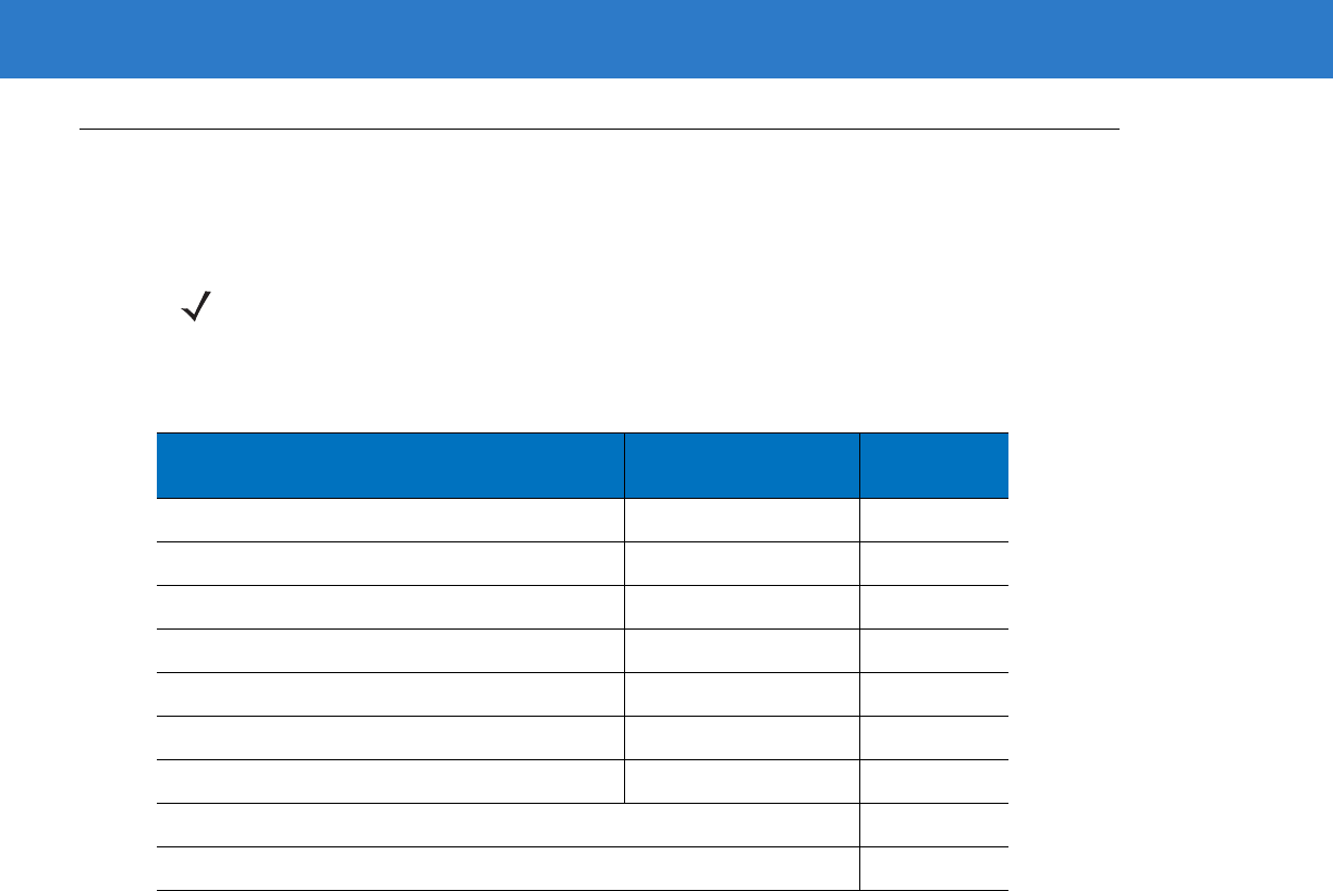
13 - 2 Symbol LS4208 Product Reference Guide
Miscellaneous Parameter Defaults
Table 13-1 lists the defaults for miscellaneous scanner options parameters. If you wish to change any option, scan
the appropriate bar code(s) provided in the Miscellaneous Scanner Parameters section beginning on page 13-3.
NOTE See Appendix A, Standard Default Parameters for all user preferences, hosts, symbologies, and
miscellaneous default parameters.
Table 13-1
Miscellaneous Scanner Options Default Table
Parameter Default Page
Number
Transmit Code ID Character None 13-3
Prefix Value 7013 <CR><LF> 13-3
Suffix Value 7013 <CR><LF> 13-3
Scan Data Transmission Format Data as is 13-4
FN1 Substitution Values Set 13-6
Transmit “No Read” Message Disable 13-6
Synapse Interface Standard 13-7
Report Version 13-8
Report Synapse Cable 13-8
Miscellaneous Scanner Options 13 - 3
Miscellaneous Scanner Parameters
Transmit Code ID Character
A Code ID character identifies the code type of a scanned bar code. This may be useful when the scanner is
decoding more than one code type. In addition to any single character prefix already selected, the Code ID
character is inserted between the prefix and the decoded symbol.
Select no Code ID character, a Symbol Code ID character, or an AIM Code ID character. For Code ID Characters,
see Symbol Code Identifiers on page B-1 and AIM Code Identifiers on page B-2.
Prefix/Suffix Values
A prefix and/or one or two suffixes can be appended to scan data for use in data editing. To set a value for a prefix
or suffix, scan a four-digit number (i.e., four bar codes from Appendix D, Numeric Bar Codes) that corresponds to
that value. See Table E-1 on page E-1 for the four-digit codes.
When using host commands to set the prefix or suffix, set the key category parameter to 1, then set the 3-digit
decimal value. See Table E-1 on page E-1 for the four-digit codes.
To correct an error or change a selection, scan Cancel on page D-3.
Symbol Code ID Character
AIM Code ID Character
*None
NOTE To use Prefix/Suffix values, first set the Scan Data Transmission Format on page 13-4.

13 - 4 Symbol LS4208 Product Reference Guide
Prefix/Suffix Values (continued)
Scan Data Transmission Format
To change the scan data format, scan Scan Options and one of the following four bar codes corresponding to the
desired format:
•
Data As Is
•
<DATA> <SUFFIX>
•
<PREFIX> <DATA>
•
<PREFIX> <DATA> <SUFFIX>.
Scan Enter on page 13-5 to complete the change. To set values for the prefix and/or suffix, see Prefix/Suffix
Values on page 13-3. Scan Data Format Cancel on page 13-5 to cancel the change.
If a carriage return/enter is required after each scanned bar code, scan the following bar codes in order:
1. Scan Options
2. <DATA> <SUFFIX>
3. Enter (on page 13-5).
Scan Prefix
Scan Suffix
Miscellaneous Scanner Options 13 - 5
Scan Data Transmission Format (continued)
Scan Options
*Data As Is
<DATA> <SUFFIX>
<PREFIX> <DATA>
<PREFIX> <DATA> <SUFFIX>
Enter
Data Format Cancel
13 - 6 Symbol LS4208 Product Reference Guide
FN1 Substitution Values
The Wedge and USB HID Keyboard hosts support an FN1 substitution feature. When enabled any FN1 character
(0x1b) in a GS1-128 bar code is substituted with a value. This value defaults to 7013 (Enter Key).
To select an FN1 substitution value via bar code menus:
1. Scan the bar code below.
2. Look up the keystroke desired for FN1 Substitution in the ASCII Value Standard Default Parameters Table on
page E-1 for the currently installed host interface.
3. Enter the 4-digit substitution value by scanning each digit in Appendix D, Numeric Bar Codes.
To correct an error or change the selection, scan Cancel.
To enable FN1 substitution for keyboard wedge, scan the Enable FN1 Substitution bar code on page 5-11.
To enable FN1 Substitution for USB HID keyboard, scan the Enable FN1 Substitution bar code on page 7-10.
Transmit “No Read” Message
Scan a bar code below to select whether or not to transmit a No Read message. When enabled, the characters NR
are transmitted when a bar code is not decoded. When disabled, if a symbol does not decode, nothing is sent to
the host.
*Set FN1 Substitution Value
Enable No Read
*Disable No Read

Miscellaneous Scanner Options 13 - 7
Synapse Interface
The auto-detection of a Synapse cable varies in duration depending on the type of Synapse connection. If a
scanner is connected to another scanner using a Synapse cable, use the Auxiliary Synapse Port connection. In all
other cases, where the cable is used, the default setting is recommended.
To disconnect and reconnect the scanner from a Synapse cable that is connected to a live host via a Synapse, use
the "Plug and Play" setting. Do not change this setting from the default if an on-board wedge host is enabled.
*Standard Synapse Connection
Auxiliary Synapse Port Connection
“Plug and Play” Synapse Connection

13 - 8 Symbol LS4208 Product Reference Guide
Report Version
Scan the bar code below to report the software revision installed in the scanner’s primary microprocessor.
Report Synapse Cable
Scan the bar code below to report the software revision of the attached Synapse cable. If the scanner does not
detect an attached Synapse cable, it reports Synapse not attached.
Report Software Version
Report Synapse Cable

Chapter 14 Advanced Data Formatting
Introduction
Advanced Data Formatting (ADF) is a means of customizing data before transmission to the host device. Edit scan
data to suit particular requirements.
To implement ADF, scan a related series of bar codes, which begin on page 14-8, or install the 123Scan utility (see
Chapter 11, 123Scan) which programs the scanner with ADF rules.
Rules: Criteria Linked to Actions
ADF uses rules to customize data. These rules perform detailed actions when the data meets certain criteria. One
rule may consist of single or multiple criteria applied to single or multiple actions.
For instance, a data formatting rule could be:
Criteria: When scan data is Code 39, length 12, and data at the start position is the string “129”,
Actions: pad all sends with zeros to length 8,
send all data up to X,
send a space.
Scanning a Code 39 bar code of 1299X1559828 transmits the following: 00001299<space>. If you scan a Code 39
bar code of 1299X15598, this rule is ignored because the bar code did not meet the length criteria.
The rule specifies the editing conditions and requirements before data transmission occurs.
NOTE If using the wand interface with the scanner, you cannot use ADF rules to format data.

14 - 2 Symbol LS4208 Product Reference Guide
Using ADF Bar Codes
When programming a rule, make sure the rule is logically correct. Plan ahead before you start scanning.
To program each data formatting rule:
•
Start the Rule. Scan the Begin New Rule bar code on page 14-8.
•
Criteria. Scan the bar codes for all pertinent criteria. Criteria can include code type (e.g., Code 128), code
length, or data that contains a specific character string (e.g., the digits “129”). See Criteria on page 14-11.
•
Actions. Scan all actions related to, or affecting, these criteria. The actions of a rule specify how to format
the data for transmission. See Actions on page 14-23.
•
Save the Rule. Scan the Save Rule bar code on page 14-8. This places the rule in the “top” position in the
rule buffer.
•
To correct errors during this process, erase criteria, actions, and entire rules by scanning the appropriate bar
code under Erase on page 14-9.
Beeper Definitions on page 2-2 guide through the programming steps. For more information on scanning, see
Chapter 2, Scanning.
ADF Bar Code Menu Example
This section provides an example of how to enter ADF rules for scan data.
An auto parts distribution center wants to encode manufacturer ID, part number, and destination code into their
own Code 128 bar codes. The distribution center also has products that carry UPC bar codes, placed there by the
manufacturer. The Code 128 bar codes have the following format:
MMMMMPPPPPDD
Where: M = Manufacturer ID
P = Part Number
D = Destination Code
The distribution center uses a PC with dedicated control characters for manufacturer ID <CTRL M>, part number
<CTRL P>, and destination code <CTRL D>. At this center the UPC data is treated as manufacturer ID code.
The following rules must be entered:
When scanning data of code type Code 128, send the next 5 characters, send the manufacturer ID key <CTRL
M>, send the next 5 characters, send the part number key <CTRL P>, send the next 2 characters, send the
destination code key <CTRL D>.
When scanning data of code type UPC/EAN, send all data, send the manufacturer ID key <CTRL M>.
To enter these rules, use the following steps:

Advanced Data Formatting 14 - 3
Rule 1: The Code 128 Scanning Rule
Step Bar Code On Page Beep Indication
1 Begin New Rule 14-8 High High
2 Code 128 14-11 High High
3 Send next 5 characters 14-23 High High
4 Send <CTRL M> 14-44 High High
5 Send next 5 characters 14-23 High High
6 Send <CTRL P> 14-45 High High
7 Send next 2 characters 14-23 High High
8 Send <CTRL D> 14-43 High High
9 Save Rule 14-8 High Low High Low
Rule 2: The UPC Scanning Rule
Step Bar Code On Page Beep Indication
1 Begin New Rule 14-8 High High
2 UPC/EAN 14-12 High High
3 Send all remaining data 14-23 High High
4 Send <CTRL M> 14-44 High High
5 Save Rule 14-8 High Low High Low
To correct any errors made while entering this rule, scan Quit Entering Rules on page 14-9. If you already saved
the rule, scan Erase Previously Saved Rule on page 14-9.
Alternate Rule Sets
Group ADF rules into one of four alternate sets which you can turn on and off when needed. This is useful to format
the same message in different ways. For example, a Code 128 bar code contains the following information:
Class (2 digits), Stock Number (8) digits, Price (5 digits)
This bar code might look like this:
245671243701500
where:
Class = 24
Stock Number = 56712437
Price = 01500
Ordinarily this data transmits as follows:
24 (class key)
56712437 (stock key)
01500 (enter key)

14 - 4 Symbol LS4208 Product Reference Guide
But, when there is a sale, send only the following:
24 (class key)
56712437 (stock key)
and the cashier keys the price manually.
To implement this, first enter an ADF rule that applies to the normal situation, such as:
When scanning a bar code of length 15, send the next 2 characters, send the class key, send the next 8
characters, send the stock key, send the data that remains, send the Enter key.
The “sale” rule may look like this:
When scanning a bar code of length 15, send the next 2 characters, send the class key, send the next 8
characters, send the stock key.
To switch between the two sets of rules, program a “switching rule” that specifies the type of bar code to scan to
switch between the rule sets. For example, in the case of the “sale” rule above, the rule programmer wants the
cashier to scan the bar code “M” before a sale. To do this, enter the following rule:
When scanning a bar code of length 1 that begins with “M”, select rule set number 1.
Program another rule to switch back:
When scanning a bar code of length 1 that begins with “N”, turn off rule set number 1.
Or include the switching back to normal rules in the “sale” rule:
When scanning a bar code of length 15, send the next 2 characters, send the class key, send the next 8
characters, send the stock key, turn off rule set 1.
For optimal results, scan Disable All Rule Sets on page 14-10 after programming a rule belonging to an alternate
rule set.
In addition to enabling and disabling rule sets within the rules, enable or disable them by scanning the appropriate
bar codes beginning on page 14-10.
Rules Hierarchy (in Bar Codes)
The order of programming individual rules is important. Program the most general rule first.
All programmed rules are stored in a buffer. As they are programmed, they are stored at the “top” of a rules list. If
you created three rules, the list is configured as follows:
Third Rule
Second Rule
First Rule
When scanning data, the rules list is checked from top to bottom to determine if the criteria match (and therefore, if
the actions occur). Input is modified into the data format specified by the first matching set of criteria it finds. Be
sure to program the most general rule first.
For example, if the THIRD rule states:
When scanning a bar code of any length, send all data, then send the ENTER key.

Advanced Data Formatting 14 - 5
And the SECOND rule states:
When scanning a Code 128 bar code of length 12, send the first four characters, then send the ENTER key,
then send all remaining data.
and you scan a Code 128 bar code of length 12, the THIRD rule applies, and the SECOND rule does not function.
Note that using the standard data editing functions also creates ADF rules. Scan options are entered as ADF rules,
and the hierarchy mentioned above also applies to them. For the Symbol LS4208, this applies to prefix/suffix
programming in Scan Data Transmission Format on page 13-4.
These rules reside in the same “rule list” as ADF rules, so the order of their creation is also important.
Default Rules
Every unit has a default rule to send all scan data. Units with custom software may have one or more default rules
burned in. The rules hierarchy checks user programmable rules first, then the default rules. Disable default rules by
entering the following general rule in the user programmable buffer:
When receiving scan data, send all data.
Since this rule always applies, ADF never enters the default rules.
ADF Bar Codes
Table 14-1 lists the bar codes available through ADF.
Table 14-1
ADF Bar Codes
Parameter Page
Number
Special Commands 14-8
Pause Duration 14-8
Begin New Rule 14-8
Save Rule 14-8
Erase 14-9
Quit Entering Rules 14-9
Disable Rule Set 14-10
Criteria 14-11
Code Types 14-11
Code Lengths 14-15
1 Character
-
7 Characters 14-15
8 Characters
-
14 Characters 14-16
15 Characters
-
22 Characters 14-17
23 Characters
-
30 Characters 14-18

14 - 6 Symbol LS4208 Product Reference Guide
Specific String At Start 14-19
Specific String Any Location 14-20
Specific String Search 14-20
Any Message OK 14-20
Numeric Keypad 14-21
Rule Belongs To Set 14-22
Actions 14-23
Send Data 14-23
Send Data Up To Character
14-23
Send Next Character
14-23
Send All Data That Remains
14-23
Send Next 2 Characters
-
Send Next 20 Characters 14-23
Move Cursor 14-27
Send Pause 14-28
Skip Ahead 14-29
Skip Back 14-31
Send Preset Value 14-32
Remove All Spaces 14-33
Crunch All Spaces 14-33
Stop Space Removal 14-33
Remove Leading Zeros 14-33
Stop Zero Removal 14-33
Pad Data with Spaces 14-34
Pad Data with Zeros 14-38
Beeps 14-42
Send Keystroke (Control Characters and Keyboard Characters) 14-43
Keyboard Characters 14-47
Send ALT Characters 14-59
Send Keypad Characters 14-63
Send Function Key 14-68
Table 14-1
ADF Bar Codes (Continued)
Parameter Page
Number

Advanced Data Formatting 14 - 7
Send F1 Key
-
Send F24 Key 14-68
Send PF1 Key
-
Send PF30 Key 14-71
Send Right Control Key 14-75
Send Graphic User Interface (GUI) Characters 14-76
Send GUI 0
-
Send GUI 9 14-76
Send GUI A
-
Send GUI Z 14-77
Turn On/Off Rule Sets 14-82
Alphanumeric Keyboard 14-83
Space
-
‘ 14-83
0
-
9 14-87
A
-
Z 14-88
Cancel 14-91
End of Message 14-91
a
-
z 14-92
{
-
~ 14-95
Table 14-1
ADF Bar Codes (Continued)
Parameter Page
Number

14 - 8 Symbol LS4208 Product Reference Guide
Special Commands
Pause Duration
This parameter, along with Send Pause on page 14-28, inserts a pause in the data transmission. To set the pause
scan a two-digit number (i.e., two bar codes) representing a 0.1 second interval in the range of 0.1 to 9.9. For
example, scanning bar codes 0 and 1 inserts a 0.1 second pause; 0 and 5 gives a 0.5 second delay. The default is
1 second. For numeric bar codes see Appendix D, Numeric Bar Codes. In case of an error, or to change the
selection, scan Cancel on page D-3.
Pause Duration
Begin New Rule
Scan this bar code to start entering a new rule
Begin New Rule
Save Rule
Scan this bar code to save the rule.
Save Rule
Advanced Data Formatting 14 - 9
Erase
Use these bar codes to erase criteria, actions, or rules.
Quit Entering Rules
Scan this bar code to quit entering rules.
Quit Entering Rules
Erase Criteria And Start Again
Erase Actions And Start Again
Erase Previously Saved Rule
Erase All Rules
14 - 10 Symbol LS4208 Product Reference Guide
Disable Rule Set
Use these bar codes to disable rule sets.
Disable Rule Set 1
Disable Rule Set 2
Disable Rule Set 3
Disable Rule Set 4
Disable All Rule Sets
Advanced Data Formatting 14 - 11
Criteria
Code Types
Select any number of code types to be affected by the rule. Scan all selected codes in succession, prior to
selecting other criteria. To select all code types, do not scan any code type.
Code 39
Codabar
GS1 DataBar-14
GS1 DataBar Limited
GS1 DataBar Expanded
Code 128
14 - 12 Symbol LS4208 Product Reference Guide
Code Types (continued)
D 2 OF 5
IATA 2 OF 5
I 2 OF 5
Code 93
UPC-A
UPC-E
EAN-8
EAN-13
Advanced Data Formatting 14 - 13
Code Types (continued)
MSI
GS1-128
UPC-E1
Bookland EAN
Trioptic Code 39
Code 11

14 - 14 Symbol LS4208 Product Reference Guide
Code Types (continued)
PDF417
MicroPDF
UPC/EAN Composites
GS1 DataBar and GS1-128 Composites
Advanced Data Formatting 14 - 15
Code Lengths
Scan these bar codes to define the number of characters the selected code type must contain. Select one length
per rule only. Do not select any code length to select code types of any length.
1 Character
2 Characters
3 Characters
4 Characters
5 Characters
6 Characters
7 Characters
14 - 16 Symbol LS4208 Product Reference Guide
Code Lengths (continued)
8 Characters
9 Characters
10 Characters
11 Characters
12 Characters
13 Characters
14 Characters
Advanced Data Formatting 14 - 17
Code Lengths (continued)
15 Characters
16 Characters
17 Characters
18 Characters
19 Characters
20 Characters
21 Characters
22 Characters

14 - 18 Symbol LS4208 Product Reference Guide
Code Lengths (continued)
23 Characters
24 Characters
25 Characters
26 Characters
27 Characters
28 Characters
29 Characters
30 Characters

Advanced Data Formatting 14 - 19
Message Containing A Specific Data String
Use this feature to select whether the formatting affects data that begins with a specific character or data string, or
contains a specific character or data string.
There are five features:
•
Specific String at Start
•
Specific String, Any Location
•
Specific String Search
•
Any Message OK
•
Rule Belongs to Set
Specific String at Start
1. Scan the following bar code.
2. Scan the bar codes representing the desired character or characters (up to a total of 8) using the Alphanumeric
Keyboard on page 14-83.
3. Scan End of Message on page 14-91.
Specific String At Start
Specific String, Any Location
1. Scan the following bar code.
2. Enter a location by scanning a two-digit number representing the position (use a leading “zero” if necessary)
using the Numeric Keypad on page 14-21.
3. Scan the bar codes representing the desired character or characters (up to a total of 8) using the Alphanumeric
Keyboard on page 14-83.
4. Scan End of Message on page 14-91.
Specific String Any Location

14 - 20 Symbol LS4208 Product Reference Guide
Specific String Search
1. Scan the following bar code.
2. Scan the bar codes representing the desired character or characters (up to a total of 10) using the
Alphanumeric Keyboard on page 14-83.
3. Scan End of Message on page 14-91.
Any Message OK
Do not scan any bar code to format all selected code types, regardless of information contained.
Specific String Search

Advanced Data Formatting 14 - 21
Numeric Keypad
Bar codes on this page should not be confused with those on the alphanumeric keyboard.
0
1
2
3
4
5
6
7
14 - 22 Symbol LS4208 Product Reference Guide
Numeric Keypad (continued)
Rule Belongs To Set
Select the set a rule belongs to. (There are four possible rule sets.) See Alternate Rule Sets on page 14-3 for more
information about rule sets.
Scan a bar code below to select which set a rule belongs to.
8
9
Cancel
Rule Belongs To Set 1
Rule Belongs To Set 2
Rule Belongs To Set 3
Rule Belongs To Set 4
Advanced Data Formatting 14 - 23
Actions
Select how to format the data for transmission.
Send Data
Send all data that remains, send all data up to a specific character selected from the Alphanumeric Keyboard on
page 14-83, or send the next N characters. N = any number from 1 to 254, selected from the Alphanumeric
Keyboard on page 14-83. Use these bar codes to send data.
Send Data Up To Character
Send All Data That Remains
Send Next Character
Send Next 2 Characters
Send Next 3 Characters
Send Next 4 Characters
Send Next 5 Characters
14 - 24 Symbol LS4208 Product Reference Guide
Send Data (continued)
Send Next 6 Characters
Send Next 7 Characters
Send Next 8 Characters
Send Next 9 Characters
Send Next 10 Characters
Send Next 11 Characters
Send Next 12 Characters
Send Next 13 Characters
Advanced Data Formatting 14 - 25
Send Data (continued)
Send Next 14 Characters
Send Next 15 Characters
Send Next 16 Characters
Send Next 17 Characters
Send Next 18 Characters
Send Next 19 Characters
Send Next 20 Characters
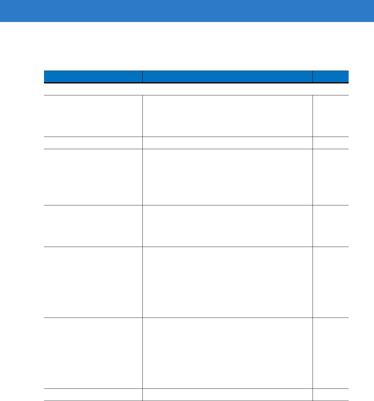
14 - 26 Symbol LS4208 Product Reference Guide
Setup Field(s)
Table 14-2
Setup Field(s) Definitions
Parameter Description Page
Move Cursor
Move Cursor to a Character Scan the
Move Cursor To Character bar code on page 14-27
,
then any printable ASCII character from the
Alphanumeric
Keyboard
. When this is used, the cursor moves to the position
after the matching character. If the character is not there, the
rule fails and ADF tries the next rule.
14-27
Move Cursor to Start of Data Scan this bar code to move cursor to the beginning of the data. 14-27
Move Cursor Past a Character This parameter moves the cursor past all sequential
occurrences of a selected character. For example, if the
selected character is ‘A,’ then the cursor moves past ‘A,’ ‘AA,’
‘AAA,’ etc. Scan the
Move Cursor Past Character bar code on
page 14-27
, then select a character from the
Alphanumeric
Keyboard
. If the character is not there, the cursor does not
move (i.e., has no effect).
14-27
Move Cursor Past a Specific String This action moves the cursor past the first occurrence of a
selected string. Scan
Move Cursor Past Specific String
, then
select the character(s) (up to 10) using the
Alphanumeric
Keyboard
. Scan the
Move Cursor Past Character bar code
on page 14-27
.
14-27
Move Cursor to Specific String and
Replace This action moves the cursor to the first occurrence of a
selected string and replaces the string with another
user-defined string. Scan
Move Cursor to Specific String and
Replace
, then enter an alphanumeric string representing the
character(s) (up to 10) to match and delete using the
Alphanumeric Keyboard
. Scan the
End of Message
. Enter
another alphanumeric string representing the character(s) (up
to 10) to insert using the
Alphanumeric Keyboard
. Scan
End
of Message
.
14-28
Move Cursor to Last Occurrence of
String and Replace All This action replaces all occurrences of a selected string with
another user-defined string, and moves the cursor to the
beginning of the last occurrence. Scan
Move Cursor to Last
Occurrence of String and Replace All
, then enter an
alphanumeric string representing the character(s) (up to 10) to
match and delete using the
Alphanumeric Keyboard
. Scan the
End of Message
. Enter another alphanumeric string
representing the character(s) (up to 10) to insert using the
Alphanumeric Keyboard
. Scan
End of Message
.
14-28
Skip to End Scan
Skip to End
to move the cursor to the end of the data.
14-28
Advanced Data Formatting 14 - 27
Move Cursor
Scan a bar code below to move the cursor in relation to a specified character. Then enter a character by scanning
a bar code from the Alphanumeric Keyboard on page 14-83.
Skip Ahead “N” Characters Scan one of these bar codes to select the desired number of
positions to move the cursor ahead. 14-29
Skip Back “N” Characters Scan one of these bar codes to select the desired number of
positions to move the cursor back. 14-31
Send Preset Value Send prefix and/or suffix value by scanning the appropriate bar
code. These values must be set using the Scan Prefix and
Scan Suffix bar codes on page 13-4.
14-32
Table 14-2
Setup Field(s) Definitions (Continued)
Parameter Description Page
NOTE If there is no match when the rule is interpreted and the rule fails, the next rule is checked.
Move Cursor To Character
Move Cursor To Start
Move Cursor Past Character
Move Cursor Past Specific String

14 - 28 Symbol LS4208 Product Reference Guide
Move Cursor (continued)
Send Pause
Scan the bar code below to insert a pause in the transmission of data. The length of this pause is controlled by the
value of the Pause Duration parameter.
Send Pause
Move Cursor to
Specific String and Replace
Move Cursor to Last Occurrence
of String and Replace All
Skip to End

Advanced Data Formatting 14 - 29
Skip Ahead
Use the following bar codes to skip ahead characters.
Skip Ahead 1 Character
Skip Ahead 2 Characters
Skip Ahead 3 Characters
Skip Ahead 4 Characters
Skip Ahead 5 Characters
Skip Ahead 6 Characters

14 - 30 Symbol LS4208 Product Reference Guide
Skip Ahead (continued)
Skip Ahead 7 Characters
Skip Ahead 8 Characters
Skip Ahead 9 Characters
Skip Ahead 10 Characters
Advanced Data Formatting 14 - 31
Skip Back
Use the following bar codes to skip back characters.
Skip Back 1 Character
Skip Back 2 Characters
Skip Back 3 Characters
Skip Back 4 Characters
Skip Back 5 Characters
Skip Back 6 Characters
Skip Back 7 Characters
14 - 32 Symbol LS4208 Product Reference Guide
Skip Back (continued)
Send Preset Value
Use these bar codes to send preset values. These values must be set using the Scan Prefix and Scan Suffix bar
codes on page 13-4.
Skip Back 8 Characters
Skip Back 9 Characters
Skip Back 10 Characters
Send Prefix
Send Suffix
Advanced Data Formatting 14 - 33
Modify Data
Modify data in the ways listed. The following actions work for all send commands that follow it within a rule. If pad
zeros to length 6, send next 3 characters, stop padding, send next 5 characters is programmed, three zeros are
added to the first send, and the next send is unaffected by the padding. These options do not apply to the Send
Keystroke or Send Preset Value options.
Remove All Spaces
To remove all spaces in the send commands that follow, scan this bar code.
Remove All Spaces
Crunch All Spaces
To leave one space between words, scan this bar code. This also removes all leading and trailing spaces.
Crunch All Spaces
Stop Space Removal
Scan this bar code to disable space removal.
Stop Space Removal
Remove Leading Zeros
Scan this bar code to remove all leading zeros.
Remove Leading Zeros
Stop Zero Removal
Scan this bar code to disable the removal of zeros.
Stop Zero Removal
14 - 34 Symbol LS4208 Product Reference Guide
Pad Data with Spaces
To pad data to the left, scan the bar code containing the desired number of spaces. This parameter is activated by
Send commands.
Pad Spaces To Length 1
Pad Spaces To Length 2
Pad Spaces To Length 3
Pad Spaces To Length 4
Pad Spaces To Length 5
Pad Spaces To Length 6
Pad Spaces To Length 7
Pad Spaces To Length 8
Advanced Data Formatting 14 - 35
Pad Data with Spaces (continued)
Pad Spaces To Length 9
Pad Spaces To Length 10
Pad Spaces To Length 11
Pad Spaces To Length 12
Pad Spaces To Length 13
Pad Spaces To Length 14
Pad Spaces To Length 15
Pad Spaces To Length 16
14 - 36 Symbol LS4208 Product Reference Guide
Pad Data with Spaces (continued)
Pad Spaces To Length 17
Pad Spaces To Length 18
Pad Spaces To Length 19
Pad Spaces To Length 20
Pad Spaces To Length 21
Pad Spaces To Length 22
Pad Spaces To Length 23
Advanced Data Formatting 14 - 37
Pad Data with Spaces (continued)
Pad Spaces To Length 24
Pad Spaces To Length 25
Pad Spaces To Length 26
Pad Spaces To Length 27
Pad Spaces To Length 28
Pad Spaces To Length 29
Pad Spaces To Length 30
Stop Pad Spaces
14 - 38 Symbol LS4208 Product Reference Guide
Pad Data with Zeros
To pad data to the left, scan the bar code containing the desired number of zeros. This parameter is activated by
Send commands.
Pad Zeros To Length 1
Pad Zeros To Length 2
Pad Zeros To Length 3
Pad Zeros To Length 4
Pad Zeros To Length 5
Pad Zeros To Length 6
Pad Zeros To Length 7
Pad Zeros To Length 8
Advanced Data Formatting 14 - 39
Pad Data with Zeros (continued)
Pad Zeros To Length 9
Pad Zeros To Length 10
Pad Zeros To Length 11
Pad Zeros To Length 12
Pad Zeros To Length 13
Pad Zeros To Length 14
Pad Zeros To Length 15
Pad Zeros To Length 16
14 - 40 Symbol LS4208 Product Reference Guide
Pad Data with Zeros (continued)
Pad Zeros To Length 17
Pad Zeros To Length 18
Pad Zeros To Length 19
Pad Zeros To Length 20
Pad Zeros To Length 21
Pad Zeros To Length 22
Pad Zeros To Length 23
Pad Zeros To Length 24
Advanced Data Formatting 14 - 41
Pad Data with Zeros (continued)
Pad Zeros To Length 25
Pad Zeros To Length 26
Pad Zeros To Length 27
Pad Zeros To Length 28
Pad Zeros To Length 29
Pad Zeros To Length 30
Stop Pad Zeros

14 - 42 Symbol LS4208 Product Reference Guide
Beeps
Select a beep sequence for each ADF rule.
Beep Once
Beep Twice
Beep Three Times
Advanced Data Formatting 14 - 43
Send Keystroke (Control Characters and Keyboard Characters)
Control Characters
Scan the “Send __” bar code for the desired keystroke
Send Control 2
Send Control A
Send Control B
Send Control C
Send Control D
Send Control E
Send Control F
Send Control G

14 - 44 Symbol LS4208 Product Reference Guide
Control Characters (continued)
Send Control H
Send Control I
Send Control J
Send Control K
Send Control L
Send Control M
Send Control N
Send Control O
Advanced Data Formatting 14 - 45
Control Characters (continued)
Send Control P
Send Control Q
Send Control R
Send Control S
Send Control T
Send Control U
Send Control V
Send Control W
14 - 46 Symbol LS4208 Product Reference Guide
Control Characters (continued)
Send Control X
Send Control Y
Send Control Z
Send Control [
Send Control \
Send Control ]
Send Control 6
Send Control -

Advanced Data Formatting 14 - 47
Keyboard Characters
Scan the “Send __” bar code for the desired keyboard characters
Send Space
Send !
Send “
Send #
Send $
Send %
Send &
Send ‘

14 - 48 Symbol LS4208 Product Reference Guide
Keyboard Characters (continued)
Send (
Send )
Send *
Send +
Send ,
Send -
Send .
Send /

Advanced Data Formatting 14 - 49
Keyboard Characters (continued)
Send 0
Send 1
Send 2
Send 3
Send 4
Send 5
Send 6
Send 7

14 - 50 Symbol LS4208 Product Reference Guide
Keyboard Characters (continued)
Send 8
Send 9
Send :
Send ;
Send <
Send =
Send >
Send ?
Advanced Data Formatting 14 - 51
Keyboard Characters (continued)
Send @
Send A
Send B
Send C
Send D
Send E
Send F
Send G

14 - 52 Symbol LS4208 Product Reference Guide
Keyboard Characters (continued)
Send H
Send I
Send J
Send K
Send L
Send M
Send N
Send O

Advanced Data Formatting 14 - 53
Keyboard Characters (continued)
Send P
Send Q
Send R
Send S
Send T
Send U
Send V
Send W
14 - 54 Symbol LS4208 Product Reference Guide
Keyboard Characters (continued)
Send X
Send Y
Send Z
Send [
Send \
Send ]
Send ^
Send _
Advanced Data Formatting 14 - 55
Keyboard Characters (continued)
Send `
Send a
Send b
Send c
Send d
Send e
Send f
Send g

14 - 56 Symbol LS4208 Product Reference Guide
Keyboard Characters (continued)
Send h
Send i
Send j
Send k
Send l
Send m
Send n
Send o
Advanced Data Formatting 14 - 57
Keyboard Characters (continued)
Send p
Send q
Send r
Send s
Send t
Send u
Send v
Send w
14 - 58 Symbol LS4208 Product Reference Guide
Keyboard Characters (continued)
Send x
Send y
Send z
Send {
Send |
Send }
Send ~

Advanced Data Formatting 14 - 59
Send ALT Characters
Send Alt 2
Send Alt A
Send Alt B
Send Alt C
Send Alt D
Send Alt E
Send Alt F
Send Alt G

14 - 60 Symbol LS4208 Product Reference Guide
Send ALT Characters (continued)
Send Alt H
Send Alt I
Send Alt J
Send Alt K
Send Alt L
Send Alt M
Send Alt N
Send Alt O

Advanced Data Formatting 14 - 61
Send ALT Characters (continued)
Send Alt P
Send Alt Q
Send Alt R
Send Alt S
Send Alt T
Send Alt U
Send Alt V
Send Alt W
14 - 62 Symbol LS4208 Product Reference Guide
Send ALT Characters (continued)
Send Alt X
Send Alt Y
Send Alt Z
Send Alt [
Send Alt \
Send Alt ]
Send Alt 6
Send Alt -
Advanced Data Formatting 14 - 63
Send Keypad Characters
Send Keypad *
Send Keypad +
Send Keypad -
Send Keypad .
Send Keypad /
Send Keypad 0
Send Keypad 1
Send Keypad 2
14 - 64 Symbol LS4208 Product Reference Guide
Send Keypad Characters (continued)
Send Keypad 3
Send Keypad 4
Send Keypad 5
Send Keypad 6
Send Keypad 7
Send Keypad 8
Send Keypad 9
Send Keypad Enter
Advanced Data Formatting 14 - 65
Send Keypad Characters (continued)
Send Keypad Numlock
NUM LOCK
Send Break Key
Send Delete Key
Send Page Up Key
Send End Key
Send Page Down Key
Send Pause Key
Send Scroll Lock Key
14 - 66 Symbol LS4208 Product Reference Guide
Send Keypad Characters (continued)
Send Backspace Key
Send Tab Key
Send Print Screen Key
Send Insert Key
Send Home Key
Send Enter Key
Send Escape Key
Send Up Arrow Key

Advanced Data Formatting 14 - 67
Send Keypad Characters (continued)
Send Down Arrow Key
Send Left Arrow Key
Send Right Arrow Key
14 - 68 Symbol LS4208 Product Reference Guide
Send Function Key
Send F1 Key
Send F2 Key
Send F3 Key
Send F4 Key
Send F5 Key
Send F6 Key

Advanced Data Formatting 14 - 69
Send Function Key (continued)
Send F7 Key
Send F8 Key
Send F9 Key
Send F10 Key
Send F11 Key
Send F12 Key
Send F13 Key
Send F14 Key

14 - 70 Symbol LS4208 Product Reference Guide
Send Function Key (continued)
Send F15 Key
Send F16 Key
Send F17 Key
Send F18 Key
Send F19 Key
Send F20 Key
Send F21 Key
Send F22 Key
Advanced Data Formatting 14 - 71
Send Function Key (continued)
Send F23 Key
Send F24 Key
Send PF1 Key
Send PF2 Key
Send PF3 Key
Send PF4 Key
Send PF5 Key
Send PF6 Key
14 - 72 Symbol LS4208 Product Reference Guide
Send Function Key (continued)
Send PF7 Key
Send PF8 Key
Send PF9 Key
Send PF10 Key
Send PF11 Key
Send PF12 Key
Send PF13 Key
Send PF14 Key

Advanced Data Formatting 14 - 73
Send Function Key (continued)
Send PF15 Key
Send PF16 Key
Send PF17 Key
Send PF18 Key
Send PF19 Key
Send PF20 Key
Send PF21 Key
Send PF22 Key
14 - 74 Symbol LS4208 Product Reference Guide
Send Function Key (continued)
Send PF23 Key
Send PF24 Key
Send PF25 Key
Send PF26 Key
Send PF27 Key
Send PF28 Key
Send PF29 Key
Send PF30 Key

Advanced Data Formatting 14 - 75
Send Right Control Key
The “Send Right Control Key” action sends a tap (press and release) of the Right Control Key.
Send Right Control Key
14 - 76 Symbol LS4208 Product Reference Guide
Send Graphic User Interface (GUI) Characters
The “Send Graphic User Interface Character” actions tap the specified key while holding the System Dependent
Graphic User Interface (GUI) Key. The definition of the Graphic User Interface key is dependent upon the attached
system:
Send GUI 0
Send GUI 1
Send GUI 2
Send GUI 3
Send GUI 4
Send GUI 5
Advanced Data Formatting 14 - 77
Send Graphic User Interface (GUI) Characters (continued)
Send GUI 6
Send GUI 7
Send GUI 8
Send GUI 9
Send GUI A
Send GUI B
Send GUI C
14 - 78 Symbol LS4208 Product Reference Guide
Send Graphic User Interface (GUI) Characters (continued)
Send GUI D
Send GUI E
Send GUI F
Send GUI G
Send GUI H
Send GUI I
Send GUI J
Advanced Data Formatting 14 - 79
Send Graphic User Interface (GUI) Characters (continued)
Send GUI K
Send GUI L
Send GUI M
Send GUI N
Send GUI O
Send GUI P
Send GUI Q
14 - 80 Symbol LS4208 Product Reference Guide
Send Graphic User Interface (GUI) Characters (continued)
Send GUI R
Send GUI S
Send GUI T
Send GUI U
Send GUI V
Send GUI W
Send GUI X

Advanced Data Formatting 14 - 81
Send Graphic User Interface (GUI) Characters (continued)
Send GUI Y
Send GUI Z

14 - 82 Symbol LS4208 Product Reference Guide
Turn On/Off Rule Sets
Use these bar codes to turn rule sets on and off.
Turn On Rule Set 1
Turn On Rule Set 2
Turn On Rule Set 3
Turn On Rule Set 4
Turn Off Rule Set 1
Turn Off Rule Set 2
Turn Off Rule Set 3
Turn Off Rule Set 4
Advanced Data Formatting 14 - 83
Alphanumeric Keyboard
Space
#
$
%
*
+
-
(Dash)
.
,
(Comma)

14 - 84 Symbol LS4208 Product Reference Guide
Alphanumeric Keyboard (continued)
/
!
“
&
‘
(
)
Advanced Data Formatting 14 - 85
Alphanumeric Keyboard (continued)
:
;
<
=
>
?
@
14 - 86 Symbol LS4208 Product Reference Guide
Alphanumeric Keyboard (continued)
[
\
]
^
_
(Underscore)
`
(Single Open Quote)
Advanced Data Formatting 14 - 87
Alphanumeric Keyboard (continued)
NOTE Bar codes on this page should not be confused with those on the numeric keypad.
0
1
2
3
4
5
6
14 - 88 Symbol LS4208 Product Reference Guide
Alphanumeric Keyboard (continued)
7
8
9
A
B
C
D
Advanced Data Formatting 14 - 89
Alphanumeric Keyboard (continued)
E
F
G
H
I
J
K
L
14 - 90 Symbol LS4208 Product Reference Guide
Alphanumeric Keyboard (continued)
M
N
O
P
Q
R
S
T
Advanced Data Formatting 14 - 91
Alphanumeric Keyboard (continued)
U
V
W
X
Y
Z
Cancel
End of Message
14 - 92 Symbol LS4208 Product Reference Guide
Alphanumeric Keyboard (continued)
a
b
c
d
e
f
g
h
Advanced Data Formatting 14 - 93
Alphanumeric Keyboard (continued)
i
j
k
l
m
n
o
14 - 94 Symbol LS4208 Product Reference Guide
Alphanumeric Keyboard (continued)
p
q
r
s
t
u
v
Advanced Data Formatting 14 - 95
Alphanumeric Keyboard (continued)
w
x
y
z
{
|
}
~

14 - 96 Symbol LS4208 Product Reference Guide

Appendix A Standard Default Parameters
Default Parameters
Table A-1
Standard Default Parameters Table
Parameter Default Page
Number
User Preferences
Set Default Parameter Restore Defaults
4-3
Parameter Bar Code Scanning Enable
4-4
Beeper Tone Medium
4-4
Beeper Volume High
4-5
Power Mode Continuous On
4-5
Scan Pattern Multi-line Always Raster
4-6
Scan Line Width Full Width
4-7
Raster Height Adjustable Raster
4-8
Laser On Time 3.0 Sec
4-9
Beep After Good Decode Enable
4-9
PDF Decode Feedback Disable
4-10
Keyboard Wedge Host Parameters
Keyboard Wedge Host Type IBM PC/AT& IBM PC Compatibles
1
5-4
Country Types (Country Codes) North American
5-5
Ignore Unknown Characters Send
5-6
1
User selection is required to configure this interface and this is the most common selection.

A - 2 Symbol LS4208 Product Reference Guide
Keystroke Delay No Delay
5-7
Intra-Keystroke Delay Disable
5-7
Alternate Numeric Keypad Emulation Disable
5-8
Caps Lock On Disable
5-8
Caps Lock Override Disable
5-9
Convert Wedge Data No Convert
5-10
Function Key Mapping Disable
5-10
FN1 Substitution Disable
5-11
Send and Make Break Send
5-11
RS-232 Host Parameters
RS-232 Host Types Standard
6-6
Baud Rate 9600
6-7
Parity Type None
6-8
Stop Bit Select 1 Stop Bit
6-9
Data Bits (ASCII Format) 8-Bit
6-9
Check Receive Errors Enable
6-10
Hardware Handshaking None
6-10
Software Handshaking None
6-12
Host Serial Response Time-out 2 Sec
6-14
RTS Line State Low RTS
6-15
Beep on <BEL> Disable
6-15
Intercharacter Delay 0 msec
6-16
Nixdorf Beep/LED Options Normal Operation
6-17
Ignore Unknown Characters Send Bar Code
6-17
USB Host Parameters
USB Device Type HID Keyboard Emulation
7-5
USB Country Keyboard Types (Country Codes) North American
7-6
USB Keystroke Delay No Delay
7-8
Table A-1
Standard Default Parameters Table (Continued)
Parameter Default Page
Number
1
User selection is required to configure this interface and this is the most common selection.

Standard Default Parameters A - 3
USB CAPS Lock Override Disable
7-8
USB Ignore Unknown Characters Send
7-9
Emulate Keypad Disable
7-9
USB FN1 Substitution Disable
7-10
Function Key Mapping Disable
7-10
Simulated Caps Lock Disable
7-11
Convert Case No Case Conversion
7-11
IBM 468X/469X Host Parameters
Port Address None Selected
8-4
Convert Unknown to Code 39 Disable
8-5
Ignore Beep Disable
8-6
Ignore Bar Code Configuration Disable
8-6
Wand Emulation Host Parameters
Wand Emulation Host Types Symbol OmniLink Interface Controller
1
9-4
Leading Margin 80 msec
9-5
Polarity Bar High/Margin Low
9-6
Ignore Unknown Characters Send
9-6
Convert All Bar Codes to Code 39 Disable
9-7
Convert Code 39 to Full ASCII Disable
9-8
Scanner Emulation
Beep Style Beep on Successful Transmit
10-4
Parameter Pass-Through Parameter Process and Pass Through
10-5
Convert Newer Code Types Convert Newer Code Types
10-6
Module Width 20 µs
10-7
Convert All Bar Codes to Code 39 Do Not Convert Bar Codes to Code 39
10-7
Code 39 Full ASCII Conversion Disable
10-8
Transmission Timeout 3 Sec
10-9
Ignore Unknown Characters Ignore Unknown Characters
10-10
Table A-1
Standard Default Parameters Table (Continued)
Parameter Default Page
Number
1
User selection is required to configure this interface and this is the most common selection.
A - 4 Symbol LS4208 Product Reference Guide
Leading Margin 2 ms
10-10
Check for Decode LED Check for Decode LED
10-11
123Scan Configuration Tool
123Scan Configuration None
1
11-1
UPC/EAN
UPC-A Enable
12-6
UPC-E Enable
12-6
UPC-E1 Disable
12-7
EAN-8/JAN 8 Enable
12-8
EAN-13/JAN 13 Enable
12-8
Bookland EAN Disable
12-9
Decode UPC/EAN/JAN Supplementals
(2 and 5 digits) Ignore
12-9
Decode UPC/EAN/JAN Supplemental
Redundancy 7
12-14
Transmit UPC-A Check Digit Enable
12-14
Transmit UPC-E Check Digit Enable
12-15
Transmit UPC-E1 Check Digit Enable
12-15
UPC-A Preamble System Character
12-16
UPC-E Preamble System Character
12-17
UPC-E1 Preamble System Character
12-18
Convert UPC-E to A Disable
12-19
Convert UPC-E1 to A Disable
12-19
EAN-8/JAN-8 Extend Disable
12-20
Bookland ISBN Format ISBN-10
12-21
UCC Coupon Extended Code Disable
12-22
Table A-1
Standard Default Parameters Table (Continued)
Parameter Default Page
Number
1
User selection is required to configure this interface and this is the most common selection.
Standard Default Parameters A - 5
Code 128
Code 128 Enable
12-23
GS1-128 (formerly UCC/EAN-128) Enable
12-23
ISBT 128 (non-concatenated) Enable
12-24
Code 39
Code 39 Enable
12-25
Trioptic Code 39 Disable
12-25
Convert Code 39 to Code 32
(Italian Pharmacy Code) Disable
12-26
Code 32 Prefix Disable
12-26
Set Length(s) for Code 39 2 to 55
12-27
Code 39 Check Digit Verification Disable
12-28
Transmit Code 39 Check Digit Disable
12-29
Code 39 Full ASCII Conversion Disable
12-30
Buffer Code 39 Disable
12-31
Code 93
Code 93 Disable
12-34
Set Length(s) for Code 93 4 to 55
12-34
Code 11
Code 11 Disable
12-36
Set Lengths for Code 11 4 to 55
12-36
Code 11 Check Digit Verification Disable
12-38
Transmit Code 11 Check Digit(s) Disable
12-39
Interleaved 2 of 5 (ITF)
Interleaved 2 of 5 (ITF) Enable
12-40
Set Lengths for I 2 of 5 14
12-40
I 2 of 5 Check Digit Verification Disable
12-42
Table A-1
Standard Default Parameters Table (Continued)
Parameter Default Page
Number
1
User selection is required to configure this interface and this is the most common selection.

A - 6 Symbol LS4208 Product Reference Guide
Transmit I 2 of 5 Check Digit Disable
12-43
Convert I 2 of 5 to EAN-13 Disable
12-43
Discrete 2 of 5 (DTF)
Discrete 2 of 5 Disable
12-44
Set Length(s) for D 2 of 5 12
12-44
Chinese 2 of 5
Enable/Disable Chinese 2 of 5 Disable
12-46
Codabar (NW - 7)
Codabar Disable
12-47
Set Lengths for Codabar 5 to 55
12-47
CLSI Editing Disable
12-49
NOTIS Editing Disable
12-49
MSI
MSI Disable
12-50
Set Length(s) for MSI 2 to 55
12-50
MSI Check Digits One
12-51
Transmit MSI Check Digit Disable
12-52
MSI Check Digit Algorithm Mod 10/Mod 10
12-52
GS1 DataBar
GS1 DataBar-14 Disable
12-53
GS1 DataBar Limited Disable
12-53
GS1 DataBar Expanded Disable
12-53
Convert GS1 DataBar to UPC/EAN Disable
12-54
PDF
PDF417 Enable (LS4208-PR PDF417 version only)
12-55
MicroPDF
MicroPDF417 Disable
12-55
MicroPDF Performance Standard Performance for MicroPDF
12-56
Table A-1
Standard Default Parameters Table (Continued)
Parameter Default Page
Number
1
User selection is required to configure this interface and this is the most common selection.
Standard Default Parameters A - 7
Transmit
Transmit Symbol in Codeword Format Disable
12-57
Transmit Unknown Codewords Disable
12-58
Character
Escape Character None
12-58
Delete Character Set ECI’s Transmit
12-59
Composite
Composite CC-C Disable
12-60
Composite CC-A/B Disable
12-60
UPC Composite Mode UPC Always Linked
12-61
Composite Beep Mode Beep as Each Code Type is Decoded
12-62
Symbology - Specific Security Levels
Redundancy Level 1
12-63
Security Levels 0
12-65
Bi-directional Redundancy Disable
12-66
Intercharacter Gap Normal Intercharacter Gap
12-66
Miscellaneous Scanner Options
Transmit Code ID Character None
13-3
Prefix Value 7013 <CR><LF>
13-3
Suffix Value 7013 <CR><LF>
13-3
Scan Data Transmission Format Data As Is
13-4
FN1 Substitution Values Set
13-6
Transmit “No Read” Message Disable
13-6
Synapse Interface Standard
13-7
Report Version
13-8
Report Synapse Cable
13-8
Table A-1
Standard Default Parameters Table (Continued)
Parameter Default Page
Number
1
User selection is required to configure this interface and this is the most common selection.

A - 8 Symbol LS4208 Product Reference Guide

Appendix B Programming References
Symbol Code Identifiers
Table B-1
Symbol Code Characters
Code Character Code Type
A UPC/EAN
B Code 39, Code 39 Full ASCII, Code 32
C Codabar
D Code 128, ISBT 128
E Code 93
F Interleaved 2 of 5
G Discrete 2 of 5, or Discrete 2 of 5 IATA
H Code 11
JMSI
K GS1-128
L Bookland EAN
M Trioptic Code 39
N Coupon Code
R GS1 DataBar Family
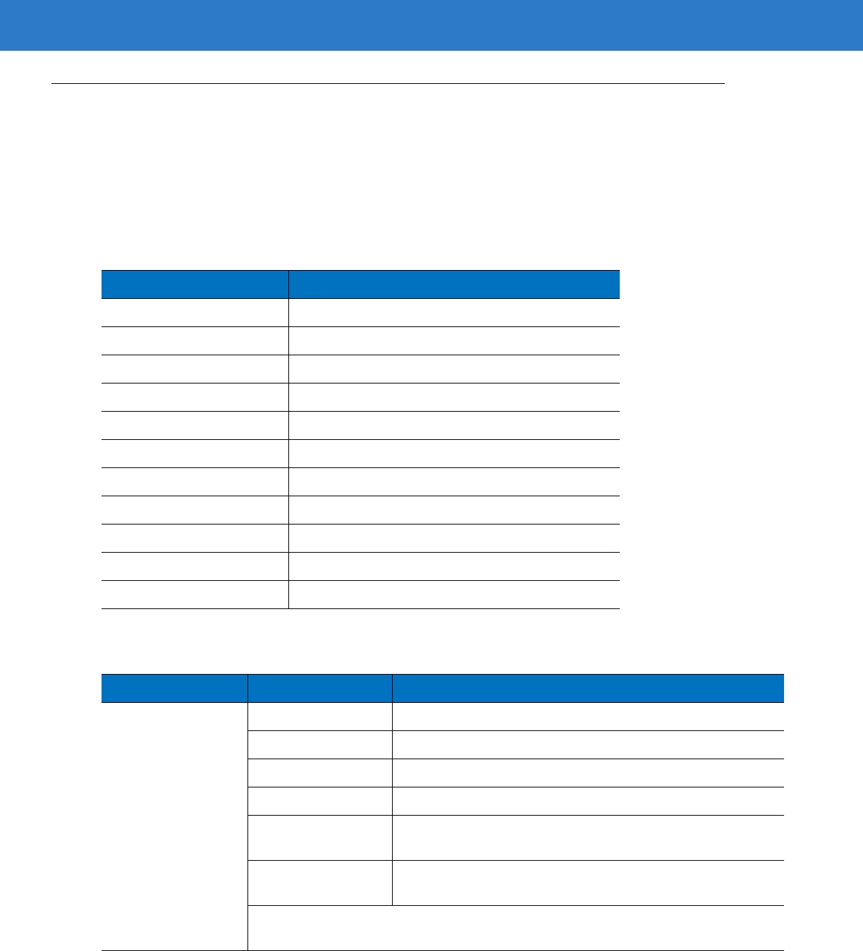
B - 2 Symbol LS4208 Product Reference Guide
AIM Code Identifiers
Each AIM Code Identifier contains the three-character string ]cm where:
] = Flag Character (ASCII 93)
c = Code Character (see Table B-2)
m = Modifier Character (see Table B-3)
The modifier character is the sum of the applicable option values based on Table B-3.
Table B-2
Aim Code Characters
Code Character Code Type
A Code 39, Code 39 Full ASCII, Code 32
C Code 128 (all variants), Coupon (Code 128 portion)
E UPC/EAN, Coupon (UPC portion)
eGS1 DataBar Family
F Codabar
G Code 93
H Code 11
I Interleaved 2 of 5
MMSI
S D2 of 5, IATA 2 of 5
X Bookland EAN, Code 39 Trioptic
Table B-3
Modifier Characters
Code Type Option Value Option
Code 39 0 No check character or Full ASCII processing.
1 Reader has checked one check character.
3 Reader has checked and stripped check character.
4 Reader has performed Full ASCII character conversion.
5 Reader has performed Full ASCII character conversion and
checked one check character.
7 Reader has performed Full ASCII character conversion and
checked and stripped check character.
Example: A Full ASCII bar code with check character W,
A+I+MI+DW
, is transmitted as
]A7
AIMID where 7 = (3+4).
Programming References B - 3
Trioptic Code 39 0 No option specified at this time. Always transmit 0.
Example: A Trioptic bar code 412356 is transmitted as
]X0
412356
Code 128 0 Standard data packet, no Function code 1 in first symbol
position.
1 Function code 1 in first symbol character position.
2 Function code 1 in second symbol character position.
Example: A Code (EAN) 128 bar code with Function 1 character
FNC1
in the first
position, AIMID is transmitted as
]
C1
AIMID
I 2 of 5 0 No check digit processing.
1 Reader has validated check digit.
3 Reader has validated and stripped check digit.
Example: An I 2 of 5 bar code without check digit, 4123, is transmitted as
]I0
4123
Codabar 0 No check digit processing.
1 Reader has checked check digit.
3 Reader has stripped check digit before transmission.
Example: A Codabar bar code without check digit, 4123, is transmitted as
]F0
4123
Code 93 0 No options specified at this time. Always transmit 0.
Example: A Code 93 bar code 012345678905 is transmitted as
]G0
012345678905
MSI 0 Check digits are sent.
1 No check digit is sent.
Example: An MSI bar code 4123, with a single check digit checked, is transmitted as
]M1
4123
D 2 of 5 0 No options specified at this time. Always transmit 0.
Example: A D 2 of 5 bar code 4123, is transmitted as
]S0
4123
UPC/EAN 0 Standard packet in full EAN country code format, which is 13
digits for UPC-A and UPC-E (not including supplemental data).
1 Two-digit supplement data only.
2 Five-digit supplement data only.
4 EAN-8 data packet.
Example: A UPC-A bar code 012345678905 is transmitted as
]E0
0012345678905
Table B-3
Modifier Characters (Continued)
Code Type Option Value Option

B - 4 Symbol LS4208 Product Reference Guide
Bookland EAN 0 No options specified at this time. Always transmit 0.
Example: A Bookland EAN bar code 123456789X is transmitted as
]X0
123456789X
Code 11 0 Single check digit
1 Two check digits
3 Check characters validated but not transmitted.
GS1 DataBar Family No option specified at this time. Always transmit 0.
GS1 DataBar-14 and GS1 DataBar Limited transmit with an
Application Identifier “01”.Note: In GS1-128 emulation mode,
GS1 DataBar is transmitted using Code 128 rules (i.e., ]C1).
Example: A DataBar-14 bar code 0110012345678902 is transmitted as
]e00110012345678902
.
Table B-3
Modifier Characters (Continued)
Code Type Option Value Option

Appendix C Sample Bar Codes
Code 39
UPC/EAN
UPC-A, 100%
123ABC
0
12
3
4
5
6
7
8
9
0
5
C - 2 Symbol LS4208 Product Reference Guide
EAN-13, 100%
Code 128
Interleaved 2 of 5
3
4
5
6
7
8
9
0
12
3
4
0
12345678901234567890123456789012345678901234
12345678901231
Sample Bar Codes C - 3
GS1 DataBar
GS1 DataBar
NOTE GS1 DataBar variants must be enabled to read the bar codes below (see GS1 DataBar
(formerly RSS - Reduced Space Symbology) on page 12-53).
10293847560192837465019283746029478450366523
(GS1 DataBar Expanded Stacked)
1234890hjio9900mnb
(GS1 DataBar Expanded)
08672345650916
(GS1 DataBar Limited)

C - 4 Symbol LS4208 Product Reference Guide
GS1 DataBar-14
55432198673467
(GS1 DataBar-14 Truncated)
90876523412674
(GS1 DataBar-14 Stacked)
78123465709811
(GS1 DataBar-14 Stacked Omni-Directional)

Appendix D Numeric Bar Codes
Numeric Bar Codes
For parameters requiring specific numeric values, scan the appropriately numbered bar code(s).
0
1
2
3
D - 2 Symbol LS4208 Product Reference Guide
Numeric Bar Codes (continued)
For parameters requiring specific numeric values, scan the appropriately numbered bar code(s).
4
5
6
7
8
9

Numeric Bar Codes D - 3
Cancel
To correct an error or change a selection, scan the bar code below.
Cancel

D - 4 Symbol LS4208 Product Reference Guide
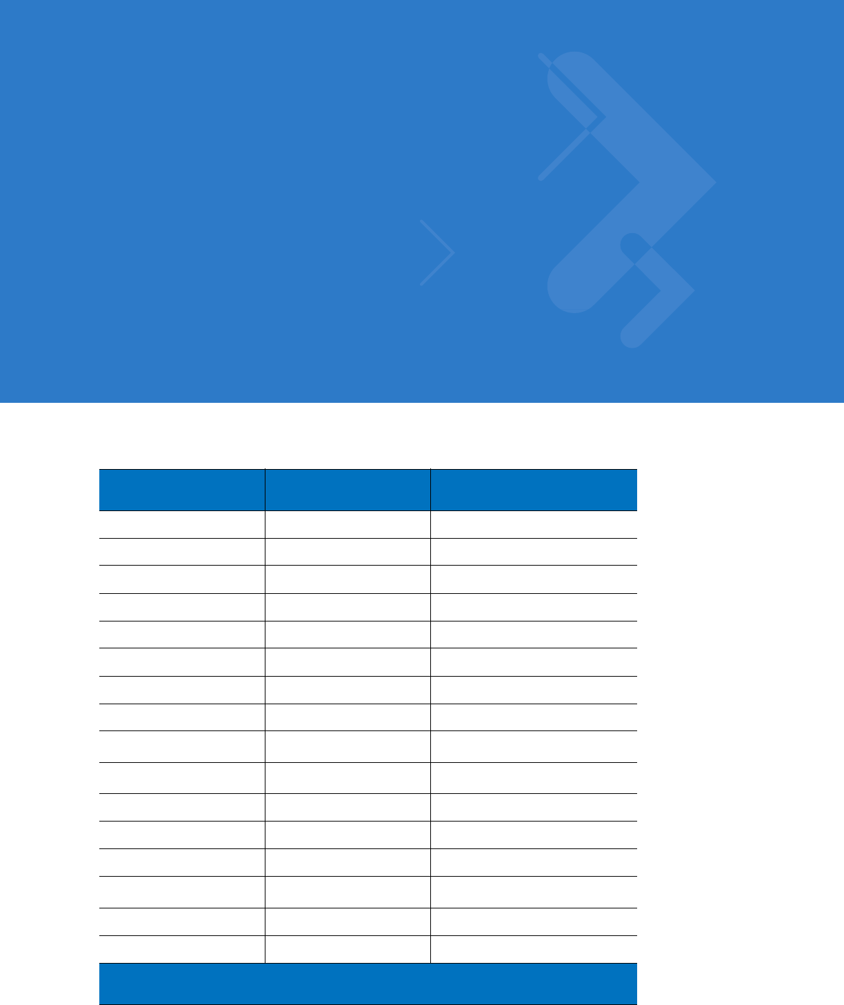
Appendix E ASCII Character Sets
Table E-1
ASCII Value Standard Default Parameters Table
ASCII Value Full ASCII Code 39
Encode Character Keystroke
1000 %U CTRL 2
1001 $A CTRL A
1002 $B CTRL B
1003 $C CTRL C
1004 $D CTRL D
1005 $E CTRL E
1006 $F CTRL F
1007 $G CTRL G
1008 $H CTRL H/
BACKSPACE
1
1009 $I CTRL I/
HORIZONTAL TAB
1
1010 $J CTRL J
1011 $K CTRL K
1012 $L CTRL L
1013 $M CTRL M/
ENTER
1
1014 $N CTRL N
1015 $O CTRL O
The keystroke in bold is sent only if the “Function Key Mapping” is enabled.
Otherwise, the unbolded keystroke is sent.

E - 2 Symbol LS4208 Product Reference Guide
1016 $P CTRL P
1017 $Q CTRL Q
1018 $R CTRL R
1019 $S CTRL S
1020 $T CTRL T
1021 $U CTRL U
1022 $V CTRL V
1023 $W CTRL W
1024 $X CTRL X
1025 $Y CTRL Y
1026 $Z CTRL Z
1027 %A CTRL [
1028 %B CTRL \
1029 %C CTRL ]
1030 %D CTRL 6
1031 %E CTRL -
1032 Space Space
1033 /A !
1034 /B “
1035 /C #
1036 /D ?
1037 /E %
1038 /F &
1039 /G ‘
1040 /H (
1041 /I )
1042 /J *
1043 /K +
Table E-1
ASCII Value Standard Default Parameters Table (Continued)
ASCII Value Full ASCII Code 39
Encode Character Keystroke
The keystroke in bold is sent only if the “Function Key Mapping” is enabled.
Otherwise, the unbolded keystroke is sent.

ASCII Character Sets E - 3
1044 /L ,
1045 - -
1046 . .
1047 /o /
1048 0 0
1049 1 1
1050 2 2
1051 3 3
1052 4 4
1053 5 5
1054 6 6
1055 7 7
1056 8 8
1057 9 9
1058 /Z :
1059 %F ;
1060 %G <
1061 %H =
1062 %I >
1063 %J ?
1064 %V @
1065 A A
1066 B B
1067 C C
1068 D D
1069 E E
1070 F F
1071 G G
Table E-1
ASCII Value Standard Default Parameters Table (Continued)
ASCII Value Full ASCII Code 39
Encode Character Keystroke
The keystroke in bold is sent only if the “Function Key Mapping” is enabled.
Otherwise, the unbolded keystroke is sent.

E - 4 Symbol LS4208 Product Reference Guide
1072 H H
1073 I I
1074 J J
1075 K K
1076 L L
1077 M M
1078 N N
1079 O O
1080 P P
1081 Q Q
1082 R R
1083 S S
1084 T T
1085 U U
1086 V V
1087 W W
1088 X X
1089 Y Y
1090 Z Z
1091 %K [
1092 %L \
1093 %M ]
1094 %N ^
1095 %O _
1096 %W ‘
1097 +A a
1098 +B b
1099 +C c
Table E-1
ASCII Value Standard Default Parameters Table (Continued)
ASCII Value Full ASCII Code 39
Encode Character Keystroke
The keystroke in bold is sent only if the “Function Key Mapping” is enabled.
Otherwise, the unbolded keystroke is sent.

ASCII Character Sets E - 5
1100 +D d
1101 +E e
1102 +F f
1103 +G g
1104 +H h
1105 +I i
1106 +J j
1107 +K k
1108 +L l
1109 +M m
1110 +N n
1111 +O o
1112 +P p
1113 +Q q
1114 +R r
1115 +S s
1116 +T t
1117 +U u
1118 +V v
1119 +W w
1120 +X x
1121 +Y y
1122 +Z z
1123 %P {
1124 %Q I
1125 %R }
1126 %S ~
Table E-1
ASCII Value Standard Default Parameters Table (Continued)
ASCII Value Full ASCII Code 39
Encode Character Keystroke
The keystroke in bold is sent only if the “Function Key Mapping” is enabled.
Otherwise, the unbolded keystroke is sent.

E - 6 Symbol LS4208 Product Reference Guide
Table E-2
ALT Key Standard Default Tables
ALT Keys Keystroke
2064 ALT 2
2065 ALT A
2066 ALT B
2067 ALT C
2068 ALT D
2069 ALT E
2070 ALT F
2071 ALT G
2072 ALT H
2073 ALT I
2074 ALT J
2075 ALT K
2076 ALT L
2077 ALT M
2078 ALT N
2079 ALT O
2080 ALT P
2081 ALT Q
2082 ALT R
2083 ALT S
2084 ALT T
2085 ALT U
2086 ALT V
2087 ALT W
2088 ALT X
2089 ALT Y
2090 ALT Z
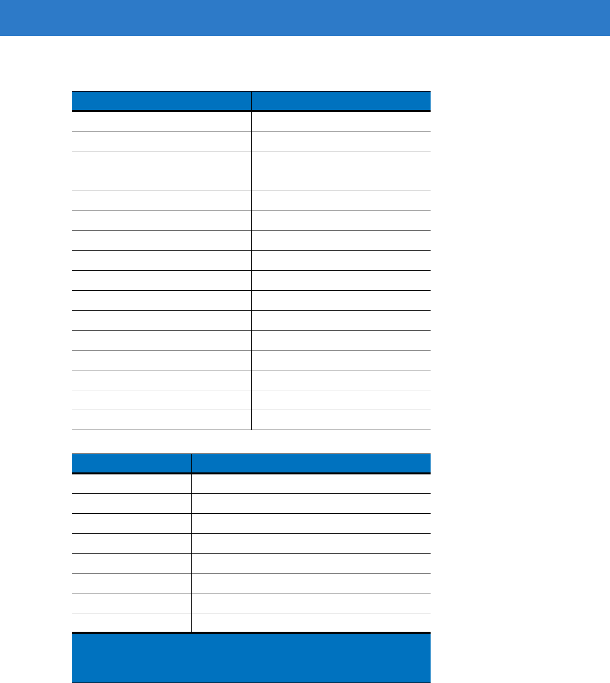
ASCII Character Sets E - 7
Table E-3
Misc. Key Standard Default Table
Misc. Key Keystroke
3001 PA 1
3002 PA 2
3003 CMD 1
3004 CMD 2
3005 CMD 3
3006 CMD 4
3007 CMD 5
3008 CMD 6
3009 CMD 7
3010 CMD 8
3011 CMD 9
3012 CMD 10
3013 CMD 11
3014 CMD 12
3015 CMD 13
3016 CMD 14
Table E-4
GUI Shift Keys
Other Value Keystroke
3048 GUI 0
3049 GUI 1
3050 GUI 2
3051 GUI 3
3052 GUI 4
3053 GUI 5
3054 GUI 6
3055 GUI 7
GUI Shift Keys
The Apple™ iMac keyboard has an apple key on either side of the space
bar. Windows-based systems have a GUI key to the left of the left ALT
key, and to the right of the right ALT key.

E - 8 Symbol LS4208 Product Reference Guide
3056 GUI 8
3057 GUI 9
3065 GUI A
3066 GUI B
3067 GUI C
3068 GUI D
3069 GUI E
3070 GUI F
3071 GUI G
3072 GUI H
3073 GUI I
3074 GUI J
3075 GUI K
3076 GUI L
3077 GUI M
3078 GUI N
3079 GUI O
3080 GUI P
3081 GUI Q
3082 GUI R
3083 GUI S
3084 GUI T
3085 GUI U
3086 GUI V
3087 GUI W
Table E-4
GUI Shift Keys (Continued)
Other Value Keystroke
GUI Shift Keys
The Apple™ iMac keyboard has an apple key on either side of the space
bar. Windows-based systems have a GUI key to the left of the left ALT
key, and to the right of the right ALT key.
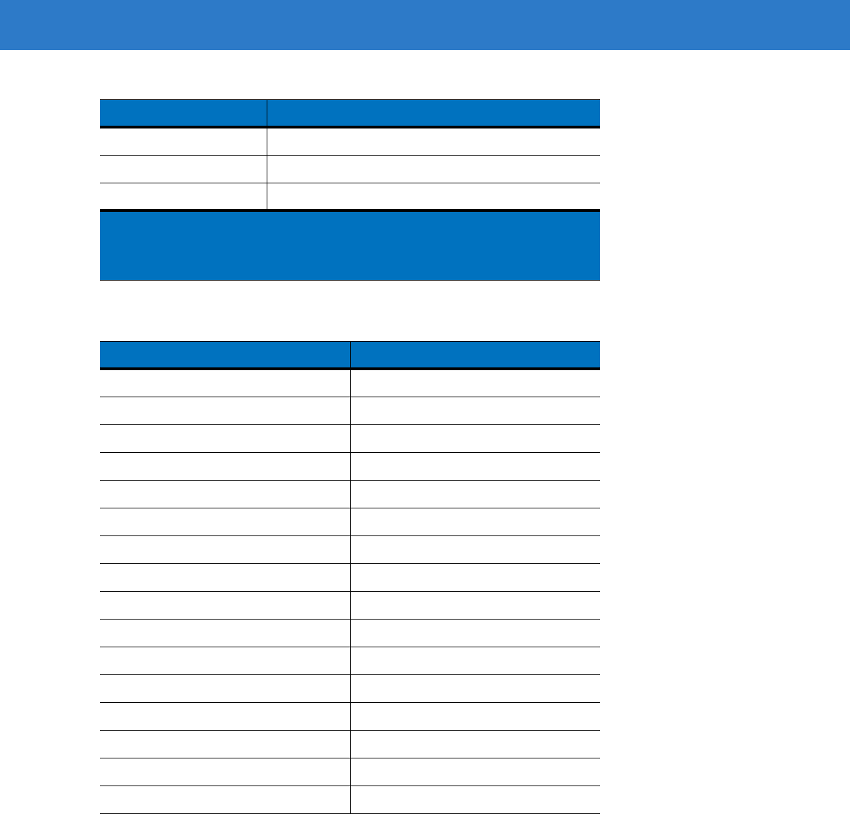
ASCII Character Sets E - 9
3088 GUI X
3089 GUI Y
3090 GUI Z
Table E-5
PF Key Standard Default Table
PF Keys Keystroke
4001 PF 1
4002 PF 2
4003 PF 3
4004 PF 4
4005 PF 5
4006 PF 6
4007 PF 7
4008 PF 8
4009 PF 9
4010 PF 10
4011 PF 11
4012 PF 12
4013 PF 13
4014 PF 14
4015 PF 15
4016 PF 16
Table E-4
GUI Shift Keys (Continued)
Other Value Keystroke
GUI Shift Keys
The Apple™ iMac keyboard has an apple key on either side of the space
bar. Windows-based systems have a GUI key to the left of the left ALT
key, and to the right of the right ALT key.

E - 10 Symbol LS4208 Product Reference Guide
Table E-6
F key Standard Default Table
F Keys Keystroke
5001 F 1
5002 F 2
5003 F 3
5004 F 4
5005 F 5
5006 F 6
5007 F 7
5008 F 8
5009 F 9
5010 F 10
5011 F 11
5012 F 12
5013 F 13
5014 F 14
5015 F 15
5016 F 16
5017 F 17
5018 F 18
5019 F 19
5020 F 20
5021 F 21
5022 F 22
5023 F 23
5024 F 24

ASCII Character Sets E - 11
Table E-7
Numeric Key Standard Default Table
Numeric Keypad Keystroke
6042 *
6043 +
6044 Undefined
6045 -
6046 .
6047 /
6048 0
6049 1
6050 2
6051 3
6052 4
6053 5
6054 6
6055 7
6056 8
6057 9
6058 Enter
6059 Num Lock

E - 12 Symbol LS4208 Product Reference Guide
Table E-8
Extended Keypad Standard Default Table
Extended Keypad Keystroke
7001 Break
7002 Delete
7003 Pg Up
7004 End
7005 Pg Dn
7006 Pause
7007 Scroll Lock
7008 Backspace
7009 Tab
7010 Print Screen
7011 Insert
7012 Home
7013 Enter
7014 Escape
7015 Up Arrow
7016 Dn Arrow
7017 Left Arrow
7018 Right Arrow

Index
Numerics
123Scan configuration . . . . . . . . . . . . . . . . . . . . . . . 11-1
A
actions . . . . . . . . . . . . . . . . . . . . . . . . . . . . . . . . . . . 14-2
ADF . . . . . . . . . . . . . . . . . . . . . . . . . . . . . . . . . . . . . 14-1
actions . . . . . . . . . . . . . . . . . . . . . . . . . . .14-1, 14-23
move cursor . . . . . . . . . . . . . . . . . .14-27, 14-28
send data . . . . . . . . . . . . . . . . . . . . . . . . . 14-23
setup fields . . . . . . . . . . . . . . . . . . . . . . . . 14-26
alphanumeric keyboard . . . . . . . . . . . . . . . . . . 14-83
alternate rule sets . . . . . . . . . . . . . . . . . . . . . . . 14-3
bar code list . . . . . . . . . . . . . . . . . . . . . . . . . . . . 14-5
bar code menu example . . . . . . . . . . . . . . . . . . 14-2
beep . . . . . . . . . . . . . . . . . . . . . . . . . . . . . . . . 14-42
code lengths . . . . . . . . . . . . . . . . . . . . . . . . . . 14-15
code types . . . . . . . . . . . . . . . . . . . . . . . . . . . . 14-11
criteria . . . . . . . . . . . . . . . . . . . . . . . . . . .14-1, 14-11
default rules . . . . . . . . . . . . . . . . . . . . . . . . . . . 14-5
invalid rule . . . . . . . . . . . . . . . . . . . . . . . . . . . . . . 3-2
move cursor past a character . . . . . . . . . . . . . 14-26
move cursor past string . . . . . . . . . . . . . . . . . . 14-26
move cursor to a character . . . . . . . . . . . . . . . 14-26
move cursor to last occurrence of string and
replace . . . . . . . . . . . . . . . . . . . . . . . . 14-26
move cursor to start of data . . . . . . . . . . . . . . 14-26
move cursor to string and replace . . . . . . . . . . 14-26
numeric keypad . . . . . . . . . . . . . . . . . . . . . . . . 14-21
pad spaces . . . . . . . . . . . . . . . . . . . . . . . . . . . 14-34
pad zeros . . . . . . . . . . . . . . . . . . . . . . . . . . . . 14-38
rules . . . . . . . . . . . . . . . . . . . . . . . . . 9-7, 11-1, 14-1
rules hierarchy . . . . . . . . . . . . . . . . . . . . . . . . . 14-4
send alt characters . . . . . . . . . . . . . . . . . . . . . 14-59
send control characters . . . . . . . . . . . . . . . . . . 14-43
send function key . . . . . . . . . . . . . . . . . . . . . . 14-68
send keyboard characters . . . . . . . . . . . . . . . 14-47
send keypad characters . . . . . . . . . . . . . . . . . 14-63
send preset value . . . . . . . . . . . . . . . . . . . . . . 14-27
send value . . . . . . . . . . . . . . . . . . . . . . . . . . . 14-32
skip ahead "n" characters . . . . . . . . . . . . . . . . 14-27
skip ahead characters . . . . . . . . . . . . . . . . . . 14-29
skip back "n" characters . . . . . . . . . . . . . . . . . 14-27
skip back characters . . . . . . . . . . . . . . . . . . . . 14-31
skip cursor to end . . . . . . . . . . . . . . . . . . . . . . 14-26
space removal . . . . . . . . . . . . . . . . . . . . . . . . 14-33
special commands . . . . . . . . . . . . . . . . . . . . . . 14-8
specific data string . . . . . . . . . . . . . . . . . . . . . 14-19
specific string
any location . . . . . . . . . . . . . . . . . . . . . . . 14-19
any message ok . . . . . . . . . . . . . . . . . . . . 14-20
at start . . . . . . . . . . . . . . . . . . . . . . . . . . . 14-19
rule belongs to set . . . . . . . . . . . . . . . . . . 14-22
search . . . . . . . . . . . . . . . . . . . . . . . . . . . 14-20
transmit error . . . . . . . . . . . . . . . . . . . . . . . . 2-2, 3-2
turn off rule sets . . . . . . . . . . . . . . . . . . . . . . . 14-82
zero removal . . . . . . . . . . . . . . . . . . . . . . . . . . 14-33
advanced data formatting . . . . . 2-2, 3-2, 9-7, 11-1, 14-1
actions . . . . . . . . . . . . . . . . . . . . . . . . . . 14-1, 14-23
alphanumeric keyboard . . . . . . . . . . . . . . . . . 14-83
alternate rule sets . . . . . . . . . . . . . . . . . . . . . . . 14-3
bar code menu example . . . . . . . . . . . . . . . . . . 14-2
beep . . . . . . . . . . . . . . . . . . . . . . . . . . . . . . . . 14-42
code lengths . . . . . . . . . . . . . . . . . . . . . . . . . . 14-15
code types . . . . . . . . . . . . . . . . . . . . . . . . . . . 14-11
criteria . . . . . . . . . . . . . . . . . . . . . . . . . . . 14-1, 14-11
default rules . . . . . . . . . . . . . . . . . . . . . . . . . . . 14-5
numeric keypad . . . . . . . . . . . . . . . . . . . . . . . 14-21
pad spaces . . . . . . . . . . . . . . . . . . . . . . . . . . . 14-34
pad zeros . . . . . . . . . . . . . . . . . . . . . . . . . . . . 14-38
rules . . . . . . . . . . . . . . . . . . . . . . . . . . . . . . . . . 14-1
rules hierarchy . . . . . . . . . . . . . . . . . . . . . . . . . 14-4
send alt characters . . . . . . . . . . . . . . . . . . . . . 14-59

Index - 2 Symbol LS4208 Product Reference Guide
send control characters . . . . . . . . . . . . . . . . . . 14-43
send function key . . . . . . . . . . . . . . . . . . . . . . 14-68
send keyboard characters . . . . . . . . . . . . . . . . 14-47
send keypad characters . . . . . . . . . . . . . . . . . 14-63
send preset value . . . . . . . . . . . . . . . . . . . . . . 14-32
setup fields . . . . . . . . . . . . . . . . . . . . . . . . . . . 14-26
skip ahead characters . . . . . . . . . . . . . . . . . . . 14-29
skip back characters . . . . . . . . . . . . . . . . . . . . 14-31
space removal . . . . . . . . . . . . . . . . . . . . . . . . . 14-33
special commands . . . . . . . . . . . . . . . . . . . . . . 14-8
specific data string . . . . . . . . . . . . . . . . . . . . . 14-19
turn off rule sets . . . . . . . . . . . . . . . . . . . . . . . 14-82
zero removal . . . . . . . . . . . . . . . . . . . . . . . . . . 14-33
aiming . . . . . . . . . . . . . . . . . . . . . . . . . . . . . . . . . . . . 2-6
ASCII values
keyboard wedge . . . . . . . . . . . . . . . . . . . . . . . . 5-13
RS-232 . . . . . . . . . . . . . . . . . . . . . . . . . . . . . . . 6-18
standard defaults . . . . . . . . . . . . . . . . . . . . . . . . E-1
USB . . . . . . . . . . . . . . . . . . . . . . . . . . . . . . . . . . 7-12
assembling the stand . . . . . . . . . . . . . . . . . . . . . . . . . 2-9
B
bar code defaults
all . . . . . . . . . . . . . . . . . . . . . . . . . . . . . . . . . . . . A-1
IBM . . . . . . . . . . . . . . . . . . . . . . . . . . . . . . . . . . . 8-3
keyboard wedge . . . . . . . . . . . . . . . . . . . . . . . . . 5-3
miscellaneous . . . . . . . . . . . . . . . . . . . . . . . . . . 13-2
RS-232 . . . . . . . . . . . . . . . . . . . . . . . . . . . . . . . . 6-3
scanner emulation . . . . . . . . . . . . . . . . . . . . . . . 10-3
symbologies . . . . . . . . . . . . . . . . . . . . . . . . . . . 12-2
USB . . . . . . . . . . . . . . . . . . . . . . . . . . . . . . . . . . . 7-4
user preferences . . . . . . . . . . . . . . . . . . . . . . . . . 4-2
wand emulation . . . . . . . . . . . . . . . . . . . . . . . . . . 9-3
bar codes
123Scan . . . . . . . . . . . . . . . . . . . . . . . . . . . . . . 11-1
ADF list . . . . . . . . . . . . . . . . . . . . . . . . . . . . . . . 14-5
beep after good decode . . . . . . . . . . . . . . . . . . . 4-9
beeper tone . . . . . . . . . . . . . . . . . . . . . . . . . . . . . 4-4
beeper volume . . . . . . . . . . . . . . . . . . . . . . . . . . 4-5
cancel . . . . . . . . . . . . . . . . . . . . . . . . . . . . . . . . . D-3
data options
pause duration . . . . . . . . . . . . . . . . . . . . . . 14-8
IBM 468X/469X
convert unkown to code 39 . . . . . . . . . . . . . . 8-5
ignore bar code configuration . . . . . . . . . . . . 8-6
ignore beep . . . . . . . . . . . . . . . . . . . . . . . . . . 8-6
port address . . . . . . . . . . . . . . . . . . . . . . . . . 8-4
keyboard wedge
alternate numeric keypad emulation . . . . . . . 5-8
caps lock on . . . . . . . . . . . . . . . . . . . . . . . . . 5-8
capsl ock override . . . . . . . . . . . . . . . . . . . . . 5-9
country keyboard types (country codes) . . . . 5-5
host types . . . . . . . . . . . . . . . . . . . . . . . . . . . 5-4
ignore unknown characters . . . . . . . . . . . . . . 5-6
intra-keystroke delay . . . . . . . . . . . . . . . . . . . 5-7
keystroke delay . . . . . . . . . . . . . . . . . . . . . . . 5-7
laser on time . . . . . . . . . . . . . . . . . . . . . . . . . . . . 4-9
miscellaneous
FN1 sub values . . . . . . . . . . . . . . . . . . . . . . 13-6
prefix/suffix values . . . . . . . . . . . . . . . . . . . 13-3
scan data transmission format . . . . . . . . . . 13-4
synapse interface . . . . . . . . . . . . . . . . . . . . 13-7
transmit code ID . . . . . . . . . . . . . . . . . . . . . 13-3
transmit no read msg . . . . . . . . . . . . . . . . . 13-6
numeric bar codes . . . . . . . . . . . . . . . . . . . . . . . .D-3
parameter scanning . . . . . . . . . . . . . . . . . . . . . . . 4-4
power mode . . . . . . . . . . . . . . . . . . . . . . . . . . . . . 4-5
raster height . . . . . . . . . . . . . . . . . . . . . . . . . . . . 4-8
report synapse cable . . . . . . . . . . . . . . . . . . . . . 13-8
report version . . . . . . . . . . . . . . . . . . . . . . . . . . 13-8
RS-232
baud rate . . . . . . . . . . . . . . . . . . . . . . . . . . . . 6-7
beep on . . . . . . . . . . . . . . . . . . . . . . . . . . . . 6-15
check receive errors . . . . . . . . . . . . . . . . . . 6-10
data bits . . . . . . . . . . . . . . . . . . . . . . . . . . . . 6-9
hardware handshaking . . . . . . . . . . . . . . . . 6-10
host serial response time-out . . . . . . . . . . . 6-14
host types . . . . . . . . . . . . . . . . . . . . . . . . . . . 6-6
ignore unkown characters . . . . . . . . . . . . . . 6-17
intercharacter delay . . . . . . . . . . . . . . . . . . 6-16
Nixdorf Beep/LED options . . . . . . . . . . . . . . 6-17
parity . . . . . . . . . . . . . . . . . . . . . . . . . . . . . . . 6-8
RTS line state . . . . . . . . . . . . . . . . . . . . . . . 6-15
software handshaking . . . . . . . . . . . . 6-12, 6-13
stop bit select . . . . . . . . . . . . . . . . . . . . . . . . 6-9
scan line width . . . . . . . . . . . . . . . . . . . . . . . . . . . 4-7
scan patterns . . . . . . . . . . . . . . . . . . . . . . . . . . . . 4-6
set defaults . . . . . . . . . . . . . . . . . . . . . . . . . . . . . 4-3
symbologies
bi-directional redundancy . . . . . . . . . . . . . 12-66
bookland EAN, enable/disable . . . . . . . . . . 12-9
Chinese 2 of 5, enable/disable . . . . . . . . . 12-46
codabar CLSI editing . . . . . . . . . . . . . . . . 12-49
codabar lengths . . . . . . . . . . . . . . . . . . . . 12-47
codabar NOTIS editing . . . . . . . . . . . . . . . 12-49
codabar, enable/disable . . . . . . . . . . . . . . 12-47
code 11 check digit verification . . . . . . . . . 12-38
code 11 lengths . . . . . . . . . . . . . . . . . . . . . 12-36
code 11, transmit check digits . . . . . . . . . . 12-39
code 128, enable/disable . . . . . . . . . . . . . 12-23
code 39 buffering . . . . . . . . . . . . . . . . . . . 12-31
code 39 check digit verification . . . . . . . . . 12-28
code 39 full ASCII conversion . . . . . . . . . . 12-30
code 39 lengths . . . . . . . . . . . . . . . 12-27, 12-28
code 39 transmit buffer . . . . . . . . . . . . . . . 12-32
code 39 transmit check digit . . . . . . . . . . . 12-29
code 39, enable/disable . . . . . . . . . . . . . . 12-25

Index - 3
code 93 lengths . . . . . . . . . . . . . . . . . . . . 12-34
code 93, enable/disable . . . . . . . . . . . . . . 12-34
convert UPC-E to UPC-A . . . . . . . . . . . . . 12-19
convert UPC-E1 to UPC-A . . . . . . . . . . . . 12-19
discrete 2 of 5 lengths . . . . . . . . . . . . . . . 12-44
discrete 2 of 5, enable/disable . . . . . . . . . 12-44
EAN-13/EAN-8, enable/disable . . . . . . . . . 12-8
EAN-8/JAN-8 extend . . . . . . . . . . . . . . . . 12-20
GS1 DataBar, convert to UPC/EAN . . . . . 12-54
GS1 DataBar, enable/disable . . . . . . . . . . 12-53
GS1-128, enable/disable . . . . . . . . . . . . . 12-23
I 2 of 5 check digit verification . . . . . . . . . 12-42
I 2 of 5 convert to EAN-13 . . . . . . . . . . . . 12-43
I 2 of 5 lengths . . . . . . . . . . . . . . . . . . . . . 12-40
I 2 of 5 transmit check digit . . . . . . . . . . . . 12-43
I 2 of 5, enable/disable . . . . . . . . . . . . . . . 12-40
intercharacter gap . . . . . . . . . . . . . . . . . . . 12-66
ISBT 128, enable/disable . . . . . . . . . . . . . 12-24
MSI check digit algorithm . . . . . . . . . . . . . 12-52
MSI check digits . . . . . . . . . . . . . . . . . . . . 12-51
MSI lengths . . . . . . . . . . . . . . . . . . . . . . . . 12-50
MSI transmit check digits . . . . . . . . . . . . . 12-52
MSI, enable/disable . . . . . . . . . . . . . . . . . 12-50
redundancy levels . . . . . . . . . . . . . . . . . . . 12-63
security levels . . . . . . . . . . . . . . . . . . . . . . 12-65
bi-directional redundancy . . . . . . . . . . 12-66
supplementals . . . . . . . . . . . . . . . . . . . . . . 12-9
trioptic code 39, enable/disable . . . . . . . . 12-25
UCC coupon extended code . . . . . . . . . . 12-22
UPC/EAN/JAN supplemental redundancy 12-14
UPC-A preamble . . . . . . . . . . . . . . . . . . . 12-16
UPC-A transmit check digit . . . . . . . . . . . . 12-14
UPC-A/UPC-E, enable/disable . . . . . . . . . . 12-6
UPC-E preamble . . . . . . . . . . . . . . . . . . . 12-17
UPC-E transmit check digit . . . . . . . . . . . . 12-15
UPC-E1 preamble . . . . . . . . . . . . . . . . . . 12-18
UPC-E1 transmit check digit . . . . . . . . . . . 12-15
UPC-E1, enable/disable . . . . . . . . . . . . . . . 12-7
USB
caps lock override . . . . . . . . . . . . . . . . . . . . . 7-8
country keyboard types . . . . . . . . . . . . . . . . 7-6
device type . . . . . . . . . . . . . . . . . . . . . . . . . . 7-5
keystroke delay . . . . . . . . . . . . . . . . . . . . . . . 7-8
unknown characters . . . . . . . . . . . . . . . . . . . 7-9
wand emulation
code 39 full ASCII . . . . . . . . . . . . . . . . . . . . . 9-8
convert all bar codes to code 39 . . . . . . . . . . 9-7
host types . . . . . . . . . . . . . . . . . . . . . . . . . . . 9-4
leading margin (quiet zone) . . . . . . . . . . . . . 9-5
polarity . . . . . . . . . . . . . . . . . . . . . . . . . . . . . 9-6
unknown characters . . . . . . . . . . . . . . . . . . . 9-6
beeper definitions . . . . . . . . . . . . . . . . . . . . . . . . . . . 2-2
bullets . . . . . . . . . . . . . . . . . . . . . . . . . . . . . . . . . . . . .xiv
C
cables
installing . . . . . . . . . . . . . . . . . . . . . . . . . . . . . . . 1-3
interface . . . . . . . . . . . . . . . . . . . . . . . . . . . . . . . . 1-4
removing cables . . . . . . . . . . . . . . . . . . . . . . . . . 1-4
character set . . . . . . . . . . . . . . . . . 5-13, 6-18, 7-12, E-1
Chinese 2 of 5 bar codes . . . . . . . . . . . . . . . . . . . . 12-46
codabar bar codes . . . . . . . . . . . . . . . . . . . . . . . . . 12-47
code 11 bar codes . . . . . . . . . . . . . . . . . . . . . . . . . 12-36
code 128 bar codes . . . . . . . . . . . . . . . . . . . . . . . . 12-23
code 39 bar codes . . . . . . . . . . . . . . . . . . . . . . . . . 12-25
code 93 bar codes . . . . . . . . . . . . . . . . . . . . . . . . . 12-34
code identifiers
AIM code IDs . . . . . . . . . . . . . . . . . . . . . . . . . . . . B-2
Symbol code IDs . . . . . . . . . . . . . . . . . . . . . . . . . B-1
codewords . . . . . . . . . . . . . . . . . . . . . . . . . . . . . . . 12-57
transmit unknown . . . . . . . . . . . . . . . . . . . . . . 12-58
conventions
notational . . . . . . . . . . . . . . . . . . . . . . . . . . . . . . . xiv
converting SSI param numbers to SNAPI . . . . . 2-5, 2-6,
. . . . .2-8, 2-10, 3-4, 4-2, 5-2, 5-3, 6-2, 6-3, 7-3, 7-4, 7-6,
. . . . . . . . .8-2, 8-3, 8-4, 9-3, 9-7, 10-2, 10-3, 12-2, 12-9,
. . . . . . . . . . . . . . . .12-21, 12-22, 12-30, 13-2, 13-3, C-3
D
decode zone . . . . . . . . . . . . . . . . . . . . . . . . . . . . . . 2-11
default parameters
all . . . . . . . . . . . . . . . . . . . . . . . . . . . . . . . . . . . . . A-1
IBM . . . . . . . . . . . . . . . . . . . . . . . . . . . . . . . . . . . 8-3
keyboard wedge . . . . . . . . . . . . . . . . . . . . . . . . . 5-3
miscellaneous . . . . . . . . . . . . . . . . . . . . . . . . . . 13-2
RS-232 . . . . . . . . . . . . . . . . . . . . . . . . . . . . . . . . 6-3
scanner emulation . . . . . . . . . . . . . . . . . . . . . . . 10-3
standard default table . . . . . . . . . . . . . . . . . . . . . E-1
symbologies . . . . . . . . . . . . . . . . . . . . . . . . . . . 12-2
USB . . . . . . . . . . . . . . . . . . . . . . . . . . . . . . . . . . . 7-4
user preferences . . . . . . . . . . . . . . . . . . . . . . . . . 4-2
wand emulation . . . . . . . . . . . . . . . . . . . . . . . . . . 9-3
discrete 2 of 5 bar codes . . . . . . . . . . . . . . . . . . . . 12-44
DTF bar codes . . . . . . . . . . . . . . . . . . . . . . . . . . . . 12-44
E
ECIdelete character set ECIs . . . . . . . . . . . . . . . . 12-59
error indications
ack/nak . . . . . . . . . . . . . . . . . . . . . . . . . . . . . . . 6-12
ADF . . . . . . . . . . . . . . . . . . . . . . . . . . . . . . . 2-2, 3-2
beeper . . . . . . . . . . . . . . . . . . . . . . . . . . . . . . . . . 4-9
enq . . . . . . . . . . . . . . . . . . . . . . . . . . . . . . . . . . 6-12
format . . . . . . . . . . . . . . . . . . . . . . . . . . . . . 2-2, 3-3
input . . . . . . . . . . . . . . . . . . . . . . . . . . . . . . . 2-2, 3-2

Index - 4 Symbol LS4208 Product Reference Guide
laser on time . . . . . . . . . . . . . . . . . . . . . . . . . . . . 4-9
miscellaneous scanner options . . . . . . . . . . . . . 13-1
RS-232 . . . . . . . . . . . . . . . . . . . . . . . . . . . . .2-2, 3-2
RS-232 transmission . . . . . . . . . . . . . . . . . . . . . 6-10
symbologies . . . . . . . . . . . . . . . . . . . . . . . . . . . 12-2
transmission . . . . . . . . . . . . . . . . 2-2, 2-3, 3-2, 6-14
unknown characters . . . . . . . . . . . . . . 5-6, 6-17, 7-9
user preferences . . . . . . . . . . . . . . . . . . . . . . . . . 4-1
xon/xoff . . . . . . . . . . . . . . . . . . . . . . . . . . . . . . . 6-12
escape characters . . . . . . . . . . . . . . . . . . . . . . . . . 12-58
G
GS1 DataBar bar codes . . . . . . . . . . . . . . . . . . . . 12-53
H
host types
IBM (port address) . . . . . . . . . . . . . . . . . . . . . . . 8-4
keyboard wedge . . . . . . . . . . . . . . . . . . . . . . . . . 5-4
RS-232 . . . . . . . . . . . . . . . . . . . . . . . . . . . . . . . . 6-6
scanner emulation . . . . . . . . . . . . . . . . . . . . . . . 10-4
USB . . . . . . . . . . . . . . . . . . . . . . . . . . . . . . . . . . . 7-5
wand emulation . . . . . . . . . . . . . . . . . . . . . . . . . . 9-4
I
IBM 468X/469X connection . . . . . . . . . . . . . . . . . . . . 8-2
IBM 468X/469X parameters . . . . . . . . . . . . . . . . . . . 8-4
IBM defaults . . . . . . . . . . . . . . . . . . . . . . . . . . . . . . . . 8-3
intellistand . . . . . . . . . . . . . . . . . . . . . . . . . . . . .2-9, 2-10
intercharacter gap . . . . . . . . . . . . . . . . . . . . . . . . . 12-66
interleaved 2 of 5 bar codes . . . . . . . . . . . . . . . . . 12-40
K
keyboard wedge connection . . . . . . . . . . . . . . . . . . . 5-2
keyboard wedge defaults . . . . . . . . . . . . . . . . . . . . . . 5-3
keyboard wedge parameters . . . . . . . . . . . . . . . . . . . 5-4
L
LED definitions . . . . . . . . . . . . . . . . . . . . . . . . . . . . . 2-3
M
macro PDF
delete character set ECIs . . . . . . . . . . . . . . . . 12-59
escape characters . . . . . . . . . . . . . . . . . . . . . . 12-58
transmit symbols in codeword format . . . . . . . 12-57
transmit unknown codewords . . . . . . . . . . . . . 12-58
maintenance . . . . . . . . . . . . . . . . . . . . . . . . . . . . . . . 3-1
miscellaneous defaults . . . . . . . . . . . . . . . . . . . . . . 13-2
Motorola enterprise mobility support . . . . . . . . . . . . . . xv
MSI bar codes . . . . . . . . . . . . . . . . . . . . . . . . . . . . 12-50
N
notational conventions . . . . . . . . . . . . . . . . . . . . . . . . xiv
NW - 7 . . . . . . . . . . . . . . . . . . . . . . . . . . . . . . . . . . 12-47
O
overview . . . . . . . . . . . . . . . . . . . . . . . . . . . . . . . . . . . 1-1
P
parameter defaults
all . . . . . . . . . . . . . . . . . . . . . . . . . . . . . . . . . . . . . A-1
IBM . . . . . . . . . . . . . . . . . . . . . . . . . . . . . . . . . . . 8-3
keyboard wedge . . . . . . . . . . . . . . . . . . . . . . . . . 5-3
miscellaneous . . . . . . . . . . . . . . . . . . . . . . . . . . 13-2
RS-232 . . . . . . . . . . . . . . . . . . . . . . . . . . . . . . . . 6-3
scanner emulation . . . . . . . . . . . . . . . . . . . . . . . 10-3
symbologies . . . . . . . . . . . . . . . . . . . . . . . . . . . 12-2
USB . . . . . . . . . . . . . . . . . . . . . . . . . . . . . . . . . . . 7-4
user preferences . . . . . . . . . . . . . . . . . . . . . . . . . 4-2
wand emulation . . . . . . . . . . . . . . . . . . . . . . . . . . 9-3
parameters
IBM 468X/469X . . . . . . . . . . . . . . . . . . . . . . . . . . 8-4
keyboard wedge . . . . . . . . . . . . . . . . . . . . . . . . . 5-4
miscellaneous scanner options . . . . . . . . . . . . . 13-3
RS-232 . . . . . . . . . . . . . . . . . . . . . . . . . . . . . . . . 6-4
set defaults . . . . . . . . . . . . . . . . . . . . . . . . . . . . . 4-3
symbologies . . . . . . . . . . . . . . . . . . . . . . . . . . . 12-2
USB . . . . . . . . . . . . . . . . . . . . . . . . . . . . . . . . . . . 7-5
user preferences . . . . . . . . . . . . . . . . . . . . . . . . . 4-3
wand emulation . . . . . . . . . . . . . . . . . . . . . . . . . . 9-4
parts . . . . . . . . . . . . . . . . . . . . . . . . . . . . . . . . . . . . . . 2-1
PDF-417
tall symbol . . . . . . . . . . . . . . . . . . . . . . . . . . . . . . 2-7
pinouts
scanner signal descriptions . . . . . . . . . . . . . . . . . 3-7
power supply
connecting . . . . . . . . . . . . . . . . . . . . . . . . . . . . . . 1-4
programming bar codes
composite CC-C . . . . . . . . . . . . . . . . . . . . . . . 12-60
delete character set ECIs . . . . . . . . . . . . . . . . 12-59
escape characters . . . . . . . . . . . . . . . . . . . . . . 12-58
MicroPDF417 . . . . . . . . . . . . . . . . . . . . . . . . . 12-55
performance . . . . . . . . . . . . . . . . . . . . . . . 12-56
PDF417 . . . . . . . . . . . . . . . . . . . . . . . . . . . . . . 12-55
transmit symbols in codeword format . . . . . . . 12-57
transmit unknown codewords . . . . . . . . . . . . . 12-58
UPC composite mode . . . . . . . . . . . . . . . . . . . 12-61
UPC/EAN
bookland ISBN . . . . . . . . . . . . . . . . . . . . . 12-21

Index - 5
Q
quiet zone (leading margin) . . . . . . . . . . . . . . . . . . . . 9-5
R
rastering . . . . . . . . . . . . . . . . . . . . . . . . . . . . 2-4, 2-5, 4-6
report synapse cable . . . . . . . . . . . . . . . . . . . . . . . . 13-8
report version . . . . . . . . . . . . . . . . . . . . . . . . . . . . . . 13-8
RS-232 connection . . . . . . . . . . . . . . . . . . . . . . . . . . 6-2
RS-232 defaults . . . . . . . . . . . . . . . . . . . . . . . . . . . . . 6-3
RS-232 parameters . . . . . . . . . . . . . . . . . . . . . . . . . . 6-4
S
sample bar codes
code 128 . . . . . . . . . . . . . . . . . . . . . . . . . . . . . . . C-2
code 39 . . . . . . . . . . . . . . . . . . . . . . . . . . . . . . . . C-1
GS1 DataBar . . . . . . . . . . . . . . . . . . . . . . . . . . . . C-3
interleaved 2 of 5 . . . . . . . . . . . . . . . . . . . . . . . . C-2
UPC/EAN . . . . . . . . . . . . . . . . . . . . . . . . . . . . . . C-1
scan beam . . . . . . . . . . . . . . . . . . . . . . . . . . . . . . . . . 2-8
scan patterns . . . . . . . . . . . . . . . . . . . . . . . . . . . . . . . 2-4
always raster . . . . . . . . . . . . . . . . . . . . . . . . . . . . 2-4
multi-line rastering . . . . . . . . . . . . . . . . . 2-4, 2-5, 4-6
single line . . . . . . . . . . . . . . . . . . . . . . . 2-4, 2-5, 4-6
scanner emulation defaults . . . . . . . . . . . . . . . . . . . 10-3
scanner parts . . . . . . . . . . . . . . . . . . . . . . . . . . . . . . . 2-1
scanning
aiming . . . . . . . . . . . . . . . . . . . . . . . . . . . . . . . . . 2-6
errors . . . . . . . . . . . . . . . . . . . . . . . . . . . . . . .5-6, 7-9
hand-held . . . . . . . . . . . . . . . . . . . . . . . . . . . . . . 2-5
hands-free . . . . . . . . . . . . . . . . . . . . . . . . . .2-9, 2-10
miscellaneous scanner options sequence
example . . . . . . . . . . . . . . . . . . . . . . . . 13-1
symbologies sequence example . . . . . . . . . . . . 12-1
user preferences sequence example . . . . . . . . . 4-1
security level bar codes . . . . . . . . . . . . . . . . . . . . . 12-63
bi-directional redundancy . . . . . . . . . . . . . . . . 12-66
redundancy level . . . . . . . . . . . . . . . . . . . . . . . 12-63
security level . . . . . . . . . . . . . . . . . . . . . . . . . . 12-65
service information . . . . . . . . . . . . . . . . . . . . . . . . . . . xv
setup
connecting a USB interface . . . . . . . . . . . . . . . . 7-2
connecting an RS-232 interface . . . . . . . . . . . . . 6-2
connecting interface cable . . . . . . . . . . . . . . . . . 1-4
connecting keyboard wedge interface . . . . . . . . 5-2
connecting power . . . . . . . . . . . . . . . . . . . . . . . . 1-4
connecting to an IBM 468X/469X host . . . . . . . . 8-2
connecting using wand emulation . . . . . . . .9-2, 10-2
installing the cable . . . . . . . . . . . . . . . . . . . . . . . 1-3
synapse . . . . . . . . . . . . . . . . . . . . . . . . . . . . . . . . 1-4
unpacking . . . . . . . . . . . . . . . . . . . . . . . . . . . . . . 1-2
signal descriptions . . . . . . . . . . . . . . . . . . . . . . . . . . . 3-7
specifications . . . . . . . . . . . . . . . . . . . . . . . . . . . . . . . 3-5
stand
assembling . . . . . . . . . . . . . . . . . . . . . . . . . . . . . 2-9
standard default parameters . . . . . . . . . . . . . . . . . . . E-1
support . . . . . . . . . . . . . . . . . . . . . . . . . . . . . . . . . . . . . xv
symbologies defaults . . . . . . . . . . . . . . . . . . . . . . . . 12-2
synapse . . . . . . . . . . . . . . . . . . . . . . . . . . . . . . . . . . . 1-4
report . . . . . . . . . . . . . . . . . . . . . . . . . . . . . . . . . 13-8
T
technical specifications . . . . . . . . . . . . . . . . . . . . . . . 3-5
troubleshooting . . . . . . . . . . . . . . . . . . . . . . . . . . . . . 3-2
U
unpacking . . . . . . . . . . . . . . . . . . . . . . . . . . . . . . . . . 1-2
UPC/EAN bar codes . . . . . . . . . . . . . . . . . . . . . . . . 12-6
USB connection . . . . . . . . . . . . . . . . . . . . . . . . . . . . . 7-2
USB defaults . . . . . . . . . . . . . . . . . . . . . . . . . . . . . . . 7-4
USB parameters . . . . . . . . . . . . . . . . . . . . . . . . . . . . 7-5
user preferences bar codes
beep after good decode . . . . . . . . . . . . . . . . . . . 4-9
beeper tone . . . . . . . . . . . . . . . . . . . . . . . . . . . . . 4-4
beeper volume . . . . . . . . . . . . . . . . . . . . . . . . . . . 4-5
laser on time . . . . . . . . . . . . . . . . . . . . . . . . . . . . 4-9
parameter scanning . . . . . . . . . . . . . . . . . . . . . . . 4-4
power mode . . . . . . . . . . . . . . . . . . . . . . . . . . . . . 4-5
raster height . . . . . . . . . . . . . . . . . . . . . . . . . . . . 4-8
scan line width . . . . . . . . . . . . . . . . . . . . . . . . . . . 4-7
scan patterns . . . . . . . . . . . . . . . . . . . . . . . . . . . . 4-6
set defaults . . . . . . . . . . . . . . . . . . . . . . . . . . . . . 4-3
user preferences defaults . . . . . . . . . . . . . . . . . . . . . 4-2
user preferences parameters . . . . . . . . . . . . . . . . . . . 4-3
W
wand emulation connection . . . . . . . . . . . . . . . 9-2, 10-2
wand emulation defaults . . . . . . . . . . . . . . . . . . . . . . 9-3
wand emulation parameters . . . . . . . . . . . . . . . . . . . . 9-4

Index - 6 Symbol LS4208 Product Reference Guide

Thank you for your input—We value your comments.
Tell Us What You Think...
We’d like to know what you think about this Manual. Please take a moment to fill out this questionnaire and fax this form
to: (631) 738-4913, or mail to:
Motorola, Inc.
One Motorola Plaza M/S B-10
Holtsville, NY 11742-1300
Attention: Technical Publications Manager
Advanced Data Capture Division
IMPORTANT: If you need product support, please call the appropriate customer support number provided. Unfortunately,
we cannot provide customer support at the fax number above.
Manual Title:___________________________________________
(please include revision level)
How familiar were you with this product before using this manual?
Did this manual meet your needs? If not, please explain.
______________________________________________________________________________________
______________________________________________________________________________________
______________________________________________________________________________________
______________________________________________________________________________________
What topics need to be added to the index, if applicable?
______________________________________________________________________________________
______________________________________________________________________________________
______________________________________________________________________________________
______________________________________________________________________________________
What topics do you feel need to be better discussed? Please be specific.
______________________________________________________________________________________
______________________________________________________________________________________
______________________________________________________________________________________
______________________________________________________________________________________
What can we do to further improve our manuals?
______________________________________________________________________________________
______________________________________________________________________________________
______________________________________________________________________________________
______________________________________________________________________________________
Very familiarSlightly familiar Not at all familiar


72E-69413-06 Revision A - April 2009
Motorola, Inc.
One Motorola Plaza
Holtsville, New York 11742, USA
1-800-927-9626
http://www.motorola.com/enterprisemobility
MOTOROLA and the Stylized M Logo and Symbol and the Symbol logo are registered in the U.S. Patent and Trademark Office.
All other product or service names are the property of their registered owners.
© Motorola, Inc. 2009
