Motorola Symbol Ls9208 Users Manual
LS9208 to the manual c2beb219-8019-4064-8650-2d5d9b996ba1
2015-01-23
: Motorola Motorola-Symbol-Ls9208-Users-Manual-272141 motorola-symbol-ls9208-users-manual-272141 motorola pdf
Open the PDF directly: View PDF ![]() .
.
Page Count: 546 [warning: Documents this large are best viewed by clicking the View PDF Link!]
- Symbol LS9208 PRG
- Contents
- About This Guide
- Chapter 1 Getting Started
- Chapter 2 Scanning
- Chapter 3 Maintenance and Technical Specifications
- Chapter 4 User Preferences
- Chapter 5 Keyboard Wedge Interface
- Chapter 6 RS-232 Interface
- Chapter 7 USB Interface
- Chapter 8 IBM 468X/469X Interface
- Chapter 9 Wand Emulation Interface
- Chapter 10 123Scan
- Chapter 11 Symbologies
- Introduction
- Scanning Sequence Examples
- Errors While Scanning
- Symbology Default Parameters
- UPC/EAN
- Enable/Disable UPC-A/ UPC-E
- Enable/Disable UPC-E1
- Enable/Disable EAN-13/JAN-13/EAN-8/JAN-8
- Enable/Disable Bookland EAN
- Decode UPC/EAN Supplementals
- UPC/EAN Supplemental Redundancy
- Transmit UPC-A/UPC-E/UPC-E1 Check Digit
- UPC-A Preamble
- UPC-E Preamble
- UPC-E1 Preamble
- Convert UPC-E to UPC-A
- Convert UPC-E1 to UPC-A
- EAN Zero Extend
- Bookland ISBN Format
- UCC Coupon Extended Code
- Code 128
- Code 39
- Code 93
- Code 11
- Interleaved 2 of 5 (ITF)
- Discrete 2 of 5 (DTF)
- Chinese 2 of 5
- Codabar (NW - 7)
- MSI
- RSS (Reduced Space Symbology)
- Symbology - Specific Security Levels
- Symbology - Intercharacter Gap
- Chapter 12 Miscellaneous Scanner Options
- Chapter 13 Advanced Data Formatting
- Appendix A Standard Default Parameters
- Appendix B Programming Reference
- Appendix C Sample Bar Codes
- Appendix D Numeric Bar Codes
- Glossary
- Index
Symbol LS9208
Product Reference Guide

Symbol LS9208
Product Reference Guide
72E-60833-05
Revision A
February 2007

ii
© Motorola, Inc. 2007. All rights reserved.
No part of this publication may be reproduced or used in any form, or by any electrical or
mechanical means, without permission in writing from Motorola. This includes electronic or
mechanical means, such as photocopying, recording, or information storage and retrieval
systems. The material in this manual is subject to change without notice.
The software is provided strictly on an “as is” basis. All software, including firmware,
furnished to the user is on a licensed basis. Motorola grants to the user a non-transferable
and non-exclusive license to use each software or firmware program delivered hereunder
(licensed program). Except as noted below, such license may not be assigned,
sublicensed, or otherwise transferred by the user without prior written consent of Motorola.
No right to copy a licensed program in whole or in part is granted, except as permitted under
copyright law. The user shall not modify, merge, or incorporate any form or portion of a
licensed program with other program material, create a derivative work from a licensed
program, or use a licensed program in a network without written permission from Motorola.
The user agrees to maintain Motorola’s copyright notice on the licensed programs delivered
hereunder, and to include the same on any authorized copies it makes, in whole or in part.
The user agrees not to decompile, disassemble, decode, or reverse engineer any licensed
program delivered to the user or any portion thereof.
Motorola reserves the right to make changes to any software or product to improve
reliability, function, or design.
Motorola does not assume any product liability arising out of, or in connection with, the
application or use of any product, circuit, or application described herein.
No license is granted, either expressly or by implication, estoppel, or otherwise under any
Motorola intellectual property rights. An implied license only exists for equipment, circuits,
and subsystems contained in Motorola products.
MOTOROLA and the Stylized M Logo are registered in the US Patent & Trademark Office.
Symbol is a registered trademark of Symbol Technologies, Inc. All other product or service
names are the property of their respective owners.
Motorola
One Symbol Plaza
Holtsville, New York 11742-1300
http://www.symbol.com

iii
Revision History
Changes to the original manual are listed below:
Change Date Description
72E-60833-01 4/2003 Initial release
72E-60833-02 2/2004 Add missing information
72E-60833-03 4/2004 Add Time Delay to Low Power parameter bar code and update
format
72E-60833-04 9/2005 Add Simple Comm Port Emulation bar code
72E-60833-05 2/2007 Update service information, add parameter bar codes for
Bookland ISBN, new UPC supplemental decode options,
report software version, report MIMIC version, report Synapse
cable

iv

v
Contents
About This Guide
Introduction . . . . . . . . . . . . . . . . . . . . . . . . . . . . . . . . . . . . . . . . . . . . . . . . . . . . . . . . . . . . . . . . . . . xiii
Chapter Descriptions . . . . . . . . . . . . . . . . . . . . . . . . . . . . . . . . . . . . . . . . . . . . . . . . . . . . . . . . . . . . xiii
Notational Conventions . . . . . . . . . . . . . . . . . . . . . . . . . . . . . . . . . . . . . . . . . . . . . . . . . . . . . . . . . . xiv
Related Publications . . . . . . . . . . . . . . . . . . . . . . . . . . . . . . . . . . . . . . . . . . . . . . . . . . . . . . . . . . . . xv
Service Information . . . . . . . . . . . . . . . . . . . . . . . . . . . . . . . . . . . . . . . . . . . . . . . . . . . . . . . . . . . . . xv
Chapter 1. Getting Started
Introduction . . . . . . . . . . . . . . . . . . . . . . . . . . . . . . . . . . . . . . . . . . . . . . . . . . . . . . . . . . . . . . . . . . 1-1
Unpacking Your Scanner. . . . . . . . . . . . . . . . . . . . . . . . . . . . . . . . . . . . . . . . . . . . . . . . . . . . . . . . 1-2
Setting Up the Scanner . . . . . . . . . . . . . . . . . . . . . . . . . . . . . . . . . . . . . . . . . . . . . . . . . . . . . . . . . 1-3
Installing the Interface Cable . . . . . . . . . . . . . . . . . . . . . . . . . . . . . . . . . . . . . . . . . . . . . . . . . 1-3
Connecting Power (if required). . . . . . . . . . . . . . . . . . . . . . . . . . . . . . . . . . . . . . . . . . . . . . . . 1-4
Synapse Interface. . . . . . . . . . . . . . . . . . . . . . . . . . . . . . . . . . . . . . . . . . . . . . . . . . . . . . . . . . 1-4
Connecting a Synapse Cable Interface . . . . . . . . . . . . . . . . . . . . . . . . . . . . . . . . . . . . . . . . . 1-6
Configuring Your Scanner . . . . . . . . . . . . . . . . . . . . . . . . . . . . . . . . . . . . . . . . . . . . . . . . . . . 1-6
Removing the Interface Cable . . . . . . . . . . . . . . . . . . . . . . . . . . . . . . . . . . . . . . . . . . . . . . . . 1-7
Chapter 2. Scanning
Introduction . . . . . . . . . . . . . . . . . . . . . . . . . . . . . . . . . . . . . . . . . . . . . . . . . . . . . . . . . . . . . . . . . . 2-1
Scanning in Single-Line Mode . . . . . . . . . . . . . . . . . . . . . . . . . . . . . . . . . . . . . . . . . . . . . . . . . . . . 2-2
Scanning in Omni Mode. . . . . . . . . . . . . . . . . . . . . . . . . . . . . . . . . . . . . . . . . . . . . . . . . . . . . . . . . 2-3
Beeper Definitions . . . . . . . . . . . . . . . . . . . . . . . . . . . . . . . . . . . . . . . . . . . . . . . . . . . . . . . . . . . . . 2-7
Selecting Beeper Volume using Trigger. . . . . . . . . . . . . . . . . . . . . . . . . . . . . . . . . . . . . . . . . 2-8
LED Definitions . . . . . . . . . . . . . . . . . . . . . . . . . . . . . . . . . . . . . . . . . . . . . . . . . . . . . . . . . . . . . . . 2-9
Aiming . . . . . . . . . . . . . . . . . . . . . . . . . . . . . . . . . . . . . . . . . . . . . . . . . . . . . . . . . . . . . . . . . . . . . 2-10
Decode Zone . . . . . . . . . . . . . . . . . . . . . . . . . . . . . . . . . . . . . . . . . . . . . . . . . . . . . . . . . . . . . . . . 2-11
Integrated Electronic Article Surveillance (EAS) . . . . . . . . . . . . . . . . . . . . . . . . . . . . . . . . . . . . . 2-12
Deactivation Antenna for Checkpoint EAS Systems . . . . . . . . . . . . . . . . . . . . . . . . . . . . . . 2-12

vi
Symbol LS9208 Product Reference Guide
EAS Deactivation Range . . . . . . . . . . . . . . . . . . . . . . . . . . . . . . . . . . . . . . . . . . . . . . . . . . . . 2-12
LS9208 Host Interface Cables and EAS . . . . . . . . . . . . . . . . . . . . . . . . . . . . . . . . . . . . . . . . 2-13
Different Checkpoint EAS Models . . . . . . . . . . . . . . . . . . . . . . . . . . . . . . . . . . . . . . . . . . . . . 2-13
Checkpoint Contact Information. . . . . . . . . . . . . . . . . . . . . . . . . . . . . . . . . . . . . . . . . . . . . . . 2-13
Mounting Template . . . . . . . . . . . . . . . . . . . . . . . . . . . . . . . . . . . . . . . . . . . . . . . . . . . . . . . . . . . . 2-15
Chapter 3. Maintenance and Technical Specifications
Introduction . . . . . . . . . . . . . . . . . . . . . . . . . . . . . . . . . . . . . . . . . . . . . . . . . . . . . . . . . . . . . . . . . . . 3-1
Maintenance . . . . . . . . . . . . . . . . . . . . . . . . . . . . . . . . . . . . . . . . . . . . . . . . . . . . . . . . . . . . . . . . . . 3-1
Troubleshooting . . . . . . . . . . . . . . . . . . . . . . . . . . . . . . . . . . . . . . . . . . . . . . . . . . . . . . . . . . . . . . . 3-2
Technical Specifications . . . . . . . . . . . . . . . . . . . . . . . . . . . . . . . . . . . . . . . . . . . . . . . . . . . . . . . . . 3-4
Scanner Signal Descriptions. . . . . . . . . . . . . . . . . . . . . . . . . . . . . . . . . . . . . . . . . . . . . . . . . . . . . . 3-7
Chapter 4. User Preferences
Introduction . . . . . . . . . . . . . . . . . . . . . . . . . . . . . . . . . . . . . . . . . . . . . . . . . . . . . . . . . . . . . . . . . . . 4-1
Scanning Sequence Examples . . . . . . . . . . . . . . . . . . . . . . . . . . . . . . . . . . . . . . . . . . . . . . . . . . . .4-2
Errors While Scanning . . . . . . . . . . . . . . . . . . . . . . . . . . . . . . . . . . . . . . . . . . . . . . . . . . . . . . . . . . 4-2
User Preferences Default Parameters . . . . . . . . . . . . . . . . . . . . . . . . . . . . . . . . . . . . . . . . . . . . . . 4-3
User Preferences . . . . . . . . . . . . . . . . . . . . . . . . . . . . . . . . . . . . . . . . . . . . . . . . . . . . . . . . . . . . . . 4-5
Set Default Parameter . . . . . . . . . . . . . . . . . . . . . . . . . . . . . . . . . . . . . . . . . . . . . . . . . . . . . . . 4-5
Beeper Tone . . . . . . . . . . . . . . . . . . . . . . . . . . . . . . . . . . . . . . . . . . . . . . . . . . . . . . . . . . . . . . 4-6
Beeper Volume . . . . . . . . . . . . . . . . . . . . . . . . . . . . . . . . . . . . . . . . . . . . . . . . . . . . . . . . . . . . 4-7
Volume Change Trigger Delay. . . . . . . . . . . . . . . . . . . . . . . . . . . . . . . . . . . . . . . . . . . . . . . . . 4-8
Laser On Time. . . . . . . . . . . . . . . . . . . . . . . . . . . . . . . . . . . . . . . . . . . . . . . . . . . . . . . . . . . . . 4-9
Beep After Good Decode. . . . . . . . . . . . . . . . . . . . . . . . . . . . . . . . . . . . . . . . . . . . . . . . . . . . 4-10
Low Power Blink . . . . . . . . . . . . . . . . . . . . . . . . . . . . . . . . . . . . . . . . . . . . . . . . . . . . . . . . . . 4-11
Scan Pattern Mode . . . . . . . . . . . . . . . . . . . . . . . . . . . . . . . . . . . . . . . . . . . . . . . . . . . . . . . .4-12
Single-Line Aim Duration . . . . . . . . . . . . . . . . . . . . . . . . . . . . . . . . . . . . . . . . . . . . . . . . . . . . 4-13
Timeout Between Decodes . . . . . . . . . . . . . . . . . . . . . . . . . . . . . . . . . . . . . . . . . . . . . . . . . . 4-15
Time Delay to Low Power Mode . . . . . . . . . . . . . . . . . . . . . . . . . . . . . . . . . . . . . . . . . . . . . . 4-16
Linear UPC/EAN Decode. . . . . . . . . . . . . . . . . . . . . . . . . . . . . . . . . . . . . . . . . . . . . . . . . . . . 4-18
Chapter 5. Keyboard Wedge Interface
Introduction . . . . . . . . . . . . . . . . . . . . . . . . . . . . . . . . . . . . . . . . . . . . . . . . . . . . . . . . . . . . . . . . . . . 5-1
Connecting a Keyboard Wedge Interface . . . . . . . . . . . . . . . . . . . . . . . . . . . . . . . . . . . . . . . . . . . . 5-2
Keyboard Wedge Default Parameters . . . . . . . . . . . . . . . . . . . . . . . . . . . . . . . . . . . . . . . . . . . . . . 5-3
Keyboard Wedge Host Types . . . . . . . . . . . . . . . . . . . . . . . . . . . . . . . . . . . . . . . . . . . . . . . . . . . . . 5-4
Keyboard Wedge Host Types . . . . . . . . . . . . . . . . . . . . . . . . . . . . . . . . . . . . . . . . . . . . . . . . . 5-4
Keyboard Wedge Country Types (Country Codes) . . . . . . . . . . . . . . . . . . . . . . . . . . . . . . . . . 5-6
Ignore Unknown Characters . . . . . . . . . . . . . . . . . . . . . . . . . . . . . . . . . . . . . . . . . . . . . . . . . 5-10
Keystroke Delay. . . . . . . . . . . . . . . . . . . . . . . . . . . . . . . . . . . . . . . . . . . . . . . . . . . . . . . . . . . 5-11

vii
Contents
Intra-Keystroke Delay . . . . . . . . . . . . . . . . . . . . . . . . . . . . . . . . . . . . . . . . . . . . . . . . . . . . . . 5-12
Alternate Numeric Keypad Emulation. . . . . . . . . . . . . . . . . . . . . . . . . . . . . . . . . . . . . . . . . . 5-13
Caps Lock On. . . . . . . . . . . . . . . . . . . . . . . . . . . . . . . . . . . . . . . . . . . . . . . . . . . . . . . . . . . . 5-14
Caps Lock Override . . . . . . . . . . . . . . . . . . . . . . . . . . . . . . . . . . . . . . . . . . . . . . . . . . . . . . . 5-15
Convert Wedge Data . . . . . . . . . . . . . . . . . . . . . . . . . . . . . . . . . . . . . . . . . . . . . . . . . . . . . . 5-16
Function Key Mapping . . . . . . . . . . . . . . . . . . . . . . . . . . . . . . . . . . . . . . . . . . . . . . . . . . . . . 5-17
FN1 Substitution . . . . . . . . . . . . . . . . . . . . . . . . . . . . . . . . . . . . . . . . . . . . . . . . . . . . . . . . . . 5-18
Send Make Break . . . . . . . . . . . . . . . . . . . . . . . . . . . . . . . . . . . . . . . . . . . . . . . . . . . . . . . . . 5-19
Keyboard Maps . . . . . . . . . . . . . . . . . . . . . . . . . . . . . . . . . . . . . . . . . . . . . . . . . . . . . . . . . . 5-20
ASCII Character Set . . . . . . . . . . . . . . . . . . . . . . . . . . . . . . . . . . . . . . . . . . . . . . . . . . . . . . . . . . 5-23
Chapter 6. RS-232 Interface
Introduction . . . . . . . . . . . . . . . . . . . . . . . . . . . . . . . . . . . . . . . . . . . . . . . . . . . . . . . . . . . . . . . . . . 6-1
Connecting an RS-232 Interface . . . . . . . . . . . . . . . . . . . . . . . . . . . . . . . . . . . . . . . . . . . . . . . . . . 6-3
RS-232 Default Parameters. . . . . . . . . . . . . . . . . . . . . . . . . . . . . . . . . . . . . . . . . . . . . . . . . . . . . . 6-3
RS-232 Host Parameters. . . . . . . . . . . . . . . . . . . . . . . . . . . . . . . . . . . . . . . . . . . . . . . . . . . . . . . . 6-5
RS-232 Host Types . . . . . . . . . . . . . . . . . . . . . . . . . . . . . . . . . . . . . . . . . . . . . . . . . . . . . . . . 6-7
Baud Rate. . . . . . . . . . . . . . . . . . . . . . . . . . . . . . . . . . . . . . . . . . . . . . . . . . . . . . . . . . . . . . . 6-10
Parity . . . . . . . . . . . . . . . . . . . . . . . . . . . . . . . . . . . . . . . . . . . . . . . . . . . . . . . . . . . . . . . . . . 6-12
Check Receive Errors. . . . . . . . . . . . . . . . . . . . . . . . . . . . . . . . . . . . . . . . . . . . . . . . . . . . . . 6-14
Hardware Handshaking . . . . . . . . . . . . . . . . . . . . . . . . . . . . . . . . . . . . . . . . . . . . . . . . . . . . 6-15
Software Handshaking . . . . . . . . . . . . . . . . . . . . . . . . . . . . . . . . . . . . . . . . . . . . . . . . . . . . . 6-18
Host Serial Response Time-out . . . . . . . . . . . . . . . . . . . . . . . . . . . . . . . . . . . . . . . . . . . . . . 6-21
RTS Line State . . . . . . . . . . . . . . . . . . . . . . . . . . . . . . . . . . . . . . . . . . . . . . . . . . . . . . . . . . . 6-23
Stop Bit Select . . . . . . . . . . . . . . . . . . . . . . . . . . . . . . . . . . . . . . . . . . . . . . . . . . . . . . . . . . . 6-24
Data Bits . . . . . . . . . . . . . . . . . . . . . . . . . . . . . . . . . . . . . . . . . . . . . . . . . . . . . . . . . . . . . . . . 6-25
Beep on <BEL> . . . . . . . . . . . . . . . . . . . . . . . . . . . . . . . . . . . . . . . . . . . . . . . . . . . . . . . . . . 6-26
Intercharacter Delay . . . . . . . . . . . . . . . . . . . . . . . . . . . . . . . . . . . . . . . . . . . . . . . . . . . . . . . 6-27
Nixdorf Beep/LED Options . . . . . . . . . . . . . . . . . . . . . . . . . . . . . . . . . . . . . . . . . . . . . . . . . . 6-29
Ignore Unknown Characters. . . . . . . . . . . . . . . . . . . . . . . . . . . . . . . . . . . . . . . . . . . . . . . . . 6-30
ASCII / Character Set . . . . . . . . . . . . . . . . . . . . . . . . . . . . . . . . . . . . . . . . . . . . . . . . . . . . . . . . . 6-31
Chapter 7. USB Interface
Introduction . . . . . . . . . . . . . . . . . . . . . . . . . . . . . . . . . . . . . . . . . . . . . . . . . . . . . . . . . . . . . . . . . . 7-1
Connecting a USB Interface . . . . . . . . . . . . . . . . . . . . . . . . . . . . . . . . . . . . . . . . . . . . . . . . . . . . . 7-2
USB Default Parameters . . . . . . . . . . . . . . . . . . . . . . . . . . . . . . . . . . . . . . . . . . . . . . . . . . . . . . . . 7-4
USB Host Parameters . . . . . . . . . . . . . . . . . . . . . . . . . . . . . . . . . . . . . . . . . . . . . . . . . . . . . . . . . . 7-5
USB Device Type . . . . . . . . . . . . . . . . . . . . . . . . . . . . . . . . . . . . . . . . . . . . . . . . . . . . . . . . . . 7-5
USB Country Keyboard Types (Country Codes) . . . . . . . . . . . . . . . . . . . . . . . . . . . . . . . . . . 7-8
USB Keystroke Delay. . . . . . . . . . . . . . . . . . . . . . . . . . . . . . . . . . . . . . . . . . . . . . . . . . . . . . 7-12
USB CAPS Lock Override . . . . . . . . . . . . . . . . . . . . . . . . . . . . . . . . . . . . . . . . . . . . . . . . . . 7-13
USB Ignore Unknown Characters. . . . . . . . . . . . . . . . . . . . . . . . . . . . . . . . . . . . . . . . . . . . . 7-14

viii
Symbol LS9208 Product Reference Guide
Emulate Keypad . . . . . . . . . . . . . . . . . . . . . . . . . . . . . . . . . . . . . . . . . . . . . . . . . . . . . . . . . . 7-15
USB Keyboard FN1 Substitution . . . . . . . . . . . . . . . . . . . . . . . . . . . . . . . . . . . . . . . . . . . . . . 7-16
Function Key Mapping. . . . . . . . . . . . . . . . . . . . . . . . . . . . . . . . . . . . . . . . . . . . . . . . . . . . . .7-17
Simulated Caps Lock. . . . . . . . . . . . . . . . . . . . . . . . . . . . . . . . . . . . . . . . . . . . . . . . . . . . . . .7-18
Convert Case. . . . . . . . . . . . . . . . . . . . . . . . . . . . . . . . . . . . . . . . . . . . . . . . . . . . . . . . . . . . . 7-19
ASCII Character Set . . . . . . . . . . . . . . . . . . . . . . . . . . . . . . . . . . . . . . . . . . . . . . . . . . . . . . . . . . . 7-20
Chapter 8. IBM 468X/469X Interface
Introduction . . . . . . . . . . . . . . . . . . . . . . . . . . . . . . . . . . . . . . . . . . . . . . . . . . . . . . . . . . . . . . . . . . . 8-1
Connecting to an IBM 468X/469X Host . . . . . . . . . . . . . . . . . . . . . . . . . . . . . . . . . . . . . . . . . . . . . 8-2
IBM Default Parameters . . . . . . . . . . . . . . . . . . . . . . . . . . . . . . . . . . . . . . . . . . . . . . . . . . . . . . . . . 8-3
IBM 468X/469X Host Parameters. . . . . . . . . . . . . . . . . . . . . . . . . . . . . . . . . . . . . . . . . . . . . . . . . .8-4
Port Address . . . . . . . . . . . . . . . . . . . . . . . . . . . . . . . . . . . . . . . . . . . . . . . . . . . . . . . . . . . . . . 8-4
Convert Unknown to Code 39 . . . . . . . . . . . . . . . . . . . . . . . . . . . . . . . . . . . . . . . . . . . . . . . . . 8-6
Chapter 9. Wand Emulation Interface
Introduction . . . . . . . . . . . . . . . . . . . . . . . . . . . . . . . . . . . . . . . . . . . . . . . . . . . . . . . . . . . . . . . . . . . 9-1
Connecting Using Wand Emulation . . . . . . . . . . . . . . . . . . . . . . . . . . . . . . . . . . . . . . . . . . . . . . . . 9-2
Wand Emulation Default Parameters . . . . . . . . . . . . . . . . . . . . . . . . . . . . . . . . . . . . . . . . . . . . . . . 9-3
Wand Emulation Host Parameters . . . . . . . . . . . . . . . . . . . . . . . . . . . . . . . . . . . . . . . . . . . . . . . . .9-4
Wand Emulation Host Types . . . . . . . . . . . . . . . . . . . . . . . . . . . . . . . . . . . . . . . . . . . . . . . . . . 9-4
Leading Margin (Quiet Zone). . . . . . . . . . . . . . . . . . . . . . . . . . . . . . . . . . . . . . . . . . . . . . . . . . 9-5
Polarity. . . . . . . . . . . . . . . . . . . . . . . . . . . . . . . . . . . . . . . . . . . . . . . . . . . . . . . . . . . . . . . . . . . 9-6
Ignore Unknown Characters . . . . . . . . . . . . . . . . . . . . . . . . . . . . . . . . . . . . . . . . . . . . . . . . . . 9-7
Convert All Bar Codes to Code 39. . . . . . . . . . . . . . . . . . . . . . . . . . . . . . . . . . . . . . . . . . . . . . 9-8
Convert Code 39 to Full ASCII . . . . . . . . . . . . . . . . . . . . . . . . . . . . . . . . . . . . . . . . . . . . . . . . 9-9
Chapter 10. 123Scan
Introduction . . . . . . . . . . . . . . . . . . . . . . . . . . . . . . . . . . . . . . . . . . . . . . . . . . . . . . . . . . . . . . . . . . 10-1
Communication With the 123Scan PC Based Configuration Tool . . . . . . . . . . . . . . . . . . . . . . . . 10-1
123Scan Parameter . . . . . . . . . . . . . . . . . . . . . . . . . . . . . . . . . . . . . . . . . . . . . . . . . . . . . . . . . . . 10-2
Chapter 11. Symbologies
Introduction . . . . . . . . . . . . . . . . . . . . . . . . . . . . . . . . . . . . . . . . . . . . . . . . . . . . . . . . . . . . . . . . . . 11-1
Scanning Sequence Examples . . . . . . . . . . . . . . . . . . . . . . . . . . . . . . . . . . . . . . . . . . . . . . . . . . . 11-2
Errors While Scanning . . . . . . . . . . . . . . . . . . . . . . . . . . . . . . . . . . . . . . . . . . . . . . . . . . . . . . . . . 11-2
Symbology Default Parameters . . . . . . . . . . . . . . . . . . . . . . . . . . . . . . . . . . . . . . . . . . . . . . . . . .11-3
UPC/EAN . . . . . . . . . . . . . . . . . . . . . . . . . . . . . . . . . . . . . . . . . . . . . . . . . . . . . . . . . . . . . . . . . . . 11-8
Enable/Disable UPC-A/UPC-E . . . . . . . . . . . . . . . . . . . . . . . . . . . . . . . . . . . . . . . . . . . . . . . 11-8
Enable/Disable UPC-E1. . . . . . . . . . . . . . . . . . . . . . . . . . . . . . . . . . . . . . . . . . . . . . . . . . . . . 11-9

ix
Contents
Enable/Disable EAN-13/JAN-13/EAN-8/JAN-8 . . . . . . . . . . . . . . . . . . . . . . . . . . . . . . . . . 11-10
Enable/Disable Bookland EAN . . . . . . . . . . . . . . . . . . . . . . . . . . . . . . . . . . . . . . . . . . . . . . 11-11
Decode UPC/EAN Supplementals . . . . . . . . . . . . . . . . . . . . . . . . . . . . . . . . . . . . . . . . . . . 11-12
UPC/EAN Supplemental Redundancy . . . . . . . . . . . . . . . . . . . . . . . . . . . . . . . . . . . . . . . . 11-19
Transmit UPC-A/UPC-E/UPC-E1 Check Digit . . . . . . . . . . . . . . . . . . . . . . . . . . . . . . . . . . 11-20
UPC-A Preamble . . . . . . . . . . . . . . . . . . . . . . . . . . . . . . . . . . . . . . . . . . . . . . . . . . . . . . . . 11-22
UPC-E Preamble . . . . . . . . . . . . . . . . . . . . . . . . . . . . . . . . . . . . . . . . . . . . . . . . . . . . . . . . 11-23
UPC-E1 Preamble . . . . . . . . . . . . . . . . . . . . . . . . . . . . . . . . . . . . . . . . . . . . . . . . . . . . . . . 11-24
Convert UPC-E to UPC-A. . . . . . . . . . . . . . . . . . . . . . . . . . . . . . . . . . . . . . . . . . . . . . . . . . 11-25
Convert UPC-E1 to UPC-A. . . . . . . . . . . . . . . . . . . . . . . . . . . . . . . . . . . . . . . . . . . . . . . . . 11-26
EAN Zero Extend . . . . . . . . . . . . . . . . . . . . . . . . . . . . . . . . . . . . . . . . . . . . . . . . . . . . . . . . 11-27
Bookland ISBN Format. . . . . . . . . . . . . . . . . . . . . . . . . . . . . . . . . . . . . . . . . . . . . . . . . . . . 11-28
UCC Coupon Extended Code . . . . . . . . . . . . . . . . . . . . . . . . . . . . . . . . . . . . . . . . . . . . . . 11-29
Code 128 . . . . . . . . . . . . . . . . . . . . . . . . . . . . . . . . . . . . . . . . . . . . . . . . . . . . . . . . . . . . . . . . . . 11-30
Enable/Disable Code 128. . . . . . . . . . . . . . . . . . . . . . . . . . . . . . . . . . . . . . . . . . . . . . . . . . 11-30
Enable/Disable UCC/EAN-128 . . . . . . . . . . . . . . . . . . . . . . . . . . . . . . . . . . . . . . . . . . . . . . 11-31
Enable/Disable ISBT 128 . . . . . . . . . . . . . . . . . . . . . . . . . . . . . . . . . . . . . . . . . . . . . . . . . . 11-32
Code 128 Decode Performance. . . . . . . . . . . . . . . . . . . . . . . . . . . . . . . . . . . . . . . . . . . . . 11-33
Code 128 Decode Performance Level . . . . . . . . . . . . . . . . . . . . . . . . . . . . . . . . . . . . . . . . 11-34
Code 39 . . . . . . . . . . . . . . . . . . . . . . . . . . . . . . . . . . . . . . . . . . . . . . . . . . . . . . . . . . . . . . . . . . . 11-35
Enable/Disable Code 39. . . . . . . . . . . . . . . . . . . . . . . . . . . . . . . . . . . . . . . . . . . . . . . . . . . 11-35
Enable/Disable Trioptic Code 39 . . . . . . . . . . . . . . . . . . . . . . . . . . . . . . . . . . . . . . . . . . . . 11-36
Convert Code 39 to Code 32 . . . . . . . . . . . . . . . . . . . . . . . . . . . . . . . . . . . . . . . . . . . . . . . 11-37
Code 32 Prefix . . . . . . . . . . . . . . . . . . . . . . . . . . . . . . . . . . . . . . . . . . . . . . . . . . . . . . . . . . 11-38
Set Lengths for Code 39. . . . . . . . . . . . . . . . . . . . . . . . . . . . . . . . . . . . . . . . . . . . . . . . . . . 11-39
Code 39 Check Digit Verification . . . . . . . . . . . . . . . . . . . . . . . . . . . . . . . . . . . . . . . . . . . . 11-41
Transmit Code 39 Check Digit . . . . . . . . . . . . . . . . . . . . . . . . . . . . . . . . . . . . . . . . . . . . . . 11-42
Enable/Disable Code 39 Full ASCII . . . . . . . . . . . . . . . . . . . . . . . . . . . . . . . . . . . . . . . . . . 11-43
Code 39 Buffering (Scan & Store) . . . . . . . . . . . . . . . . . . . . . . . . . . . . . . . . . . . . . . . . . . . 11-44
Code 39 Decode Performance . . . . . . . . . . . . . . . . . . . . . . . . . . . . . . . . . . . . . . . . . . . . . . 11-48
Code 39 Decode Performance Level . . . . . . . . . . . . . . . . . . . . . . . . . . . . . . . . . . . . . . . . . 11-49
Code 93 . . . . . . . . . . . . . . . . . . . . . . . . . . . . . . . . . . . . . . . . . . . . . . . . . . . . . . . . . . . . . . . . . . . 11-50
Enable/Disable Code 93. . . . . . . . . . . . . . . . . . . . . . . . . . . . . . . . . . . . . . . . . . . . . . . . . . . 11-50
Set Lengths for Code 93. . . . . . . . . . . . . . . . . . . . . . . . . . . . . . . . . . . . . . . . . . . . . . . . . . . 11-51
Code 11 . . . . . . . . . . . . . . . . . . . . . . . . . . . . . . . . . . . . . . . . . . . . . . . . . . . . . . . . . . . . . . . . . . . 11-53
Code 11 . . . . . . . . . . . . . . . . . . . . . . . . . . . . . . . . . . . . . . . . . . . . . . . . . . . . . . . . . . . . . . . 11-53
Set Lengths for Code 11. . . . . . . . . . . . . . . . . . . . . . . . . . . . . . . . . . . . . . . . . . . . . . . . . . . 11-54
Code 11 Check Digit Verification . . . . . . . . . . . . . . . . . . . . . . . . . . . . . . . . . . . . . . . . . . . . 11-56
Transmit Code 11 Check Digits . . . . . . . . . . . . . . . . . . . . . . . . . . . . . . . . . . . . . . . . . . . . . 11-57
Interleaved 2 of 5 (ITF) . . . . . . . . . . . . . . . . . . . . . . . . . . . . . . . . . . . . . . . . . . . . . . . . . . . . . . . 11-58
Enable/Disable Interleaved 2 of 5. . . . . . . . . . . . . . . . . . . . . . . . . . . . . . . . . . . . . . . . . . . . 11-58
Set Lengths for Interleaved 2 of 5 . . . . . . . . . . . . . . . . . . . . . . . . . . . . . . . . . . . . . . . . . . . 11-59
I 2 of 5 Check Digit Verification. . . . . . . . . . . . . . . . . . . . . . . . . . . . . . . . . . . . . . . . . . . . . . 11-61
Transmit I 2 of 5 Check Digit . . . . . . . . . . . . . . . . . . . . . . . . . . . . . . . . . . . . . . . . . . . . . . . 11-62

x
Symbol LS9208 Product Reference Guide
Convert I 2 of 5 to EAN-13. . . . . . . . . . . . . . . . . . . . . . . . . . . . . . . . . . . . . . . . . . . . . . . . . . 11-63
Discrete 2 of 5 (DTF). . . . . . . . . . . . . . . . . . . . . . . . . . . . . . . . . . . . . . . . . . . . . . . . . . . . . . . . . . 11-64
Enable/Disable Discrete 2 of 5. . . . . . . . . . . . . . . . . . . . . . . . . . . . . . . . . . . . . . . . . . . . . . . 11-64
Set Lengths for Discrete 2 of 5 . . . . . . . . . . . . . . . . . . . . . . . . . . . . . . . . . . . . . . . . . . . . . . 11-65
Chinese 2 of 5. . . . . . . . . . . . . . . . . . . . . . . . . . . . . . . . . . . . . . . . . . . . . . . . . . . . . . . . . . . . . . . 11-67
Enable/Disable Chinese 2 of 5. . . . . . . . . . . . . . . . . . . . . . . . . . . . . . . . . . . . . . . . . . . . . . . 11-67
Codabar (NW - 7) . . . . . . . . . . . . . . . . . . . . . . . . . . . . . . . . . . . . . . . . . . . . . . . . . . . . . . . . . . . . 11-68
Enable/Disable Codabar . . . . . . . . . . . . . . . . . . . . . . . . . . . . . . . . . . . . . . . . . . . . . . . . . . . 11-68
Set Lengths for Codabar . . . . . . . . . . . . . . . . . . . . . . . . . . . . . . . . . . . . . . . . . . . . . . . . . . . 11-69
CLSI Editing. . . . . . . . . . . . . . . . . . . . . . . . . . . . . . . . . . . . . . . . . . . . . . . . . . . . . . . . . . . . . 11-71
NOTIS Editing . . . . . . . . . . . . . . . . . . . . . . . . . . . . . . . . . . . . . . . . . . . . . . . . . . . . . . . . . . . 11-72
MSI . . . . . . . . . . . . . . . . . . . . . . . . . . . . . . . . . . . . . . . . . . . . . . . . . . . . . . . . . . . . . . . . . . . . . . . 11-73
Enable/Disable MSI . . . . . . . . . . . . . . . . . . . . . . . . . . . . . . . . . . . . . . . . . . . . . . . . . . . . . . .11-73
Set Lengths for MSI . . . . . . . . . . . . . . . . . . . . . . . . . . . . . . . . . . . . . . . . . . . . . . . . . . . . . . . 11-74
MSI Check Digits . . . . . . . . . . . . . . . . . . . . . . . . . . . . . . . . . . . . . . . . . . . . . . . . . . . . . . . . . 11-76
Transmit MSI Check Digit(s) . . . . . . . . . . . . . . . . . . . . . . . . . . . . . . . . . . . . . . . . . . . . . . . . 11-77
MSI Check Digit Algorithm. . . . . . . . . . . . . . . . . . . . . . . . . . . . . . . . . . . . . . . . . . . . . . . . . . 11-78
RSS (Reduced Space Symbology). . . . . . . . . . . . . . . . . . . . . . . . . . . . . . . . . . . . . . . . . . . . . . . 11-79
RSS 14 . . . . . . . . . . . . . . . . . . . . . . . . . . . . . . . . . . . . . . . . . . . . . . . . . . . . . . . . . . . . . . . . 11-79
RSS Limited. . . . . . . . . . . . . . . . . . . . . . . . . . . . . . . . . . . . . . . . . . . . . . . . . . . . . . . . . . . . . 11-80
RSS Expanded . . . . . . . . . . . . . . . . . . . . . . . . . . . . . . . . . . . . . . . . . . . . . . . . . . . . . . . . . . 11-81
Convert RSS to UPC/EAN. . . . . . . . . . . . . . . . . . . . . . . . . . . . . . . . . . . . . . . . . . . . . . . . . . 11-82
Symbology - Specific Security Levels . . . . . . . . . . . . . . . . . . . . . . . . . . . . . . . . . . . . . . . . . . . . . 11-85
Redundancy Level . . . . . . . . . . . . . . . . . . . . . . . . . . . . . . . . . . . . . . . . . . . . . . . . . . . . . . . . 11-85
Security Level . . . . . . . . . . . . . . . . . . . . . . . . . . . . . . . . . . . . . . . . . . . . . . . . . . . . . . . . . . . 11-88
Symbology - Intercharacter Gap . . . . . . . . . . . . . . . . . . . . . . . . . . . . . . . . . . . . . . . . . . . . . . . . .11-90
Chapter 12. Miscellaneous Scanner Options
Introduction . . . . . . . . . . . . . . . . . . . . . . . . . . . . . . . . . . . . . . . . . . . . . . . . . . . . . . . . . . . . . . . . . . 12-1
Scanning Sequence Examples . . . . . . . . . . . . . . . . . . . . . . . . . . . . . . . . . . . . . . . . . . . . . . . . . . . 12-2
Errors While Scanning . . . . . . . . . . . . . . . . . . . . . . . . . . . . . . . . . . . . . . . . . . . . . . . . . . . . . . . . . 12-2
Miscellaneous Default Parameters . . . . . . . . . . . . . . . . . . . . . . . . . . . . . . . . . . . . . . . . . . . . . . . . 12-3
Miscellaneous Scanner Parameters . . . . . . . . . . . . . . . . . . . . . . . . . . . . . . . . . . . . . . . . . . . . . . . 12-4
Transmit Code ID Character . . . . . . . . . . . . . . . . . . . . . . . . . . . . . . . . . . . . . . . . . . . . . . . . . 12-4
Prefix/Suffix Values . . . . . . . . . . . . . . . . . . . . . . . . . . . . . . . . . . . . . . . . . . . . . . . . . . . . . . . . 12-5
FN1 Substitution Values . . . . . . . . . . . . . . . . . . . . . . . . . . . . . . . . . . . . . . . . . . . . . . . . . . . . 12-8
Scan Data Options. . . . . . . . . . . . . . . . . . . . . . . . . . . . . . . . . . . . . . . . . . . . . . . . . . . . . . . . . 12-9
Transmit “No Read” Message . . . . . . . . . . . . . . . . . . . . . . . . . . . . . . . . . . . . . . . . . . . . . . . 12-12
Report Version . . . . . . . . . . . . . . . . . . . . . . . . . . . . . . . . . . . . . . . . . . . . . . . . . . . . . . . . . . . . . . 12-13
Report MIMIC Version. . . . . . . . . . . . . . . . . . . . . . . . . . . . . . . . . . . . . . . . . . . . . . . . . . . . . . . . . 12-13
Report Synapse Cable . . . . . . . . . . . . . . . . . . . . . . . . . . . . . . . . . . . . . . . . . . . . . . . . . . . . . . . . 12-13

xi
Contents
Chapter 13. Advanced Data Formatting
Introduction . . . . . . . . . . . . . . . . . . . . . . . . . . . . . . . . . . . . . . . . . . . . . . . . . . . . . . . . . . . . . . . . . 13-1
Rules: Criteria Linked to Actions . . . . . . . . . . . . . . . . . . . . . . . . . . . . . . . . . . . . . . . . . . . . . . . . . 13-1
Using ADF Bar Codes . . . . . . . . . . . . . . . . . . . . . . . . . . . . . . . . . . . . . . . . . . . . . . . . . . . . . . . . . 13-2
ADF Bar Code Menu Example. . . . . . . . . . . . . . . . . . . . . . . . . . . . . . . . . . . . . . . . . . . . . . . . . . . 13-2
Rule 1: The Code 128 Scanning Rule . . . . . . . . . . . . . . . . . . . . . . . . . . . . . . . . . . . . . . . . . 13-3
Rule 2: The UPC Scanning Rule . . . . . . . . . . . . . . . . . . . . . . . . . . . . . . . . . . . . . . . . . . . . . 13-4
Alternate Rule Sets. . . . . . . . . . . . . . . . . . . . . . . . . . . . . . . . . . . . . . . . . . . . . . . . . . . . . . . . 13-4
Rules Hierarchy (in Bar Codes) . . . . . . . . . . . . . . . . . . . . . . . . . . . . . . . . . . . . . . . . . . . . . . 13-5
Default Rules . . . . . . . . . . . . . . . . . . . . . . . . . . . . . . . . . . . . . . . . . . . . . . . . . . . . . . . . . . . . 13-6
Special Commands . . . . . . . . . . . . . . . . . . . . . . . . . . . . . . . . . . . . . . . . . . . . . . . . . . . . . . . . . . . 13-7
Pause Duration. . . . . . . . . . . . . . . . . . . . . . . . . . . . . . . . . . . . . . . . . . . . . . . . . . . . . . . . . . . 13-7
Begin New Rule . . . . . . . . . . . . . . . . . . . . . . . . . . . . . . . . . . . . . . . . . . . . . . . . . . . . . . . . . . 13-7
Save Rule . . . . . . . . . . . . . . . . . . . . . . . . . . . . . . . . . . . . . . . . . . . . . . . . . . . . . . . . . . . . . . . 13-8
Erase . . . . . . . . . . . . . . . . . . . . . . . . . . . . . . . . . . . . . . . . . . . . . . . . . . . . . . . . . . . . . . . . . . 13-8
Quit Entering Rules . . . . . . . . . . . . . . . . . . . . . . . . . . . . . . . . . . . . . . . . . . . . . . . . . . . . . . . 13-9
Disable Rule Set. . . . . . . . . . . . . . . . . . . . . . . . . . . . . . . . . . . . . . . . . . . . . . . . . . . . . . . . . 13-10
Criteria . . . . . . . . . . . . . . . . . . . . . . . . . . . . . . . . . . . . . . . . . . . . . . . . . . . . . . . . . . . . . . . . . . . . 13-12
Code Types . . . . . . . . . . . . . . . . . . . . . . . . . . . . . . . . . . . . . . . . . . . . . . . . . . . . . . . . . . . . 13-12
Code Lengths . . . . . . . . . . . . . . . . . . . . . . . . . . . . . . . . . . . . . . . . . . . . . . . . . . . . . . . . . . . 13-20
Message Containing A Specific Data String. . . . . . . . . . . . . . . . . . . . . . . . . . . . . . . . . . . . 13-30
Actions. . . . . . . . . . . . . . . . . . . . . . . . . . . . . . . . . . . . . . . . . . . . . . . . . . . . . . . . . . . . . . . . . . . . 13-34
Send Data. . . . . . . . . . . . . . . . . . . . . . . . . . . . . . . . . . . . . . . . . . . . . . . . . . . . . . . . . . . . . . 13-34
Setup Field(s) . . . . . . . . . . . . . . . . . . . . . . . . . . . . . . . . . . . . . . . . . . . . . . . . . . . . . . . . . . . 13-42
Modify Data . . . . . . . . . . . . . . . . . . . . . . . . . . . . . . . . . . . . . . . . . . . . . . . . . . . . . . . . . . . . 13-53
Pad Data with Zeros . . . . . . . . . . . . . . . . . . . . . . . . . . . . . . . . . . . . . . . . . . . . . . . . . . . . . . 13-66
Beeps . . . . . . . . . . . . . . . . . . . . . . . . . . . . . . . . . . . . . . . . . . . . . . . . . . . . . . . . . . . . . . . . . 13-76
Send Keystroke (Control Characters and Keyboard Characters). . . . . . . . . . . . . . . . . . . . 13-77
Send Right Control Key . . . . . . . . . . . . . . . . . . . . . . . . . . . . . . . . . . . . . . . . . . . . . . . . . . 13-162
Send Graphic User Interface Characters . . . . . . . . . . . . . . . . . . . . . . . . . . . . . . . . . . . . . 13-163
Turn On/Off Rule Sets . . . . . . . . . . . . . . . . . . . . . . . . . . . . . . . . . . . . . . . . . . . . . . . . . . . 13-175
Alphanumeric Keyboard. . . . . . . . . . . . . . . . . . . . . . . . . . . . . . . . . . . . . . . . . . . . . . . . . . . . . . 13-178
Appendix A. Standard Default Parameters
Appendix B. Programming Reference
Symbol Code Identifiers. . . . . . . . . . . . . . . . . . . . . . . . . . . . . . . . . . . . . . . . . . . . . . . . . . . . . . . . . B-1
AIM Code Identifiers . . . . . . . . . . . . . . . . . . . . . . . . . . . . . . . . . . . . . . . . . . . . . . . . . . . . . . . . . . . B-3
Appendix C. Sample Bar Codes
Code 39 . . . . . . . . . . . . . . . . . . . . . . . . . . . . . . . . . . . . . . . . . . . . . . . . . . . . . . . . . . . . . . . . . . . . . C-1

xii
Symbol LS9208 Product Reference Guide
UPC/EAN . . . . . . . . . . . . . . . . . . . . . . . . . . . . . . . . . . . . . . . . . . . . . . . . . . . . . . . . . . . . . . . . . . . .C-1
UPC-A, 100 % . . . . . . . . . . . . . . . . . . . . . . . . . . . . . . . . . . . . . . . . . . . . . . . . . . . . . . . . . . . . .C-1
EAN-13, 100 % . . . . . . . . . . . . . . . . . . . . . . . . . . . . . . . . . . . . . . . . . . . . . . . . . . . . . . . . . . . .C-2
Code 128 . . . . . . . . . . . . . . . . . . . . . . . . . . . . . . . . . . . . . . . . . . . . . . . . . . . . . . . . . . . . . . . . . . . .C-2
Interleaved 2 of 5 . . . . . . . . . . . . . . . . . . . . . . . . . . . . . . . . . . . . . . . . . . . . . . . . . . . . . . . . . . . . . .C-2
RSS 14 . . . . . . . . . . . . . . . . . . . . . . . . . . . . . . . . . . . . . . . . . . . . . . . . . . . . . . . . . . . . . . . . . . . . . .C-3
Appendix D. Numeric Bar Codes
0, 1 . . . . . . . . . . . . . . . . . . . . . . . . . . . . . . . . . . . . . . . . . . . . . . . . . . . . . . . . . . . . . . . . . . . . . . . . .D-1
2, 3, 4 . . . . . . . . . . . . . . . . . . . . . . . . . . . . . . . . . . . . . . . . . . . . . . . . . . . . . . . . . . . . . . . . . . . . . . .D-2
5, 6, 7 . . . . . . . . . . . . . . . . . . . . . . . . . . . . . . . . . . . . . . . . . . . . . . . . . . . . . . . . . . . . . . . . . . . . . . .D-3
8, 9 . . . . . . . . . . . . . . . . . . . . . . . . . . . . . . . . . . . . . . . . . . . . . . . . . . . . . . . . . . . . . . . . . . . . . . . . .D-4
Cancel. . . . . . . . . . . . . . . . . . . . . . . . . . . . . . . . . . . . . . . . . . . . . . . . . . . . . . . . . . . . . . . . . . . . . . .D-5
Glossary
Index
Feedback

xiii
About This Guide
Introduction
The Symbol LS9208 Product Reference Guide provides general instructions for setting up,
operating, maintaining and troubleshooting the Symbol LS9208 scanner.
Chapter Descriptions
•Chapter 1, Getting Started provides a product overview and unpacking
instructions.
•Chapter 2, Scanning describes parts of the scanner, beeper and LED definitions,
how to use the scanner in hand-held and hands-free modes.
•Chapter 3, Maintenance and Technical Specifications provides information on how
to care for your scanner, troubleshooting, and technical specifications.
•Chapter 4, User Preferences provides the programming bar codes necessary for
selecting user preference features for your scanner.
•Chapter 5, Keyboard Wedge Interface covers information for setting up your
scanner for Keyboard Wedge operation.
•Chapter 6, RS-232 Interface covers information for setting up your scanner for RS-
232 operation.
•Chapter 7, USB Interface covers information for setting up your scanner for USB
operation.
•Chapter 8, IBM 468X/469X Interface covers all information for setting up your
scanner with IBM 468X/469X POS systems.
•Chapter 9, Wand Emulation Interface covers all information for setting up your
scanner for Wand emulation operation.

xiv
Symbol LS9208 Product Reference Guide
•Chapter 10, 123Scan (PC based scanner configuration tool) provides the bar code
you must scan to communicate with the 123Scan program.
•Chapter 11, Symbologies describes all symbology features and provides the
programming bar codes necessary for selecting these features for your scanner.
•Chapter 12, Miscellaneous Scanner Options includes commonly used bar codes to
customize how your data is transmitted to your host device.
•Chapter 13, Advanced Data Formatting (ADF) describes how to customize
scanned data before transmitting to the host.
•Appendix A, Standard Default Parameters provides a table of all host devices and
miscellaneous scanner defaults.
•Appendix B, Programming Reference provides a table of AIM code identifiers,
ASCII character conversions, and keyboard maps.
•Appendix C, Sample Bar Codes includes sample bar codes.
•Appendix D, Numeric Bar Codes includes the numeric bar codes to scan for
parameters requiring specific numeric values.
Notational Conventions
The following conventions are used in this document:
• Bullets (•) indicate:
• action items
• lists of alternatives
• lists of required steps that are not necessarily sequential
• Sequential lists (e.g., those that describe step-by-step procedures) appear as
numbered lists.
• Throughout the programming bar code menus, asterisks (*) are used to denote
default parameter settings.
*Baud Rate 9600 Feature/Option
* Indicates Default

xv
Related Publications
The LS9208 Quick Reference Guide, p/n 72-60830-01, provides general information to
help the user get started with the scanner. It includes basic set-up and operation
instructions.
For the latest versions of the LS9208 Quick Reference Guide and Product Reference Guide
go to: http://www.symbol.com/manuals.
Service Information
If there is a problem with the equipment, contact the regional Global Customer Interaction
Center. For contact number information, visit: www.symbol.com/contactsupport for a
Customer Interaction Center in your area. Before calling, have the model number, serial
number and several bar code symbols at hand.
Call the Global Customer Interaction Center from a phone near the scanning equipment so
that the service person can try to troubleshoot the problem. If the equipment is found to be
working properly and the problem is reading bar codes, the Support Center will request
samples of the bar codes for analysis at our plant.
If the problem cannot be solved over the phone, it may be necessary to return the
equipment for servicing. If that is necessary, the Global Customer Interaction Center will
provide specific directions.
Note:Motorola is not responsible for any damages incurred during
shipment if the approved shipping container is not used. Shipping
the units improperly can possibly void the warranty. If the original
shipping container was not kept, contact Motorola to have another
sent.
If the product was purchased from a Motorola Business Partner, contact that Business
Partner for service.

xvi
Symbol LS9208 Product Reference Guide
1-1
Chapter 1
Getting Started
Introduction
The Symbol LS9208 projection scanner provides multiple scan pattern capabilities that
support various applications at the POS (point of sale). For fast, intuitive, hands-free
scanning, use the rastering, 100-line, omni-directional scan pattern. To read bar code
menus and pick lists, use the Single-Scan line. The scanner can also be picked up to scan
heavy or bulky merchandise. The scanner reads all retail symbologies and has multi-
interface capability to allow it to interface to all popular POS devices.
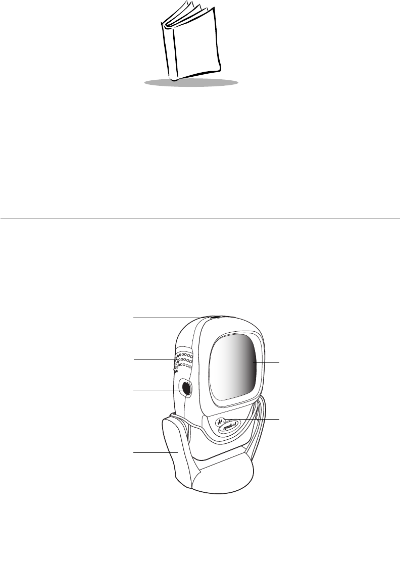
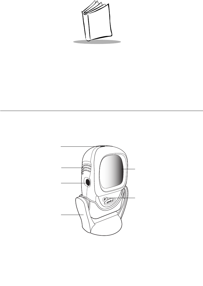
Figure 1-1. Symbol LS9208 Scanner
Decode
LED
Exit Window
Beeper
Hands-Free
Adjustable
Stand
(Optional)
Finger Grips
Single Scan
Line Trigger
and Volume
Control

1-2
Symbol LS9208 Product Reference Guide
The Symbol LS9208 scanner supports the following interfaces:
• Standard RS-232 connection to a host. Proper communications of the scanner with
the host is set up by scanning bar code menus.
• Keyboard Wedge connection to a host. Scanned data is interpreted by your host
as keystrokes.
• International Keyboards supported (for Windows® environment): North
American, German, French, Spanish, Italian, Swedish, UK English, Brazilian/
Portuguese and Japanese.
• International Keyboards supported (for Win XP/2000™ environment): French
Canadian
• International Keyboards supported (for Win 95/98 environment): French
Canadian
• Wand Emulation connection to a host. The scanner is connected to a portable data
terminal, a controller, or host which collects the data as wand data and decodes it.
• Connection to IBM 468X/469X hosts. Proper communications of the scanner with
the IBM terminal is set up by scanning bar codes.
• USB connection to a host. The scanner autodetects a USB host and defaults to the
HID keyboard interface type. Other USB interface types are selectable by scanning
programming bar code menus.
• International Keyboards supported (for Windows environment): North
America, German, French, French International, Spanish, Italian, Swedish,
British, and Japanese.
• Synapse capability which allows you to connect to a wide variety of host systems
using a Synapse and Synapse adapter cable to connect to a host. The scanner
autodetects a Synapse.
Unpacking Your Scanner
Remove the scanner from its packing and inspect it for damage. If the scanner was
damaged in transit, call the Global Customer Interaction Center. See page xv for contact
information. KEEP THE PACKING. It is the approved shipping container and should be
used if you ever need to return your equipment for servicing.
1-3
Getting Started
Setting Up the Scanner
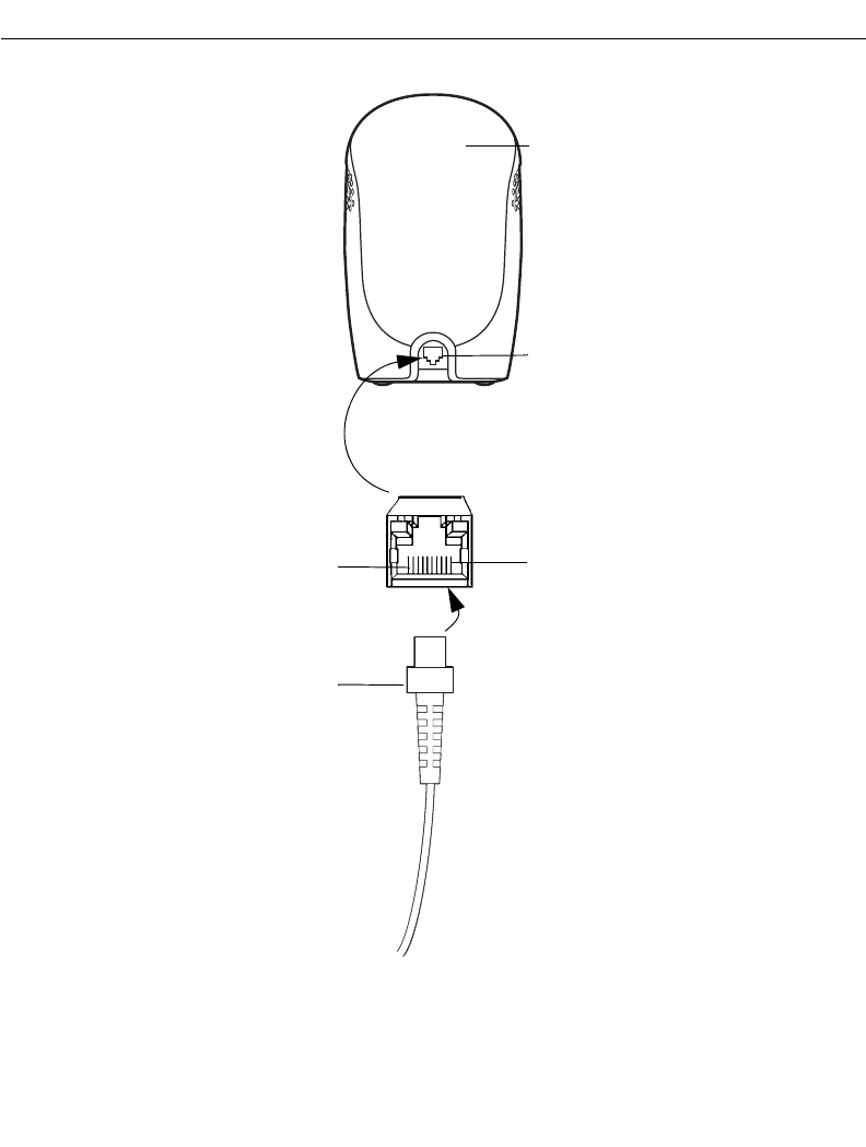
Installing the Interface Cable
1. Connect the interface cable to the host computer.
2. Plug the interface cable modular connector into the interface cable port on the rear
of the Symbol LS9208 (See Figure 1-2.)
3. Push the connector into the housing until a “click” sound is heard. The green LED
lights up and three short high beeps sound, indicating that the scanner is
operational.
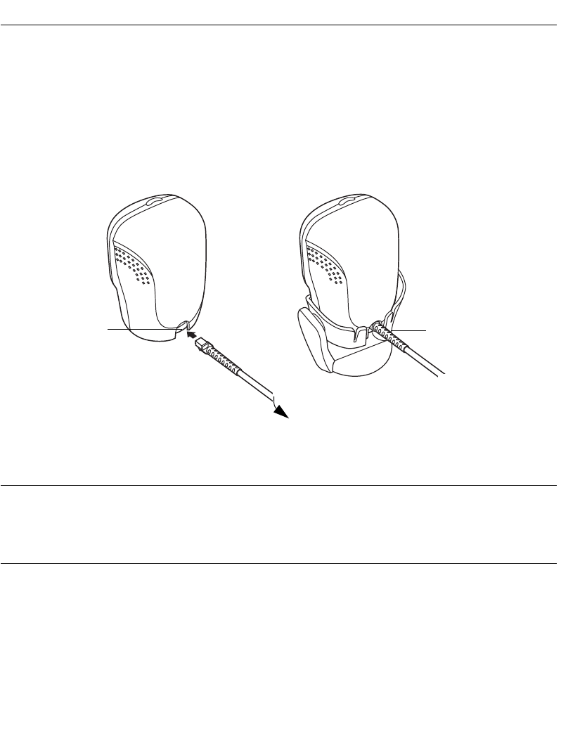
Figure 1-2. Installing the Interface Cable
Note:Different cables are required for different hosts. The connectors
illustrated in each host chapter are examples only. Your connectors
may be different than those illustrated, but the steps to connect your
scanner remain the same.
Interface cable
modular connector
To host
Cable interface
port

1-4
Symbol LS9208 Product Reference Guide
Connecting Power (if required)
If your host does not provide power to the scanner, you will need an external power
connection to the scanner:
1. Connect the interface cable to the back of the scanner, as described in Installing
the Interface Cable on page 1-3.
2. Connect the other end of the interface cable to the host (refer to your host manual
to locate the correct port).
3. Plug the power supply into the power jack on the interface cable.
4. Plug the other end of the power supply into an AC outlet.
Synapse Interface
The auto-detection of a Synapse cable varies in duration depending on the type of Synapse
connection. If a scanner is connected to a host using a Synapse cable then the Auxiliary
Synapse Port connection should be used. In all other cases, where a Synapse cable is used
the default setting is recommended.
Should the user want to disconnect and reconnect the scanner from a Synapse cable that
is connected to a live host, then the "Plug and Play" setting should be used. This setting
should not be changed from the default if an on-board wedge host is enabled.
* Standard Synapse Connection

1-5
Getting Started
Synapse Interface (continued)
Auxiliary Synapse Port Connection
"Plug and Play" Synapse Connection
1-6
Symbol LS9208 Product Reference Guide
Connecting a Synapse Cable Interface
Note:See the Synapse Interface Guide provided with your Synapse cable
for detailed setup instructions.
Symbol’s Synapse Smart Cables enable interfacing to a variety of hosts. The appropriate
Synapse cable has the built-in intelligence to detect the host to which it is connected.
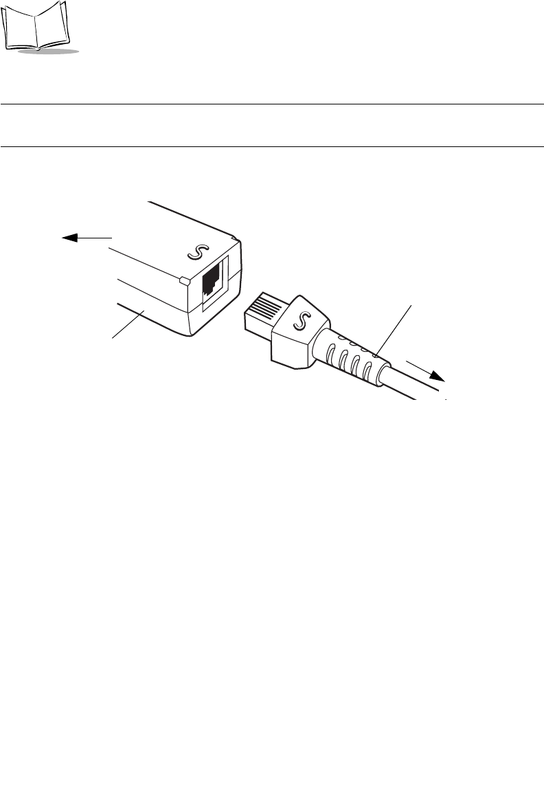
Figure 1-3. Synapse Cable Connection
1. Plug the Synapse adapter cable (p/n 25-32463-xx) into the bottom of the scanner,
as described in Installing the Interface Cable on page 1-3.
2. Align the ‘S’ on the Synapse adapter cable with the ‘S’ on the Synapse Smart Cable
and plug the cable in.
3. Connect the other end of the Synapse Smart Cable to the host.
Configuring Your Scanner
Two methods are available to configure your scanner: using the bar codes included in this
manual, or the 123Scan configuration program.
Refer to Chapter 4, User Preferences for information about programming your scanner
using bar code menus. Refer to Chapter 10, 123Scan to configure your scanner using this
configuration program. A help file is available in the program.
The scanner supports RS-232, IBM 468X/469X, Keyboard Wedge, Wand Emulation, USB,
and Synapse to interface to a host system. Each host specific chapter describes how to set
up each of these connections.
Synapse adapter cable
To scanner
Synapse Smart Cable
To host


1-8
Symbol LS9208 Product Reference Guide
2-1
Chapter 2
Scanning
Introduction
This chapter covers the techniques involved in scanning bar codes, beeper and LED
definitions, and general instructions and tips about scanning.
Figure 2-1. Scanner Parts
Decode
LED
Exit Window
Beeper
Hands-Free
Adjustable
Stand
(Optional)
Finger Grips
Single Scan
Line Trigger
and Volume
Control
2-2
Symbol LS9208 Product Reference Guide
Scanning in Single-Line Mode
Install and program your scanner. (Refer to each host chapter and Chapter 4, User
Preferences, Chapter 11, Symbologies, Chapter 12, Miscellaneous Scanner Options, and
Chapter 13, Advanced Data Formatting for instructions on programming your scanner.) If
you need assistance, contact your local supplier or call the Global Customer Interaction
Center. See page xv for contact information.
1. Ensure all connections are secure. (Refer to the host chapter for your scanner.)
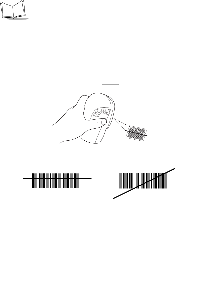
2. Pick up the scanner. Press and then release the trigger. A single scan line
displays.
Figure 2-2. Scanning in Hand-Held Mode
3. Ensure the scan line crosses every bar and space of the symbol.
4. Depress and hold the trigger until either:
a. The scanner reads the bar code. The scanner beeps, the LED flashes and the
laser turns off.
b. The scanner does not read the barcode and the laser turns off.
5. Release the trigger. This causes the aim scan line to reappear. To read another bar
code in single-line mode, repeat steps 2, 3 and 4. This step can be repeated as
often as desired.
6. After a programmable time period, the omni-directional scan pattern displays. This
indicates the scanner is ready to read bar codes without use of the trigger.
7. For more information on beeper definitions, refer to Table 2-1.
RIGHT
012345
WRONG
012345

2-3
Scanning
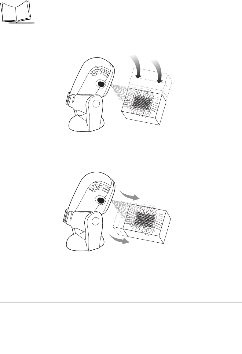
Scanning in Omni Mode
In this mode, an omni scan pattern provides rapid, orientation-free scanning. This scan
pattern is used with either hands-free or hand-held scanning.
To scan a bar code, direct it in toward the window of the scanner (“presentation” scanning,
see Figure 2-7 on page 2-6) or from side to side in a sweeping motion (“swipe” scanning,
see Figure 2-8 on page 2-6).
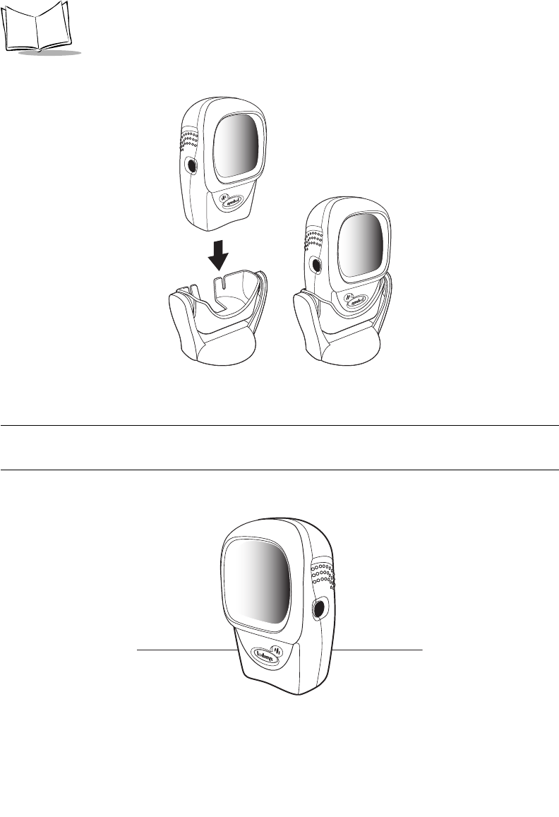
1. Ensure all cable connections are secure.
2. Insert the scanner in the optional hands-free stand by placing the front of the
scanner into the stand’s “cradle” (see Figure 2-3) or place the scanner on a flat
surface (see Figure 2-4).
Note:To mount the optional hands-free adjustable stand, see Mounting
Template on page 2-15.
3. To scan a bar code, present the bar code and ensure the scan lines cross every
bar and space of the symbol. The scan pattern becomes steady when the scanner
detects the bar code. See Figure 2-5 on page 2-5 for scanning in hands-free mode
and Figure 2-6 on page 2-5 for scanning in hand-held mode.
4. Upon successful decode, the scanner beeps and the green LED flashes
momentarily.
2-5
Scanning
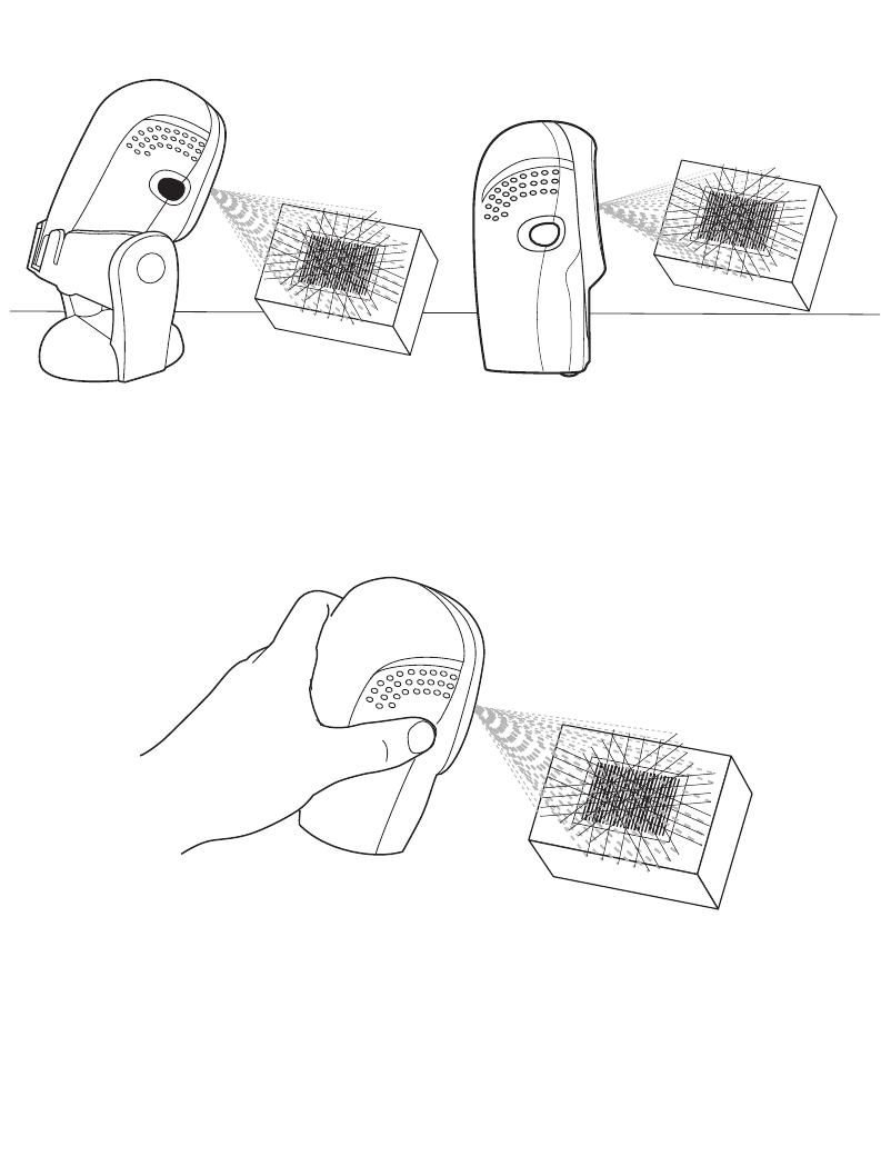
A rastering, 100-line, omni-directional scan pattern provides rapid, orientation-free
scanning. This scan pattern can be used in either hands-free or hand-held mode.
Figure 2-5. Hands-Free Mode
Figure 2-6. Hand-Held Mode
(with stand) (on table-top)
2-6
Symbol LS9208 Product Reference Guide
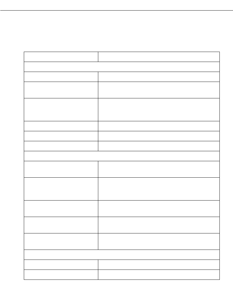
To scan a bar code, present it to the exit window of the scanner (“presentation” scanning)
or move it from side-to-side in a sweeping motion (“swipe” scanning) as show below:
Figure 2-7. “Presentation” scanning
Figure 2-8. “Swipe” scanning
Note:To mount the optional hands-free adjustable stand, see Mounting
Template on page 2-15.
2-7
Scanning
Beeper Definitions
The scanner communicates with the user by emitting different beeper sequences and
patterns. Table 2-1 defines beep sequences that occur during both normal scanning and
while programming the scanner.
Table 2-1. Standard Beeper Definitions
Beeper Sequence Indication
Standard Use
3 short high beeps Power up.
Short high beep A bar code symbol was decoded (if decode beeper
is enabled).
4 long low beeps A transmission error was detected in a scanned
symbol. The data is ignored. This occurs if a unit is
not properly configured. Check option setting.
5 low beeps Conversion or format error.
Lo/hi/lo beep ADF transmit error.
Hi/hi/hi/lo beep RS-232 receive error.
Parameter Menu Scanning
Short high beep Correct entry scanned or correct menu sequence
performed.
Lo/hi beep Input error, incorrect bar code or “Cancel” scanned,
wrong entry, incorrect bar code programming
sequence; remain in program mode.
Hi/lo beep Keyboard parameter selected. Enter value using
bar code keypad.
Hi/lo/hi/lo beep Successful program exit with change in the
parameter setting.
Low/hi/low/hi beep Out of host parameter storage space. Scan Set
Default Parameter on page 4-5.
Code 39 Buffering
Hi/lo beep New Code 39 data was entered into the buffer.
3 long high beeps Code 39 buffer is full.
2-8
Symbol LS9208 Product Reference Guide
Selecting Beeper Volume using Trigger
The scanner emits a short beep when it successfully reads a bar code. The volume of the
beep can be changed either by scanning the appropriate bar code in Beeper Volume on
page 4-7, or by utilizing the trigger as follows:
1. Press and hold the trigger for an extended period of time (approximately 5
seconds). The scanner cycles through three settings (Low, Medium, High) emitting
a 2-beep tone at each setting.
2. To select a particular setting, release the trigger after the desired 2-beep tone is
heard.
Lo/hi/lo beep The Code 39 buffer was erased or there was an
attempt to clear or transmit an empty buffer.
Lo/hi beep A successful transmission of buffered data.
Host Specific
USB only
4 short high beeps Scanner has not completed initialization. Wait
several seconds and scan again.
Scanner gives a power-up
beep after scanning a USB
Device Type.
Communication with the bus must be established
before the scanner can operate at the highest
power level.
This power-up beep occurs
more than once. The USB bus may put the scanner in a state where
power to the scanner is cycled on and off more than
once. This is normal and usually happens when the
PC cold boots.
RS-232 only
1 short high beep A <BEL> character is received and Beep on <BEL>
is enabled.
Table 2-1. Standard Beeper Definitions (Continued)
Beeper Sequence Indication
2-9
Scanning
LED Definitions
In addition to beeper sequences, the scanner communicates with the user using an LED
display. Table 2-2 defines LED flashes that display during scanning.
Table 2-2. Standard LED Definitions
LED Indication
Off No power is applied to the scanner.
Green The scanner is on and “ready to scan.”
Momentary flash A bar code was successfully decoded.
Slow continuous flashing The scanner is in programming mode.
Fast continuous flashing There is a internal problem; the laser is shut off for
regulatory reasons.
2-10
Symbol LS9208 Product Reference Guide
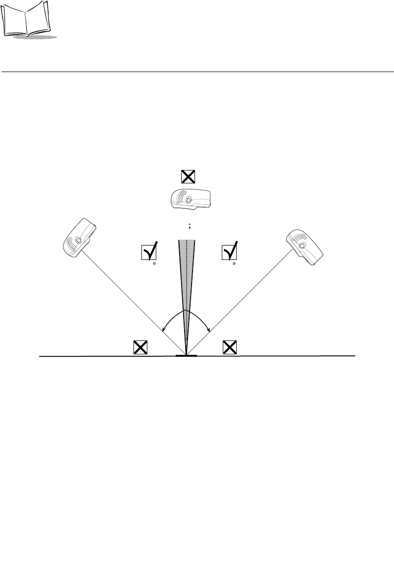
Aiming
Do not hold the scanner directly over the bar code. Laser light reflecting directly back into
the scanner from the bar code is known as specular reflection. This specular reflection can
make decoding difficult.
You can tilt the scanner up to 45° forward or back and achieve a successful decode (Figure
2-9). Simple practice quickly shows what tolerances to work within.
Figure 2-9. Maximum Tilt Angles and Dead Zone
Bar
Code
Specular
Reflection
-
+ 4
4545
2-11
Scanning
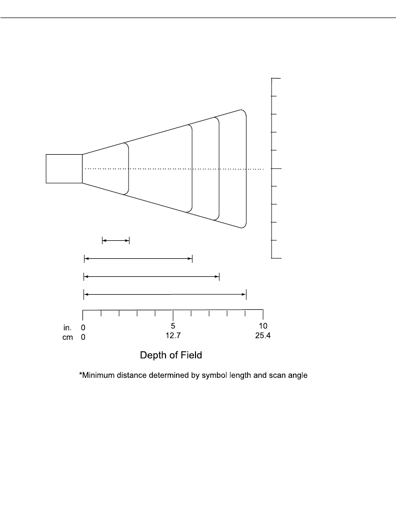
Decode Zone
Figure 2-10. Symbol LS9208 Decode Zone
LS 9208
5 mil
1.0 2.5
0
5
0
12.7
12.75
in. cm
W
i
d
t
h
o
f
F
i
e
l
d
Note: Typical performance at 73.4 F (23 C)
on high quality symbols.
9.0
7.8 mil (60%)
10.4 mil (80%)
6.0
7.5
13 mil 100% UPC
0
0
0

2-12
Symbol LS9208 Product Reference Guide
Integrated Electronic Article Surveillance (EAS)
Deactivation Antenna for Checkpoint EAS Systems
The Symbol LS9208's optional EAS deactivation feature includes an integrated RF
antenna which, when attached to a Checkpoint Systems, Inc. RF-EAS deactivation system,
supports deactivation of RF-EAS security labels while scanning a product at the Point-of-
Sale. This allows the merchandise to be removed from the store without activating the
security alarm.
Note:Please contact your local Checkpoint representative to help connect
the EAS deactivation system to insure proper operation.
EAS Deactivation Range
EAS Deactivation Range depends upon several factors including:
•EAS Tags. EAS tags are produced by several different manufacturers, each with
a different performance level. This variance in performance can also vary the
deactivation range.
•Cable. The length of the EAS antenna cable wire is directly related to deactivation
range. The longer the EAS deactivation antenna wires are, the more signal loss
there is, which decreases EAS deactivation range.
•Calibration of the Checkpoint RF-EAS Deactivation System. There are several
adjustments that can be made on the Checkpoint Deactivation System side.
Please contact Checkpoint Systems, Inc. for details.
•Check Stand Construction. Check stand construction also affects EAS
deactivation range. The RF-EAS signal can be dampened, or severely reduced if
there is too much metal or wood blocking the RF signal.
Note:Please contact your local Checkpoint representative to help connect
the EAS deactivation system to insure proper operation.

2-13
Scanning
Symbol LS9208 Host Interface Cables and EAS
The Symbol LS9208 utilizes Symbol's universal scanner cables, which include several
varieties that incorporate RF-EAS deactivation signal wires. Universal EAS scanner cables
are only available as Straight Cables. No coiled EAS cables are available for use with EAS.
Coiled cables are longer than straight cables, which results in RF-EAS signal loss. As a
coiled cable is stretched, the EAS deactivation range will further be reduced. This is not
acceptable operation for EAS security systems.
Different Checkpoint EAS Models
There are several Checkpoint EAS systems available. The Symbol LS9208 is specified to
work with CounterPoint IV, V, VI, VII & IX models from Checkpoint Systems, Inc.
Checkpoint Contact Information
Checkpoint Headquarters (New Jersey): 800-257-5540.
Outside the United States: +1-856-848-1800.

2-14
Symbol LS9208 Product Reference Guide
2-15
Scanning
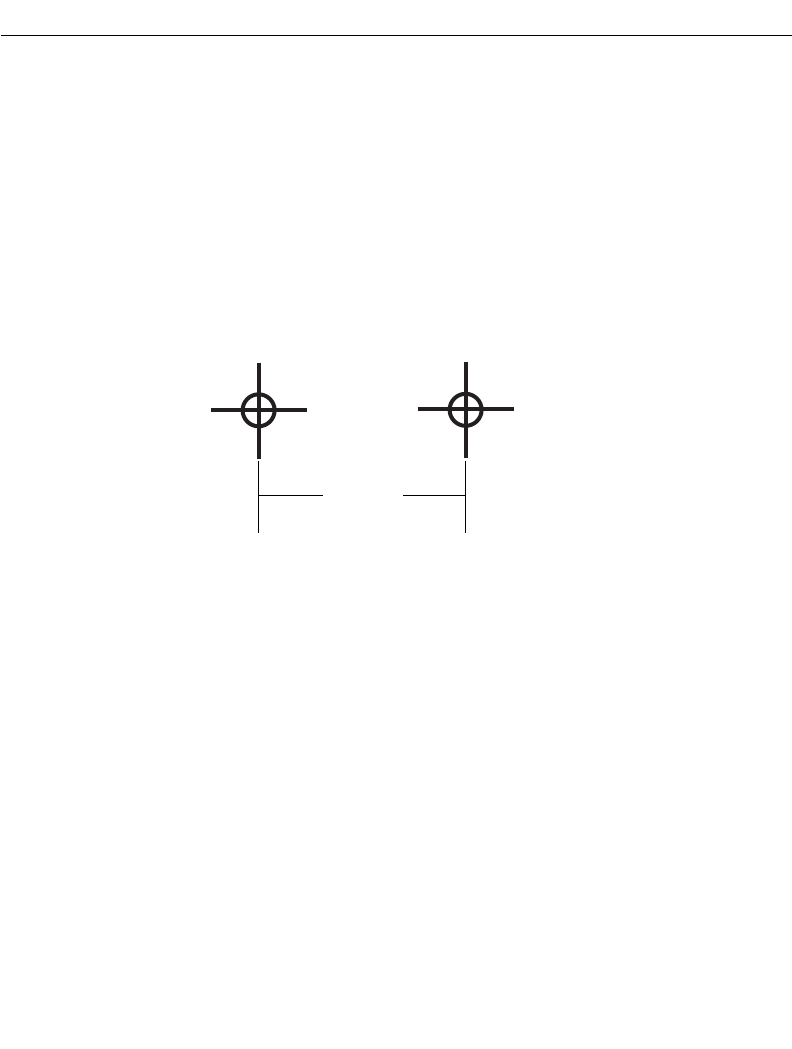
Mounting Template
Use the template to mount the optional hands-free stand on a flat surface. Two #6-32
screws, 5/8 in. long, are recommended.
1.442 in.
3.663 cm

2-16
Symbol LS9208 Product Reference Guide

3-1
Chapter 3
Maintenance and Technical Specifications
Introduction
This chapter covers suggested scanner maintenance, troubleshooting, technical
specifications, and signal descriptions (pinouts).
Maintenance
Cleaning the exit window is the only maintenance required. A dirty window may affect
scanning accuracy.
• Do not allow any abrasive material to touch the window.
• Remove any dirt particles with a damp cloth.
• Wipe the window using a tissue moistened with ammonia/water.
• Do not spray water or other cleaning liquids directly into the window.
3-2
Symbol LS9208 Product Reference Guide
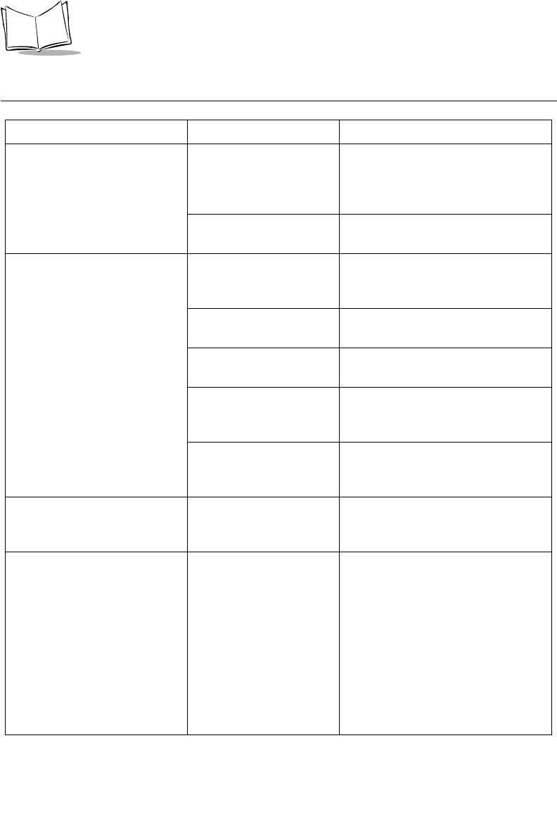
Troubleshooting
Problem Possible Causes Possible Solutions
The omni-line scan pattern
does not display when you
follow the directions for
installing the interface cable on
1-3
No power to the scanner. Ensure the host has power, and is on.
If the scanner uses a separate power
supply, ensure it’s connected to a
working AC outlet.
Interface cable is not
properly connected. Check for loose cable connections.
Scan line(s) display, but bar
code cannot be read. Scanner is not
programmed to read the
bar code type.
Ensure scanner is programmed to
read the bar code type you are
scanning.
Bar code is damaged. Try scanning other bar codes of the
same bar code type.
Bar code is too far from
scanner. Move the bar code closer to the
scanner.
Triggered scanning is
being used incorrectly. Press the trigger to activate
decoding. Follow directions on page
2-2.
The host has disabled
scanning or overridden
parameter settings.
See the technical person in charge of
scanning.
Bar code is decoded, but not
transmitted to the host. Scanner is not
programmed for the
correct host type.
Scan the appropriate host type bar
code.
Scanned data is incorrectly
displayed on the host. Scanner is not
programmed to work with
the host. Check scanner
host type parameters or
editing options.
• Ensure proper host is selected.
• For RS-232, ensure the scanner’s
communication parameters match
the host’s settings.
• For keyboard wedge, ensure
scanner is programmed with the
correct country code and that the
CAPS LOCK key is off.
• Ensure editing options (e.g.,
UPCE-to-UPCA Conversion) are
properly programmed.

3-3
Maintenance and Technical Specifications
Note:If after performing these checks the symbol still does not scan,
contact your distributor or call the Global Customer Interaction
Center. See page xv for contact information.
Although the green Power LED
is on, the scanner does not
produce the omni-directional
scan pattern.
The scanner has gone
into the Low Power “Shut
Down” Mode.
Press the trigger to awaken the unit,
or change the “Low Power Blink”
parameter on page 4-11.
Problem Possible Causes Possible Solutions
3-4
Symbol LS9208 Product Reference Guide
Technical Specifications
Table 3-1. Technical Specifications
Item Description
Physical Characteristics
Dimensions:
without stand: Height
Width
Depth
with stand: Height
Width
Depth
5.51 in. (14 cm)
3.49 in. (8.8 cm)
2.96 in. (7.5 cm)
7.18 in. (18.24 cm)
4.83 in. (12.27 cm)
3.73 in. (9.47 cm)
Weight Scanner only: 10.2 oz/320 g
With adjustable stand: 21.5 oz/670 g
Power Source Power drawn from Host terminal or external power
supply; depends on Host type.
Voltage 5.0 VDC ± 10%
Nominal Current 390 mA
Power 2 watts
Mounting Options Adjustable multi-mount stand
Color Cash Register White and Twilight Black
Performance Characteristics
Light Source 650nm visible laser diode
Yaw Tolerance (Typical)1Omnidirectional: ± 50°
Single scan line: ± 50°
Pitch Tolerance (Typical)1Omnidirectional: ± 50°
Single scan line: ± 60°
Roll Tolerance (Typical)1Omnidirectional: 0 to 360°
Single scan line: ± 40°
Print Contrast 25% minimum reflective difference
1Refers to 100% UPC bar code (80% contrast) located 4 in./10 cm from the scanner nose.

3-5
Maintenance and Technical Specifications
Scan Patterns Omnidirectional: 20 interlocking lines,
5 scan lines,
4 lines per angle rastering @ 5Hz
Single scan line capability
Scan Rate Omnidirectional: 1500 scans/second
Single scan line: 75 scans/second
Depth of Field 0-9 in./0-22.9 cm @ 13 mil (100% UPC/EAN)
Nominal Working Range 5 mil: (38%) 1 to 2.5 in./ 2.5 to 6.4 cm
7.8 mil: (60%) 0 to 6 in./ 0 to 15.2 cm
10.4 mil: (80%) 0 to 7.5 in./ 0 to 19 cm
13 mil: (100%) 0 to 9 in./ 0 to 22.9 cm
Width of Field 1.6 in. (40 mm) @ Face
6.7 in. (170 mm) @ 9 in.
Minimum Resolution 5 mil
Decode Capability UPC/EAN/JAN, UPC/EAN with Supplementals, UCC/
EAN 128, Code 128, ISBT 128, Code 39, Code 39
Trioptic, Interleaved 2 of 5, Discrete 2 of 5, Code 93,
Code 11, Codabar, MSI, RSS Variants
Interfaces Supported USB, RS 232, IBM® 468X/9X,
Keyboard Wedge, Wand and Synapse™ (allows
connectivity to virtually every POS host type)
User Environment
Operating Temperature 32° to 104°F (0° to 40°C)
Storage Temperature -40° to 158°F (-40° to 70°C)
Humidity 5% to 95% (non-condensing)
Drop Specifications Functions normally after repeated 4 ft (1.2m) drops to
concrete
Table 3-1. Technical Specifications (Continued)
Item Description
3-6
Symbol LS9208 Product Reference Guide
Ambient Light Immunity Immune to normal artificial indoor and natural outdoor
(direct sunlight) lighting conditions.
Fluorescent, Incandescent, Mercury Vapor and
Sodium Vapor: 450 Ft Candles (4,844 Lux)
Sunlight: 8000 Ft Candles (86,111 Lux)
EAS Support Optional Checkpoint Electronic Article
Surveillance EAS
Regulatory
Electrical Safety Certified to UL 1950, CSA C22.2 No. 950 EN60825
Laser Safety CDRH Class IIa Laser Product
IEC 60825 Class 1 Laser Product
EMC CISPR B, FCC B
Table 3-1. Technical Specifications (Continued)
Item Description
3-7
Maintenance and Technical Specifications
Scanner Signal Descriptions
Figure 3-1. Scanner Cable Pinouts
PIN 10
Back of scanner
PIN 1
Interface cable
modular connector
Cable interface port
3-8
Symbol LS9208 Product Reference Guide
The signal descriptions in Table 3-2 apply to the connector on the scanner and are for
reference only.
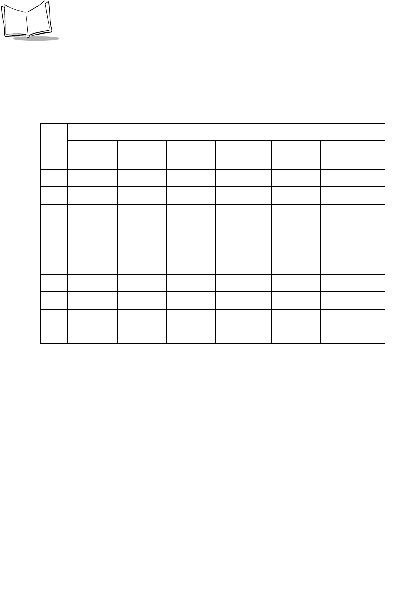
Table 3-2. Scanner Signal Pin-outs
Symbol LS9208
Pin IBM Synapse RS-232 Keyboard
Wedge Wand USB
1Reserved SynClock Reserved Reserved Reserved Jump to Pin 6
2Power Power Power Power Power Power
3Ground Ground Ground Ground Ground Ground
4IBM_A(+) Reserved TxD KeyClock DBP Reserved
5Reserved Reserved RxD TermData CTS D +
6IBM_B(-) SynData RTS KeyData RTS Jump to Pin 1
7Reserved Reserved CTS TermClock Reserved D -
8Reserved Reserved Reserved Reserved Reserved Reserved
9Reserved Reserved Reserved Reserved Reserved Reserved
10 Reserved Reserved Reserved Reserved Reserved Reserved

4-1
Chapter 4
User Preferences
Introduction
You have the option to program the Symbol LS9208 scanner to perform various functions,
or activate different features. This chapter describes each user preference feature and
provides the programming bar codes necessary for selecting these features for your
Symbol LS9208 scanner. Before programming, follow the instructions in Chapter 1, Getting
Started.
The Symbol LS9208 is shipped with the settings shown in the User Preferences Default
Table on page 4-3 (also see Appendix A, Standard Default Parameters for all host device
and miscellaneous scanner defaults). If the default values suit your requirements,
programming may not be necessary.
Features values are set by scanning single bar codes or short bar code sequences. The
settings are stored in non-volatile memory and are preserved even when the scanner is
powered down.

4-2
Symbol LS9208 Product Reference Guide
If you are not using a Synapse or USB cable you must select a host type (see each host
chapter for specific host information). After you hear the power-up beeps, select a host
type. This only needs to be done once, upon the first power-up when connected to a new
host.
To return all features to their default values, all you need to do is scan the Set All Defaults
bar code on page 4-5. Throughout the programming bar code menus, default values are
indicated with asterisks (*).
Scanning Sequence Examples
In most cases you need only scan one bar code to set a specific parameter value. For
example, if you want to set the beeper tone to high, simply scan the High Frequency
(beeper tone) bar code listed under Beeper Tone on page 4-6. The scanner issues a short
high beep and the LED turns green, signifying a successful parameter entry.
Other parameters, such as specifying Serial Response Time-Out or setting Data
Transmission Formats, require that you scan several bar codes. Refer to Host Serial
Response Time-out on page 6-21 and Scan Data Options on page 12-9 for descriptions of
this procedure.
Errors While Scanning
Unless otherwise specified, if you make an error during a scanning sequence, just re-scan
the correct parameter.
*High Frequency Feature/Option
* Indicates Default

4-3
User Preferences
User Preferences Default Parameters
Table 4-1 lists the defaults for user preferences parameters. If you wish to change any
option, scan the appropriate bar code(s) provided in the User Preferences section
beginning on page 4-5.
Note:See Appendix A, Standard Default Parameters for all user
preferences, hosts, symbologies, and miscellaneous default
parameters.
Table 4-1. User Preferences Default Table
Parameter Default Page
Number
User Preferences
Set Default Parameter All Defaults 4-5
Beeper Tone High 4-6
Beeper Volume High 4-7
Volume Change Trigger Delay 5.0 Sec 4-8
Laser On Time 3.0 Sec 4-9
Beep After Good Decode Enable 4-10
Low Power Blink Blink 4-11
Scan Pattern Mode Rastering 4-12
Single-Line Aim Duration 2 sec 4-13
Time-out Between Same Symbol 0.6 sec 4-15
Time-out Between Different Symbols 0.2 sec 4-15
Time Delay to Low Power Mode 30 Minutes 4-16


4-6
Symbol LS9208 Product Reference Guide
Beeper Tone
To select a decode beep frequency (tone), scan the Low Frequency, Medium Frequency,
or High Frequency bar code.
Low Frequency
Medium Frequency
*High Frequency

4-7
User Preferences
Beeper Volume
To select a beeper volume, scan the Low Volume, Medium Volume, or High Volume bar
code.
Low Volume
Medium Volume
*High Volume

4-8
Symbol LS9208 Product Reference Guide
Volume Change Trigger Delay
The volume on the Symbol LS9208 scanner is adjusted by pressing and holding the trigger
for a certain amount of time, after which the scanner changes the volumes, and beeps with
the new volume.
The parameters below control the length of time needed to hold the trigger before the
volume is adjusted.
Volume Trigger Duration 3 sec
*Volume Trigger Duration 5 sec
Volume Trigger Duration 7 sec

4-9
User Preferences
Laser On Time
This parameter sets the maximum time that decode processing continues during a scan
attempt. It is programmable in 0.1 second increments from 0.5 to 10 seconds. The default
Laser On Time is 3.0 seconds.
To set a Laser On Time, scan the bar code below. Next, scan two numeric bar codes
beginning on page D-1 in Appendix D that correspond to the desired on time. Single digit
numbers must have a leading zero. For example, to set an On Time of 0.5 seconds, scan
the bar code below, then scan the “0” and “5” bar codes. If you make an error, or wish to
change your selection, scan Cancel on page D-5.
Laser On Time
4-10
Symbol LS9208 Product Reference Guide
Beep After Good Decode
Scan a bar code below to select whether or not the scanner beeps after a good decode. If
Do Not Beep After Good Decode is selected, the beeper still operates during parameter
menu scanning and indicates error conditions.
*Beep After Good Decode
(Enable)
Do Not Beep After Good Decode
(Disable)

4-11
User Preferences
Low Power Blink
After a period of inactivity, the scanner will go into a reduced power mode. This parameter
controls how aggressively power is conserved, and therefore determines the method of
waking the scanner up.
If “Low Power - Blink Mode” is selected, then the scanner (after a period of inactivity) will
blink infrequently to save power. To restore the scanner to full power mode, the user must
simply use the scanner by presenting a barcode.
If “Motor and Laser Shut Down” is selected, then the scanner (after a period of inactivity)
will turn off the motor and laser, but leave the green Power LED lit. The user must then
depress the trigger to awaken the scanner to its full power mode.
*Low Power - Blink Mode
Low Power - Shut Down
4-12
Symbol LS9208 Product Reference Guide
Scan Pattern Mode
The Symbol LS9208 has a very aggressive scan pattern that is not only omnidirectional,
but also raster. If a static omnidirectional pattern is desired, scan the “Omnidirectional
Pattern” parameter below to change the scan pattern.
*Rastering Omnidirectional Pattern
Omnidirectional Pattern

4-13
User Preferences
Single-Line Aim Duration
The Symbol LS9208 can enter the single-line scan mode by tapping the trigger. Once in
this mode, each trigger pull will attempt to decode the barcode in front of the scanner. After
a period of inactivity while the trigger is not pressed, the scanner will revert to the
omnidirectional pattern.
This parameter controls the length of the period of inactivity in single-line mode before the
scanner reverts to the omnidirectional pattern.
*Aim Duration 2 sec
Aim Duration 3 sec

4-14
Symbol LS9208 Product Reference Guide
Single-Line Aim Duration (Continued)
Aim Duration 4 sec
Aim Duration 5 sec

4-15
User Preferences
Timeout Between Decodes
Timeout Between Decodes, Same Symbol
This parameter sets the minimum time between decodes of different symbols. It is
programmable in 0.1-second increments from 0.0 to 9.9 seconds. Setting this above 0.4
seconds is recommended.) The default for this parameter is 0.6 seconds.
Scan the bar code below to select a new timeout. Next, scan two numeric bar codes
beginning in Numeric Bar Codes on page D-1 that correspond to the desired timeout.
Single digit numbers must have a leading zero. For example, to set a timeout of 0.5
seconds, scan the bar code below, then scan the “0” and “5” bar codes. If you make an
error, or wish to change your selection, scan Cancel on page D-5.
Timeout Between Same Symbol
Timeout Between Decodes, Different Symbol
This parameter sets the minimum time between decodes of different symbols. It is
programmable in 0.1-second increments from 0.0 to 9.9 seconds. The default for this
parameter is 0.2 seconds.
Scan the bar code below to select a new timeout. Next, scan two numeric bar codes
beginning in Numeric Bar Codes on page D-1 that correspond to the desired timeout.
Single digit numbers must have a leading zero. For example, to set a timeout of 0.5
seconds, scan the bar code below, then scan the “0” and “5” bar codes. If you make an
error, or wish to change your selection, scan Cancel on page D-5.
Timeout Between Different Symbol

4-16
Symbol LS9208 Product Reference Guide
Time Delay to Low Power Mode
This parameter sets the time that the scanner remains active after any scanning activity.
Scan one of the four options. Depending on the selection, the scanner enters a sleep mode
15, 30, 60 or 90 minutes after the last attempted decode. To awaken the scanner, please
refer to the explanation of the Low Power Blink parameter on page 4-11.
15 Minutes
*30 Minutes

4-17
User Preferences
Time Delay to Low Power Mode (Continued)
60 Minutes
90 Minutes

4-18
Symbol LS9208 Product Reference Guide
Time Delay to Low Power Mode (Continued)
Linear UPC/EAN Decode
This option applies to code types containing two adjacent blocks (e.g., UPC-A, EAN-8,
EAN-13). When enabled, a bar code is transmitted only when both the left and right blocks
are successfully decoded within one laser scan. Enable this option when bar codes are in
proximity to each other.
Enable Linear UPC/EAN Decode
Extended (127.5 Hours)

4-19
User Preferences
Linear UPC/EAN Decode (Continued)
*Disable Linear UPC/EAN Decode

4-20
Symbol LS9208 Product Reference Guide
5-1
Chapter 5
Keyboard Wedge Interface
Introduction
This chapter covers Keyboard Wedge interface information for setting up your scanner.
This interface type is used to attach the scanner between the keyboard and host computer.
The scanner translates the bar code data into keystrokes. The host computer accepts the
keystrokes as if they originate from the keyboard.
This mode of operation allows adding bar code reading functionality to a system designed
for manual keyboard input. In this mode the keyboard keystrokes are simply passed
through.
Throughout the programming bar code menus, default values are indicated with asterisks
(*).
*North American Feature/Option
* Indicates Default
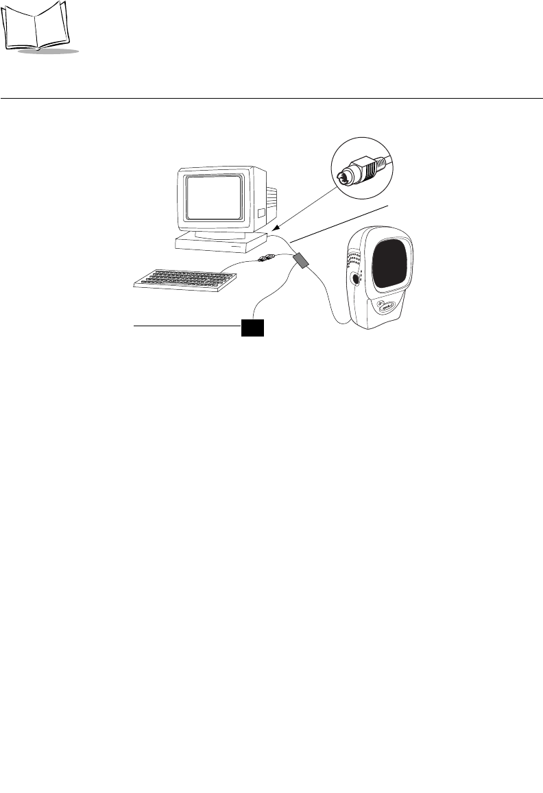
5-2
Symbol LS9208 Product Reference Guide
Connecting a Keyboard Wedge Interface
Figure 5-1. Keyboard Wedge Connection with Y-cable
To connect the Keyboard Wedge Y-cable:
1. Switch off the host and unplug the keyboard connector.
2. Attach the modular connector of the Y-cable to the cable interface port on the
scanner. (See Installing the Interface Cable on page 1-3.)
3. Connect the round male DIN host connector of the Y-cable to the keyboard port on
the host device.
4. Connect the round female DIN keyboard connector of the Y-cable to the keyboard.
5. If needed, attach the optional power supply to the connector in the middle of the Y-
cable.
6. Ensure that all connections are secure.
7. Switch on your host system.
8. Scan the appropriate bar codes in this chapter to configure the scanner.
Power supply
(if needed)
Y-cable
Male DIN Keyboard
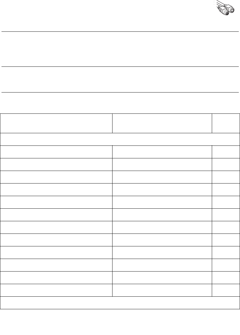
5-3
Keyboard Wedge Interface
Keyboard Wedge Default Parameters
Table 5-1 lists the defaults for Keyboard Wedge host parameters. If you wish to change any
option, scan the appropriate bar code(s) provided in the Keyboard Wedge Host Parameters
section beginning on page 5-4.
Note:See Appendix A, Standard Default Parameters for all user
preferences, hosts, symbologies, and miscellaneous default
parameters.
Table 5-1. Keyboard Wedge Host Default Table
Parameter Default Page
Number
Keyboard Wedge Host Parameters
Keyboard Wedge Host Type IBM PC/AT & IBM PC Compatibles15-4
Country Types (Country Codes) North American 5-6
Ignore Unknown Characters Send Bar Codes 5-10
Keystroke Delay No Delay 5-11
Intra-Keystroke Delay Disable 5-12
Alternate Numeric Keypad Emulation Disable 5-13
Caps Lock On Disable 5-14
Caps Lock Override Disable 5-15
Convert Wedge Data No Convert 5-16
Function Key Mapping Disable 5-17
FN1 Substitution Disable 5-18
Send Make Break Disable 5-19
1User selection is required to configure this interface and this is the most common selection.
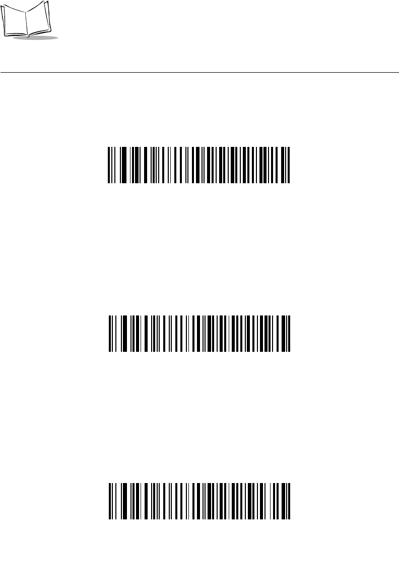
5-4
Symbol LS9208 Product Reference Guide
Keyboard Wedge Host Types
Keyboard Wedge Host Types
Select your keyboard wedge host by scanning one of the bar codes below.
IBM PC/AT & IBM PC Compatibles1
IBM PS/2 (Model 30)
IBM AT NOTEBOOK
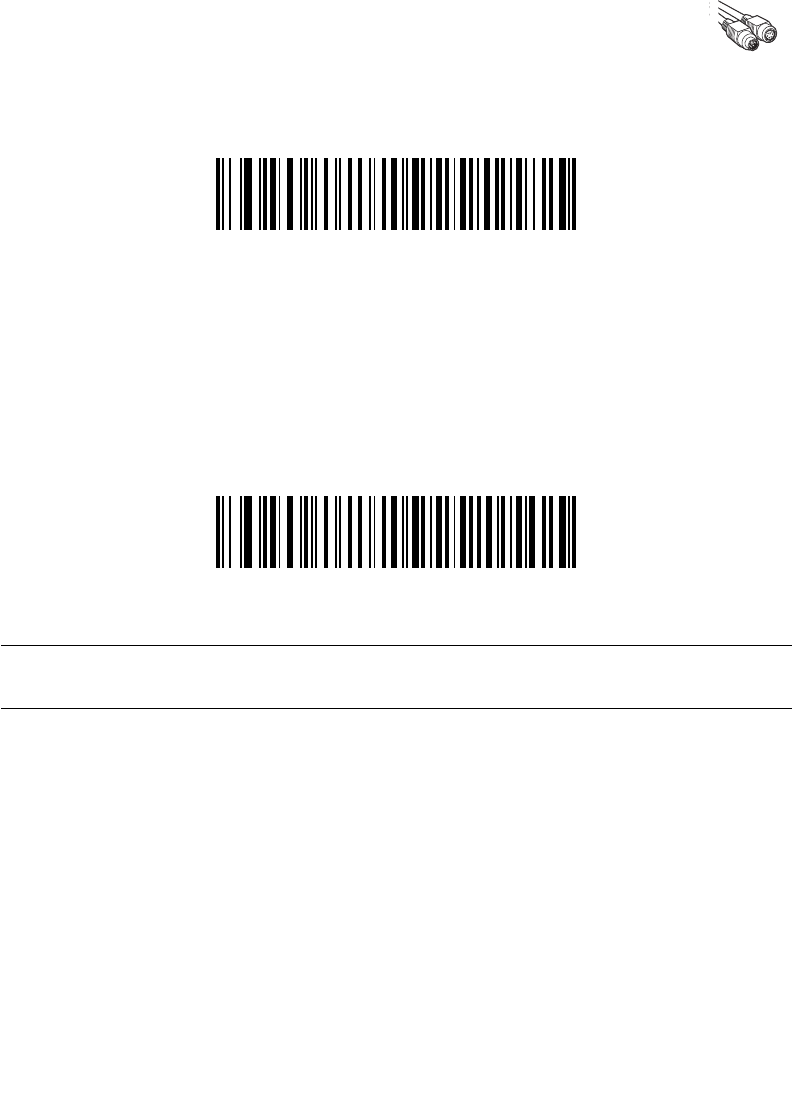
5-5
Keyboard Wedge Interface
Keyboard Wedge Host Types (Continued)
IBM XT
NCR 7052
Note:1User selection is required to configure this interface and this is the
most common selection.


5-7
Keyboard Wedge Interface
Keyboard Wedge Country Types (Continued)
French Canadian Win 95/98
French Canadian Windows XP/2000
Spanish Windows

5-8
Symbol LS9208 Product Reference Guide
Keyboard Wedge Country Types (Continued)
Italian Windows
Swedish Windows
UK English Windows

5-9
Keyboard Wedge Interface
Keyboard Wedge Country Types (Continued)
Japanese Windows
Brazilian/Portuguese Windows
5-10
Symbol LS9208 Product Reference Guide
Ignore Unknown Characters
Unknown characters are characters the host does not recognize. When Send Bar Codes
With Unknown Characters is selected, all bar code data is sent except for unknown
characters, and no error beeps sound on the scanner. When Do Not Send Bar Codes With
Unknown Characters is selected, bar code data is sent up to the first unknown character
and then an error beep will sound on the scanner.
*Send Bar Codes With Unknown
Characters
Do Not Send Bar Codes With Unknown Characters

5-11
Keyboard Wedge Interface
Keystroke Delay
This is the delay in milliseconds between emulated keystrokes. Scan a bar code below to
increase the delay when hosts require a slower transmission of data.
*No Delay
Medium Delay (20 msec)
Long Delay (40 msec)

5-12
Symbol LS9208 Product Reference Guide
Intra-Keystroke Delay
When enabled, an additional delay is inserted between each emulated key depression and
release. This sets the Keystroke Delay parameter to a minimum of 5 msec as well.
Enable
*Disable

5-13
Keyboard Wedge Interface
Alternate Numeric Keypad Emulation
This allows emulation of most other country keyboard types not listed in Keyboard Wedge
Country Types (Country Codes) on page 5-6 in a Microsoft operating system environment.
Enable Alternate Numeric Keypad
*Disable Alternate Numeric Keypad
5-14
Symbol LS9208 Product Reference Guide
Caps Lock On
When enabled, the scanner emulates keystrokes as if the Caps Lock key is always
pressed.
Enable Caps Lock On
*Disable Caps Lock On
5-15
Keyboard Wedge Interface
Caps Lock Override
When enabled, on AT or AT Notebook hosts, the keyboard ignores the state of the Caps
Lock key. Therefore, an ‘A’ in the bar code is sent as an ‘A’ no matter what the state of the
keyboard’s Caps Lock key.
Enable Caps Lock Override
*Disable Caps Lock Override
Note:If both Caps Lock On and Caps Lock Override are enabled, Caps
Lock Override takes precedence.
5-16
Symbol LS9208 Product Reference Guide
Convert Wedge Data
When enabled, the scanner will convert all bar code data to the selected case.
Convert to Upper Case
Convert to Lower Case
*No Convert

5-17
Keyboard Wedge Interface
Function Key Mapping
ASCII values under 32 are normally sent as a control-key sequences (see Table 7-2 on
page 7-20). When this parameter is enabled, the keys in bold are sent in place of the
standard key mapping. Table entries that do not have a bold entry remain the same whether
or not this parameter is enabled.
Enable
*Disable


5-19
Keyboard Wedge Interface
Send Make Break
When enabled, the scan codes for releasing a key are not sent.
*Send Make and Break Scan Codes
Send Make Scan Code Only
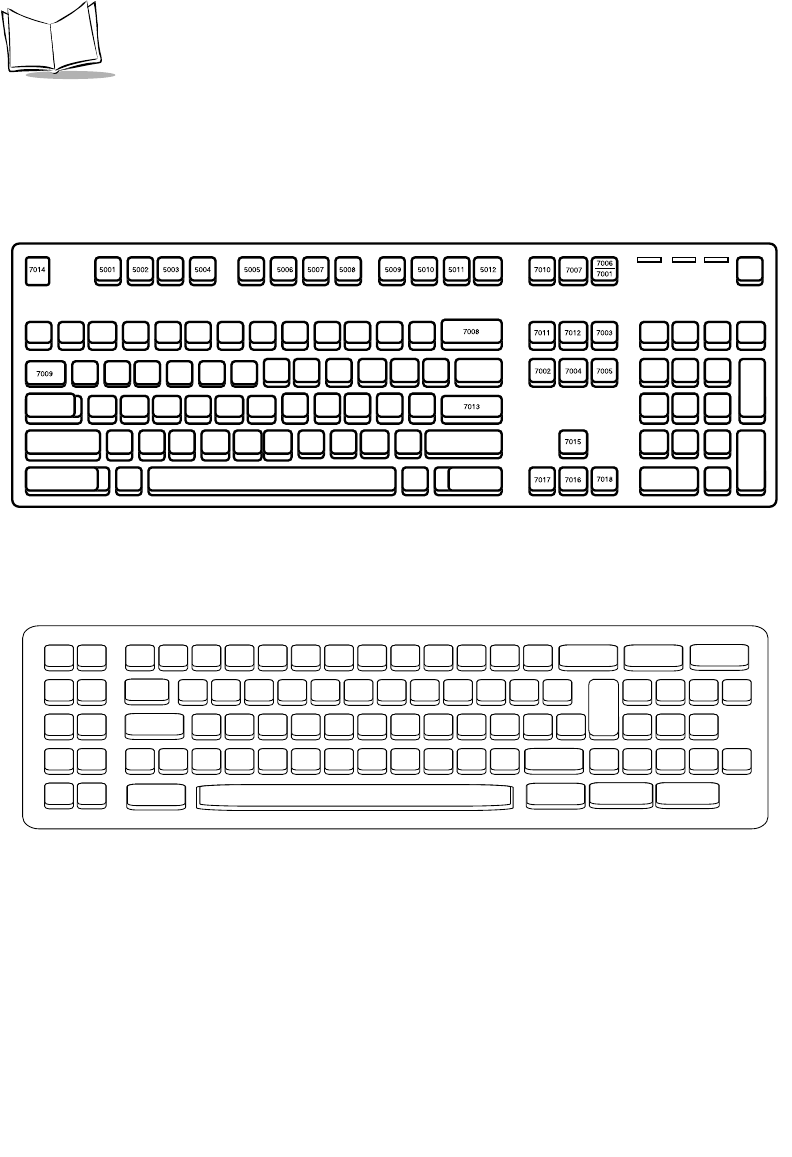
5-20
Symbol LS9208 Product Reference Guide
Keyboard Maps
The following keyboard maps are provided for prefix/suffix keystroke parameters. To
program the prefix/suffix values, see the bar codes on page 12-5.
Figure 5-2. IBM PS2 Type Keyboard
.
Figure 5-3. IBM PC/XT
5001 5002
5003 5004
5005 5006
5007 5008
5009 5010
7009
7014 7008
7013
7012
7004
7011 7002
7003
7006
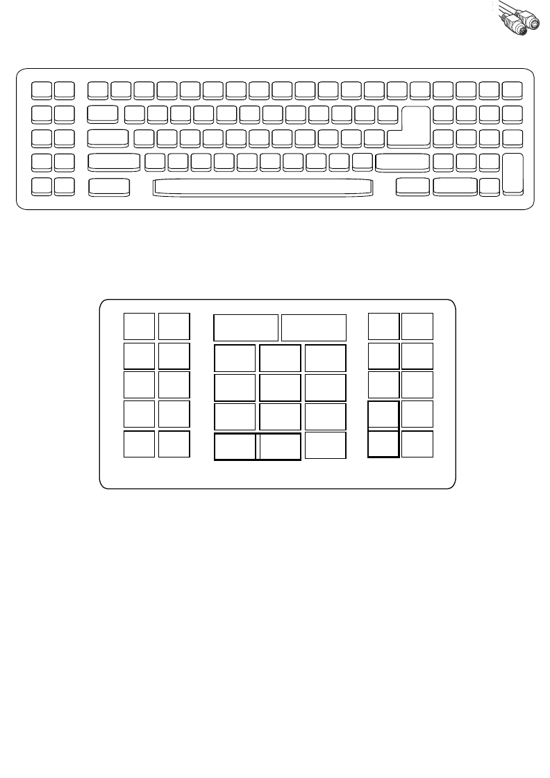
5-21
Keyboard Wedge Interface
Figure 5-4. IBM PC/AT
Figure 5-5. NCR 7052 32-KEY
5001 5002
5003 5004
5005 5006
5007 5008
5009 5010
7009
7008
7013
7012
7004
7011
7003
7002
7014
5007 5008
5010
5002
5003 5004
5005 5006
1046
1045
5014
1043
5013
5015
5016
5018
5019
5001
5017
7013
5011
(7013 if double key)
(1048 if double key)
1048 5012
5009
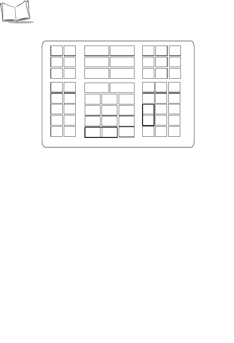
5-22
Symbol LS9208 Product Reference Guide
Figure 5-6. NCR 7052 58-KEY
5007 5008
5010
5002
5003 5004
5005 5006
1046
1045
5014
1043
5013
5015
5016
5018
5019
1086
1087
1088
1089
1090
5001
1066
1072 1073
1079 1080
1065 1070
1076 1077
1083 1084
1071
1078
1085
1069
5017
7013
5011
1082
1075
1068
1067
(1043 if double key)
(1048 if double key)
1048 5012
5009
1074
1081
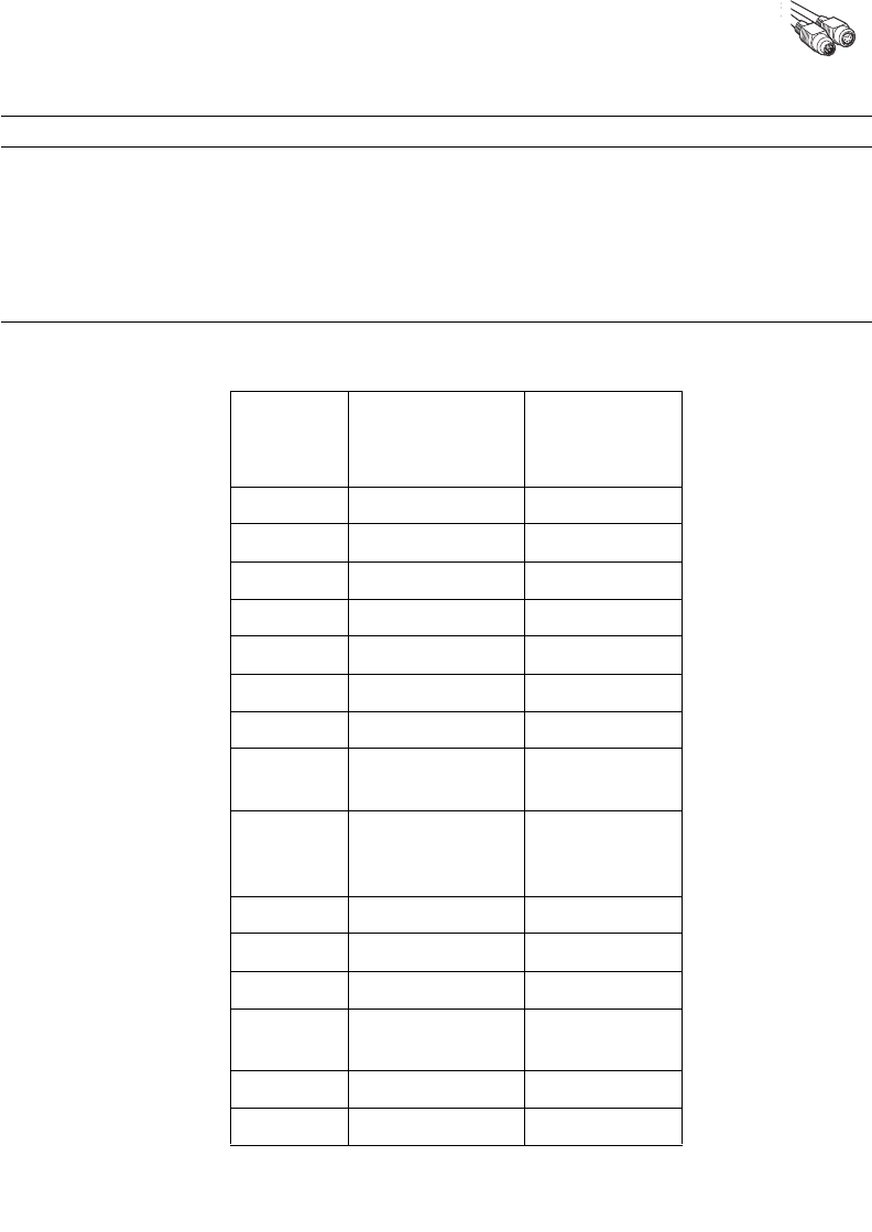
5-23
Keyboard Wedge Interface
ASCII Character Set
Note:Code 39 Full ASCII interprets the bar code special character
($ + % /) preceding a Code 39 character and assigns an ASCII
character value to the pair. For example, when Code 39 Full ASCII
is enabled and a +B is scanned, it is interpreted as b, %J as ?, and
%V as @. Scanning ABC%I outputs the keystroke equivalent of
ABC >.
Table 5-2. Keyboard Wedge ASCII Character Set
ASCII
Value
Full ASCII Code
39 Encode Char.
Keystroke
1001 $A CTRL A
1002 $B CTRL B
1003 $C CTRL C
1004 $D CTRL D
1005 $E CTRL E
1006 $F CTRL F
1007 $G CTRL G
1008 $H CTRL H/
BACKSPACEa
1009 $I CTRL I/
HORIZONTAL
TAB1
1010 $J CTRL J
1011 $K CTRL K
1012 $L CTRL L
1013 $M CTRL M/
ENTER1
1014 $N CTRL N
1015 $O CTRL O

5-24
Symbol LS9208 Product Reference Guide
1016 $P CTRL P
1017 $Q CTRL Q
1018 $R CTRL R
1019 $S CTRL S
1020 $T CTRL T
1021 $U CTRL U
1022 $V CTRL V
1023 $W CTRL W
1024 $X CTRL X
1025 $Y CTRL Y
1026 $Z CTRL Z
1027 %A NONE/ESC1
1028 %B NONE
1029 %C NONE
1030 %D NONE
1031 %E NONE
1032 Space Space
1033 /A !
1034 /B “
1035 /C #
1036 /D $
1037 /E %
1038 /F &
1039 /G ‘
1040 /H (
1041 /I )
1042 /J *
Table 5-2. Keyboard Wedge ASCII Character Set (Continued)

5-25
Keyboard Wedge Interface
1043 /K +
1044 /L ,
1045 - -
1046 . .
1047 /O /
1048 0 0
1049 1 1
1050 2 2
1051 3 3
1052 4 4
1053 5 5
1054 6 6
1055 7 7
1056 8 8
1057 9 9
1058 /Z :
1059 %F ;
1060 %G <
1061 %H =
1062 %I >
1063 %J ?
1064 %V @
1065 A A
1066 B B
1067 C C
1068 D D
1069 E E
Table 5-2. Keyboard Wedge ASCII Character Set (Continued)

5-26
Symbol LS9208 Product Reference Guide
1070 F F
1071 G G
1072 H H
1073 I I
1074 J J
1075 K K
1076 L L
1077 M M
1078 N N
1079 O O
1080 P P
1081 Q Q
1082 R R
1083 S S
1084 T T
1085 U U
1086 V V
1087 W W
1088 X X
1089 Y Y
1090 Z Z
1091 %K [
1092 %L \
1093 %M ]
1094 %N ^
1095 %O _
1096 %W ‘
Table 5-2. Keyboard Wedge ASCII Character Set (Continued)

5-27
Keyboard Wedge Interface
1097 +A a
1098 +B b
1099 +C c
1100 +D d
1101 +E e
1102 +F f
1103 +G g
1104 +H h
1105 +I i
1106 +J j
1107 +K k
1108 +L l
1109 +M m
1110 +N n
1111 +O o
1112 +P p
1113 +Q q
1114 +R r
1115 +S s
1116 +T t
1117 +U u
1118 +V v
1119 +W w
1120 +X x
1121 +Y y
1122 +Z z
1123 %P {
Table 5-2. Keyboard Wedge ASCII Character Set (Continued)
5-28
Symbol LS9208 Product Reference Guide
1124 %Q |
1125 %R }
1126 %S ~
ALT Keys Keystroke
2065 ALT A
2066 ALT B
2067 ALT C
2068 ALT D
2069 ALT E
2070 ALT F
2071 ALT G
2072 ALT H
2073 ALT I
2074 ALT J
2075 ALT K
2076 ALT L
2077 ALT M
2078 ALT N
2079 ALT O
2080 ALT P
2081 ALT Q
2082 ALT R
2083 ALT S
2084 ALT T
2085 ALT U
2086 ALT V
2087 ALT W
Table 5-2. Keyboard Wedge ASCII Character Set (Continued)

5-29
Keyboard Wedge Interface
2088 ALT X
2089 ALT Y
2090 ALT Z
GUI Shift Keys
The Apple™ iMac keyboard has an apple key on either
side of the space bar. Windows-based systems have a
GUI key to the left of the left ALT key, and to the right of
the right ALT key.
Other
Value Keystroke
3000 Right Control Key
3048 GUI 0
3049 GUI 1
3050 GUI 2
3051 GUI 3
3052 GUI 4
3053 GUI 5
3054 GUI 6
3055 GUI 7
3056 GUI 8
3057 GUI 9
3065 GUI A
3066 GUI B
3067 GUI C
3068 GUI D
3069 GUI E
3070 GUI F
3071 GUI G
3072 GUI H
Table 5-2. Keyboard Wedge ASCII Character Set (Continued)

5-30
Symbol LS9208 Product Reference Guide
3073 GUI I
3074 GUI J
3075 GUI K
3076 GUI L
3077 GUI M
3078 GUI N
3079 GUI O
3080 GUI P
3081 GUI Q
3082 GUI R
3083 GUI S
3084 GUI T
3085 GUI U
3086 GUI V
3087 GUI W
3088 GUI X
3089 GUI Y
3090 GUI Z
F Keys Keystroke
5001 F1
5002 F2
5003 F3
5004 F4
5005 F5
5006 F6
5007 F7
5008 F8
Table 5-2. Keyboard Wedge ASCII Character Set (Continued)

5-31
Keyboard Wedge Interface
5009 F9
5010 F10
5011 F11
5012 F12
5013 F13
5014 F14
5015 F15
5016 F16
5017 F17
5018 F18
5019 F19
5020 F20
5021 F21
5022 F22
5023 F23
5024 F24
Numeric
Keypad Keystroke
6042 *
6043 +
6044 undefined
6045 -
6046 .
6047 /
6048 0
6049 1
6050 2
6051 3
Table 5-2. Keyboard Wedge ASCII Character Set (Continued)
5-32
Symbol LS9208 Product Reference Guide
6052 4
6053 5
6054 6
6055 7
6056 8
6057 9
6058 Enter
6059 Num Lock
Extended
Keypad Keystroke
7001 Break
7002 Delete
7003 Pg Up
7004 End
7005 Pg Dn
7006 Pause
7007 Scroll Lock
7008 Backspace
7009 Tab
7010 Print Screen
7011 Insert
7012 Home
7013 Enter
7014 Escape
7015 Up Arrow
7016 Dn Arrow
7017 Left Arrow
7018 Right Arrow
Table 5-2. Keyboard Wedge ASCII Character Set (Continued)

5-33
Keyboard Wedge Interface
a. The Keystroke in bold is sent only if the “Func-
tion Key Mapping” parameter is enabled. Other-
wise, the unbolded keystroke is sent.

5-34
Symbol LS9208 Product Reference Guide
6-1
Chapter 6
RS-232 Interface
Introduction
This chapter covers RS-232 host information for setting up your scanner. The RS-232
interface is used to attach the scanner to point-of-sale devices, host computers, or other
devices with an available RS-232 port (e.g., com port).
Note:: This scanner utilizes TTL RS-232 signal levels, which will interface
with most system architectures. For system architectures requiring
RS-232C signal levels, Motorola offers different cables providing the
TTL to RS-232C conversion. Contact the Global Customer
Interaction Center for more information.
If your particular host is not listed in Table 6-2, you need to set the communication
parameters to match your host device. To set communication parameters for hosts not
listed, refer to the documentation for the host device.

6-2
Symbol LS9208 Product Reference Guide
Throughout the programming bar code menus, default values are indicated with asterisks
(*).
*Baud Rate 9600 Feature/Option
* Indicates Default
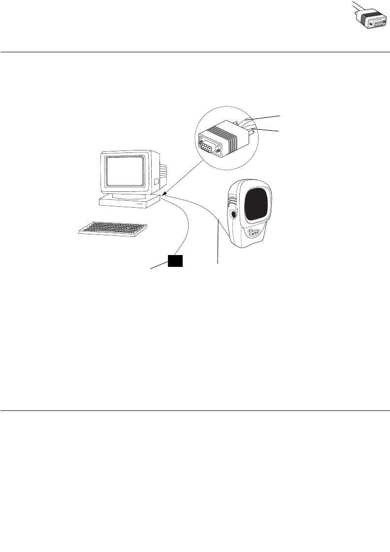
6-3
RS-232 Interface
Connecting an RS-232 Interface
This connection is made directly from the scanner to the host computer.
Figure 6-1. RS-232 Direct Connection
1. Connect the RS-232 interface cable to the rear of the scanner, as described in
Installing the Interface Cable on page 1-3.
2. Connect the other end of the interface cable to the serial port on the host.
3. Connect the power supply.
4. Scan appropriate bar codes in this chapter to match your host settings.
RS-232 Default Parameters
Table 6-1 lists the defaults for RS-232 host parameters. If you wish to change any option,
scan the appropriate bar code(s) provided in the Parameter Descriptions section beginning
on page 6-5.
Serial Port Connector to Host
Interface cable
Power supply
Interface cable
Power supply cable
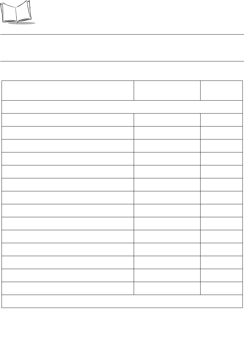
6-4
Symbol LS9208 Product Reference Guide
Note:See Appendix A, Standard Default Parameters for all user
preferences, hosts, symbologies, and miscellaneous default
parameters.
Table 6-1. RS-232 Host Default Table
Parameter Default Page
Number
RS-232 Host Parameters
RS-232 Host Types Standard16-7
Baud Rate 9600 6-10
Parity None 6-12
Check Receive Errors Enable 6-14
Hardware Handshaking None 6-15
Software Handshaking None 6-18
Host Serial Response Time-out 2 Sec 6-21
RTS Line State Low RTS 6-23
Stop Bit Select 1 6-24
Data Bits 8-Bit 6-25
Beep on <BEL> Disable 6-26
Intercharacter Delay 0 msec 6-27
Nixdorf Beep/LED Option Normal Operation 6-29
Ignore Unknown Characters Send Bar Codes 6-30
1User selection is required to configure this interface and this is the most common selection.
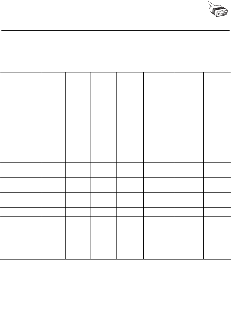
6-5
RS-232 Interface
RS-232 Host Parameters
Various RS-232 hosts are set up with their own parameter default settings (Table 6-2).
Selecting the ICL, Fujitsu, Wincor-Nixdorf Mode A, Wincor-Nixdorf Mode B, Olivetti, Omron,
or terminal sets the defaults listed below.
Table 6-2. Terminal Specific RS-232
Parameter Standard
(Default) ICL Fujitsu
Wincor-
Nixdorf
Mode A
Wincor-
Nixdorf
Mode B/
OPOS Olivetti Omron
Transmit Code ID No Yes Yes Yes Yes Yes Yes
Data
Transmission
Format
Data as is Data/
Suffix
Data/
Suffix
Data/Suffix Data/Suffix Prefix/Data/
Suffix
Data/Suffix
Suffix CR/LF
(7013)
CR (1013) CR (1013) CR (1013) CR (1013) ETX (1002) CR (1013)
Baud Rate 9600 9600 9600 9600 9600 9600 9600
Parity None Even None Odd Odd Even None
Hardware
Handshaking None RTS/CTS
Option 3
None RTS/CTS
Option 3
RTS/CTS
Option 3
None None
Software
Handshaking None None None None None Ack/Nak None
Serial Response
Time-out 2 Sec. 9.9 Sec. 2 Sec. 9.9 Sec. 9.9 Sec. 9.9 Sec. 9.9 Sec.
Stop Bit Select One One One One One One One
ASCII Format 8-Bit 8-Bit 8-Bit 8-Bit 8-Bit 7-Bit 8-Bit
Beep On <BEL> Disable Disable Disable Disable Disable Disable Disable
RTS Line State Low High Low Low Low = No
data to send
Low High
Prefix None None None None None STX (1003) None
*In the Nixdorf Mode B, if CTS is Low, scanning is disabled. When CTS is High, the user can scan
bar codes.
**If Nixdorf Mode B is scanned without the scanner connected to the proper host, it may appear
unable to scan. If this happens, scan a different RS-232 host type within 5 seconds of cycling power
to the scanner.
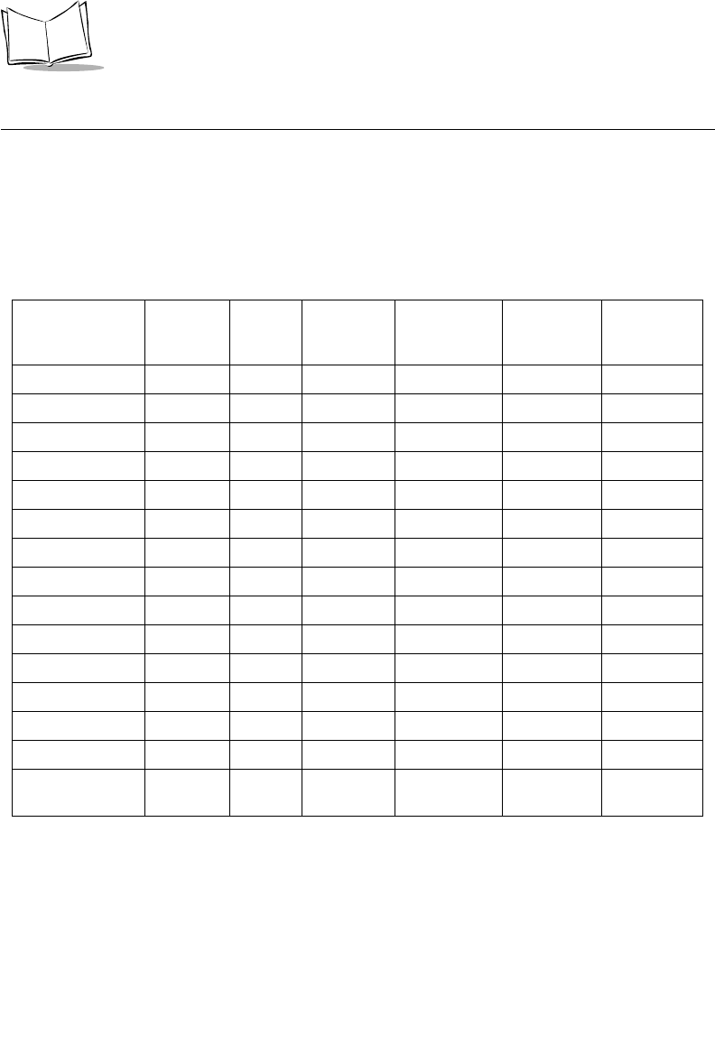
6-6
Symbol LS9208 Product Reference Guide
RS-232 Host Parameters (continued)
Selecting the ICL, Fujitsu, Wincor-Nixdorf Mode A, Wincor-Nixdorf Mode B, OPOS, JPOS
terminal enables the transmission of code ID characters listed in Table 6-3 below. These
code ID characters are not programmable and are separate from the Transmit Code ID
feature. The Transmit Code ID feature should not be enabled for these terminals.
Table 6-3. Terminal Specific Code ID Characters
ICL Fujitsu
Wincor-
Nixdorf
Mode A
Wincor-
Nixdorf
Mode B/OPOS Olivetti Omron
UPC-A AAA A A A
UPC-E EEC C C E
EAN-8/JAN-8 FF FF B B B FF
EAN-13/JAN-13 FFA A A F
Code 39 C <len> None M M M <len> C <len>
Codabar N <len> None N N N <len> N <len>
Code 128 L <len> None K K K <len> L <len>
I 2 of 5 I <len> None I I I <len> I <len>
Code 93 None None L L L <len> None
D 2 of 5 H <len> None H H H <len> H <len>
UCC/EAN 128 L <len> None P P P <len> L <len>
MSI None None O O O <len> None
Bookland EAN FFA A A F
IATA H<len> None H H None None
Unlisted Bar
Codes None None None None None None
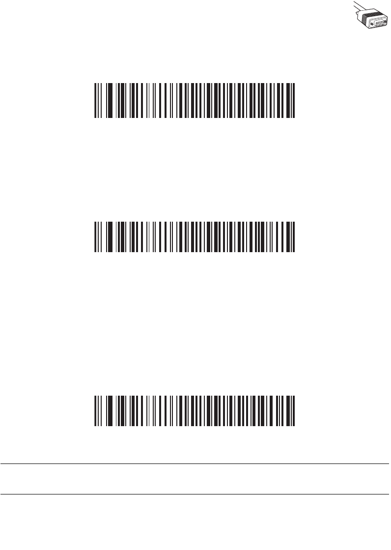
6-7
RS-232 Interface
RS-232 Host Types
To select an RS-232 host interface, scan one of the following bar codes.
Standard RS-2321
ICL RS-232
Wincor-Nixdorf RS-232 Mode A
Note:1User selection is required to configure this interface and this is the
most common selection.
6-8
Symbol LS9208 Product Reference Guide
RS-232 Host Types (continued)
Wincor-Nixdorf RS-232 Mode B
Fujitsu RS-232
Olivetti ORS4500
6-9
RS-232 Interface
RS-232 Host Types (continued)
Omron
OPOS/JPOS
Note:1User selection is required to configure this interface and this is the
most common selection.

6-10
Symbol LS9208 Product Reference Guide
Baud Rate
Baud rate is the number of bits of data transmitted per second. The scanner's baud rate
setting should match the baud rate setting of the host device. If not, data may not reach the
host device or may reach it in distorted form.
Baud Rate 600
Baud Rate 1200

6-11
RS-232 Interface
Baud Rate (continued)
Baud Rate 2400
Baud Rate 4800
*Baud Rate 9600
6-12
Symbol LS9208 Product Reference Guide
Baud Rate (continued)
Baud Rate 19,200
Baud Rate 38,400
Parity
A parity check bit is the most significant bit of each ASCII coded character. Select the parity
type according to host device requirements.
Select Odd parity and the parity bit value is set to 0 or 1, based on data, to ensure that an
odd number of 1 bits are contained in the coded character.
Odd

6-13
RS-232 Interface
Parity (continued)
Select Even parity and the parity bit value is set to 0 or 1, based on data, to ensure that an
even number of 1 bits are contained in the coded character.
Even
Select Mark parity and the parity bit is always 1.
Mark
Select Space parity and the parity bit is always 0.
Space
6-14
Symbol LS9208 Product Reference Guide
Parity (continued)
Select None when no parity bit is required.
*None
Check Receive Errors
Select whether or not the parity, framing, and overrun of received characters are checked.
The parity value of received characters is verified against the parity parameter selected
above.
*Check For Received Errors
Do Not Check For Received Errors

6-15
RS-232 Interface
Hardware Handshaking
The data interface consists of an RS-232 port designed to operate either with or without the
hardware handshaking lines, Request to Send (RTS), and Clear to Send (CTS).
If Standard RTS/CTS handshaking is not selected, scan data is transmitted as it becomes
available. If Standard RTS/CTS handshaking is selected, scan data is transmitted
according to the following sequence:
• The scanner reads the CTS line for activity. If CTS is asserted, the scanner waits
up to 2 seconds for the host to negate the CTS line. If, after 2 seconds (default),
the CTS line is still asserted, the scanner sounds a transmit error, and any scanned
data is lost.
• When the CTS line is negated, the scanner asserts the RTS line and waits up to 2
seconds for the host to assert CTS. When the host asserts CTS, data is
transmitted. If, after 2 seconds (default), the CTS line is not asserted, the scanner
sounds a transmit error, and discards the data.
• When data transmission is complete, the scanner negates RTS 10 msec after
sending the last character.
• The host should respond by negating CTS. The scanner checks for a negated CTS
upon the next transmission of data.
During the transmission of data, the CTS line should be asserted. If CTS is deasserted for
more than 50 ms between characters, the transmission is aborted, the scanner sounds a
transmission error, and the data is discarded.
If the above communications sequence fails, the scanner issues an error indication. In this
case, the data is lost and must be rescanned.
If Hardware Handshaking and Software Handshaking are both enabled, Hardware
Handshaking takes precedence.
Note:The DTR signal is jumpered to the active state.

6-16
Symbol LS9208 Product Reference Guide
None
Scan the bar code below if no Hardware Handshaking is desired.
*None
Standard RTS/CTS
Scan the bar code below to select Standard RTS/CTS Hardware Handshaking.
Standard RTS/CTS

6-17
RS-232 Interface
RTS/CTS Option 1
When RTS/CTS Option 1 is selected, the scanner asserts RTS before transmitting and
ignores the state of CTS. The scanner de-asserts RTS when the transmission is complete.
RTS/CTS Option 1
RTS/CTS Option 2
When Option 2 is selected, RTS is always high or low (user-programmed logic level).
However, the scanner waits for CTS to be asserted before transmitting data. If CTS is not
asserted within 2 seconds (default), the scanner issues an error indication and discards the
data.
RTS/CTS Option 2

6-18
Symbol LS9208 Product Reference Guide
RTS/CTS Option 3
When Option 3 is selected, the scanner asserts RTS prior to any data transmission,
regardless of the state of CTS. The scanner waits up to 2 seconds (default) for CTS to be
asserted. If CTS is not asserted during this time, the scanner issues an error indication and
discards the data. The scanner de-asserts RTS when transmission is complete.
RTS/CTS Option 3
Software Handshaking
This parameter offers control of the data transmission process in addition to, or instead of,
that offered by hardware handshaking. There are five options.
If Software Handshaking and Hardware Handshaking are both enabled, Hardware
Handshaking takes precedence.
None
When this option is selected, data is transmitted immediately.
*None

6-19
RS-232 Interface
ACK/NAK
When this option is selected, after transmitting data, the scanner expects either an ACK or
NAK response from the host. When a NAK is received, the scanner transmits the same data
again and waits for either an ACK or NAK. After three unsuccessful attempts to send data
when NAKs are received, the scanner issues an error indication and discards the data.
The scanner waits up to the programmable Host Serial Response Time-out to receive an
ACK or NAK. If the scanner does not get a response in this time, it issues an error indication
and discards the data. There are no retries when a time-out occurs.
ACK/NAK
ENQ
When this option is selected, the scanner waits for an ENQ character from the host before
transmitting data. If an ENQ is not received within the Host Serial Response Time-out, the
scanner issues an error indication and discards the data. The host must transmit an ENQ
character at least every Host Serial Response Time-out to prevent transmission errors.
ENQ
6-20
Symbol LS9208 Product Reference Guide
ACK/NAK with ENQ
This combines the two previous options.
ACK/NAK with ENQ
XON/XOFF
An XOFF character turns the scanner transmission off until the scanner receives an XON
character. There are two situations for XON/XOFF:
• XOFF is received before the scanner has data to send. When the scanner has data
to send, it waits up to 2 seconds for an XON character before transmission. If the
XON is not received within this time, the scanner issues an error indication and
discards the data.
• XOFF is received during a transmission. Data transmission then stops after
sending the current byte. When the scanner receives an XON character, it sends
the rest of the data message. The scanner waits indefinitely for the XON.
XON/XOFF

6-21
RS-232 Interface
Host Serial Response Time-out
This parameter specifies how long the scanner waits for an ACK, NAK, or CTS before
determining that a transmission error has occurred. This only applies when in one of the
ACK/NAK Software Handshaking modes, or RTS/CTS Hardware Handshaking option.
*Minimum: 2 Sec
Low: 2.5 Sec
Medium: 5 Sec

6-22
Symbol LS9208 Product Reference Guide
Host Serial Response Time-out (Continued)
High: 7.5 Sec
Maximum: 9.9 Sec

6-23
RS-232 Interface
RTS Line State
This parameter sets the idle state of the Serial Host RTS line. Scan a bar code below to
select Low RTS or High RTS line state.
*Host: Low RTS
Host: High RTS

6-24
Symbol LS9208 Product Reference Guide
Stop Bit Select
The stop bit(s) at the end of each transmitted character marks the end of transmission of
one character and prepares the receiving device for the next character in the serial data
stream. The number of stop bits selected (one or two) depends on the number the receiving
terminal is programmed to accommodate. Set the number of stop bits to match host device
requirements.
*1 Stop Bit
2 Stop Bits

6-25
RS-232 Interface
Data Bits
This parameter allows the scanner to interface with devices requiring a 7-bit or 8-bit ASCII
protocol.
7-Bit
*8-Bit

6-26
Symbol LS9208 Product Reference Guide
Beep on <BEL>
When this parameter is enabled, the scanner issues a beep when a <BEL> character is
detected on the RS-232 serial line. <BEL> is issued to gain a user's attention to an illegal
entry or other important event.
Beep On <BEL> Character
(Enable)
*Do Not Beep On <BEL> Character
(Disable)

6-27
RS-232 Interface
Intercharacter Delay
This parameter specifies the intercharacter delay inserted between character
transmissions.
*Minimum: 0 msec
Low: 25 msec
Medium: 50 msec

6-28
Symbol LS9208 Product Reference Guide
Intercharacter Delay (Continued)
High: 75 msec
Maximum: 99 msec

6-29
RS-232 Interface
Nixdorf Beep/LED Options
When Nixdorf Mode B is selected, this indicates when the scanner should beep and turn
on its LED after a decode.
*Normal Operation
(Beep/LED immediately after decode)
Beep/LED After Transmission
Beep/LED After CTS Pulse
6-30
Symbol LS9208 Product Reference Guide
Ignore Unknown Characters
Unknown characters are characters the host does not recognize. When Send Bar Codes
With Unknown Characters is selected, all bar code data is send except for unknown
characters, and no error beeps sound on the scanner. When Do Not Send Bar Codes With
Unknown Characters is selected, bar code data is sent up to the first unknown character
and then an error beep will sound on the scanner.
*Send Bar Code
(With Unknown Characters)
Do Not Send Bar Codes
(With Unknown Characters)
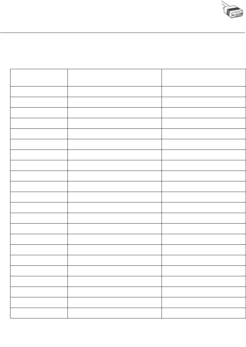
6-31
RS-232 Interface
ASCII / Character Set
The values in Table 6-4 can be assigned as prefixes or suffixes for ASCII character data
transmission.
Table 6-4. ASCII Character Set
ASCII Value Full ASCII
Code 39 Encode Character ASCII Character
1000 %U NUL
1001 $A SOH
1002 $B STX
1003 $C ETX
1004 $D EOT
1005 $E ENQ
1006 $F ACK
1007 $G BELL
1008 $H BCKSPC
1009 $I HORIZ TAB
1010 $J LF/NW LN
1011 $K VT
1012 $L FF
1013 $M CR/ENTER
1014 $N SO
1015 $O SI
1016 $P DLE
1017 $Q DC1
1018 $R DC2
1019 $S DC3
1020 $T DC4
1021 $U NAK

6-32
Symbol LS9208 Product Reference Guide
1022 $V SYN
1023 $W ETB
1024 $X CAN
1025 $Y EM
1026 $Z SUB
1027 %A ESC
1028 %B FS
1029 %C GS
1030 %D RS
1031 %E US
1032 Space Space
1033 /A !
1034 /B "
1035 /C #
1036 /D $
1037 /E %
1038 /F &
1039 /G ‘
1040 /H (
1041 /I )
1042 /J *
1043 /K +
1044 /L ,
1045 - -
1046 . .
1047 /O /
Table 6-4. ASCII Character Set
ASCII Value Full ASCII
Code 39 Encode Character ASCII Character

6-33
RS-232 Interface
1048 0 0
1049 1 1
1050 2 2
1051 3 3
1052 4 4
1053 5 5
1054 6 6
1057 7 7
1056 8 8
1057 9 9
1058 /Z :
1059 %F ;
1060 %G <
1061 %H =
1062 %I >
1063 %J ?
1064 %V @
1065 A A
1066 B B
1067 C C
1068 D D
1069 E E
1070 F F
1071 G G
1072 H H
1073 I I
Table 6-4. ASCII Character Set
ASCII Value Full ASCII
Code 39 Encode Character ASCII Character

6-34
Symbol LS9208 Product Reference Guide
1074 J J
1075 K K
1076 L L
1077 M M
1078 N N
1079 O O
1080 P P
1081 Q Q
1082 R R
1083 S S
1084 T T
1085 U U
1086 V V
1087 W W
1088 X X
1089 Y Y
1090 Z Z
1091 %K [
1092 %L \
1093 %M ]
1094 %N ^
1095 %O _
1096 %W `
1097 +A a
1098 +B b
1099 +C c
Table 6-4. ASCII Character Set
ASCII Value Full ASCII
Code 39 Encode Character ASCII Character

6-35
RS-232 Interface
1100 +D d
1101 +E e
1102 +F f
1103 +G g
1104 +H h
1105 +I i
1106 +J j
1107 +K k
1108 +L l
1109 +M m
1110 +N n
1111 +O o
1112 +P p
1113 +Q q
1114 +R r
1115 +S s
1116 +T t
1117 +U u
1118 +V v
1119 +W w
1120 +X x
1121 +Y y
1122 +Z z
1123 %P {
1124 %Q |
1125 %R }
Table 6-4. ASCII Character Set
ASCII Value Full ASCII
Code 39 Encode Character ASCII Character

6-36
Symbol LS9208 Product Reference Guide
1126 %S ~
1127 Undefined
7013 ENTER
Table 6-4. ASCII Character Set
ASCII Value Full ASCII
Code 39 Encode Character ASCII Character
7-1
Chapter 7
USB Interface
Introduction
This chapter covers the connection and setup of the scanner to a USB host. The scanner
attaches directly to a USB host, or a powered USB hub, and is powered by it. No additional
power supply is required.
Throughout the programming bar code menus, default values are indicated with asterisks
(*).
Feature/Option
* Indicates Default
*North American, Standard USB Keyboard
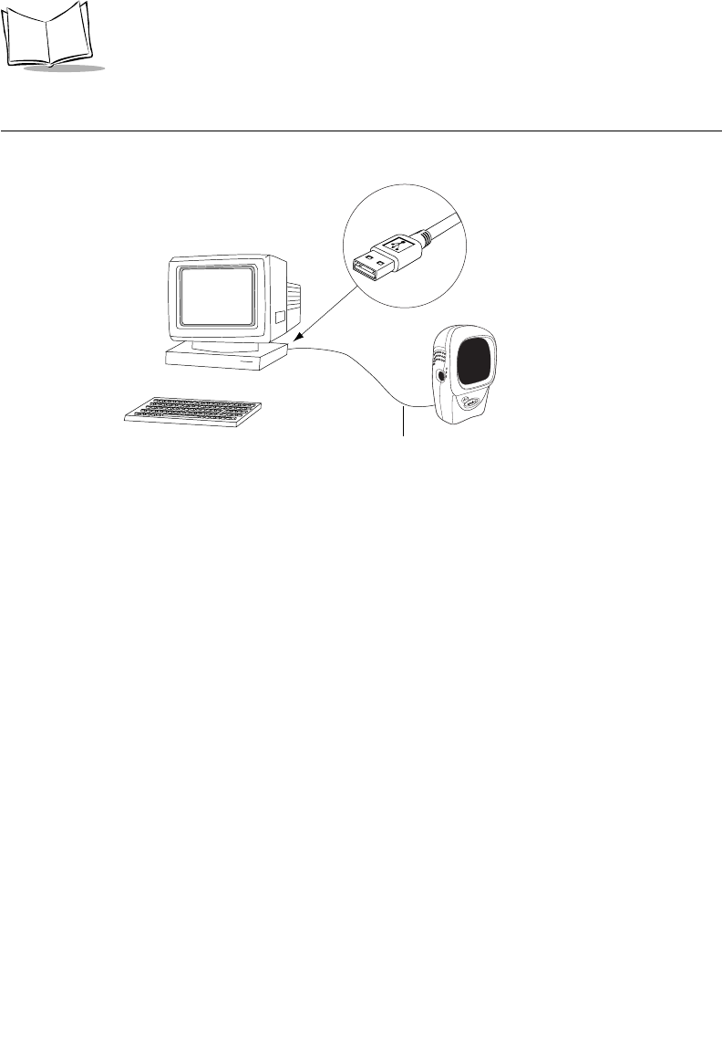
7-2
Symbol LS9208 Product Reference Guide
Connecting a USB Interface
Figure 7-1. USB Connection
The scanner connects with USB capable hosts including:
• Desktop PCs and Notebooks
• Apple™ iMac, G4, iBooks (North America only)
• IBM SurePOS terminals
• Sun, IBM, and other network computers that support more than one keyboard.
The following operating systems support the scanner through USB:
• Windows 98, 2000, ME, XP
• MacOS 8.5 and above
• IBM 4690 OS.
The scanner will also interface with other USB hosts which support USB Human Interface
Devices (HID). For more information on USB technology, hosts, and peripheral devices,
visit www.symbol.com/usb.
To set up your scanner:
1. Connect the USB interface cable to the rear of the scanner, as described in
Installing the Interface Cable on page 1-3.
USB Series A Connector
Interface cable

7-3
USB Interface
2. Plug the series A connector in the USB host or hub, or plug the Plus Power
connector in an available port of the IBM SurePOS terminal.
3. Select the USB device type. See USB Device Type on page 7-5.
4. On first installation when using Windows, the software prompts you to select or
install the "Human Interface Device" driver. To install the "Human Interface Device"
driver provided by Windows click "Next" through all the choices and click "Finished"
on the last choice. The scanner powers up during this installation.
5. If you are not using a North American keyboard, scan the appropriate country bar
code under USB Country Keyboard Types (Country Codes) on page 7-8.
If you are having any problems with your system, see Troubleshooting on page 3-2.
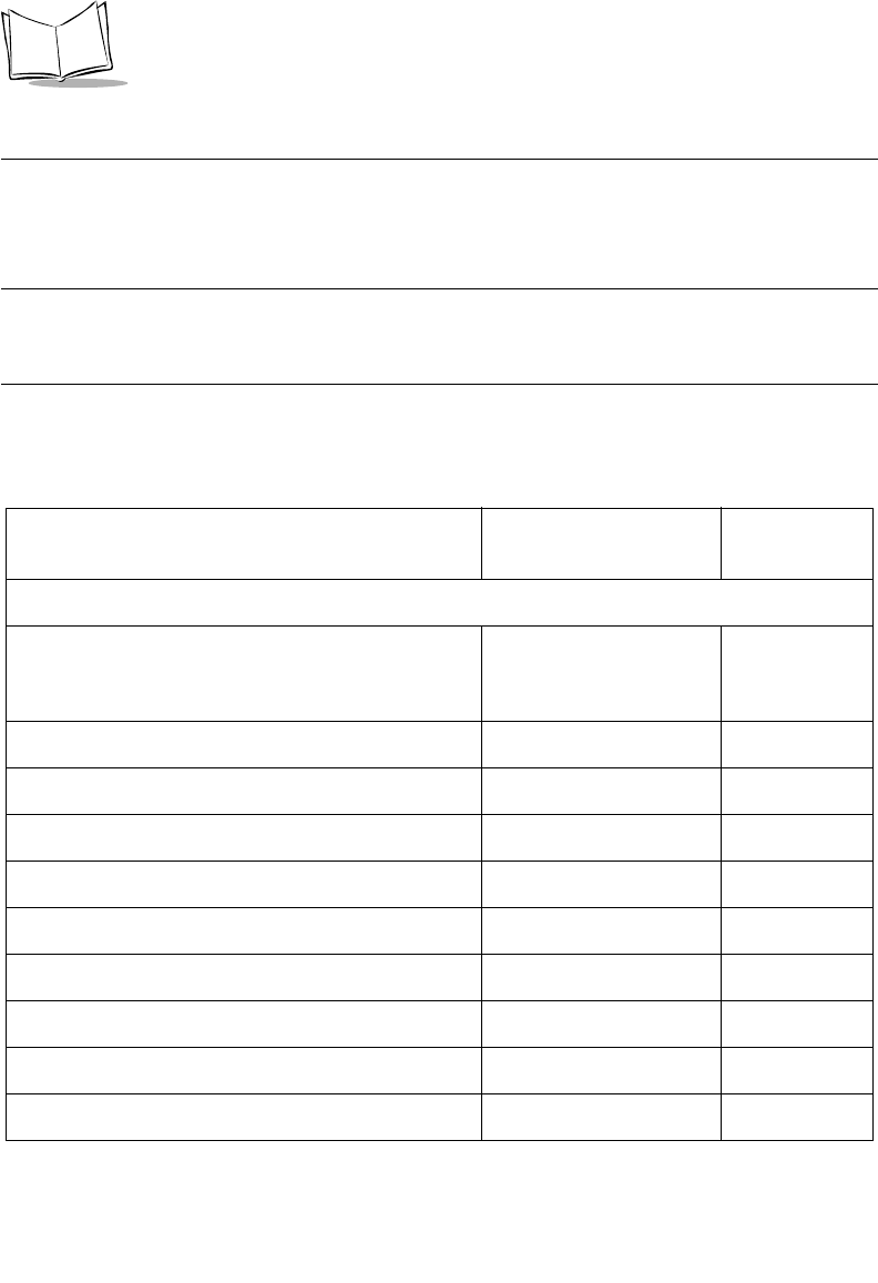
7-4
Symbol LS9208 Product Reference Guide
USB Default Parameters
Table 7-1 lists the defaults for USB host parameters. If you wish to change any option, scan
the appropriate bar code(s) provided in the Parameter Descriptions section beginning on
page 7-5.
Note:See Appendix A, Standard Default Parameters for all user
preferences, hosts, symbologies, and miscellaneous default
parameters.
Table 7-1. USB Host Default Table
Parameter Default Page
Number
USB Host Parameters
USB Device Type HID (Human Interface
Device) Keyboard
Emulation
7-5
USB Country Keyboard Types (Country Codes) North American 7-8
USB Keystroke Delay No Delay 7-12
USB CAPS Lock Override Disable 7-13
USB Ignore Unknown Characters Send Bar Codes 7-14
Emulate Keypad Disable 7-15
USB Keyboard FN1 Substitution Disable 7-16
Function Key Mapping Disable 7-17
Simulated Caps Lock Disable 7-18
Convert Case Disable 7-19

7-5
USB Interface
USB Host Parameters
USB Device Type
Select the desired USB device type.
•HID Keyboard Emulation (default) - This device type allows the scanner to
emulate a USB keyboard. When a bar code is successfully decoded, bar code data
is transmitted to the console as if the data was typed on a keyboard. No special
drivers are required as HID Keyboard Emulation is supported by most USB
drivers.
• IBM Table Top USB - This device type is used with table top scanners connecting
to a cash register with IBM OEM specification compliant drivers (supplied by the
cash register vendor). IBM Table Top USB requires drivers supplied by the Point-
of-Service (POS) device vendor. Check with the POS vendor to verify the drivers
used.
• IBM Hand-Held USB - This device type is used with hand-held scanners
connecting to a cash register with IBM OEM specification compliant drivers
(supplied by the cash register vendor). IBM Hand-Held USB requires drivers
supplied by the Point-of-Service (POS) device vendor. Check with the POS vendor
to verify the drivers used.
Note:When connecting two scanners to a host, IBM does not permit the
selection of two of the same device types. When two connections
are required, select IBM Table Top USB for one scanner and IBM
Hand-Held USB for the second scanner.
• USB OPOS Hand-Held - This device type is used with Symbol’s OPOS/JPOS
compliant drivers, which can be downloaded from Symbol’s Software Developer
Zone at http://devzone.symbol.com. Motorola only supports one OPOS connection
per host.
• Simple COM Port Emulation - This device type requires a Motorola driver
download from the Software Developer Zone at http://devzone.symbol.com. When
the scanner is connected to the host the next available comm port is automatically
selected, emulating a one-way RS-232 connection. No handshaking is supported.
No baud settings are required.
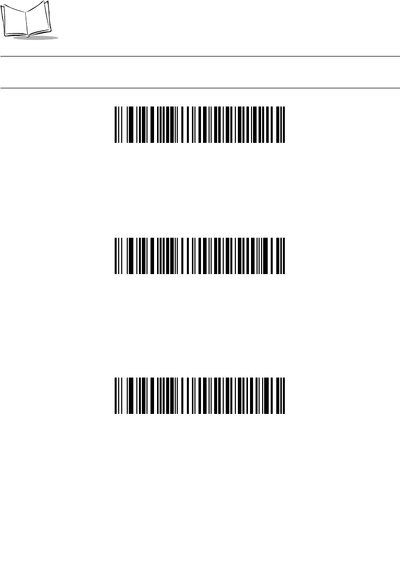
7-6
Symbol LS9208 Product Reference Guide
Note:When changing USB Device Types, the scanner automatically
restarts. The scanner issues the standard startup beep sequences.
IBM Table Top USB
*HID Keyboard Emulation
IBM Hand-Held USB

7-7
USB Interface
USB Device Type (Continued)
USB OPOS Hand-Held
Simple COM Port Emulation
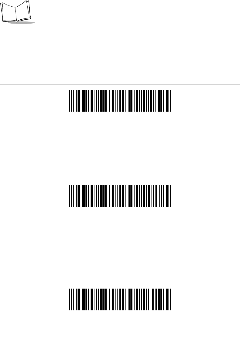
7-8
Symbol LS9208 Product Reference Guide
USB Country Keyboard Types (Country Codes)
Scan the bar code corresponding to your keyboard type. This setting applies only to the
USB HID Keyboard Emulation device.
Note:When changing Country Selection, the scanner automatically
restarts. The scanner issues the standard startup beep sequences.
*North American, Standard USB Keyboard
French, Windows
German, Windows

7-9
USB Interface
USB Country Keyboard Types (Continued)
Spanish (Traditional), Windows
French Canadian, Windows
French Canadian, Windows 2000/XP

7-10
Symbol LS9208 Product Reference Guide
USB Country Keyboard Types (Continued)
Swedish, Windows
UK English, Windows
Italian, Windows

7-11
USB Interface
USB Country Keyboard Types (Continued)
Portuguese-Brazilian, Windows
Japanese, Windows (ASCII)
7-12
Symbol LS9208 Product Reference Guide
USB Keystroke Delay
This parameter sets the delay, in milliseconds, between emulated keystrokes. Scan a bar
code below to increase the delay when hosts require a slower transmission of data.
*No Delay
Long Delay (40 msec)
Medium Delay (20 msec)

7-13
USB Interface
USB CAPS Lock Override
This option applies only to the HID Keyboard Emulation device. When enabled, the case of
the data is preserved regardless of the state of the caps lock key. This setting is always
enabled for the “Japanese, Windows (ASCII)” keyboard type and can not be disabled.
*Do Not Override Caps Lock Key
(Disable)
Override Caps Lock Key
(Enable)

7-14
Symbol LS9208 Product Reference Guide
USB Ignore Unknown Characters
This option applies only to the HID Keyboard Emulation device and IBM device. Unknown
characters are characters the host does not recognize. When Send Bar Codes With
Unknown Characters is selected, all bar code data is sent except for unknown characters,
and no error beeps sound. When Do Not Send Bar Codes With Unknown Characters is
selected, bar codes containing at least one unknown character are not sent to the host, and
an error beep sounds.
.
*Send Bar Codes With Unknown Characters
Do Not Send Bar Codes With Unknown
Characters

7-15
USB Interface
Emulate Keypad
When enabled, all characters are sent as ASCII sequences over the numeric keypad. For
example ASCII A would be sent as “ALT make” 0 6 5 “ALT Break”.
*Disable Keypad Emulation
Enable Keypad Emulation

7-16
Symbol LS9208 Product Reference Guide
USB Keyboard FN1 Substitution
This option applies only to the USB HID Keyboard Emulation device. When enabled, this
allows replacement of any FN1 characters in an EAN 128 bar code with a Key Category
and value chosen by the user (see FN1 Substitution Values on page 12-8 to set the Key
Category and Key Value).
Enable
*Disable

7-17
USB Interface
Function Key Mapping
ASCII values under 32 are normally sent as a control-key sequences (see Table 7-2 on
page 7-20). When this parameter is enabled, the keys in bold are sent in place of the
standard key mapping. Table entries that do not have a bold entry remain the same whether
or not this parameter is enabled.
*Disable Function Key Mapping
Enable Function Key Mapping
7-18
Symbol LS9208 Product Reference Guide
Simulated Caps Lock
*Disable Simulated Caps Lock
Enable Simulated Caps Lock

7-19
USB Interface
Convert Case
When enabled, the scanner will convert all bar code data to the selected case.
*No Case Conversion
Convert All to Upper Case
Convert All to Lower Case
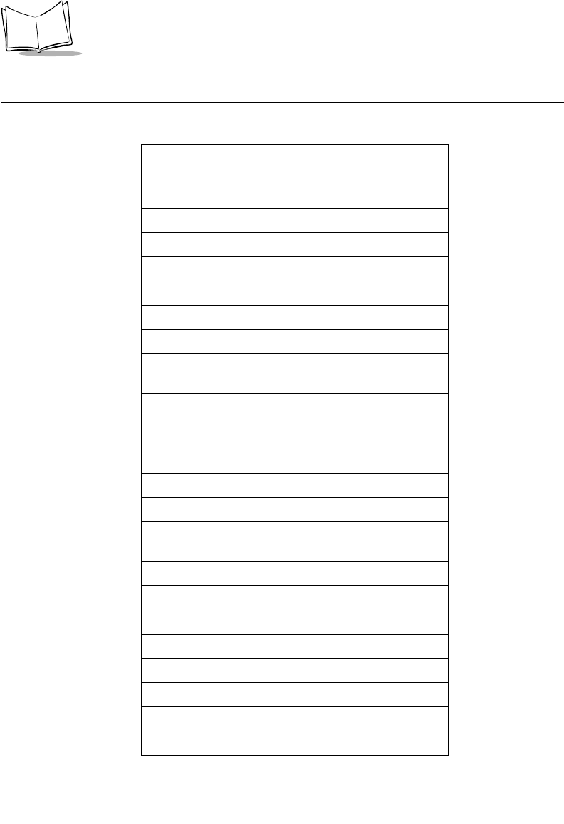
7-20
Symbol LS9208 Product Reference Guide
ASCII Character Set
Table 7-2. USB ASCII Character Set
ASCII Value Full ASCII Code
39 Encode Char. Keystroke
1001 $A CTRL A
1002 $B CTRL B
1003 $C CTRL C
1004 $D CTRL D
1005 $E CTRL E
1006 $F CTRL F
1007 $G CTRL G
1008 $H CTRL H/
BACKSPACEa
1009 $I CTRL I/
HORIZONTAL
TABa
1010 $J CTRL J
1011 $K CTRL K
1012 $L CTRL L
1013 $M CTRL M/
ENTERa
1014 $N CTRL N
1015 $O CTRL O
1016 $P CTRL P
1017 $Q CTRL Q
1018 $R CTRL R
1019 $S CTRL S
1020 $T CTRL T
1021 $U CTRL U
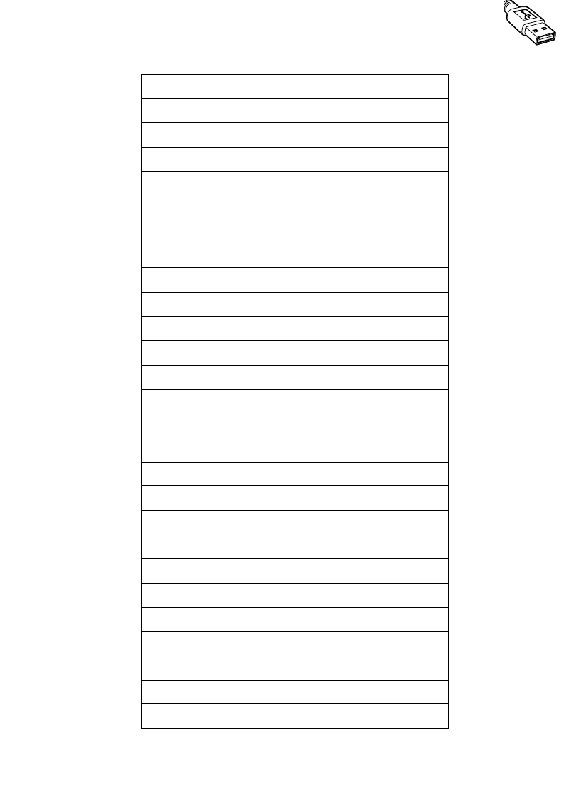
7-21
USB Interface
1022 $V CTRL V
1023 $W CTRL W
1024 $X CTRL X
1025 $Y CTRL Y
1026 $Z CTRL Z
1027 %A NONE/ESCa
1028 %B NONE
1029 %C NONE
1030 %D NONE
1031 %E NONE
1032 Space Space
1033 /A !
1034 /B “
1035 /C #
1036 /D $
1037 /E %
1038 /F &
1039 /G ‘
1040 /H (
1041 /I )
1042 /J *
1043 /K +
1044 /L ,
1045 - -
1046 . .
1047 /O /
1048 0 0
Table 7-2. USB ASCII Character Set (Continued)

7-22
Symbol LS9208 Product Reference Guide
1049 1 1
1050 2 2
1051 3 3
1052 4 4
1053 5 5
1054 6 6
1055 7 7
1056 8 8
1057 9 9
1058 /Z :
1059 %F ;
1060 %G <
1061 %H =
1062 %I >
1063 %J ?
1064 %V @
1065 A A
1066 B B
1067 C C
1068 D D
1069 E E
1070 F F
1071 G G
1072 H H
1073 I I
1074 J J
1075 K K
Table 7-2. USB ASCII Character Set (Continued)

7-23
USB Interface
1076 L L
1077 M M
1078 N N
1079 O O
1080 P P
1081 Q Q
1082 R R
1083 S S
1084 T T
1085 U U
1086 V V
1087 W W
1088 X X
1089 Y Y
1090 Z Z
1091 %K [
1092 %L \
1093 %M ]
1094 %N ^
1095 %O _
1096 %W `
1097 +A a
1098 +B b
1099 +C c
1100 +D d
1101 +E e
1102 +F f
Table 7-2. USB ASCII Character Set (Continued)
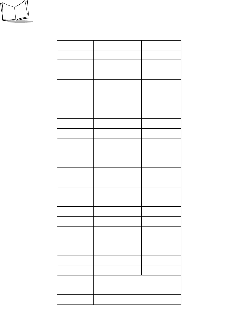
7-24
Symbol LS9208 Product Reference Guide
1103 +G g
1104 +H h
1105 +I i
1106 +J j
1107 +K k
1108 +L l
1109 +M m
1110 +N n
1111 +O o
1112 +P p
1113 +Q q
1114 +R r
1115 +S s
1116 +T t
1117 +U u
1118 +V v
1119 +W w
1120 +X x
1121 +Y y
1122 +Z z
1123 %P {
1124 %Q |
1125 %R }
1126 %S ~
ALT Keys Keystroke
2065 ALT A
2066 ALT B
Table 7-2. USB ASCII Character Set (Continued)

7-25
USB Interface
2067 ALT C
2068 ALT D
2069 ALT E
2070 ALT F
2071 ALT G
2072 ALT H
2073 ALT I
2074 ALT J
2075 ALT K
2076 ALT L
2077 ALT M
2078 ALT N
2079 ALT O
2080 ALT P
2081 ALT Q
2082 ALT R
2083 ALT S
2084 ALT T
2085 ALT U
2086 ALT V
2087 ALT W
2088 ALT X
2089 ALT Y
2090 ALT Z
Table 7-2. USB ASCII Character Set (Continued)
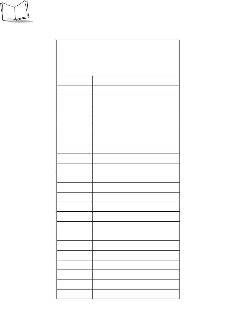
7-26
Symbol LS9208 Product Reference Guide
GUI Shift Keys
The Apple™ iMac keyboard has an apple key on either side
of the space bar. Windows-based systems have a GUI key
to the left of the left ALT key, and to the right of the right ALT
key.
Other Value Keystroke
3000 Right Control Key
3048 GUI 0
3049 GUI 1
3050 GUI 2
3051 GUI 3
3052 GUI 4
3053 GUI 5
3054 GUI 6
3055 GUI 7
3056 GUI 8
3057 GUI 9
3065 GUI A
3066 GUI B
3067 GUI C
3068 GUI D
3069 GUI E
3070 GUI F
3071 GUI G
3072 GUI H
3073 GUI I
3074 GUI J
3075 GUI K
Table 7-2. USB ASCII Character Set (Continued)

7-27
USB Interface
3076 GUI L
3077 GUI M
3078 GUI N
3079 GUI O
3080 GUI P
3081 GUI Q
3082 GUI R
3083 GUI S
3084 GUI T
3085 GUI U
3086 GUI V
3087 GUI W
3088 GUI X
3089 GUI Y
3090 GUI Z
F Keys Keystroke
5001 F1
5002 F2
5003 F3
5004 F4
5005 F5
5006 F6
5007 F7
5008 F8
5009 F9
5010 F10
5011 F11
Table 7-2. USB ASCII Character Set (Continued)
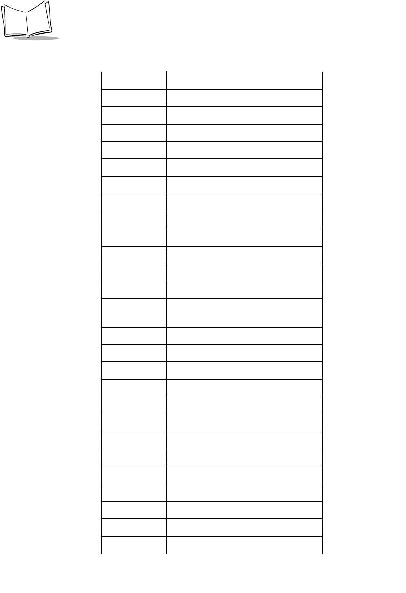
7-28
Symbol LS9208 Product Reference Guide
5012 F12
5013 F13
5014 F14
5015 F15
5016 F16
5017 F17
5018 F18
5019 F19
5020 F20
5021 F21
5022 F22
5023 F23
5024 F24
Numeric
Keypad Keystroke
6042 *
6043 +
6045 -
6046 .
6047 /
6048 0
6049 1
6050 2
6051 3
6052 4
6053 5
6054 6
6055 7
Table 7-2. USB ASCII Character Set (Continued)
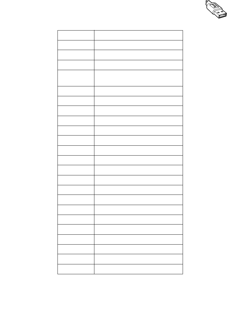
7-29
USB Interface
6056 8
6057 9
6058 Enter
6059 Num Lock
Extended
Keypad Keystroke
7001 Break
7002 Delete
7003 PgUp
7004 End
7005 Pg Dn
7006 Pause
7007 Scroll Lock
7008 Backspace
7009 Tab
7010 Print Screen
7011 Insert
7012 Home
7013 Enter
7014 Escape
7015 Up Arrow
7016 Down Arrow
7017 Left Arrow
7018 Right Arrow
a. The Keystroke in bold is sent only if the
“Function Key Mapping” parameter is en-
abled. Otherwise, the unbolded keystroke is
sent.
Table 7-2. USB ASCII Character Set (Continued)

7-30
Symbol LS9208 Product Reference Guide
8-1
Chapter 8
IBM 468X/469X Interface
Introduction
This chapter covers IBM 468X/469X host information for setting up your scanner.
Throughout the programming bar code menus, default values are indicated with asterisks
(*).
*Disable Convert
Unknown to Code 39
Feature/Option
* Indicates Default
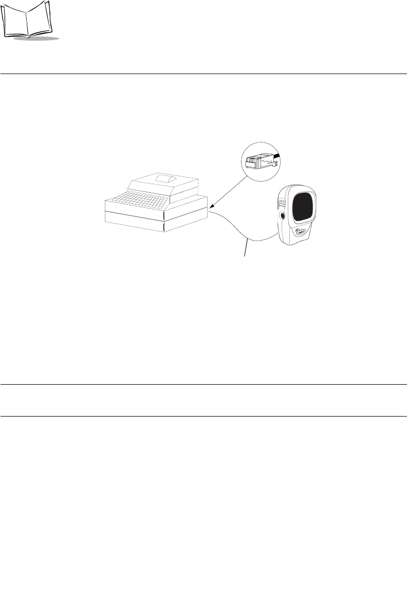
8-2
Symbol LS9208 Product Reference Guide
Connecting to an IBM 468X/469X Host
This connection is made directly from the scanner to the host interface.
Figure 8-1. IBM Direct Connection
1. Connect the interface cable to the rear of the scanner, as described in Installing the
Interface Cable on page 1-3.
2. Connect the other end of the interface cable to the appropriate port on the host
(typically, Port 9).
3. Scan the appropriate bar codes in this chapter to configure the scanner.
Note:The only required configuration is the port number. Most other
scanner parameters are typically controlled by the IBM system.
Host Port Connector
Interface cable
8-3
IBM 468X/469X Interface
IBM Default Parameters
Table 8-1 lists the defaults for IBM host parameters. If you wish to change any option, scan
the appropriate bar code(s) provided in the Parameter Descriptions section beginning on
page 8-4.
Note:See Appendix A, Standard Default Parameters for all user
preferences, hosts, symbologies, and miscellaneous default
parameters.
Table 8-1. IBM Host Default Table
Parameter Default Page
Number
IBM 468X/469X Host Parameters
Port Address None Selected18-4
Convert Unknown to Code 39 Disable 8-6
1User selection is required to configure this interface and this is the most common selection.
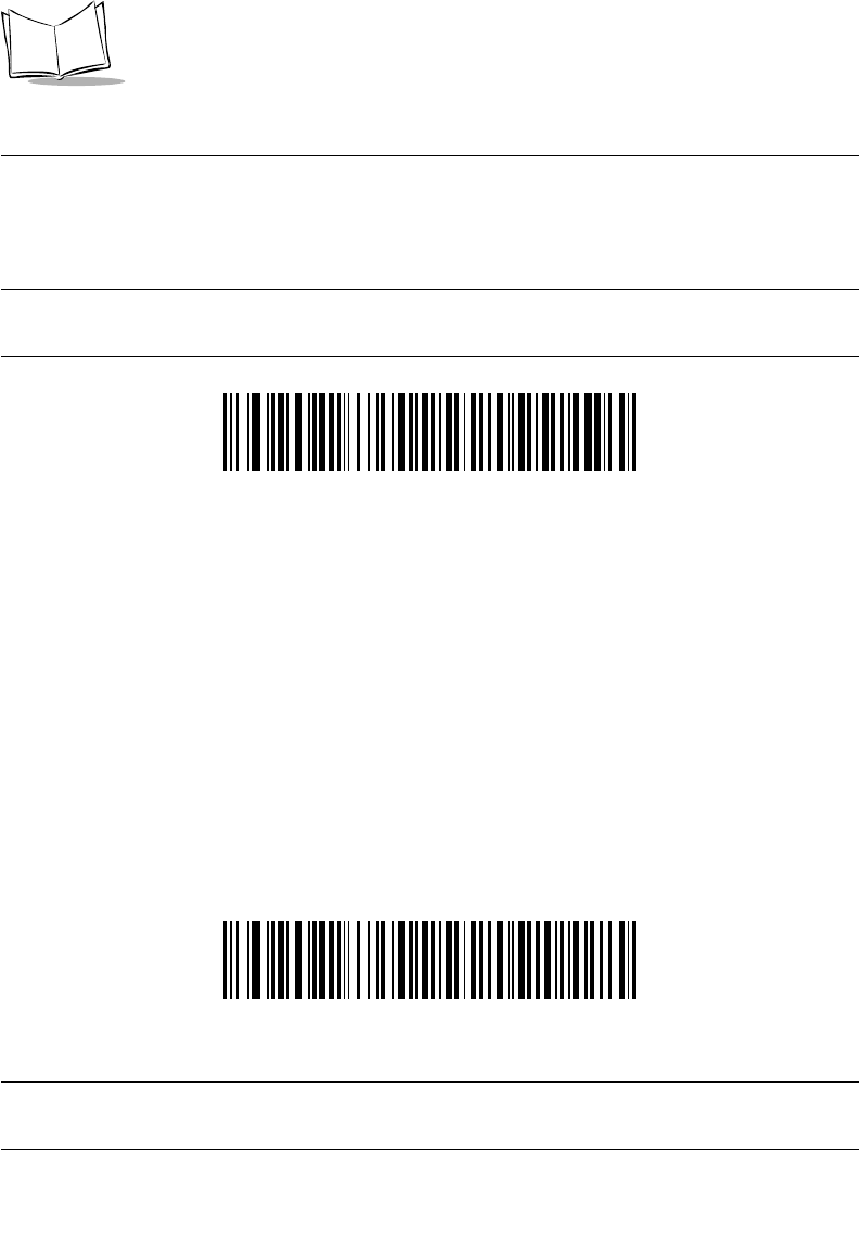
8-4
Symbol LS9208 Product Reference Guide
IBM 468X/469X Host Parameters
Port Address
This parameter sets the IBM 468X/469X port being used.
Note:Scanning one of these bar codes enables the RS-485 interface on
the scanner.
Note:1User selection is required to configure this interface and this is the
most common selection.
Hand-held Scanner Emulation (Port 9B)1
* None Selected

8-5
IBM 468X/469X Interface
Port Address (Continued)
Table-top Scanner Emulation (Port 17)
Non-IBM Scanner Emulation (Port 5B)
8-6
Symbol LS9208 Product Reference Guide
Convert Unknown to Code 39
Scan a bar code below to enable or disable the conversion of unknown bar code type data
to Code 39.
Enable Convert to Code 39
Enable Convert Unknown to Code 39
*Disable Convert Unknown to Code 39

9-1
Chapter 9
Wand Emulation Interface
Introduction
This chapter covers Wand Emulation host information for setting up your scanner. This
mode is used whenever Wand Emulation communication is needed. The scanner will
attach either to an external wand decoder or to a decoder integrated in a portable terminal
or Point-of-Sale (POS) terminal.
In this mode the scanner emulates the signal of a digital wand to make it "readable" by a
wand decoder.
Throughout the programming bar code menus, default values are indicated with asterisks
(*).
*Transmit Unknown
Characters Feature/Option
* Indicates Default
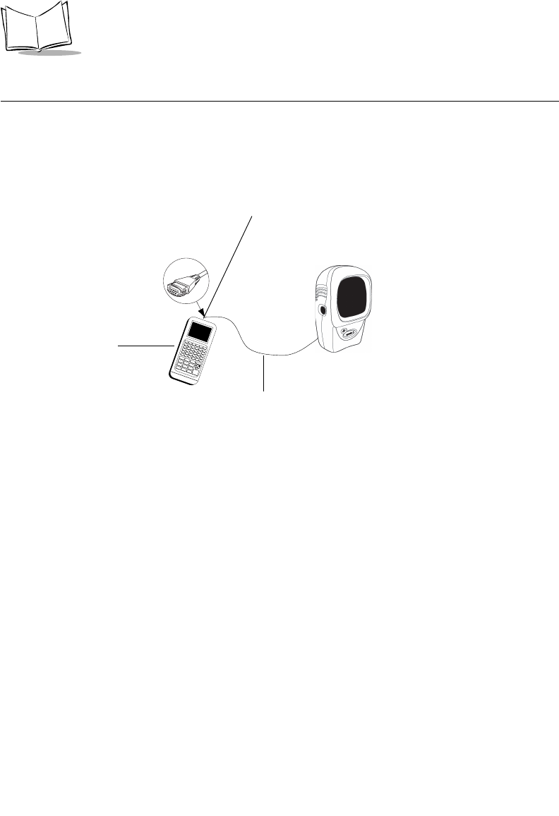
9-2
Symbol LS9208 Product Reference Guide
Connecting Using Wand Emulation
To perform Wand Emulation, connect the scanner to a portable data terminal, or a controller
which collects the wand data and interprets it for the host.
Figure 9-1. Wand Emulation Connection
1. Connect the Wand Emulation interface cable to the rear of the scanner, as
described in Installing the Interface Cable on page 1-3.
2. Connect the other end of the interface cable to the Wand port on the portable data
terminal or controller.
3. Scan the appropriate bar codes in this chapter to configure the scanner.
Interface cable
Wand port
Portable data
Terminal
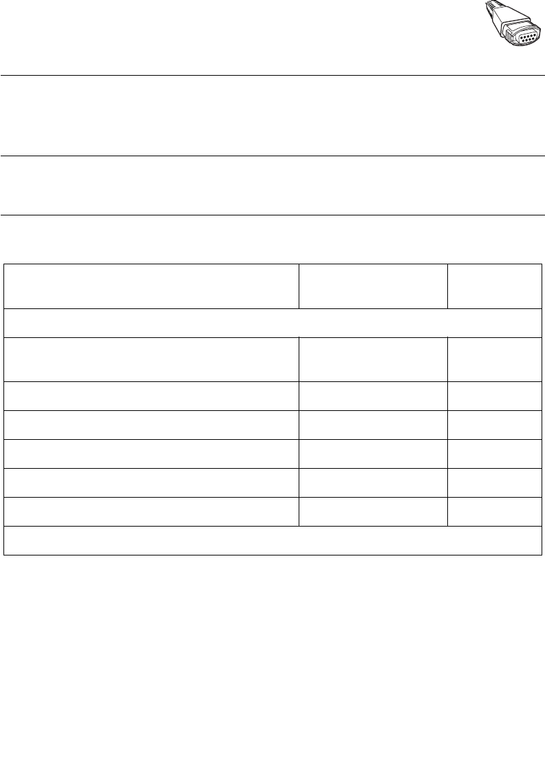
9-3
Wand Emulation Interface
Wand Emulation Default Parameters
Table 9-1 lists the defaults for Wand Emulation host types. If you wish to change any option,
scan the appropriate bar code(s) provided in the Wand Emulation Host Parameters section
beginning on page 9-4.
Note:See Appendix A, Standard Default Parameters for all user
preferences, hosts, symbologies, and miscellaneous default
parameters.
Table 9-1. Wand Emulation Default Table
Parameter Default Page
Number
Wand Emulation Host Parameters
Wand Emulation Host Types Symbol OmniLink
Interface Controller19-4
Leading Margin 80 msec 9-5
Polarity Bar High/Margin Low 9-6
Ignore Unknown Characters Send Bar Codes 9-7
Convert All Bar Codes to Code 39 Disable 9-8
Convert Code 39 to Full ASCII Disable 9-9
1User selection is required to configure this interface and this is the most common selection.
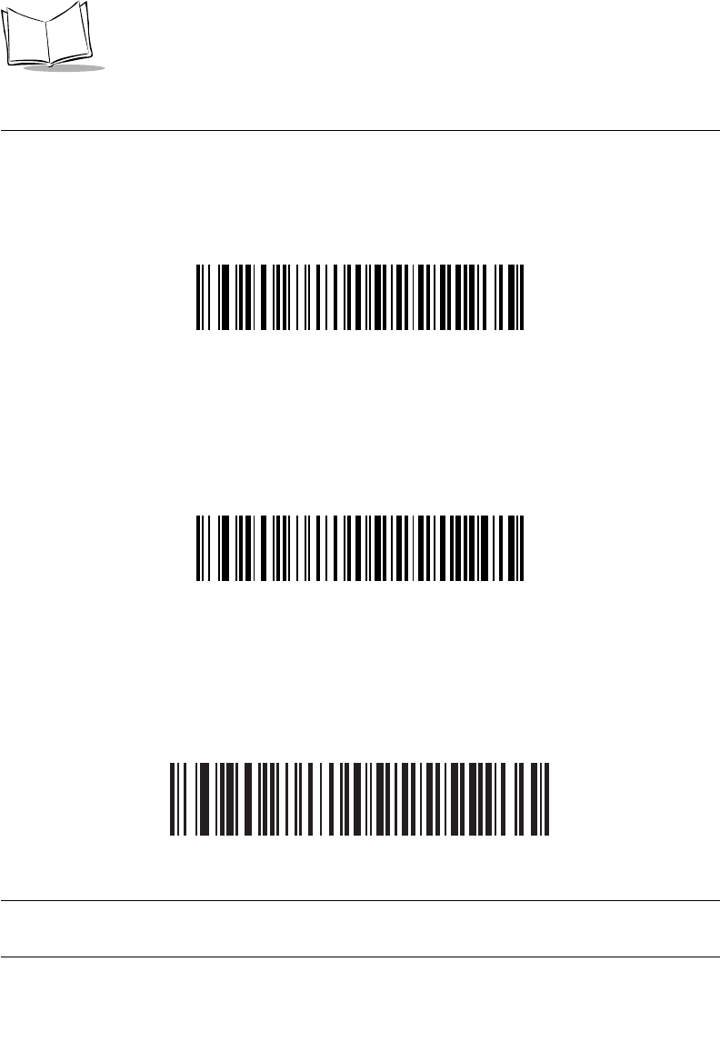
9-4
Symbol LS9208 Product Reference Guide
Wand Emulation Host Parameters
Wand Emulation Host Types
Select your wand emulation host by scanning one of the bar codes below.
Symbol OmniLink Interface Controller1
Symbol PDT Terminal (MSI)
Symbol PTC Terminal (Telxon)
Note:1User selection is required to configure this interface and this is the
most common selection.
9-5
Wand Emulation Interface
Leading Margin (Quiet Zone)
Scan a bar code below to select a leading margin duration. A leading margin is the time that
precedes the first bar of the scan, (in milliseconds). The minimum allowed value is 80 msec
and the maximum is 250 msec. This parameter is used to accommodate older wand
decoders which cannot handle short leading margins.
Note:250 msec is the maximum value that this parameter can attain,
however, 200 msec is sufficient.
*80 msec
140 msec
200 msec

9-6
Symbol LS9208 Product Reference Guide
Polarity
Polarity determines how the scanner's wand emulation interface creates the Digitized
Barcode Pattern (DBP). DBP is a digital signal that represents the scanned bar code.
Different decoders, to which this device could be attached, are expecting the DBP to be in
a certain format. The DBP either has the "highs" represent bars and the "lows" represent
spaces (margins), or the "highs" represent spaces (margins) and the "lows" represent bars.
Scan the appropriate bar code below to select the polarity required by your decoder.
*Bar High/Margin Low
Bar Low/Margin High

9-7
Wand Emulation Interface
Ignore Unknown Characters
Unknown characters are characters the host does not recognize. When Send Bar Codes
With Unknown Characters is selected, all bar code data is sent except for unknown
characters, and no error beeps sound on the scanner. When Do Not Send Bar Codes With
Unknown Characters is selected, bar codes containing at least one unknown character
are not sent to the host, and then an error beep will sound on the scanner.
*Send Bar Codes With Unknown Characters
Do Not Send Bar Codes With Unknown Characters

9-8
Symbol LS9208 Product Reference Guide
Convert All Bar Codes to Code 39
By default, the Wand Emulation Interface sends data to the attached host in the same
symbology that was decoded. This may present a problem for customers with legacy
systems that do not recognize some newer symbologies (for example, RSS).
Enabling this parameter ignores the original symbology that was decoded, and outputs the
data as if it were a Code 39 barcode. Any lowercase characters that were in the original
data stream are transmitted as uppercase characters. This also allows ADF Formatting to
occur.
If Ignore Unknown Characters is enabled, any characters that do not have a corresponding
character in the Code 39 symbology set are replaced by a space.
If Ignore Unknown Characters is disabled, if any characters that do not have a
corresponding character are encountered, the scanner emits an error beep and no data is
transmitted.
ADF Note: By default, the Wand Emulation Interface does not allow scanned data to be
processed by ADF rules. Enabling this parameter has the side effect of allowing the
scanned data to be processed by the ADF rules (See Chapter 13).
Enable Convert to Code 39 for Wand Host
*Disable Convert to Code 39 for Wand Host

9-9
Wand Emulation Interface
Convert Code 39 to Full ASCII
By default, any characters that do not have a corresponding character in the Code 39
symbology set are replaced by a space. If this parameter is enabled, the data sent to the
Wand Interface will be encoded in Code 39 Full ASCII. This setting requires that the Host
be able to interpret Code 39 Full ASCII data.
This setting applies only if Convert to Code 39 is also enabled.
*Disable Code 39 Full ASCII Conversion
Enable Code 39 Full ASCII Conversion

9-10
Symbol LS9208 Product Reference Guide

10-1
Chapter 10
123Scan
Introduction
This chapter includes the bar code you must scan to use the 123Scan program.
123Scan is a Windows® based utility that allows the scanner to be setup and programmed
with all parameters including Advanced Data Formatting (ADF) Rules. An ADF rule allows
bar code data to be modified before it is sent on to the host. This ensures compatibility
between bar coded data and the host application; the scanner is programmed rather than
modifying the host software. Scanners can be programmed via PC download or by
scanning a sheet of bar codes generated by the utility. Scanner programming is saved in a
file that can be distributed electronically by e-mail. A help file is built into the program
123Scan.
Communication With the 123Scan PC Based
Configuration Tool
In order to communicate with the 123Scan program, which runs on a PC with Windows, use
an RS-232 cable to connect the scanner to the PC (see Connecting an RS-232 Interface
on page 6-3).
You will need:
• PC with Windows
• Scanner
• RS-232 cable.
10-2
Symbol LS9208 Product Reference Guide
123Scan Parameter
In order to communicate with the 123Scan program, load 123Scan onto your PC and scan
the bar code below. Refer to 123Scan instructions for programming your scanner.
Note:Scanning this bar code enables the 123Scan interface on the
scanner.
123Scan Configuration

11-1
Chapter 11
Symbologies
Introduction
This chapter describes all symbology features and provides the programming bar codes
necessary for selecting these features for the Symbol LS9208 scanner. Before
programming, follow the instructions in Chapter 1, Getting Started.
Your scanner is shipped with the settings shown in the Symbology Default Table on page
11-3 (also see Appendix A, Standard Default Parameters for all host device and
miscellaneous scanner defaults). If the default values suit your requirements, programming
may not be necessary. Features values are set by scanning single bar codes or short bar
code sequences.
To return all features to their default values, all you need to do is scan the Set All Defaults
bar code on page 4-5.
If you are not using a Synapse or USB cable you must select a host type. Refer to each
host chapter for specific host information.

11-2
Symbol LS9208 Product Reference Guide
Scanning Sequence Examples
In most cases you need only scan one bar code to set a specific parameter value. For
example, if you want to transmit bar code data without the UPC-A check digit, simply scan
the Do Not Transmit UPC-A Check Digit bar code listed under Transmit UPC-A/UPC-E/UPC-
E1 Check Digit on page 11-20. The scanner issues a short high beep and the LED turns
green, signifying a successful parameter entry.
Other parameters, such as Set Length(s) for D 2 of 5 require that you scan several bar
codes in the proper sequence. Refer to the individual parameter, like Set Length(s) for D
2 of 5, for this procedure.
Errors While Scanning
Unless otherwise specified, if you make an error during a scanning sequence, just re-scan
the correct parameter.

11-3
Symbologies
Symbology Default Parameters
Table 11-1 lists the defaults for all symbologies parameters. If you wish to change any
option, scan the appropriate bar code(s) provided in the Symbologies Parameters section
beginning on 11-8.
Note:See Appendix A, Standard Default Parameters for all user
preferences, hosts, symbologies, and miscellaneous default
parameters.
Table 11-1. Symbology Default Table
Parameter Default Page
Number
UPC/EAN
UPC-A Enable 11-8
UPC-E Enable 11-8
UPC-E1 Disable 11-9
EAN-8/JAN-8 Enable 11-10
EAN-13/JAN-13 Enable 11-10
Bookland EAN Disable 11-11
Decode UPC/EAN Supplementals (2 and 5 digits) Ignore 11-12
Decode UPC/EAN Supplemental Redundancy 20 11-19
Transmit UPC-A Check Digit Transmit 11-20
Transmit UPC-E Check Digit Transmit 11-20
Transmit UPC-E1 Check Digit Transmit 11-21
UPC-A Preamble System Character 11-22
11-4
Symbol LS9208 Product Reference Guide
UPC-E Preamble System Character 11-23
UPC-E1 Preamble System Character 11-24
Convert UPC-E to A Disable 11-25
Convert UPC-E1 to A Disable 11-26
EAN-8 Zero Extend Disable 11-27
Bookland ISBN Format ISBN-10 11-28
UCC Coupon Extended Code Disable 11-29
Code 128
Code 128 Enable 11-30
UCC/EAN-128 Enable 11-31
ISBT 128 (non-concatenated) Enable 11-32
Code 128 Decode Performance Enable 11-33
Code 128 Decode Performance Level Level 3 11-34
Code 39
Code 39 Enable 11-35
Trioptic Code 39 Disable 11-36
Convert Code 39 to Code 32 (Italian Pharma Code) Disable 11-37
Code 32 Prefix Disable 11-38
Set Length(s) for Code 39 2 to 55 11-39
Code 39 Check Digit Verification Disable 11-41
Table 11-1. Symbology Default Table (Continued)
Parameter Default Page
Number

11-5
Symbologies
Transmit Code 39 Check Digit Do not transmit 11-42
Code 39 Full ASCII Conversion Disable 11-43
Buffer Code 39 Disable 11-44
Code 39 Decode Performance Enable 11-48
Code 39 Decode Performance Level Level 3 11-49
Code 93
Code 93 Disable 11-50
Set Length(s) for Code 93 4 to 55 11-51
Code 11
Code 11 Disable 11-53
Set Lengths for Code 11 4 to 55 11-54
Code 11 Check Digit Verification Disable 11-56
Transmit Code 11 Check Digit Do not transmit 11-57
Interleaved 2 of 5 (ITF)
Interleaved 2 of 5 (ITF) Disable 11-58
Set Length(s) for I 2 of 5 14 11-59
I 2 of 5 Check Digit Verification Disable 11-61
Transmit I 2 of 5 Check Digit Do not transmit 11-62
Convert I 2 of 5 to EAN 13 Disable 11-63
Table 11-1. Symbology Default Table (Continued)
Parameter Default Page
Number
11-6
Symbol LS9208 Product Reference Guide
Discrete 2 of 5 (DTF)
Discrete 2 of 5 Disable 11-64
Set Length(s) for D 2 of 5 12 11-65
Chinese 2 of 5
Enable/Disable Chinese 2 of 5 Disable 11-67
Codabar (NW - 7)
Codabar Disable 11-68
Set Lengths for Codabar 5 to 55 11-69
CLSI Editing Disable 11-71
NOTIS Editing Disable 11-72
MSI
MSI Disable 11-73
Set Length(s) for MSI 1 to 55 11-74
MSI Check Digits One 11-76
Transmit MSI Check Digit Disable 11-77
MSI Check Digit Algorithm Mod 10/Mod 10 11-78
RSS (Reduced Space Symbology)
RSS 14 Enable 11-79
RSS Limited Disable 11-80
RSS Expanded Enable 11-81
Table 11-1. Symbology Default Table (Continued)
Parameter Default Page
Number
11-8
Symbol LS9208 Product Reference Guide
UPC/EAN
Enable/Disable UPC-A/UPC-E
To enable or disable UPC-A or UPC-E, scan the appropriate bar code below.
*Enable UPC-A
Disable UPC-A
*Enable UPC-E
11-9
Symbologies
Enable/Disable UPC-A/UPC-E (continued)
Disable UPC-E
Enable/Disable UPC-E1
To enable or disable UPC-E1, scan the appropriate bar code below.
Note:UPC-E1 is not a UCC (Uniform Code Council) approved symbology.
Enable UPC-E1
*Disable UPC-E1
11-10
Symbol LS9208 Product Reference Guide
Enable/Disable EAN-13/JAN-13/EAN-8/JAN-8
To enable or disable EAN-13/JAN-13 or EAN-8/JAN-8, scan the appropriate bar code
below.
*Enable EAN-13/JAN-13
Disable EAN-13/JAN-13
*Enable EAN-8/JAN-8

11-11
Symbologies
Enable/Disable EAN-13/EAN-8 (continued)
Disable EAN-8/JAN-8
Enable/Disable Bookland EAN
To enable or disable Bookland EAN, scan the appropriate bar code below.
Enable Bookland EAN
*Disable Bookland EAN
Note:If you enable Bookland EAN, select a Bookland ISBN Format on
page 11-28. Also select either Decode UPC/EAN Supplementals,
Autodiscriminate UPC/EAN Supplementals, or Enable 978/979
Supplemental Mode in Decode UPC/EAN Supplementals on page
11-12.

11-12
Symbol LS9208 Product Reference Guide
Decode UPC/EAN Supplementals
Supplementals are additionally appended characters (2 or 5) according to specific code
format conventions (e.g., UPC A+2, UPC E+2, EAN 8+2). The following options are
available:
• If you select Ignore UPC/EAN with Supplementals, and the scanner is
presented with a UPC/EAN plus supplemental symbol, the scanner decodes
UPC/EAN and ignores the supplemental characters.
• If you select Decode UPC/EAN with Supplementals, the scanner only decodes
UPC/EAN symbols with supplemental characters, and ignores symbols without
supplementals.
• If you select Autodiscriminate UPC/EAN Supplementals, the scanner decodes
UPC/EAN symbols with supplemental characters immediately. If the symbol does
not have a supplemental, the scanner must decode the bar code the number of
times set via UPC/EAN Supplemental Redundancy on page 11-19 before
transmitting its data to confirm that there is no supplemental.
• If you select one of the following Supplemental Mode options, the scanner
immediately transmits EAN-13 bar codes starting with that prefix that have
supplemental characters. If the symbol does not have a supplemental, the scanner
must decode the bar code the number of times set via UPC/EAN Supplemental
Redundancy on page 11-19 before transmitting its data to confirm that there is no
supplemental. The scanner transmits UPC/EAN bar codes that do not have that
prefix immediately.
• Enable 378/379 Supplemental Mode
• Enable 978/979 Supplemental Mode
Note:If you select 978/979 Supplemental Mode and are scanning
Bookland EAN bar codes, see Enable/Disable Bookland EAN on
page 11-11 to enable Bookland EAN, and select a format using
Bookland ISBN Format on page 11-28.
• Enable 977 Supplemental Mode
• Enable 414/419/434/439 Supplemental Mode
• Enable 491 Supplemental Mode
•Enable Smart Supplemental Mode - applies to EAN-13 bar codes starting with
any prefix listed previously.

11-13
Symbologies
•Supplemental User-Programmable Type 1 - applies to EAN-13 bar codes
starting with a 3-digit user-defined prefix. Set this 3-digit prefix using
Supplemental User-Programmable 1.
•Supplemental User-Programmable Type 1 and 2 - applies to EAN-13 bar
codes starting with either of two 3-digit user-defined prefixes. Set the 3-digit
prefixes using Supplemental User-Programmable 1 and Supplemental
User-Programmable 2.
•Smart Supplemental Plus User-Programmable 1 - applies to EAN-13 bar
codes starting with any prefix listed previously or the user-defined prefix set
using Supplemental User-Programmable 1.
•Smart Supplemental Plus User-Programmable 1 and 2 - applies to EAN-13
bar codes starting with any prefix listed previously or one of the two user-
defined prefixes set using Supplemental User-Programmable 1 and
Supplemental User-Programmable 2.
•Select Supplemental User-Programmable 1 to set a 3-digit prefix. Then select
the 3 digits using the numeric bar codes beginning on page D-1.
•Select Supplemental User-Programmable 2 to set a second 3-digit prefix. Then
select the 3 digits using the numeric bar codes beginning on page D-1.
Note:To minimize the risk of invalid data transmission, select either to
decode or ignore supplemental characters.
11-14
Symbol LS9208 Product Reference Guide
Decode UPC/EAN/JAN Supplementals (continued)
*Ignore UPC/EAN/JAN With Supplementals
Decode UPC/EAN/JAN Only With Supplementals
Autodiscriminate UPC/EAN/JAN Supplementals

11-15
Symbologies
Decode UPC/EAN/JAN Supplementals (continued)
Enable 378/379 Supplemental Mode
Enable 978/979 Supplemental Mode
Enable 977 Supplemental Mode
11-16
Symbol LS9208 Product Reference Guide
Decode UPC/EAN/JAN Supplementals (continued)
Enable 414/419/434/439 Supplemental Mode
Enable 491 Supplemental Mode
Enable Smart Supplemental Mode

11-17
Symbologies
Decode UPC/EAN/JAN Supplementals (continued)
Supplemental User-Programmable Type 1
Supplemental User-Programmable Type 1 and 2
Smart Supplemental Plus User-Programmable 1
11-18
Symbol LS9208 Product Reference Guide
Decode UPC/EAN/JAN Supplementals (continued)
Smart Supplemental Plus User-Programmable 1 and 2
Supplemental User-Programmable 1
Supplemental User-Programmable 2

11-19
Symbologies
UPC/EAN Supplemental Redundancy
With Autodiscriminate UPC/EAN Supplementals or one of the supplemental modes
selected, this option adjusts the number of times a symbol without supplementals is
decoded before transmission. The range is from two to thirty times. Five or above is
recommended when decoding a mix of UPC/EAN symbols with and without supplementals,
and the autodiscriminate option is selected. The default is set at 20.
Scan the bar code below to set a decode redundancy value. Next, scan two numeric bar
codes beginning on page D-1 in Appendix D. Single digit numbers must have a leading
zero. If you make an error, or wish to change your selection, scan Cancel on page D-5.
UPC/EAN Supplemental Redundancy
11-20
Symbol LS9208 Product Reference Guide
Transmit UPC-A/UPC-E/UPC-E1 Check Digit
The check digit is the last character of the symbol used to verify the integrity of the data.
Scan the appropriate bar code below to transmit the bar code data with or without the UPC-
A, UPC-E or UPC-E1 check digit. It is always verified to guarantee the integrity of the data.
*Transmit UPC-A Check Digit
Do Not Transmit UPC-A Check Digit
*Transmit UPC-E Check Digit

11-21
Symbologies
Transmit UPC-A/UPC-E/UPC-E1 Check Digit (continued)
Do Not Transmit UPC-E Check Digit
*Transmit UPC-E1 Check Digit
Do Not Transmit UPC-E1 Check Digit

11-22
Symbol LS9208 Product Reference Guide
UPC-A Preamble
Preamble characters are part of the UPC symbol consisting of Country Code and System
Character. Three options are given for transmitting UPC-A preamble to the host device:
transmit System Character only, transmit System Character and Country Code (“0” for
USA), and no preamble transmitted. Select the appropriate option to match your host
system.
No Preamble
(<DATA>)
*System Character
(<SYSTEM CHARACTER> <DATA>)
System Character & Country Code
(< COUNTRY CODE> <SYSTEM CHARACTER> <DATA>)

11-23
Symbologies
UPC-E Preamble
Preamble characters are part of the UPC symbol consisting of Country Code and System
Character. Three options are given for transmitting UPC-E preamble to the host device:
transmit System Character only, transmit System Character and Country Code (“0” for
USA), and no preamble transmitted. Select the appropriate option to match your host
system.
No Preamble
(<DATA>)
*System Character
(<SYSTEM CHARACTER> <DATA>)
System Character & Country Code
(< COUNTRY CODE> <SYSTEM CHARACTER> <DATA>)

11-24
Symbol LS9208 Product Reference Guide
UPC-E1 Preamble
Preamble characters are part of the UPC symbol consisting of Country Code and System
Character. Three options are given for transmitting UPC-E1 preamble to the host device:
transmit System Character only, transmit System Character and Country Code (“0” for
USA), and no preamble transmitted. Select the appropriate option to match your host
system.
No Preamble
(<DATA>)
*System Character
(<SYSTEM CHARACTER> <DATA>)
System Character & Country Code
(< COUNTRY CODE> <SYSTEM CHARACTER> <DATA>)

11-25
Symbologies
Convert UPC-E to UPC-A
When enabled, UPC-E (zero suppressed) decoded data is converted to UPC-A format
before transmission. After conversion, the data follows UPC-A format and is affected by
UPC-A programming selections (e.g., Preamble, Check Digit).
When disabled, UPC-E decoded data is transmitted as UPC-E data, without conversion.
Convert UPC-E to UPC-A
(Enable)
*Do Not Convert UPC-E to UPC-A
(Disable)

11-26
Symbol LS9208 Product Reference Guide
Convert UPC-E1 to UPC-A
When enabled, UPC-E1 decoded data is converted to UPC-A format before transmission.
After conversion, the data follows UPC-A format and is affected by UPC-A programming
selections (e.g., Preamble, Check Digit).
When disabled, UPC-E1 decoded data is transmitted as UPC-E1 data, without conversion.
Convert UPC-E1 to UPC-A
(Enable)
*Do Not Convert UPC-E1 to UPC-A
(Disable)

11-27
Symbologies
EAN Zero Extend
When enabled, this parameter adds five leading zeros to decoded EAN-8 symbols to make
them compatible in format to EAN-13 symbols.
When disabled, EAN-8 symbols are transmitted as is.
Enable EAN Zero Extend
*Disable EAN Zero Extend
11-28
Symbol LS9208 Product Reference Guide
Bookland ISBN Format
If you enabled Bookland EAN using Enable/Disable Bookland EAN on page 11-11, select
one of the following formats for Bookland data:
•Bookland ISBN-10 - The scanner reports Bookland data starting with 978 in
traditional 10-digit format with the special Bookland check digit for backward-
compatibility. Data starting with 979 is not considered Bookland in this mode.
•Bookland ISBN-13 - The scanner reports Bookland data (starting with either 978
or 979) as EAN-13 in 13-digit format to meet the 2007 ISBN-13 protocol.
*Bookland ISBN-10
Bookland ISBN-13
Note:For Bookland EAN to function properly, first enable Bookland EAN
using Enable/Disable Bookland EAN on page 11-11, then select
either Decode UPC/EAN Supplementals, Autodiscriminate UPC/
EAN Supplementals, or Enable 978/979 Supplemental Mode in
Decode UPC/EAN Supplementals on page 11-12.

11-29
Symbologies
UCC Coupon Extended Code
The UCC Coupon Extended Code is an additional bar code adjacent to a UCC Coupon
Code. To enable or disable UCC Coupon Extended Code, scan the appropriate bar code
below.
Enable UCC Coupon Extended Code
*Disable UCC Coupon Extended Code
11-30
Symbol LS9208 Product Reference Guide
Code 128
Enable/Disable Code 128
To enable or disable Code 128, scan the appropriate bar code below.
*Enable Code 128
Disable Code 128

11-31
Symbologies
Enable/Disable UCC/EAN-128
To enable or disable UCC/EAN-128, scan the appropriate bar code below.
*Enable UCC/EAN-128
Disable UCC/EAN-128
11-32
Symbol LS9208 Product Reference Guide
Enable/Disable ISBT 128
ISBT 128 is a variant of Code 128 used in the blood banking industry. To enable or disable
ISBT 128, scan the appropriate bar code below. Concatenation of the ISBT data, if
required, must be performed in the host.
*Enable ISBT 128
Disable ISBT 128

11-33
Symbologies
Code 128 Decode Performance
This option offers three levels of decode performance or “aggressiveness” for Code 128
symbols. Increasing the performance level reduces the amount of required bar code
orientation, which is useful if you are scanning very long and/or truncated bar codes.
Increased levels reduce decode security.
If you enable this option, you may select a Decode Performance level from the following
pages to suit your performance needs.
*Enable Code 128 Decode Performance
Disable Code 128 Decode Performance
11-34
Symbol LS9208 Product Reference Guide
Code 128 Decode Performance Level
This option offers three levels of decode performance or “aggressiveness” for Code 128
symbols. Increasing the performance level reduces the amount of required bar code
orientation, which is useful if you are scanning very long and/or truncated bar codes.
Increased levels reduce decode security.
This option must be enabled (see Code 128 Decode Performance Enable).
Code 128 Decode Performance Level 1
Code 128 Decode Performance Level 2
*Code 128 Decode Performance Level 3
11-36
Symbol LS9208 Product Reference Guide
Enable/Disable Trioptic Code 39
Trioptic Code 39 is a variant of Code 39 used in the marking of computer tape cartridges.
Trioptic Code 39 symbols always contain six characters. To enable or disable Trioptic Code
39, scan the appropriate bar code below.
Enable Trioptic Code 39
*Disable Trioptic Code 39
Note:Trioptic Code 39 and Code 39 Full ASCII should not be enabled
simultaneously.

11-37
Symbologies
Convert Code 39 to Code 32
Code 32 is a variant of Code 39 used by the Italian pharmaceutical industry. Scan the
appropriate bar code below to enable or disable converting Code 39 to Code 32.
Note:Code 39 must be enabled in order for this parameter to function.
Enable Convert Code 39 to Code 32
*Disable Convert Code 39 to Code 32
11-38
Symbol LS9208 Product Reference Guide
Code 32 Prefix
Scan the appropriate bar code below to enable or disable adding the prefix character “A”
to all Code 32 bar codes.
Note:Convert Code 39 to Code 32 must be enabled for this parameter to
function.
Enable Code 32 Prefix
*Disable Code 32 Prefix

11-39
Symbologies
Set Lengths for Code 39
The length of a code refers to the number of characters (i.e., human readable characters),
including check digit(s) the code contains. Lengths for Code 39 may be set for any length,
one or two discrete lengths, or lengths within a specific range. If Code 39 Full ASCII is
enabled, Length Within a Range or Any Length are the preferred options.
Note:When setting lengths for different bar code types by scanning single
digit numbers, single digit numbers must always be preceded by a
leading zero.
One Discrete Length - This option allows you to decode only those Code 39 symbols
containing a selected length. Lengths are selected from the numeric bar codes beginning
on page D-1 in Appendix D. For example, to decode only Code 39 symbols with 14
characters, scan Code 39 - One Discrete Length, then scan 1 followed by 4. If you make
an error or wish to change your selection, scan Cancel on page D-5.
Code 39 - One Discrete Length
Two Discrete Lengths - This option allows you to decode only those Code 39 symbols
containing either of two selected lengths. Lengths are selected from the numeric bar
codes beginning on page D-1 in Appendix D. For example, to decode only those Code 39
symbols containing either 2 or 14 characters, select Code 39 - Two Discrete Lengths,
then scan 0, 2, 1, and then 4. If you make an error or wish to change your selection,
scan Cancel on page D-5.
Code 39 - Two Discrete Lengths
11-40
Symbol LS9208 Product Reference Guide
Set Lengths for Code 39 (continued)
Length Within Range - This option allows you to decode a Code 39 symbol with a
specific length range. The length range is selected from numeric bar codes beginning
on page D-1 in Appendix D. For example, to decode Code 39 symbols containing
between 4 and 12 characters, first scan Code 39 - Length Within Range. Then scan 0, 4,
1, and 2 (single digit numbers must always be preceded by a leading zero). If you make an
error or wish to change your selection, scan Cancel on page D-5.
Code 39 - Length Within Range
Any Length - Scanning this option allows you to decode Code 39 symbols containing any
number of characters within the scanner capability.
Code 39 - Any Length

11-41
Symbologies
Code 39 Check Digit Verification
When this feature is enabled, the scanner checks the integrity of all Code 39 symbols to
verify that the data complies with specified check digit algorithm. Only those Code 39
symbols which include a modulo 43 check digit are decoded when this feature is enabled.
This feature should only be enabled if your code 39 symbols contain a module 43 check
digit.
Enable Code 39 Check Digit
*Disable Code 39 Check Digit
11-42
Symbol LS9208 Product Reference Guide
Transmit Code 39 Check Digit
Scan a bar code below to transmit Code 39 data with or without the check digit.
Transmit Code 39 Check Digit
(Enable)
*Do Not Transmit Code 39 Check Digit
(Disable)
Note:Code 39 Check Digit Verification must be enabled for this parameter
to function.
11-43
Symbologies
Enable/Disable Code 39 Full ASCII
Code 39 Full ASCII is a variant of Code 39 which pairs characters to encode the full ASCII
character set. To enable or disable Code 39 Full ASCII, scan the appropriate bar code
below.
Code 39 Full ASCII to Full ASCII Correlation is host-dependent, and therefore described in
the “ASCII Character Set” Table for the appropriate interface.
Enable Code 39 Full ASCII
*Disable Code 39 Full ASCII
Note:Trioptic Code 39 and Code 39 Full ASCII should not be enabled
simultaneously.

11-44
Symbol LS9208 Product Reference Guide
Code 39 Buffering (Scan & Store)
This feature allows the scanner to accumulate data from multiple Code 39 symbols.
When you select the Scan and Store option (Buffer Code 39), all Code 39 symbols having
a leading space as a first character are temporarily buffered in the unit to be transmitted
later. The leading space is not buffered.
Decode of a valid Code 39 symbol with no leading space causes transmission in sequence
of all buffered data in a first-in first-out format, plus transmission of the “triggering” symbol.
See the following pages for further details.
When the Do Not Buffer Code 39 option is selected, all decoded Code 39 symbols are
transmitted immediately without being stored in the buffer.
This feature affects Code 39 only. If you select Buffer Code 39, we recommend that you
configure the scanner to decode Code 39 symbology only.
Buffer Code 39
(Enable)

11-45
Symbologies
Code 39 Buffering (Scan & Store)(continued)
*Do Not Buffer Code 39
While there is data in the transmission buffer, selecting Do Not Buffer Code 39 is not
allowed. The buffer holds 200 bytes of information.
To disable Code 39 buffering when there is data in the transmission buffer, first force
the buffer transmission (see Transmit Buffer on page 11-46) or clear the buffer.
Buffer Data
To buffer data, Code 39 buffering must be enabled and a Code 39 symbol must be read
with a space immediately following the start pattern.
• Unless the data overflows the transmission buffer, the scanner issues a lo/hi beep
to indicate successful decode and buffering. (For overflow conditions, see
Overfilling Transmission Buffer.)
• The scanner adds the decoded data excluding the leading space to the
transmission buffer.
• No transmission occurs.
Clear Transmission Buffer
To clear the transmission buffer, scan the Clear Buffer bar code below, which contains only
a start character, a dash (minus), and a stop character.
• The scanner issues a short hi/lo/hi beep.
• The scanner erases the transmission buffer.
• No transmission occurs.
Clear Buffer
11-46
Symbol LS9208 Product Reference Guide
Note:The Clear Buffer contains only the dash (minus) character. In order
to scan this command, be sure Code 39 length is set to include
length 1.
Transmit Buffer
There are two methods to transmit the Code 39 buffer.
1. Scan the Transmit Buffer bar code below. Only a start character, a plus (+), and a stop
character.
• The scanner transmits and clears the buffer.
• The scanner issues a lo/hi beep.
Transmit Buffer
2. Scan a Code 39 bar code with a leading character other than a space.
• The scanner issues a hi/lo beep to indicate a good decode and that buffering of the
decode data has occurred.
• The scanner transmits and clears the buffer.
• The scanner signals that the buffer was transmitted with a lo/hi beep.
Note:The Transmit Buffer contains only a plus (+) character. In order to
scan this command, be sure Code 39 length is set to include length
1.

11-47
Symbologies
Overfilling Transmission Buffer
The Code 39 buffer holds 200 characters. If the symbol just read results in an overflow of
the transmission buffer:
• The scanner indicates that the symbol was rejected by issuing three long, high
beeps.
• No transmission occurs. The data in the buffer is not affected.
Attempt to Transmit an Empty Buffer
If the symbol just read was the Transmit Buffer symbol and the Code 39 buffer is empty:
• A short lo/hi/lo beep signals that the buffer is empty.
• No transmission occurs.
• The buffer remains empty.
11-48
Symbol LS9208 Product Reference Guide
Code 39 Decode Performance
This option offers three levels of decode performance or “aggressiveness” for Code 39
symbols. Increasing the performance level reduces the amount of required bar code
orientation, which is useful if you are scanning very long and/or truncated bar codes.
Increased levels reduce decode security.
If you enable this option, you may select a Decode Performance level from the following
pages to suit your performance needs.
Note:This option only works with Code 39 One Discrete Length.
*Enable Code 39 Decode Performance
Disable Code 39 Decode Performance

11-49
Symbologies
Code 39 Decode Performance Level
This option offers three levels of decode performance or “aggressiveness” for Code 39
symbols. Increasing the performance level reduces the amount of required bar code
orientation, which is useful if you are scanning very long and/or truncated bar codes.
Increased levels reduce decode security.
This option must be enabled (see Code 39 Decode Performance).
Code 39 Decode Performance Level 1
Code 39 Decode Performance Level 2
*Code 39 Decode Performance Level 3
11-50
Symbol LS9208 Product Reference Guide
Code 93
Enable/Disable Code 93
To enable or disable Code 93, scan the appropriate bar code below.
Enable Code 93
*Disable Code 93

11-51
Symbologies
Set Lengths for Code 93
The length of a code refers to the number of characters (i.e., human readable characters),
including check digit(s) the code contains. Lengths for Code 93 may be set for any length,
one or two discrete lengths, or lengths within a specific range. discrete lengths, or lengths
within a specific range.
Note:When setting lengths for different bar code types by scanning single
digit numbers, single digit numbers must always be preceded by a
leading zero.
One Discrete Length - This option allows you to decode only those Code 93 symbols
containing a selected length. Lengths are selected from the numeric bar codes beginning
on page D-1 in Appendix D. For example, to decode only Code 93 symbols with 14
characters, scan Code 93 - One Discrete Length, then scan 1 followed by 4. If you make
an error or wish to change your selection, scan Cancel on page D-5.
Code 93 - One Discrete Length
Two Discrete Lengths - This option allows you to decode only those Code 93 symbols
containing either of two selected lengths. Lengths are selected from the numeric bar
codes beginning on page D-1 in Appendix D. For example, to decode only those Code 93
symbols containing either 2 or 14 characters, select Code 93 - Two Discrete Lengths,
then scan 0, 2, 1, and then 4. If you make an error or wish to change your selection,
scan Cancel on page D-5.
Code 93 - Two Discrete Lengths

11-52
Symbol LS9208 Product Reference Guide
Set Lengths for Code 93 (continued)
Length Within Range - This option allows you to decode a Code 93 symbol with a
specific length range. The length range is selected from numeric bar codes beginning
on page D-1 in Appendix D. For example, to decode Code 93 symbols containing
between 4 and 12 characters, first scan Code 93 - Length Within Range. Then scan 0, 4,
1, and 2 (single digit numbers must always be preceded by a leading zero). If you make an
error or wish to change your selection, scan Cancel on page D-5.
Code 93 - Length Within Range
Any Length - Scanning this option allows you to decode Code 93 symbols containing any
number of characters within the scanner’s capability.
Code 93 - Any Length

11-53
Symbologies
Code 11
Code 11
To enable or disable Code 11, scan the appropriate bar code below.
Enable Code 11
*Disable Code 11
11-54
Symbol LS9208 Product Reference Guide
Set Lengths for Code 11
The length of a code refers to the number of characters (i.e., human readable characters),
including check digit(s) the code contains. Lengths for Code 11 may be set for any length,
one or two discrete lengths, or lengths within a specific range. discrete lengths, or lengths
within a specific range.
Note:When setting lengths for different bar code types by scanning single
digit numbers, single digit numbers must always be preceded by a
leading zero.
One Discrete Length - This option allows you to decode only those Code 11 symbols
containing a selected length. Lengths are selected from the numeric bar codes beginning
on page D-1 in Appendix D. For example, to decode only Code 11 symbols with 14
characters, scan Code 11 - One Discrete Length, then scan 1 followed by 4. If you make
an error or wish to change your selection, scan Cancel on page D-5.
Code 11 - One Discrete Length
Two Discrete Lengths - This option allows you to decode only those Code 11 symbols
containing either of two selected lengths. Lengths are selected from the numeric bar
codes beginning on page D-1 in Appendix D. For example, to decode only those Code 11
symbols containing either 2 or 14 characters, select Code 11 - Two Discrete Lengths,
then scan 0, 2, 1, and then 4. If you make an error or wish to change your selection,
scan Cancel on page D-5.
Code 11 - Two Discrete Lengths

11-55
Symbologies
Set Lengths for Code 11 (continued)
Length Within Range - This option allows you to decode a Code 11 symbol with a
specific length range. The length range is selected from numeric bar codes beginning
on page D-1 in Appendix D. For example, to decode Code 11 symbols containing
between 4 and 12 characters, first scan Code 11 - Length Within Range. Then scan 0, 4,
1, and 2 (single digit numbers must always be preceded by a leading zero). If you make an
error or wish to change your selection, scan Cancel on page D-5.
Code 11 - Length Within Range
Any Length - Scanning this option allows you to decode Code 11 symbols containing any
number of characters within the scanner capability.
Code 11 - Any Length
11-56
Symbol LS9208 Product Reference Guide
Code 11 Check Digit Verification
This feature allows the scanner to check the integrity of all Code 11 symbols to verify that
the data complies with the specified check digit algorithm. This selects the check digit
mechanism for the decoded Code 11 bar code. The options are to check for one check digit,
check for two check digits, or disable the feature.
To enable this feature, scan the bar code below corresponding to the number of check dig-
its encoded in your Code 11 symbols.
*Disable
One Check Digit
Two Check Digits
11-57
Symbologies
Transmit Code 11 Check Digits
This feature selects whether or not to transmit the Code 11 check digit(s).
Transmit Code 11 Check Digit
(Enable)
*Do Not Transmit Code 11 Check Digit
(Disable)
Note:Code 11 Check Digit Verification must be enabled for this parameter
to function.
11-58
Symbol LS9208 Product Reference Guide
Interleaved 2 of 5 (ITF)
Enable/Disable Interleaved 2 of 5
To enable or disable Interleaved 2 of 5, scan the appropriate bar code below, and select an
Interleaved 2 of 5 length from the following pages.
Enable Interleaved 2 of 5
*Disable Interleaved 2 of 5

11-59
Symbologies
Set Lengths for Interleaved 2 of 5
The length of a code refers to the number of characters (i.e., human readable characters),
including check digit(s) the code contains. Lengths for I 2 of 5 may be set for any length,
one or two discrete lengths, or lengths within a specific range.
Note:When setting lengths for different bar code types by scanning single
digit numbers, single digit numbers must always be preceded by a
leading zero.
One Discrete Length - This option allows you to decode only those I 2 of 5 symbols
containing a selected length. Lengths are selected from the numeric bar codes beginning
on page D-1 in Appendix D. For example, to decode only I 2 of 5 symbols with 14
characters, scan I 2 of 5 - One Discrete Length, then scan 1 followed by 4. If you make
an error or wish to change your selection, scan Cancel on page D-5.
I 2 of 5 - One Discrete Length
Two Discrete Lengths - This option allows you to decode only those I 2 of 5 symbols
containing either of two selected lengths. Lengths are selected from the numeric bar
codes beginning on page D-1 in Appendix D. For example, to decode only those I 2 of 5
symbols containing either 2 or 14 characters, select I 2 of 5 - Two Discrete Lengths,
then scan 0, 2, 1, and then 4. If you make an error or wish to change your selection,
scan Cancel on page D-5.
I 2 of 5 - Two Discrete Lengths
11-60
Symbol LS9208 Product Reference Guide
Set Lengths for Interleaved 2 of 5 (continued)
Length Within Range - This option allows you to decode an I 2 of 5 symbol with a
specific length range. The length range is selected from numeric bar codes beginning
on page D-1 in Appendix D. For example, to decode I 2 of 5 symbols containing
between 4 and 12 characters, first scan I 2 of 5 - Length Within Range. Then scan 0, 4,
1, and 2 (single digit numbers must always be preceded by a leading zero). If you make an
error or wish to change your selection, scan Cancel on page D-5.
I 2 of 5 - Length Within Range
Any Length - Scanning this option allows you to decode I 2 of 5 symbols containing any
number of characters within the scanner capability.
Note:Due to the construction of the I 2 of 5 symbology, it is possible for a
scan line covering only a portion of the code to be interpreted as a
complete scan, yielding less data than is actually encoded in the bar
code. To prevent this from happening, it is recommended that
specific lengths (I 2 of 5 - One Discrete Length - Two Discrete
Lengths) be selected for I 2 of 5 applications.
I 2 of 5 - Any Length

11-61
Symbologies
I 2 of 5 Check Digit Verification
When this feature is enabled, the scanner checks the integrity of all I 2 of 5 symbols to verify
the data complies with either the specified Uniform Symbology Specification (USS), or the
Optical Product Code Council (OPCC) check digit algorithm.
*Disable
USS Check Digit
OPCC Check Digit

11-62
Symbol LS9208 Product Reference Guide
Transmit I 2 of 5 Check Digit
Scan the appropriate bar code below to transmit I 2 of 5 data with or without the check digit.
Transmit I 2 of 5 Check Digit
(Enable)
*Do Not Transmit I 2 of 5 Check Digit
(Disable)

11-63
Symbologies
Convert I 2 of 5 to EAN-13
This parameter converts a 14 character I 2 of 5 code into EAN-13, and transmits to the host
as EAN-13. In order to accomplish this, the I 2 of 5 code must be enabled, and the code
must have a leading zero and a valid EAN-13 check digit.
Scanning a single bar code below, Convert I 2 of 5 to EAN-13 (Enable), accomplishes this
function.
Convert I 2 of 5 to EAN-13
(Enable)
*Do Not Convert I 2 of 5 to EAN-13
(Disable)
11-64
Symbol LS9208 Product Reference Guide
Discrete 2 of 5 (DTF)
Enable/Disable Discrete 2 of 5
To enable or disable Discrete 2 of 5, scan the appropriate bar code below.
Enable Discrete 2 of 5
*Disable Discrete 2 of 5

11-65
Symbologies
Set Lengths for Discrete 2 of 5
The length of a code refers to the number of characters (i.e., human readable characters),
including check digit(s) the code contains. Lengths for D 2 of 5 may be set for any length,
one or two discrete lengths, or lengths within a specific range.
Note:When setting lengths for different bar code types by scanning single
digit numbers, single digit numbers must always be preceded by a
leading zero.
One Discrete Length - This option allows you to decode only those D 2 of 5 symbols
containing a selected length. Lengths are selected from the numeric bar codes beginning
on page D-1 in Appendix D. For example, to decode only D 2 of 5 symbols with 14
characters, scan D 2 of 5 - One Discrete Length, then scan 1 followed by 4. If you make
an error or wish to change your selection, scan Cancel on page D-5.
D 2 of 5 - One Discrete Length
Two Discrete Lengths - This option allows you to decode only those D 2 of 5 symbols
containing either of two selected lengths. Lengths are selected from the numeric bar
codes beginning on page D-1 in Appendix D. For example, to decode only those D 2 of 5
symbols containing either 2 or 14 characters, select D 2 of 5 - Two Discrete Lengths,
then scan 0, 2, 1, and then 4. If you make an error or wish to change your selection,
scan Cancel on page D-5.
D 2 of 5 - Two Discrete Lengths
11-66
Symbol LS9208 Product Reference Guide
Set Lengths for Discrete 2 of 5 (continued)
Length Within Range - This option allows you to decode an D 2 of 5 symbol with a
specific length range. The length range is selected from numeric bar codes beginning
on page D-1 in Appendix D. For example, to decode D 2 of 5 symbols containing
between 4 and 12 characters, first scan D 2 of 5 - Length Within Range. Then scan 0, 4,
1, and 2 (single digit numbers must always be preceded by a leading zero). If you make an
error or wish to change your selection, scan Cancel on page D-5.
D 2 of 5 - Length Within Range
Any Length - Scanning this option allows you to decode D 2 of 5 symbols containing any
number of characters within the scanner capability.
Note:Due to the construction of the D 2 of 5 symbology, it is possible for a
scan line covering only a portion of the code to be interpreted as a
complete scan, yielding less data than is actually encoded in the bar
code. To prevent this from happening, it is recommended that
specific lengths (D 2 of 5 - One Discrete Length - Two Discrete
Lengths) be selected for D 2 of 5 applications.
D 2 of 5 - Any Length

11-67
Symbologies
Chinese 2 of 5
Enable/Disable Chinese 2 of 5
To enable or disable Chinese 2 of 5, scan the appropriate bar code below.
Enable Chinese 2 of 5
*Disable Chinese 2 of 5


11-69
Symbologies
Set Lengths for Codabar
The length of a code refers to the number of characters (i.e., human readable characters),
including check digit(s) the code contains. Lengths for Codabar may be set for any length,
one or two discrete lengths, or lengths within a specific range.
Note:When setting lengths for different bar code types by scanning single
digit numbers, single digit numbers must always be preceded by a
leading zero.
One Discrete Length - This option allows you to decode only those Codabar symbols
containing a selected length. Lengths are selected from the numeric bar codes beginning
on page D-1 in Appendix D. For example, to decode only Codabar symbols with 14
characters, scan Codabar - One Discrete Length, then scan 1 followed by 4. If you make
an error or wish to change your selection, scan Cancel on page D-5.
Codabar - One Discrete Length
Two Discrete Lengths - This option allows you to decode only those Codabar symbols
containing either of two selected lengths. Lengths are selected from the numeric bar
codes beginning on page D-1 in Appendix D. For example, to decode only those Codabar
symbols containing either 2 or 14 characters, select Codabar - Two Discrete Lengths,
then scan 0, 2, 1, and then 4. If you make an error or wish to change your selection,
scan Cancel on page D-5.
Codabar - Two Discrete Lengths
11-70
Symbol LS9208 Product Reference Guide
Set Lengths for Codabar (continued)
Length Within Range - This option allows you to decode a Codabar symbol with a
specific length range. The length range is selected from numeric bar codes beginning
on page D-1 in Appendix D. For example, to decode Codabar symbols containing
between 4 and 12 characters, first scan Codabar - Length Within Range. Then scan 0, 4,
1, and 2 (single digit numbers must always be preceded by a leading zero). If you make an
error or wish to change your selection, scan Cancel on page D-5.
Codabar - Length Within Range
Any Length - Scanning this option allows you to decode Codabar symbols containing any
number of characters within the scanner capability.
Codabar - Any Length
11-71
Symbologies
CLSI Editing
When enabled, this parameter strips the start and stop characters and inserts a space after
the first, fifth, and tenth characters of a 14-character Codabar symbol. Enable this feature
if your host system requires this data format.
Note:Symbol length does not include start and stop characters.
Enable CLSI Editing
*Disable CLSI Editing

11-72
Symbol LS9208 Product Reference Guide
NOTIS Editing
When enabled, this parameter strips the start and stop characters from a decoded Codabar
symbol. Enable this feature if your host system requires this data format.
Enable NOTIS Editing
*Disable NOTIS Editing
11-73
Symbologies
MSI
Enable/Disable MSI
To enable or disable MSI, scan the appropriate bar code below.
Enable MSI
*Disable MSI
11-74
Symbol LS9208 Product Reference Guide
Set Lengths for MSI
The length of a code refers to the number of characters (i.e., human readable characters),
including check digit(s) the code contains. Lengths for MSI may be set for any length, one
or two discrete lengths, or lengths within a specific range.
Note:When setting lengths for different bar code types by scanning single
digit numbers, single digit numbers must always be preceded by a
leading zero.
One Discrete Length - This option allows you to decode only those MSI symbols
containing a selected length. Lengths are selected from the numeric bar codes beginning
on page D-1 in Appendix D. For example, to decode only MSI symbols with 14 characters,
scan MSI - One Discrete Length, then scan 1 followed by 4. If you make an error or wish
to change your selection, scan Cancel on page D-5.
MSI - One Discrete Length
Two Discrete Lengths - This option allows you to decode only those MSI symbols
containing either of two selected lengths. Lengths are selected from the numeric bar
codes beginning on page D-1 in Appendix D. For example, to decode only those MSI
symbols containing either 2 or 14 characters, select MSI - Two Discrete Lengths, then
scan 0, 2, 1, and then 4. If you make an error or wish to change your selection, scan
Cancel on page D-5.
MSI - Two Discrete Lengths
11-75
Symbologies
Set Lengths for MSI (continued)
Length Within Range - This option allows you to decode an MSI symbol with a
specific length range. The length range is selected from numeric bar codes beginning
on page D-1 in Appendix D. For example, to decode MSI symbols containing between
4 and 12 characters, first scan MSI - Length Within Range. Then scan 0, 4, 1, and 2
(single digit numbers must always be preceded by a leading zero). If you make an error or
wish to change your selection, scan Cancel on page D-5.
MSI - Length Within Range
Any Length - Scanning this option allows you to decode MSI symbols containing any
number of characters within the scanner capability.
Note:Due to the construction of the MSI symbology, it is possible for a
scan line covering only a portion of the code to be interpreted as a
complete scan, yielding less data than is actually encoded in the bar
code. To prevent this from happening, it is recommended that
specific lengths (MSI - One Discrete Length - Two Discrete
Lengths) be selected for MSI applications.
MSI - Any Length

11-76
Symbol LS9208 Product Reference Guide
MSI Check Digits
With MSI symbols, one check digit is mandatory and always verified by the reader. The
second check digit is optional. If your MSI codes include two check digits, enable the
verification of the second check digit by scanning the barcode below.
Refer to MSI Check Digit Algorithm on page 11-78 for the selection of second digit
algorithms.
*One MSI Check Digit
Two MSI Check Digits

11-77
Symbologies
Transmit MSI Check Digit(s)
Scan a bar code below to transmit MSI data with or without the check digit.
Transmit MSI Check Digit(s)
(Enable)
*Do Not Transmit MSI Check Digit(s)
(Disable)

11-78
Symbol LS9208 Product Reference Guide
MSI Check Digit Algorithm
Two algorithms are possible for the verification of the second MSI check digit. Select the
bar code below corresponding to the algorithm used to encode your check digit.
MOD 10/MOD 11
*MOD 10/MOD 10
11-79
Symbologies
RSS (Reduced Space Symbology)
The variants of RSS are RSS 14, RSS Expanded, and RSS Limited. The limited and
expanded versions have stacked variants. Scan the appropriate bar code below to enable
or disable each variant of RSS.
RSS 14
*Enable RSS 14
Disable RSS 14

11-80
Symbol LS9208 Product Reference Guide
RSS Limited
Enable RSS Limited
*Disable RSS Limited

11-81
Symbologies
RSS Expanded
*Enable RSS Expanded
Disable RSS Expanded
11-82
Symbol LS9208 Product Reference Guide
Convert RSS to UPC/EAN
The 14-digit Global Trade Item Number (GTIN) format will become a standard by January
2005 and will uniquely identify products worldwide. Although it is defined as a 14-digit
structure, the barcode may contain 13 digits (EAN-13), 12 digits (UPC), or 8 digits (EAN-8)
of data.
This parameter only applies to RSS-14 and RSS Limited symbols not decoded as part of a
Composite symbol. When this conversion is enabled, RSS-14 and RSS Limited symbols
beginning with 010 followed by 13 digits will be converted to EAN-13, and the leading 010
will be stripped.
E.g. 0101234567890128 will be converted to 1234567890128.
Symbols beginning with 0100 followed by 12 digits will be converted to UPC-A, and the
leading 0100 will be stripped.
(if the UPC-A Preamble is "System Character and Country Code")
0 10XXXXXXXXXXXXX
XXXXXXXXXXXXX
0100XXXXXXXXXXXX
0XXXXXXXXXXXX

11-83
Symbologies
Convert RSS to UPC/EAN (continued)
or
(if the UPC-A Preamble is "System Character")
or
(if the UPC-A Preamble is "No Preamble")
E.g. 0100123456789012 will be converted to 0123456789012 if the UPC-A Preamble is
"System Character and Country Code," 123456789012 if the UPC-A Preamble is "System
Character," and 23456789012 if the Preamble is "No Preamble."
Symbols beginning with 01 and followed by six zeroes and then 8 digits will not be
converted.
E.g. 0100000012345670 will remain 0100000012345670.
XXXXXXXXXXXX
XXXXXXXXXXX
01000000XXXXXXXX

11-84
Symbol LS9208 Product Reference Guide
Convert RSS to UPC/EAN (continued)
Enable Convert RSS to UPC/EAN
*Disable Convert RSS to UPC/EAN
11-85
Symbologies
Symbology - Specific Security Levels
Redundancy Level
The Symbol LS9208 offer four levels of decode redundancy. Higher redundancy levels are
selected for decreasing levels of bar code quality. As redundancy levels increase, the
scanner’s aggressiveness decreases.
Select the redundancy level appropriate for the bar code quality.
Redundancy Level 1
The following code types must be successfully read twice before being decoded:
*Redundancy Level 1
Table 11-2. Redundancy Level 1 Code Types
Code Type Length
Codabar 8 characters or less
MSI 4 characters or less
D 2 of 5 8 characters or less
I 2 of 5 8 characters or less
11-86
Symbol LS9208 Product Reference Guide
Redundancy Level 2
The following code types must be successfully read twice before being decoded:
Table 11-3. Redundancy Level 2 Code Types
Redundancy Level 2
Redundancy Level 3
Level 3 ensures that the enabled linear bar code types are read twice before reporting a
good decode. The following codes must be read three times:
Redundancy Level 3
Code Type Length
All All
Table 11-4. Redundancy Level 3 Code Types
Code Type Length
MSI 4 characters or less
D 2 of 5 8 characters or less
I 2 of 5 8 characters or less
Codabar 8 characters or less

11-87
Symbologies
Redundancy Level 4
The following code types must be successfully read three times before being decoded:
Table 11-5. Redundancy Level 4 Code Types
Redundancy Level 4
Code Type Length
All All

11-88
Symbol LS9208 Product Reference Guide
Security Level
The Symbol LS9208 offer four levels of decode security for the delta bar codes. These
include the Code 128 family, UPC/EAN, Code 93 and Scanlet. Increasing levels of security
are provided for decreasing levels of bar code quality. There is an inverse relationship
between security and scanner aggressiveness, so be sure to choose only that level of
security necessary for any given application.
Security Level 0
This is the default setting which allows the scanner to operate fastest, while providing
sufficient security in decoding most “in-spec” bar codes.
* Security Level 0
Security Level 1
Choose this option if misdecodes occur. This level should eliminate most misdecodes.
Security Level 1

11-89
Symbologies
Security Level 2
Choose this option if Security Level 1 fails to eliminate misdecodes.
Security Level 2
Security Level 3
If you have tried Security Level 2, and are still experiencing misdecodes, select this security
level. Be advised, selecting this option is an extreme measure against misdecoding
severely out of spec bar codes. Selection of this level of security may significantly impair
the decoding ability of the scanner. If this level of security is necessary, you should try to
improve the quality of your bar codes.
Security Level 3
11-90
Symbol LS9208 Product Reference Guide
Symbology - Intercharacter Gap
The Code 39 and Codabar symbologies have an intercharacter gap that is customarily
quite small. Due to various bar code-printing technologies, this gap may grow larger than
the maximum size allowed, causing the scanner to be unable to decode the symbol. If this
problem is encountered, then the “Large Intercharacter Gaps” parameter should be
scanned, to tolerate these out-of-specification barcodes.
*Normal Intercharacter Gaps
Large Intercharacter Gaps

12-1
Chapter 12
Miscellaneous Scanner Options
Introduction
This chapter includes commonly used bar codes to customize how your data is transmitted
to your host device. In addition to these bar codes for data formatting, refer to each host
chapter for the appropriate host connections and host device features for your scanner.
Refer to Chapter 11, Symbologies and Chapter 13, Advanced Data Formatting for
customizing data for transmission to your host device.
Before programming, follow the instructions in Chapter 1, Getting Started.
Your scanner is shipped with the settings shown in the Miscellaneous Scanner Options
Default Table on page 12-3 (also see Appendix A, Standard Default Parameters for all host
device and miscellaneous scanner defaults). If the default values suit your requirements,
programming may not be necessary. Features values are set by scanning single bar codes
or short bar code sequences.

12-2
Symbol LS9208 Product Reference Guide
Scanning Sequence Examples
In most cases you need only scan one bar code to set a specific parameter value.
Parameters, such as Prefix Value, require that you scan several bar codes in the proper
sequence. Refer to each individual parameter for descriptions of this procedure.
Errors While Scanning
Unless otherwise specified, if you make an error during a scanning sequence, just re-scan
the correct parameter.
12-3
Miscellaneous Scanner Options
Miscellaneous Default Parameters
Table 12-1 lists the defaults for miscellaneous scanner options parameters. If you wish to
change any option, scan the appropriate bar code(s) provided in the Miscellaneous
Scanner Parameters section beginning on page 12-4.
Note:See Appendix A, Standard Default Parameters for all user
preferences, hosts, symbologies, and miscellaneous default
parameters.
Table 12-1. Miscellaneous Scanner Options Default Table
Parameter Default Page
Number
Transmit Code ID Character Disable 12-4
Suffix Value (Value 1) <CR><LF> 12-5
Prefix Value (Value 2) None 12-5
FN1 Substitution Values 7013 12-8
Scan Data Options Data as is 12-9
Transmit “No Read” Message Disable 12-12
Report Version 12-13
Report MIMIC Version 12-13
Report Synapse Cable 12-13
12-4
Symbol LS9208 Product Reference Guide
Miscellaneous Scanner Parameters
Transmit Code ID Character
A Code ID character identifies the code type of a scanned bar code. This may be useful
when the scanner is decoding more than one code type. In addition to any single character
prefix already selected, the Code ID character is inserted between the prefix and the
decoded symbol.
The user may select no Code ID character, a Symbol Code ID character, or an AIM Code
ID character. For Code ID Characters, see Symbol Code Identifiers on page B-1 and AIM
Code Identifiers on page B-3.
Symbol Code ID Character
AIM Code ID Character

12-5
Miscellaneous Scanner Options
Transmit Code ID Character (Continued)
*None
Prefix/Suffix Values
A prefix/suffix may be appended to scan data for use in data editing. These values are set
by scanning a four-digit number (i.e., four bar codes) that corresponds to key codes for
various terminals. Code 39 Full ASCII to Full ASCII Correlation is host-dependent, and
therefore described in the “ASCII Character Set” Table for the appropriate interface.
Numeric bar codes begin on page D-1 in Appendix D. If you make an error or wish to
change your selection, scan Cancel on page D-5.
Scan Suffix (Value 1)
Scan Prefix (Value 2)

12-6
Symbol LS9208 Product Reference Guide
Prefix/Suffix Values (Continued)
Set Value 3
Set Value 4

12-7
Miscellaneous Scanner Options
Prefix/Suffix Values (Continued)
Set Value 5
Set FN1 Substitution Value (Value 6)

12-8
Symbol LS9208 Product Reference Guide
FN1 Substitution Values
The Wedge and USB HID Keyboard hosts support a FN1 Substitution feature. In this
feature, if enabled, any FN1 character (0x1b) in an EAN128 barcode is substituted for this
value. This value defaults to 7013 (Enter Key)
1. Scan the bar code below.
FN1 Substitution Value (Value 6)
2. Look up the keystroke for FN1 Substitution in the ASCII Character Set table for the
currently installed host interface. Enter the 4-digit “ASCII Value” by scanning each
digit in the Numeric Bar Codes on page D-1.

12-9
Miscellaneous Scanner Options
Scan Data Options
To change the Scan Data Transmission Format, scan the Scan Options bar code below.
Then select one of four options:
•Data As Is
• <DATA> <SUFFIX>
• <PREFIX> <DATA>
• <PREFIX> <DATA> <SUFFIX>
When you have made your selection, scan the Enter bar code on page 12-11. If you make
a mistake, scan the Data Format Cancel bar code on page 12-11.
If you need to have a carriage return/enter after each bar code scanned, scan the following
bar codes in order:
1. <SCAN OPTIONS>
2. <DATA> <SUFFIX>
3. Enter (on page 12-11)
Scan Options

12-10
Symbol LS9208 Product Reference Guide
Scan Data Transmission Format (Continued)
*Data As Is
<DATA> <SUFFIX>
<PREFIX> <DATA>

12-11
Miscellaneous Scanner Options
Scan Data Transmission Format (Continued)
<PREFIX> <DATA> <SUFFIX>
Enter
Data Format Cancel

12-12
Symbol LS9208 Product Reference Guide
Transmit “No Read” Message
Scan a bar code below to select whether or not a “No Read” message is transmitted. When
enabled, the characters NR are transmitted when a bar code is not decoded. Any prefixes
or suffixes which are enabled are appended around this message. When disabled, if a
symbol does not decode, nothing is sent to the host.
Enable No Read
*Disable No Read
12-13
Miscellaneous Scanner Options
Report Version
Scan the bar code below to report the software revision installed in the scanner’s primary
microprocessor.
Report Software Version
Report MIMIC Version
Scan the bar code below to report the MIMIC software revision installed in the scanner’s
secondary microprocessor. Motorola scanners that do not use MIMIC architecture report
nothing.
Report MIMIC Software Version
Report Synapse Cable
Scan the bar code below to report the software revision of the attached Synapse cable. If
the scanner does not detect an attached Synapse cable, it reports Synapse not attached.
Report Synapse Cable

12-14
Symbol LS9208 Product Reference Guide

13-1
Chapter 13
Advanced Data Formatting
Introduction
Advanced Data Formatting (ADF) is a means of customizing data before transmission to
your host device. Scan data can be edited to suit your particular requirements.
ADF can be implemented through scanning a related series of bar codes, which begin on
page 13-7, or by installing the 123Scan utility (see Chapter 10, 123Scan) which allows the
scanner to be setup and programmed with Advanced Data Formatting (ADF) Rules.
Note:If you are using the Wand interface with your scanner, you will not
be able to use ADF rules to format your data.
Rules: Criteria Linked to Actions
In ADF, data is customized through rules. These rules perform detailed actions when the
data meets certain criteria. One rule may consist of single or multiple criteria applied to
single or multiple actions.
For instance, a data formatting rule could be the following:
Criteria: When scan data is Code 39, length 12, and data at the start position is
the string “129”,
Actions: pad all sends with zeros to length 8,
send all data up to X,
send a space.

13-2
Symbol LS9208 Product Reference Guide
If a Code 39 bar code of 1299X1559828 is scanned, the following is transmitted:
00001299<space>. If a Code 39 bar code of 1299X15598 is scanned, this rule is ignored
because the length criteria has not been met.
The rule specifies the editing conditions and requirements before data transmission occurs.
Using ADF Bar Codes
When you program a rule, make sure the rule is logically correct. Plan ahead before you
start scanning.
To program each data formatting rule:
•Start the Rule. Scan the Begin New Rule bar code on page 13-7.
•Criteria. Scan the bar codes for all pertinent criteria. Criteria can include code type
(e.g., Code 128), code length, or data that contains a specific character string (e.g.,
the digits “129”). These options are described in Criteria on page 13-12.
•Actions. Scan all actions related to, or affecting, these criteria. The actions of a
rule specify how to format the data for transmission. These options are described
in ADF Bar Code Menu Example on page 13-2.
•Save the Rule. Scan the Save Rule bar code on page 13-8. This places the rule
in the “top” position in the rule buffer.
• If you make errors during this process, some special-purpose bar codes may be
useful: Erase Criteria and Start Again, Erase Actions and Start Again, Erase
Previously Saved Rule, etc.
Criteria, actions, and entire rules may be erased by scanning the appropriate bar code (see
page 13-8).
Scanning in Single-Line Mode on page 2-2 help guide you through the programming steps.
ADF Bar Code Menu Example
This section provides an example of how ADF rules are entered and used for scan data.
An auto parts distribution center wants to encode manufacturer ID, part number, and
destination code into their own Code 128 bar codes. The distribution center also has

13-3
Advanced Data Formatting
products that carry UPC bar codes, placed there by the manufacturer. The Code 128 bar
codes have the following format:
MMMMMPPPPPDD
Where: M = Manufacturer ID
P = Part Number
D = Destination Code
The distribution center uses a PC with dedicated control characters for manufacturer ID
<CTRL M>, part number <CTRL P>, and destination code <CTRL D>. At this center the
UPC data is treated as manufacturer ID code.
The following rules need to be entered:
When scanning data of code type Code 128, send the next 5 characters, send the
manufacturer ID key <CTRL M>, send the next 5 characters, send the part number key
<CTRL P>, send the next 2 characters, send the destination code key <CTRL D>.
When scanning data of code type UPC/EAN, send all data, send the manufacturer ID
key <CTRL M>.
To enter these rules, follow the steps below:
Rule 1: The Code 128 Scanning Rule
Step Bar Code On Page Beep Indication
1 Begin New Rule 13-7 High High
2 Code 128 13-14 High High
3 Send next 5 characters 13-36 High High
4 Send <CTRL M> 13-81 High High
5 Send next 5 characters 13-36 High High
6 Send <CTRL P> 13-82 High High
7 Send next 2 characters 13-35 High High
8 Send <CTRL D> 13-78 High High
9 Save Rule 13-8 High Low High Low

13-4
Symbol LS9208 Product Reference Guide
Rule 2: The UPC Scanning Rule
Step Bar Code On Page Beep Indication
1 Begin New Rule 13-7 High High
2 UPC/EAN 13-17 High High
3 Send all remaining data 13-34 High High
4 Send <CTRL M> 13-81 High High
5 Save Rule 13-8 High Low High Low
If you made any mistakes while entering this rule, scan the Quit Entering Rules bar code
on page 13-9. If you already saved the rule, scan the Erase Previously Saved Rule bar
code on page 13-9.
Alternate Rule Sets
ADF rules may be grouped into one of four alternate sets which can be turned on and off
when needed. This is useful when you want to format the same message in different ways.
For example, a Code 128 bar code contains the following information:
Class (2 digits), Stock Number (8) digits, Price (5 digits)
This bar code might look like this:
245671243701500
where:
Class = 24
Stock Number = 56712437
Price = 01500
Ordinarily you would send this data as follows:
24 (class key)
56712437 (stock key)
01500 (enter key)
But, when there is a sale, you may want to send only the following:
24 (class key)
56712437 (stock key)
and the cashier will key the price manually.

13-5
Advanced Data Formatting
To implement this, you would first enter an ADF rule that applies to the normal situation.
This rule may look like this:
When scanning a bar code of length 15, send the next 2 characters, send the
class key, send the next 8 characters, send the stock key, send the data that
remains, send the Enter key.
The “sale” rule may look like this:
When scanning a bar code of length 15, send the next 2 characters, send the
class key, send the next 8 characters, send the stock key.
To switch between the two sets of rules, a “switching rule” must be programmed. This rule
specifies what type of bar code must be scanned to switch between the rule sets. For
example, in the case of the “sale” rule above, the rule programmer wants the cashier to
scan the bar code “M” before a sale. To do this, a rule can be entered as follows:
When scanning a bar code of length 1 that begins with “M”, select rule set
number 1.
Another rule could be programmed to switch back.
When scanning a bar code of length 1 that begins with “N”, turn off rule set
number 1.
The switching back to normal rules can also be done in the “sale” rule. For example, the
rule may look like this:
When scanning a bar code of length 15, send the next 2 characters, send the
class key, send the next 8 characters, send the stock key, turn off rule set 1.
It is recommended that you scan the Disable All Rule Sets bar code on page 13-11 after
programming a rule belonging to an alternate rule set.
In addition to enabling and disabling rule sets within the rules, you can enable or disable
them by scanning the appropriate bar codes on 13-11.
Rules Hierarchy (in Bar Codes)
The order of programming individual rules is important.The most general rule should be
programmed last.

13-6
Symbol LS9208 Product Reference Guide
All programmed rules are stored in a buffer. As they are programmed, they are stored at
the “top” of a rules list. If three rules have been created, the list would be configured as
follows:
Third Rule
Second Rule
First Rule
When data is scanned, the rules list is checked from top to bottom to determine if the criteria
matches (and therefore, if the actions should occur). Input is modified into the data format
specified by the first matching set of criteria it finds. Be sure that your most general rule is
the last one programmed.
For example, if the THIRD rule states:
When scanning a bar code of any length, send all data, then send the ENTER key.
And the SECOND rule states:
When scanning a Code 128 bar code of length 12, send the first four characters,
then send the ENTER key, then send all remaining data.
If a Code 128 bar code of length 12 were scanned, the THIRD rule would be in effect. The
SECOND rule would appear to not function.
Note also that ADF rules are actually created when you use the standard data editing
functions. Scan options are entered as ADF rules, and the hierarchy mentioned above also
applies to them. For the Symbol LS9208, this applies to prefix/suffix programming in the
parameter Scan Data Transmission Format.
These rules reside in the same “rule list” as ADF Rules, so the order of their creation is also
important.
Default Rules
Every unit has a default rule to send all scan data. Units with custom software may have
one or more default rules burned in. The rules hierarchy checks user programmable rules
first, then the default rules. Default rules can be disabled by entering the following general
rule in the user programmable buffer:
When receiving scan data, send all data.
Since this rule always applies, ADF will never go into the default rules.

13-7
Advanced Data Formatting
Special Commands
Pause Duration
This parameter allows a pause to be inserted in the data transmission. Pauses are set by
scanning a two-digit number (i.e., two bar codes), and are measured in 0.1 second
intervals. For example, scanning bar codes “0” and “1” inserts a 0.1 second pause; “5” and
“0” gives you a 5 second delay. Numeric bar codes begin on page D-1 in Numeric Bar
Codes. If you make an error or wish to change your selection, scan Cancel bar code on
page 12-11. The default for Pause Duration is 1 second.
Pause Duration
Begin New Rule
Scan this bar code to start entering a new rule.
Begin New Rule

13-8
Symbol LS9208 Product Reference Guide
Save Rule
Scan this bar code to save the rule you entered.
Erase
Use these bar codes to erase criteria, actions, or rules.
Save Rule
Erase Criteria And
Start Again
Erase Actions And
Start Again

13-9
Advanced Data Formatting
Erase (Continued)
Quit Entering Rules
Scan this bar code to quit entering rules.
Erase Previously
Saved Rule
Erase All Rules
Quit Entering Rules

13-10
Symbol LS9208 Product Reference Guide
Disable Rule Set
Use these bar codes to disable rule sets.
Disable Rule Set 1
Disable Rule Set 2
Disable Rule Set 3

13-11
Advanced Data Formatting
Disable Rule Set (Continued)
Disable Rule Set 4
Disable All Rule Sets
13-12
Symbol LS9208 Product Reference Guide
Criteria
Code Types
Select any number of code types to be affected. All selected codes must be scanned in
succession, prior to selecting other criteria. If you don't select a code type, all code types
will be affected.
Code 39
Codabar

13-13
Advanced Data Formatting
Code Types (Continued)
RSS 14
RSS Limited
RSS Expanded

13-14
Symbol LS9208 Product Reference Guide
Code Types (Continued)
Scan the bar codes for all code types desired before selecting other criteria.
Code 128
D 2 OF 5

13-15
Advanced Data Formatting
Code Types (Continued)
Scan the bar codes for all code types desired before selecting other criteria.
I 2 OF 5
IATA 2 OF 5
Code 93

13-16
Symbol LS9208 Product Reference Guide
Code Types (Continued)
Scan the bar codes for all code types desired before selecting other criteria.
UPC-A
UPC-E
EAN-8

13-17
Advanced Data Formatting
Code Types (Continued)
EAN-13
EAN 128
MSI

13-18
Symbol LS9208 Product Reference Guide
Code Types (Continued)
UPC-E1
Bookland
Trioptic

13-19
Advanced Data Formatting
Code Types (Continued)
Chinese 2 of 5
Coupon Code

13-20
Symbol LS9208 Product Reference Guide
Code Lengths
Define the number of characters the selected code type must contain. If you don't select a
code length, selected code types of any length will be affected.
Scan these bar codes to define the number of characters the selected code types must
contain. Select one length per rule only.
1 Character
2 Characters
3 Characters

13-21
Advanced Data Formatting
Code Lengths (Continued)
4 Characters
5 Characters
6 Characters

13-22
Symbol LS9208 Product Reference Guide
Code Lengths (Continued)
7 Characters
8 Characters
9 Characters

13-23
Advanced Data Formatting
Code Lengths (Continued)
10 Characters
11 Characters
12 Characters
13-24
Symbol LS9208 Product Reference Guide
Code Lengths (Continued)
13 Characters
15 Characters
14 Characters

13-25
Advanced Data Formatting
Code Lengths (Continued)
16 Characters
17 Characters
18 Characters
13-26
Symbol LS9208 Product Reference Guide
Code Lengths (Continued)
20 Characters
19 Characters
21 Characters

13-27
Advanced Data Formatting
Code Lengths (Continued)
23 Characters
24 Characters
22 Characters
13-28
Symbol LS9208 Product Reference Guide
Code Lengths (Continued)
25 Characters
26 Characters
27 Characters

13-29
Advanced Data Formatting
Code Lengths (Continued)
28 Characters
29 Characters
30 Characters
0

13-30
Symbol LS9208 Product Reference Guide
Message Containing A Specific Data String
Use this feature to select whether the formatting affects data that begins with a specific
character or data string, or contains a specific character or data string.
There are 4 features:
• Specific String at Start
• Specific String, Any Location
• Any Message OK
• Rule Balloonist Set
Specific String at Start
Scan this bar code, then scan the bar codes representing the desired character or
characters (up to a total of 8) in the Alphanumeric Keyboard on page 13-178.
After scanning the following bar code:
1. Enter a string using the Alphanumeric Keyboard beginning on page 13-178.
2. Scan End Of Message on page 13-199.
Specific String At Start

13-31
Advanced Data Formatting
Specific String, Any Location
Scan this bar code, then, using the Numeric Bar Codes on page D-1, scan a two-digit
number representing the position (use a leading “zero” if necessary). Then scan the
desired character or characters (up to a total of 8) on the Alphanumeric Keyboard on page
13-178, followed by the End Of Message bar code on page 13-199.
After scanning the following bar code:
1. Enter a location using the Numeric Bar Codes on page D-1
2. Enter a string using the Alphanumeric Keyboard beginning on page 13-178.
3. Scan End Of Message on page 13-199.
Any Message OK
By not scanning any bar code, all selected code types are formatted, regardless of
information contained.
Specific String Any Location

13-32
Symbol LS9208 Product Reference Guide
Rule Belongs To Set
Select the set a rule belongs to. (There are four possible rule sets.) Refer to Alternate Rule
Sets on page 13-4 for more information about rule sets.
Scan a bar code below to select which set a rule belongs to.
Rule Belongs To Set 1
Rule Belongs To Set 2

13-33
Advanced Data Formatting
Rule Belongs To Set (Continued)
Rule Belongs To Set 3
Rule Belongs To Set 4
13-34
Symbol LS9208 Product Reference Guide
Actions
Select how to format the data for transmission.
Send Data
Send all data that remains, send all data up to a specific character selected from the
Alphanumeric Keyboard on page 13-178, or send the next N characters. N = any number
from 1 to 254, selected from the Alphanumeric Keyboard.
Use these bar codes to send data.
Send All Data That Re-
mains
Send Next Character
Send Data Up To
Character

13-35
Advanced Data Formatting
Send Data (Continued)
Send Next
3 Characters
Send Next
2 Characters
Send Next
4 Characters

13-36
Symbol LS9208 Product Reference Guide
Send Data (Continued)
Send Next
5 Characters
Send Next
7 Characters
Send Next
6 Characters

13-37
Advanced Data Formatting
Send Data (Continued)
Send Next 8
Characters
Send Next
9 Characters
Send Next
10 Characters
13-38
Symbol LS9208 Product Reference Guide
Send Data (Continued)
Send Next
11 Characters
Send Next
12 Characters
Send Next
13 Characters

13-39
Advanced Data Formatting
Send Data (Continued)
Send Next
16 Characters
Send Next
14 Characters
Send Next
15 Characters

13-40
Symbol LS9208 Product Reference Guide
Send Data (Continued)
Send Next
19 Characters
Send Next
18 Characters
Send Next
17 Characters

13-41
Advanced Data Formatting
Send Data (Continued)
Send Next
20 Characters
13-42
Symbol LS9208 Product Reference Guide
Setup Field(s)
Table 13-1. Setup Field(s) Definitions
Parameter Description Page
Move Cursor
Move Cursor To a Character Scan the Move Cursor To Character bar code on
page 13-43, then any printable ASCII character
from the Alphanumeric Keyboard. When this is
used, the cursor moves to the position after the
matching character. If the character is not there,
the rule fails and ADF tries the next rule.
13-43
Move Cursor to Start of Data Scan this bar code to move cursor to the
beginning of the data. 13-43
Move Cursor Past a Character This parameter moves the cursor past all
sequential occurrences of a selected character.
For example, if the selected character is ‘A’, then
the cursor moves past ‘A’, ‘AA’, ‘AAA’, etc. Scan
the Move Cursor Past Character bar code on
page 13-44, then select a character from the
Alphanumeric Keyboard. If the character is not
there, the cursor does not move (i.e., has no
effect).
13-43
Skip Ahead “N” Characters Scan one of these bar codes to select the number
of positions ahead you wish to move the cursor. 13-44
Skip Back “N” Characters Scan one of these bar codes to select the number
of positions back you wish to move the cursor. 13-48
Send Preset Value Send Values 1 through 6 by scanning the
appropriate bar code. These values must be set
using the prefix/suffix values in Table 6-4 on page
6-31.
Value 1 = Scan Suffix; Value 2 = Scan Prefix
Value 6 = FN1 Substitution Value
13-51

13-43
Advanced Data Formatting
Move Cursor
Scan a bar code below to move the cursor in relation to a specified character. Then enter
a character by scanning a bar code from the Alphanumeric Keyboard beginning on page
13-178.
Note:If there is no match when the rule is interpreted and the rule fails, the
next rule is checked.
Move Cursor To
Character
Move Cursor To Start
13-44
Symbol LS9208 Product Reference Guide
Move Cursor (Continued)
Scan the barcode below to insert a pause in the transmission of data. The length of this
pause is controlled by the value of the Pause Duration parameter.
Skip Ahead
Use the following bar codes to skip ahead characters.
Move Cursor Past
Character
Send Pause
Skip Ahead
1 Character

13-45
Advanced Data Formatting
Skip Ahead (Continued)
Skip Ahead
4 Characters
Skip Ahead
3 Characters
Skip Ahead
2 Characters

13-46
Symbol LS9208 Product Reference Guide
Skip Ahead (Continued)
Skip Ahead
5 Characters
Skip Ahead
6 Characters
Skip Ahead
7 Characters

13-47
Advanced Data Formatting
Skip Ahead (Continued)
Skip Ahead
9 Characters
Skip Ahead
10 Characters
Skip Ahead
8 Characters

13-48
Symbol LS9208 Product Reference Guide
Skip Back
Use the following bar codes to skip back characters.
Skip Back
1 Characters
Skip Back
3 Characters
Skip Back
2 Characters

13-49
Advanced Data Formatting
Skip Back (Continued)
Skip Back
4 Characters
Skip Back
6 Characters
Skip Back
5 Characters

13-50
Symbol LS9208 Product Reference Guide
Skip Back (Continued)
Skip Back
7 Characters
Skip Back
8 Characters
Skip Back
9 Characters

13-51
Advanced Data Formatting
Skip Back (Continued)
Send Preset Value
Use these bar codes to send preset values.
Skip Back
10 Characters
Send Value 2
Send Value 1
13-52
Symbol LS9208 Product Reference Guide
Send Preset Value (Continued)
Send Value 4
Send Value 3
Send Value 5

13-53
Advanced Data Formatting
Send Preset Value (Continued)
Modify Data
Modify data in the ways listed. The following actions work for all send commands that follow
it within a rule. If you program pad zeros to length 6, send next 3 characters, stop padding,
send next 5 characters, three zeros are added to the first send, and the next send is
unaffected by the padding. These options do not apply to the Send Keystroke or Send
Preset Value options.
Remove All Spaces
To remove all spaces in the send commands that follow, scan this bar code.
Crunch All Spaces
To leave one space between words, scan this bar code. This also removes all leading and
trailing spaces.
Stop Space Removal
Scan this bar code to disable space removal.
Remove Leading Zeros
Scan this bar code to remove all leading zeros.
Stop Zero Removal
Scan this bar code to disable the removal of zeros.
Send Value 6
13-54
Symbol LS9208 Product Reference Guide
Modify Data (Continued)
Use the bar codes below to modify data.
Remove All Spaces
Crunch All Spaces
Stop Space Removal

13-55
Advanced Data Formatting
Modify Data (Continued)
Pad Data with Spaces
To pad data to the left, scan the bar code containing the desired number of spaces. This
parameter is activated by Send commands
Remove Leading
Zeros
Stop Zero Removal
Pad Spaces To
Length 1

13-56
Symbol LS9208 Product Reference Guide
.Pad Data with Spaces (Continued)
Pad Spaces To
Length 2
Pad Spaces To
Length 4
Pad Spaces To
Length 3

13-57
Advanced Data Formatting
Pad Data with Spaces (Continued)
Pad Spaces To
Length 5
Pad Spaces To
Length 6
Pad Spaces To
Length 7

13-58
Symbol LS9208 Product Reference Guide
Pad Data with Spaces (Continued)
Pad Spaces To
Length 9
Pad Spaces To
Length 10
Pad Spaces To
Length 8

13-59
Advanced Data Formatting
Pad Data with Spaces (Continued)
Pad Spaces To
Length 12
Pad Spaces To
Length 11
Pad Spaces To
Length 13
13-60
Symbol LS9208 Product Reference Guide
Pad Data with Spaces (Continued)
Pad Spaces To
Length 14
Pad Spaces To
Length 16
Pad Spaces To
Length 15

13-61
Advanced Data Formatting
Pad Data with Spaces (Continued)
Pad Spaces To
Length 17
Pad Spaces To
Length 18
Pad Spaces To
Length 19

13-62
Symbol LS9208 Product Reference Guide
Pad Data with Spaces (Continued)
Pad Spaces To
Length 20
Pad Spaces To
Length 21
Pad Spaces To
Length 22

13-63
Advanced Data Formatting
Pad Data with Spaces (Continued)
Pad Spaces To
Length 24
Pad Spaces To
Length 23
Pad Spaces To
Length 25
13-64
Symbol LS9208 Product Reference Guide
Pad Data with Spaces (Continued)
Pad Spaces To
Length 26
Pad Spaces To
Length 28
Pad Spaces To
Length 27

13-65
Advanced Data Formatting
Pad Data with Spaces (Continued)
Pad Spaces To
Length 29
Pad Spaces To
Length 30
Stop Pad Spaces

13-66
Symbol LS9208 Product Reference Guide
Pad Data with Zeros
To pad data to the left, scan the bar code containing the desired number of zeros. This
parameter is activated by Send commands.
Pad Zeros To
Length 1
Pad Zeros To
Length 2
Pad Zeros To
Length 3

13-67
Advanced Data Formatting
Pad Data with Zeros (Continued)
Pad Zeros To
Length 4
Pad Zeros To
Length 5
Pad Zeros To
Length 6

13-68
Symbol LS9208 Product Reference Guide
Pad Data with Zeros (Continued)
Pad Zeros To
Length 8
Pad Zeros To
Length 7
Pad Zeros To
Length 9

13-69
Advanced Data Formatting
Pad Data with Zeros (Continued)
Pad Zeros To
Length 10
Pad Zeros To
Length 12
Pad Zeros To
Length 11
13-70
Symbol LS9208 Product Reference Guide
Pad Data with Zeros (Continued)
Pad Zeros To
Length 13
Pad Zeros To
Length 14
Pad Zeros To
Length 15

13-71
Advanced Data Formatting
Pad Data with Zeros (Continued)
Pad Zeros To
Length 17
Pad Zeros To
Length 18
Pad Zeros To
Length 16

13-72
Symbol LS9208 Product Reference Guide
Pad Data with Zeros (Continued)
Pad Zeros To
Length 19
Pad Zeros To
Length 20
Pad Zeros To
Length 21

13-73
Advanced Data Formatting
Pad Data with Zeros (Continued)
Pad Zeros To
Length 23
Pad Zeros To
Length 22
Pad Zeros To
Length 24
13-74
Symbol LS9208 Product Reference Guide
Pad Data with Zeros (Continued)
Pad Zeros To
Length 25
Pad Zeros To
Length 27
Pad Zeros To
Length 26

13-75
Advanced Data Formatting
Pad Data with Zeros (Continued)
Pad Zeros To
Length 28
Pad Zeros To
Length 29
Pad Zeros To
Length 30

13-76
Symbol LS9208 Product Reference Guide
Pad Data with Zeros (Continued)
Beeps
Select a beep sequence for each ADF rule.
Stop Pad Zeros
Beep Once
Beep Twice

13-77
Advanced Data Formatting
Beeps (Continued)
Send Keystroke (Control Characters and Keyboard
Characters)
Control Characters
Scan the “Send __” bar code for the keystroke you wish to send.
Beep Three Times
Send Control 2
Send Control A

13-78
Symbol LS9208 Product Reference Guide
Control Characters (Continued)
Send Control C
Send Control B
Send Control D

13-79
Advanced Data Formatting
Control Characters (Continued)
Send Control E
Send Control G
Send Control F

13-80
Symbol LS9208 Product Reference Guide
Control Characters (Continued)
Send Control H
Send Control I
Send Control J

13-81
Advanced Data Formatting
Control Characters (Continued)
Send Control K
Send Control L
Send Control M
13-82
Symbol LS9208 Product Reference Guide
Control Characters (Continued)
Send Control P
Send Control O
Send Control N

13-83
Advanced Data Formatting
Control Characters (Continued)
Send Control Q
Send Control S
Send Control R

13-84
Symbol LS9208 Product Reference Guide
Control Characters (Continued)
Send Control T
Send Control U
Send Control V

13-85
Advanced Data Formatting
Control Characters (Continued)
Send Control X
Send Control Y
Send Control W
13-86
Symbol LS9208 Product Reference Guide
Control Characters (Continued)
Send Control [
Send Control Z
Send Control \

13-87
Advanced Data Formatting
Control Characters (Continued)
Send Control ]
Send Control -
Send Control 6

13-88
Symbol LS9208 Product Reference Guide
Keyboard Characters
Scan the “Send __” bar code for the keyboard characters you wish to send.
Send Space
Send !
Send “

13-89
Advanced Data Formatting
Keyboard Characters (Continued)
Send #
Send $
Send %

13-90
Symbol LS9208 Product Reference Guide
Keyboard Characters (Continued)
Send ‘
Send &
Send (

13-91
Advanced Data Formatting
Keyboard Characters (Continued)
Send )
Send +
Send *
13-92
Symbol LS9208 Product Reference Guide
Keyboard Characters (Continued)
Send ,
Send -
Send .

13-93
Advanced Data Formatting
Keyboard Characters (Continued)
Send 0
Send 1
Send /
13-94
Symbol LS9208 Product Reference Guide
Keyboard Characters (Continued)
Send 3
Send 2
Send 4

13-95
Advanced Data Formatting
Keyboard Characters (Continued)
Send 5
Send 7
Send 6

13-96
Symbol LS9208 Product Reference Guide
Keyboard Characters (Continued)
Send 8
Send 9
Send :

13-97
Advanced Data Formatting
Keyboard Characters (Continued)
Send ;
Send <
Send =
13-98
Symbol LS9208 Product Reference Guide
Keyboard Characters (Continued)
Send ?
Send >
Send @

13-99
Advanced Data Formatting
Keyboard Characters (Continued)
Send A
Send C
Send B
13-100
Symbol LS9208 Product Reference Guide
Keyboard Characters (Continued)
Send D
Send E
Send F

13-101
Advanced Data Formatting
Keyboard Characters (Continued)
Send H
Send I
Send G
13-102
Symbol LS9208 Product Reference Guide
Keyboard Characters (Continued)
Send K
Send J
Send L

13-103
Advanced Data Formatting
Keyboard Characters (Continued)
Send M
Send O
Send N

13-104
Symbol LS9208 Product Reference Guide
Keyboard Characters (Continued)
Send P
Send Q
Send R

13-105
Advanced Data Formatting
Keyboard Characters (Continued)
Send S
Send T
Send U

13-106
Symbol LS9208 Product Reference Guide
Keyboard Characters (Continued)
Send X
Send W
Send V

13-107
Advanced Data Formatting
Keyboard Characters (Continued)
Send Y
Send [
Send Z
13-108
Symbol LS9208 Product Reference Guide
Keyboard Characters (Continued)
Send \
Send ]
Send ^

13-109
Advanced Data Formatting
Keyboard Characters (Continued)
Send ‘
Send a
Send _

13-110
Symbol LS9208 Product Reference Guide
Keyboard Characters (Continued)
Send c
Send b
Send d

13-111
Advanced Data Formatting
Keyboard Characters (Continued)
Send e
Send g
Send f

13-112
Symbol LS9208 Product Reference Guide
Keyboard Characters (Continued)
Send h
Send i
Send j

13-113
Advanced Data Formatting
Keyboard Characters (Continued)
Send k
Send l
Send m
13-114
Symbol LS9208 Product Reference Guide
Keyboard Characters (Continued)
Send p
Send n
Send o

13-115
Advanced Data Formatting
Keyboard Characters (Continued)
Send q
Send s
Send r

13-116
Symbol LS9208 Product Reference Guide
Keyboard Characters (Continued)
Send t
Send u
Send v

13-117
Advanced Data Formatting
Keyboard Characters (Continued)
Send x
Send y
Send w
13-118
Symbol LS9208 Product Reference Guide
Keyboard Characters (Continued)
Send {
Send z
Send |

13-119
Advanced Data Formatting
Keyboard Characters (Continued)
Send ALT Characters
Send }
Send ~
Send Alt 2

13-120
Symbol LS9208 Product Reference Guide
Send ALT Characters (Continued)
Send Alt A
Send Alt C
Send Alt B

13-121
Advanced Data Formatting
Send ALT Characters (Continued)
Send Alt D
Send Alt E
Send Alt F

13-122
Symbol LS9208 Product Reference Guide
Send ALT Characters (Continued)
Send Alt H
Send Alt I
Send Alt G

13-123
Advanced Data Formatting
Send ALT Characters (Continued)
Send Alt K
Send Alt J
Send Alt L
13-124
Symbol LS9208 Product Reference Guide
Send ALT Characters (Continued)
Send Alt M
Send Alt O
Send Alt N

13-125
Advanced Data Formatting
Send ALT Characters (Continued)
Send Alt P
Send Alt Q
Send Alt R

13-126
Symbol LS9208 Product Reference Guide
Send ALT Characters (Continued)
Send Alt S
Send Alt T
Send Alt U

13-127
Advanced Data Formatting
Send ALT Characters (Continued)
Send Alt X
Send Alt V
Send Alt W

13-128
Symbol LS9208 Product Reference Guide
Send ALT Characters (Continued)
Send Alt Y
Send Alt [
Send Alt Z

13-129
Advanced Data Formatting
Send ALT Characters (Continued)
Send Alt \
Send Alt ]
Send Alt 6
13-130
Symbol LS9208 Product Reference Guide
Send ALT Characters (Continued)
Send Keypad Characters
Send Alt -
Send Keypad *
Send Keypad +

13-131
Advanced Data Formatting
Send Keypad Characters (Continued)
Send Keypad .
Send Keypad -
Send Keypad /

13-132
Symbol LS9208 Product Reference Guide
Send Keypad Characters (Continued)
Send Keypad 0
Send Keypad 2
Send Keypad 1

13-133
Advanced Data Formatting
Send Keypad Characters (Continued)
Send Keypad 5
Send Keypad 4
Send Keypad 3

13-134
Symbol LS9208 Product Reference Guide
Send Keypad Characters (Continued)
Send Keypad 6
Send Keypad 8
Send Keypad 7

13-135
Advanced Data Formatting
Send Keypad Characters (Continued)
Send Keypad 9
Send Keypad Enter
Send Keypad Numlock

13-136
Symbol LS9208 Product Reference Guide
Send Keypad Characters (Continued)
Send Break Key
Send Delete Key
Send Page Up Key

13-137
Advanced Data Formatting
Send Keypad Characters (Continued)
Send End Key
Send Page Down Key
Send Pause Key

13-138
Symbol LS9208 Product Reference Guide
Send Keypad Characters (Continued)
Send Backspace Key
Send Scroll Lock Key
Send Tab Key

13-139
Advanced Data Formatting
Send Keypad Characters (Continued)
Send Insert Key
Send Home Key
Send Print Screen Key
13-140
Symbol LS9208 Product Reference Guide
Send Keypad Characters (Continued)
Send Enter Key
Send Up Arrow Key
Send Escape Key

13-141
Advanced Data Formatting
Send Keypad Characters (Continued)
Send Left Arrow Key
Send Down Arrow Key
Send Right Arrow Key

13-142
Symbol LS9208 Product Reference Guide
Send Keypad Characters (Continued)
Send Function Key
Send Back Tab
Character
Send F1 Key
Send F2 Key

13-143
Advanced Data Formatting
Send Function Key (Continued)
Send F4 Key
Send F3 Key
Send F5 Key

13-144
Symbol LS9208 Product Reference Guide
Send Function Key (Continued)
Send F6 Key
Send F8 Key
Send F7 Key

13-145
Advanced Data Formatting
Send Function Key (Continued)
Send F9 Key
Send F10 Key
Send F11 Key
13-146
Symbol LS9208 Product Reference Guide
Send Function Key (Continued)
Send F12 Key
Send F14 Key
Send F13 Key

13-147
Advanced Data Formatting
Send Function Key (Continued)
Send F15 Key
Send F16 Key
Send F17 Key

13-148
Symbol LS9208 Product Reference Guide
Send Function Key (Continued)
Send F18 Key
Send F20 Key
Send F19 Key

13-149
Advanced Data Formatting
Send Function Key (Continued)
Send F21 Key
Send F22 Key
Send F23 Key

13-150
Symbol LS9208 Product Reference Guide
Send Function Key (Continued)
Send F24 Key
Send F25 Key
Send F26 Key

13-151
Advanced Data Formatting
Send Function Key (Continued)
Send F28 Key
Send F27 Key
Send F29 Key

13-152
Symbol LS9208 Product Reference Guide
Send Function Key (Continued)
Send PF1 Key
Send PF2 Key
Send F30 Key

13-153
Advanced Data Formatting
Send Function Key (Continued)
Send PF4 Key
Send PF5 Key
Send PF3 Key

13-154
Symbol LS9208 Product Reference Guide
Send Function Key (Continued)
Send PF6 Key
Send PF8 Key
Send PF7 Key

13-155
Advanced Data Formatting
Send Function Key (Continued)
Send PF10 Key
Send PF9 Key
Send PF11 Key

13-156
Symbol LS9208 Product Reference Guide
Send Function Key (Continued)
Send PF12 Key
Send PF14 Key
Send PF13 Key

13-157
Advanced Data Formatting
Send Function Key (Continued)
Send PF15 Key
Send PF16 Key
Send PF17 Key

13-158
Symbol LS9208 Product Reference Guide
Send Function Key (Continued)
Send PF18 Key
Send PF20 Key
Send PF19 Key

13-159
Advanced Data Formatting
Send Function Key (Continued)
Send PF21 Key
Send PF22 Key
Send PF23 Key

13-160
Symbol LS9208 Product Reference Guide
Send Function Key (Continued)
Send PF24 Key
Send PF25 Key
Send PF26 Key

13-161
Advanced Data Formatting
Send Function Key (Continued)
Send PF28 Key
Send PF27 Key
Send PF29 Key

13-162
Symbol LS9208 Product Reference Guide
Send Function Key (Continued)
Send Right Control Key
The “Send Right Control Key” action will send a tap (press and release) of the Right Control
Key.
Send Right Control Key
Send PF30 Key

13-163
Advanced Data Formatting
Send Graphic User Interface Characters
The “Send Graphic User Interface Character” actions will tap the specified key while
holding the System Dependant Graphic User Interface (GUI) Key. The definition of the
Graphic User Interface key is dependant upon the attached system
Send GUI 2
Send GUI 1
Send GUI 0
13-164
Symbol LS9208 Product Reference Guide
Send Graphic User Interface Characters (Continued)
Send GUI 5
Send GUI 4
Send GUI 3

13-165
Advanced Data Formatting
Send Graphic User Interface Characters (Continued)
Send GUI 8
Send GUI 7
Send GUI 6
13-166
Symbol LS9208 Product Reference Guide
Send Graphic User Interface Characters (Continued)
Send GUI B
Send GUI A
Send GUI 9

13-167
Advanced Data Formatting
Send Graphic User Interface Characters (Continued)
Send GUI E
Send GUI D
Send GUI C
13-168
Symbol LS9208 Product Reference Guide
Send Graphic User Interface Characters (Continued)
Send GUI H
Send GUI G
Send GUI F

13-169
Advanced Data Formatting
Send Graphic User Interface Characters (Continued)
Send GUI K
Send GUI J
Send GUI I
13-170
Symbol LS9208 Product Reference Guide
Send Graphic User Interface Characters (Continued)
Send GUI N
Send GUI M
Send GUI L

13-171
Advanced Data Formatting
Send Graphic User Interface Characters (Continued)
Send GUI Q
Send GUI P
Send GUI O
13-172
Symbol LS9208 Product Reference Guide
Send Graphic User Interface Characters (Continued)
Send GUI T
Send GUI S
Send GUI R

13-173
Advanced Data Formatting
Send Graphic User Interface Characters (Continued)
Send GUI W
Send GUI V
Send GUI U
13-174
Symbol LS9208 Product Reference Guide
Send Graphic User Interface Characters (Continued)
Send GUI Z
Send GUI Y
Send GUI X

13-175
Advanced Data Formatting
Turn On/Off Rule Sets
Use these bar codes to turn rule sets on and off.
Turn On Rule Set 1
Turn On Rule Set 2

13-176
Symbol LS9208 Product Reference Guide
Turn On/Off Rule Sets (Continued)
Turn On Rule Set 4
Turn On Rule Set 3
Turn Off Rule Set 1

13-177
Advanced Data Formatting
Turn On/Off Rule Sets (Continued)
Turn Off Rule Set 2
Turn Off Rule Set 4
Turn Off Rule Set 3

13-178
Symbol LS9208 Product Reference Guide
Alphanumeric Keyboard
Space
#
$

13-179
Advanced Data Formatting
Alphanumeric Keyboard (Continued)
%
*
+

13-180
Symbol LS9208 Product Reference Guide
Alphanumeric Keyboard (Continued)
.
-
/

13-181
Advanced Data Formatting
Alphanumeric Keyboard (Continued)
“
&
!

13-182
Symbol LS9208 Product Reference Guide
Alphanumeric Keyboard (Continued)
(
‘
)

13-183
Advanced Data Formatting
Alphanumeric Keyboard (Continued)
:
<
;
13-184
Symbol LS9208 Product Reference Guide
Alphanumeric Keyboard (Continued)
?
=
>

13-185
Advanced Data Formatting
Alphanumeric Keyboard (Continued)
@
\
[

13-186
Symbol LS9208 Product Reference Guide
Alphanumeric Keyboard (Continued)
]
^
_

13-187
Advanced Data Formatting
Alphanumeric Keyboard (Continued)
Bar codes on this page should not be confused with those on the numeric keypad.
0
1
`
13-188
Symbol LS9208 Product Reference Guide
Alphanumeric Keyboard (Continued)
Bar codes on this page should not be confused with those on the numeric keypad.
3
2
4

13-189
Advanced Data Formatting
Alphanumeric Keyboard (Continued)
Bar codes on this page should not be confused with those on the numeric keypad.
7
6
5
13-190
Symbol LS9208 Product Reference Guide
Alphanumeric Keyboard (Continued)
Bar codes on this page should not be confused with those on the numeric keypad.
9
8
A

13-191
Advanced Data Formatting
Alphanumeric Keyboard (Continued)
B
D
C
13-192
Symbol LS9208 Product Reference Guide
Alphanumeric Keyboard (Continued)
E
F
G

13-193
Advanced Data Formatting
Alphanumeric Keyboard (Continued)
H
J
I
13-194
Symbol LS9208 Product Reference Guide
Alphanumeric Keyboard (Continued)
K
L
M

13-195
Advanced Data Formatting
Alphanumeric Keyboard (Continued)
N
O
P
13-196
Symbol LS9208 Product Reference Guide
Alphanumeric Keyboard (Continued)
R
Q
S

13-197
Advanced Data Formatting
Alphanumeric Keyboard (Continued)
U
V
T
13-198
Symbol LS9208 Product Reference Guide
Alphanumeric Keyboard (Continued)
X
W
Y

13-199
Advanced Data Formatting
Alphanumeric Keyboard (Continued)
Z
End Of Message
Cancel
13-200
Symbol LS9208 Product Reference Guide
Alphanumeric Keyboard (Continued)
a
b
c

13-201
Advanced Data Formatting
Alphanumeric Keyboard (Continued)
d
e
f
13-202
Symbol LS9208 Product Reference Guide
Alphanumeric Keyboard (Continued)
h
g
i

13-203
Advanced Data Formatting
Alphanumeric Keyboard (Continued)
k
l
j
13-204
Symbol LS9208 Product Reference Guide
Alphanumeric Keyboard (Continued)
n
m
o

13-205
Advanced Data Formatting
Alphanumeric Keyboard (Continued)
p
r
q
13-206
Symbol LS9208 Product Reference Guide
Alphanumeric Keyboard (Continued)
u
s
t

13-207
Advanced Data Formatting
Alphanumeric Keyboard (Continued)
v
x
w
13-208
Symbol LS9208 Product Reference Guide
Alphanumeric Keyboard (Continued)
y
z
{

13-209
Advanced Data Formatting
Alphanumeric Keyboard (Continued)
|
~
}

13-210
Symbol LS9208 Product Reference Guide

A-1
Appendix A
Standard Default Parameters
Table A-1. Standard Default Parameters Table
Parameter Default Page
Number
User Preferences
Set Default Parameter All Defaults 4-5
Beeper Tone High 4-6
Beeper Volume High 4-7
Volume Change Trigger Delay 5 sec 4-8
Laser On Time 3.0 sec 4-9
Beep After Good Decode Enable 4-10
Low Power Blink Blink 4-11
Scan Pattern Mode Rastering 4-12
Single-Line Aim Duration 2 sec 4-13
1User selection is required to configure this interface and this is the most common selection.
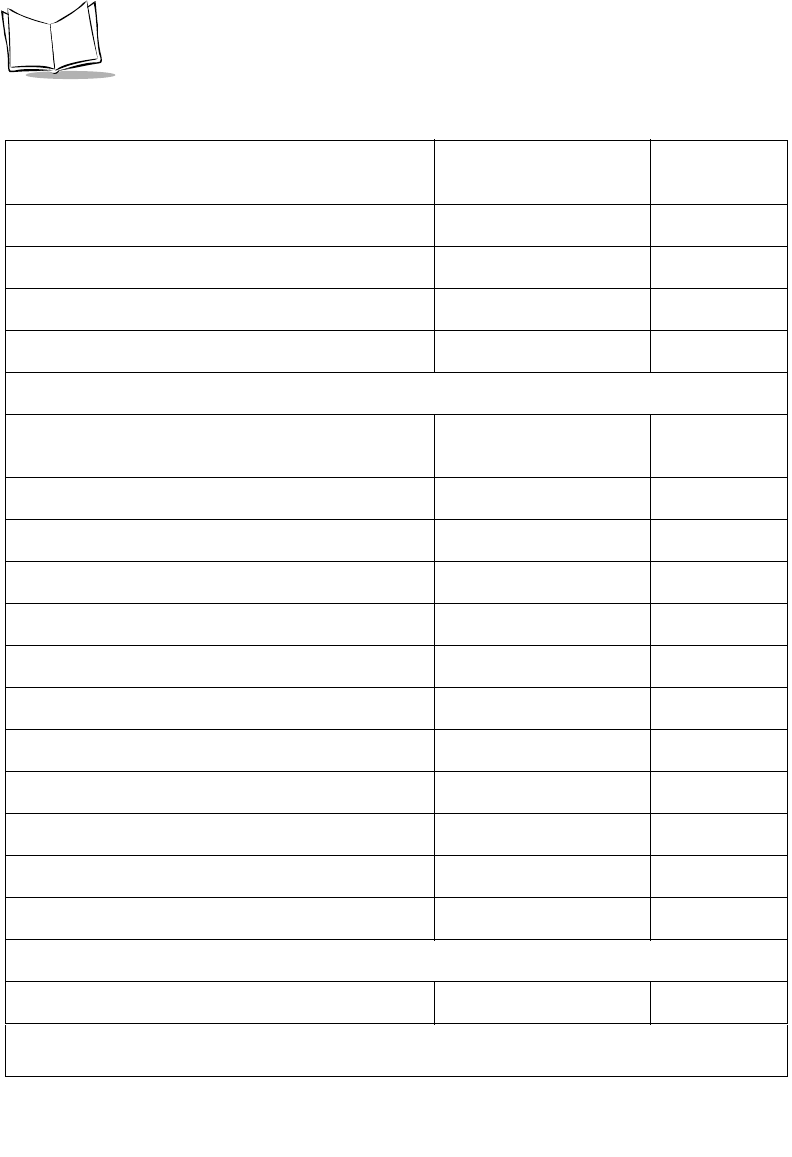
A-2
Symbol LS9208 Product Reference Guide
Time-out Between Same Symbol 0.6 sec 4-15
Time-out Between Different Symbols 0.2 sec 4-15
Time Delay to Low Power Mode 30 Minutes 4-16
Linear UPC/EAN Decode Disable 4-18
Keyboard Wedge Host Parameters
Keyboard Wedge Host Type IBM PC/AT& IBM PC
Compatibles15-4
Country Types (Country Codes) North American 5-6
Ignore Unknown Characters Transmit 5-10
Keystroke Delay No Delay 5-11
Inter-Keystroke Delay Disable 5-12
Alternate Numeric Keypad Emulation Disable 5-13
Caps Lock On Disable 5-14
Caps Lock Override Disable 5-15
Convert Wedge Data No Convert 5-16
Function Key Mapping Disable 5-17
FN1 Substitution Disable 5-18
Send Make Break Disable 5-19
RS-232 Host Parameters
RS-232 Host Types Standard16-7
Table A-1. Standard Default Parameters Table (Continued)
Parameter Default Page
Number
1User selection is required to configure this interface and this is the most common selection.
A-3
Standard Default Parameters
Baud Rate 9600 6-10
Parity None 6-12
Check Receive Errors Enable 6-14
Hardware Handshaking None 6-15
Software Handshaking None 6-18
Host Serial Response Time-out 2 Sec 6-21
RTS Line State Low RTS 6-23
Stop Bit Select 1 6-24
Data Bits 8-Bit 6-25
Beep on <BEL> Disable 6-26
Intercharacter Delay 0 msec 6-27
Nixdorf Beep/LED Options Normal Operation 6-29
Ignore Unknown Characters Send Bar Codes 6-30
USB Host Parameters
USB Device Type HID (Human Interface
Device) Keyboard
Emulation
7-5
USB Country Keyboard Types (Country Codes) North American 7-8
USB Keystroke Delay No Delay 7-12
USB CAPS Lock Override Disable 7-13
Table A-1. Standard Default Parameters Table (Continued)
Parameter Default Page
Number
1User selection is required to configure this interface and this is the most common selection.
A-4
Symbol LS9208 Product Reference Guide
USB Ignore Enable Transmission Enable 7-13
Emulate Keypad Disable 7-15
USB Keyboard FN1 Substitution Disable 7-16
Function Key Mapping Disable 7-17
Simulated Caps Lock Disable 7-18
Convert Case Disable 7-19
IBM 468X/469X Host Parameters
Port Address None Selected18-4
Convert Unknown Bar Code 39 Disable 8-6
Wand Emulation Host Parameters
Wand Emulation Host Types Symbol OmniLink
Interface Controller19-4
Leading Margin 80 msec 9-5
Polarity Bar High/Margin Low 9-6
Ignore Unknown Characters Transmit 9-7
Convert All Bar Codes to Code 39 Disable 9-8
Convert Code 39 to Full ASCII Disable 9-9
123Scan Configuration Tool
123Scan None110-2
Table A-1. Standard Default Parameters Table (Continued)
Parameter Default Page
Number
1User selection is required to configure this interface and this is the most common selection.

A-5
Standard Default Parameters
UPC/EAN
UPC-A Enable 11-8
UPC-E Enable 11-8
UPC-E1 Disable 11-9
EAN-8/JAN-8 Enable 11-10
EAN-13/JAN-13 Enable 11-10
Bookland EAN Disable 11-11
Decode UPC/EAN Supplementals (2 and 5 digits) Ignore 11-12
Decode UPC/EAN Supplemental Redundancy 20 11-19
Transmit UPC-A Check Digit Transmit 11-20
Transmit UPC-E Check Digit Transmit 11-20
Transmit UPC-E1 Check Digit Transmit 11-21
UPC-A Preamble System Character 11-22
UPC-E Preamble System Character 11-23
UPC-E1 Preamble System Character 11-24
Convert UPC-E to A Disable 11-25
Convert UPC-E1 to A Disable 11-26
EAN-8 Zero Extend Disable 11-27
Bookland ISBN Format ISBN-10 11-28
Table A-1. Standard Default Parameters Table (Continued)
Parameter Default Page
Number
1User selection is required to configure this interface and this is the most common selection.
A-6
Symbol LS9208 Product Reference Guide
UCC Coupon Extended Code Disable 11-29
Code 128
Code 128 Enable 11-30
UCC/EAN-128 Enable 11-31
ISBT 128 (non-concatenated) Enable 11-32
Code 128 Decode Performance Enable 11-33
Code 128 Decode Performance Level Level 3 11-34
Code 39
Code 39 Enable 11-35
Trioptic Code 39 Disable 11-36
Convert Code 39 to Code 32 (Italian Farmer Code) Disable 11-37
Code 32 Prefix Disable 11-38
Set Length(s) for Code 39 2 to 55 11-39
Code 39 Check Digit Verification Disable 11-41
Transmit Code 39 Check Digit Do Not Transmit 11-42
Code 39 Full ASCII Conversion Disable 11-43
Buffer Code 39 Disable 11-44
Code 39 Decode Performance Enable 11-48
Code 39 Decode Performance Level Level 3 11-49
Table A-1. Standard Default Parameters Table (Continued)
Parameter Default Page
Number
1User selection is required to configure this interface and this is the most common selection.
A-7
Standard Default Parameters
Code 93
Code 93 Disable 11-50
Set Length(s) for Code 93 4 to 55 11-51
Code 11
Code 11 Disable 11-53
Set Lengths for Code 11 4 to 55 11-54
Code 11 Check Digit Verification Disable 11-56
Transmit Code 11 Check Digit Do Not Transmit 11-57
Interleaved 2 of 5 (ITF)
Interleaved 2 of 5 (ITF) Disable 11-58
Set Length(s) for I 2 of 5 14 11-59
I 2 of 5 Check Digit Verification Disable 11-61
Transmit I 2 of 5 Check Digit Do Not Transmit 11-62
Convert I 2 of 5 to EAN 13 Disable 11-63
Discrete 2 of 5 (DTF)
Discrete 2 of 5 Disable 11-64
Set Length(s) for D 2 of 5 12 11-65
Chinese 2 of 5
Enable/Disable Chinese 2 of 5 Disable 11-67
Table A-1. Standard Default Parameters Table (Continued)
Parameter Default Page
Number
1User selection is required to configure this interface and this is the most common selection.
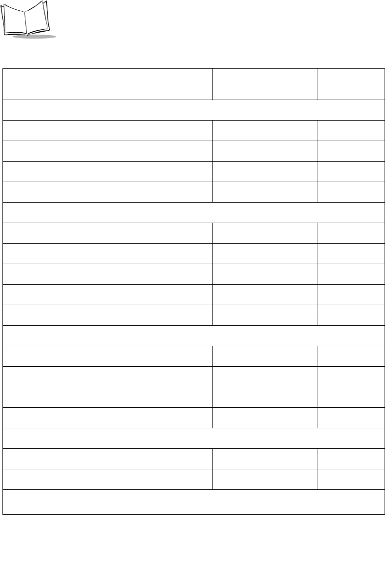
A-8
Symbol LS9208 Product Reference Guide
Codabar (NW - 7)
Codabar Disable 11-68
Set Lengths for Codabar 5 to 55 11-69
CLSI Editing Disable 11-71
NOTIS Editing Disable 11-72
MSI
MSI Disable 11-73
Set Length(s) for MSI 1 to 55 11-74
MSI Check Digits One 11-76
Transmit MSI Check Digit Disable 11-77
MSI Check Digit Algorithm Mod 10/Mod 10 11-78
RSS (Reduced Space Symbology)
RSS 14 Enable 11-79
RSS Limited Disable 11-80
RSS Expanded Enable 11-81
Convert RSS to UPC/EAN Disable 11-82
Symbology - Specific Security Levels
Redundancy Security Levels 1 11-85
Security Level 0 11-88
Table A-1. Standard Default Parameters Table (Continued)
Parameter Default Page
Number
1User selection is required to configure this interface and this is the most common selection.
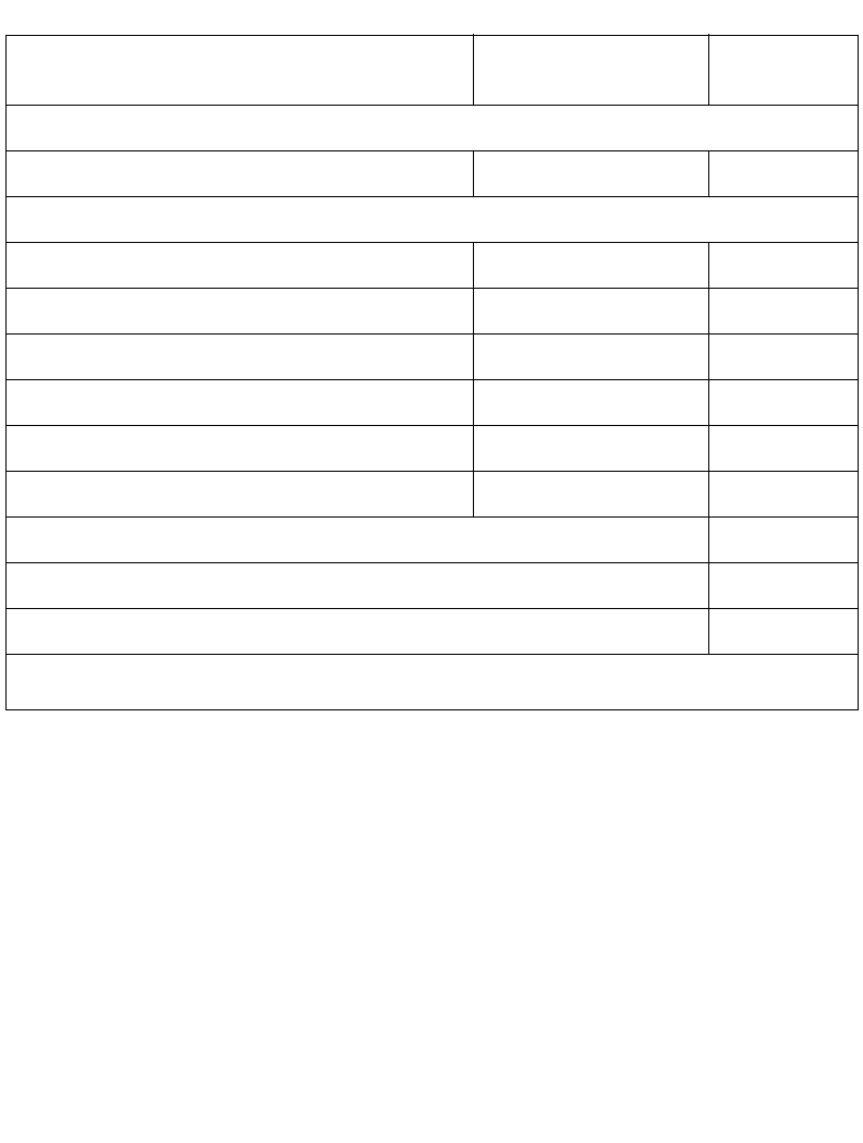
A-9
Standard Default Parameters
Symbology - Intercharacter Gap
Intercharacter Gaps Normal 11-90
Miscellaneous Scanner Options
Transmit Code ID Character Disable 12-4
Suffix Value (Value 1) <CR><LF> 12-5
Prefix Value (Value 2) None 12-5
FN1 Substitution Values 7013 12-8
Scan Data Options Data as is 12-9
Transmit “No Read” Message Disable 12-12
Report Version 12-13
Report MIMIC Version 12-13
Report Synapse Cable 12-13
Table A-1. Standard Default Parameters Table (Continued)
Parameter Default Page
Number
1User selection is required to configure this interface and this is the most common selection.

A-10
Symbol LS9208 Product Reference Guide

B-1
Appendix B
Programming Reference
Symbol Code Identifiers
Table B-1. Code Characters
Code Character Code Type
A UPC/EAN
B Code 39, Code 39 Full ASCII, Code 32
C Codabar
D Code 128, ISBT 128
E Code 93
F Interleaved 2 of 5
G Discrete 2 of 5, IATA
H Code 11
J MSI Plessey
K UCC/EAN-128
L Bookland EAN

B-2
Symbol LS9208 Product Reference Guide
M Code 39 Trioptic
N Coupon Code
RRSS
Table B-1. Code Characters (Continued)
Code Character Code Type

B-3
Programming Reference
AIM Code Identifiers
Each AIM Code Identifier contains the three-character string ]cm where:
]=Flag Character (ASCII 93)
c=Code Character
m=Modifier Character
Table B-2. AIM Code Characters
Code Character Code Type
A Code 39, Code 39 Full ASCII, Code 32
C Code 128 (all variants), Coupon (Code 128 portion)
E UPC/EAN, Coupon (UPC/EAN portion)
F Codabar
G Code 93
H Code 11
I Interleaved 2 of 5
M MSI Plessey
S Discrete 2 of 5, IATA
X Bookland EAN, Code 39 Trioptic
eRSS
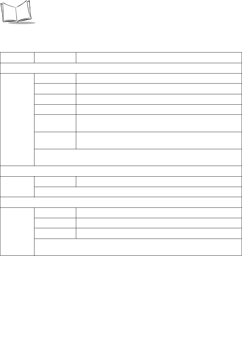
B-4
Symbol LS9208 Product Reference Guide
The modifier character is the sum of the applicable option values based on Table B-3.
Table B-3. Modifier Characters
Code Type Option Value Option
Code 39
0 No Check character.
1 Reader has checked one check character.
3 Reader has checked and stripped check character.
4 Reader has performed Full ASCII character conversion.
5 Reader has performed Full ASCII character conversion and
checked one check character.
7 Reader has performed Full ASCII character conversion and
checked and stripped check character.
Example: A Full ASCII bar code with check character W, A+I+MI+DW, is transmitted
as ]A7AimId where 7 = (3+4).
Trioptic Code 39
0 No option specified at this time. Always transmit 0.
Example: A Trioptic bar code 412356 is transmitted as ]X0412356
Code 128
0 Standard data packet, No Function code 1 in first symbol position.
1 Function code 1 in first symbol character position.
2 Function code 1 in second symbol character position.
Example: A Code (EAN) 128 bar code with Function 1 character in the first position,
FNC1 Aim Id is transmitted as ]C1AimId

B-5
Programming Reference
I 2 of 5
0 No check digit processing.
1 Reader has validated check digit.
3 Reader has validated and stripped check digit.
Example: An I 2 of 5 bar code without check digit, 4123, is transmitted as ]I04123
Codabar
0 Standard Codabar
1 ABC Codabar
Example: A standard Codabar bar code, 4123, is transmitted as ]F04123
Code 93
0 No options specified at this time. Always transmit 0.
Example: A Code 93 bar code 012345678905 is transmitted as ]G0012345678905
MSI Plessey
0 Mod 10 check digit validated and transmitted.
1 Mod 10 check digit validated but not transmitted.
Example: An MSI Plessey bar code 4123, with Mod 10 check digit validated, is
transmitted as ]M04123
D 2 of 5
0 No options specified at this time. Always transmit 0.
Example: A D 2 of 5 bar code 4123, is transmitted as ]S04123
Table B-3. Modifier Characters
Code Type Option Value Option
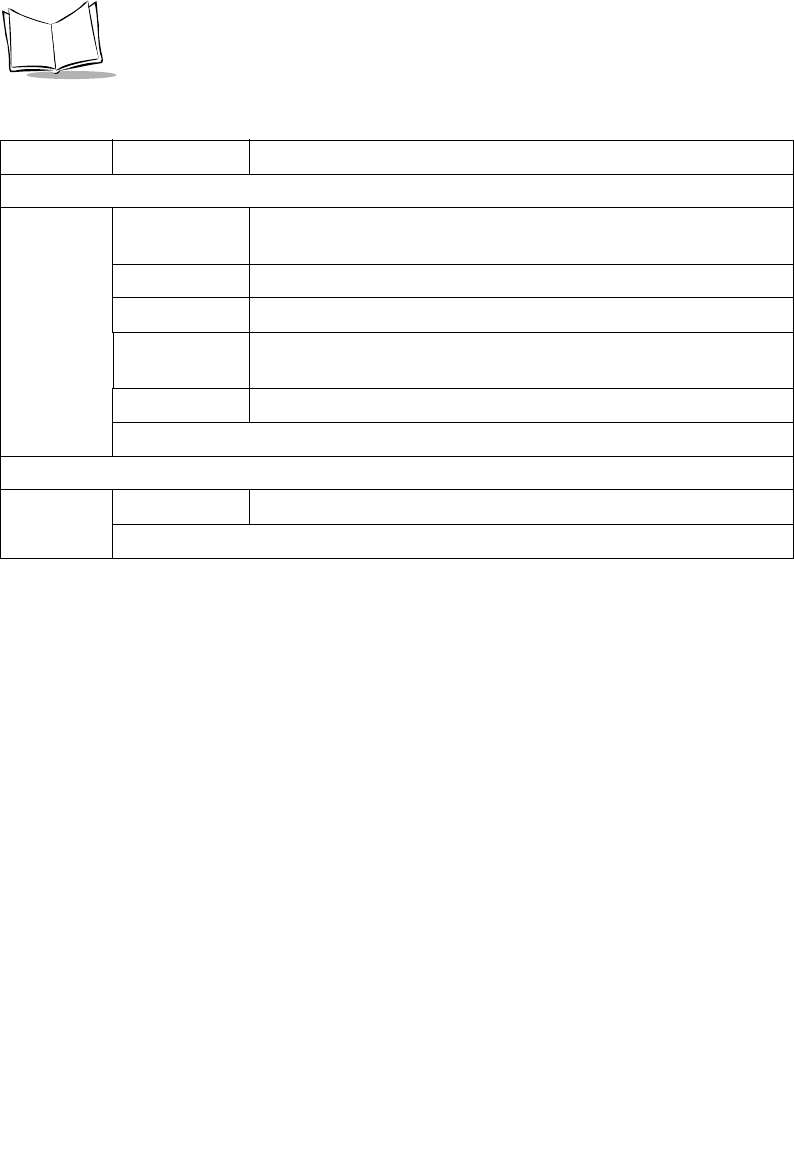
B-6
Symbol LS9208 Product Reference Guide
UPC/EAN
0 Standard packet in full EAN country code format, which is 13 digits
for UPC-A, UPC-E, and EAN-13 (not including supplemental data).
1 Two digit supplement data only.
2 Five digit supplement data only.
3 Combined data packet comprising 13 digits from a UPC-A, UPC-E,
or EAN-13 symbol and 2 or 5 digits from a supplemental symbol.
4 EAN-8 data packet.
Example: A UPCA bar code 012345678905 is transmitted as ]E00012345678905
Bookland EAN
0 No options specified at this time. Always transmit 0.
Example: A Bookland EAN bar code 123456789X is transmitted as ]X0123456789X
Table B-3. Modifier Characters
Code Type Option Value Option

B-7
Programming Reference
RSS Family
No option specified at this time. Always transmit 0. RSS-14 and
RSS-Limited transmit with an Application Identifier “01”.
Note: In UCC/EAN-128 emulation mode, RSS is transmitted using
Code 128 rules (i.e., ]C1).
Example: An RSS-14 bar code 100123456788902 is transmitted as
]e001100123456788902.
Table B-3. Modifier Characters
Code Type Option Value Option

B-8
Symbol LS9208 Product Reference Guide
C-1
0
12
3
4
5
6
7
8
9
0
5
Appendix C
Sample Bar Codes
Code 39
UPC/EAN
UPC-A, 100 %
123ABC
C-2
Symbol LS9208 Product Reference Guide
UPC/EAN (Continued)
EAN-13, 100 %
Code 128
Interleaved 2 of 5
3
4
5
6
7
8
9
0
12
3
4
0
12345678901234567890123456789012345678901234
12345678901231


C-4
Symbol LS9208 Product Reference Guide

D-1
Appendix D
Numeric Bar Codes
0, 1
For parameters requiring specific numeric values, scan the appropriately numbered bar
code(s).
0
1
D-2
Symbol LS9208 Product Reference Guide
2, 3, 4
2
3
4

D-3
Numeric Bar Codes
5, 6, 7
5
6
7

D-4
Symbol LS9208 Product Reference Guide
8, 9
9
8

D-5
Numeric Bar Codes
Cancel
If you make an error or wish to change your selection, scan the bar code below.
Cancel

D-6
Symbol LS9208 Product Reference Guide

Glossary-1
Glossary
Aperture The opening in an optical system defined by a lens or baffle that
establishes the field of view.
AIM The Automatic Identification Manufacturers Inc., a trade association.
ASCII American Standard Code for Information Interchange. A 7 bit-plus-
parity code representing 128 letters, numerals, punctuation marks,
and control characters. It is a standard data transmission code in the
U.S.
Autodiscrimination The ability of an interface controller to determine the code type of a
scanned bar code. After this determination is made, the information
content is decoded.
Bar The dark element in a printed bar code symbol.
Bar Code Density The number of characters represented per unit of measurement
(e.g., characters per inch).
Bar Height The dimension of a bar measured perpendicular to the bar width.
Bar Width Thickness of a bar measured from the edge closest to the symbol start
character to the trailing edge of the same bar.
Baud Rate A measure of the data flow or number of signaling events occurring
per second. When one bit is the standard "event," this is a measure of
bits per second (bps). For example, a baud rate of 50 means
transmission of 50 bits of data per second.
Bit Binary digit. One bit is the basic unit of binary information. Generally,
eight consecutive bits compose one byte of data. The pattern of 0 and
1 values within the byte determines its meaning.

Glossary-2
Symbol LS9208 Product Reference Guide
Byte On an addressable boundary, eight adjacent binary digits (0 and 1)
combined in a pattern to represent a specific character or numeric
value. Bits are numbered from the right, 0 through 7, with bit 0 the low-
order bit. One byte in memory is used to store one ASCII character.
CDRH Center for Devices and Radiological Health. A federal agency
responsible for regulating laser product safety. This agency specifies
various laser operation classes based on power output during
operation.
CDRH Class 1 This is the lowest power CDRH laser classification. This class is
considered intrinsically safe, even if all laser output were directed into
the eye's pupil. There are no special operating procedures for this
class.
CDRH Class 2 No additional software mechanisms are needed to conform to this
limit. Laser operation in this class poses no danger for unintentional
direct human exposure.
Character A pattern of bars and spaces which either directly represents data or
indicates a control function, such as a number, letter, punctuation
mark, or communications control contained in a message.
Character Set Those characters available for encoding in a particular bar code
symbology.
Check Digit A digit used to verify a correct symbol decode. The scanner inserts the
decoded data into an arithmetic formula and checks that the resulting
number matches the encoded check digit. Check digits are required
for UPC but are optional for other symbologies. Using check digits
decreases the chance of substitution errors when a symbol is
decoded.
Codabar A discrete self-checking code with a character set consisting of digits
0 to 9 and six additional characters: ( - $ : / , +).
Code 128 A high density symbology which allows the controller to encode all 128
ASCII characters without adding extra symbol elements.
Code 3 of 9 (Code
39) A versatile and widely used alphanumeric bar code symbology with a
set of 43 character types, including all uppercase letters, numerals
from 0 to 9, and 7 special characters (- . / + % $ and space). The code
name is derived from the fact that 3 of 9 elements representing a
character are wide, while the remaining 6 are narrow.
Code 93 An industrial symbology compatible with Code 39 but offering a full
character ASCII set and a higher coding density than Code 39.

Glossary-3
Glossary
Code Length Number of data characters in a bar code between the start and stop
characters, not including those characters.
Continuous Code A bar code or symbol in which all spaces within the symbol are parts
of characters. There are no intercharacter gaps in a continuous code.
The absence of gaps allows for greater information density.
Dead Zone An area within a scanner's field of view, in which specular reflection
may prevent a successful decode.
Decode To recognize a bar code symbology (e.g., UPC/EAN) and then
analyze the content of the specific bar code scanned.
Decode Algorithm A decoding scheme that converts pulse widths into data
representation of the letters or numbers encoded within a bar code
symbol.
Depth of Field The range between minimum and maximum distances at which a
scanner can read a symbol with a certain minimum element width.
Discrete Code A bar code or symbol in which the spaces between characters
(intercharacter gaps) are not part of the code.
Discrete 2 of 5 A binary bar code symbology representing each character by a group
of five bars, two of which are wide. The location of wide bars in the
group determines which character is encoded; spaces are
insignificant. Only numeric characters (0 to 9) and START/STOP
characters may be encoded.
EAN European Article Number. This European/International version of the
UPC provides its own coding format and symbology standards.
Element dimensions are specified metrically. EAN is used primarily in
retail.
Element Generic term for a bar or space.
Encoded Area Total linear dimension occupied by all characters of a code pattern,
including start/stop characters and data.
Host Computer A computer that serves other terminals in a network, providing such
services as computation, database access, supervisory programs,
and network control.
IEC International Electrotechnical Commission. This international agency
regulates laser safety by specifying various laser operation classes
based on power output during operation.

Glossary-4
Symbol LS9208 Product Reference Guide
IEC (825) Class 1 This is the lowest power IEC laser classification. Conformity is
ensured through a software restriction of 120 seconds of laser
operation within any 1000 second window and an automatic laser
shutdown if the scanner's oscillating mirror fails.
Intercharacter Gap The space between two adjacent bar code characters in a discrete
code.
Interleaved Bar
Code A bar code in which characters are paired together, using bars to
represent the first character and the intervening spaces to represent
the second.
Interleaved 2 of 5 A binary bar code symbology representing character pairs in groups
of five bars and five interleaved spaces. Interleaving provides for
greater information density. The location of wide elements (bar/
spaces) within each group determines which characters are encoded.
This continuous code type uses no intercharacter spaces. Only
numeric (0 to 9) and START/STOP characters may be encoded.
LASER - Light
Amplification by
Stimulated
Emission of
Radiation
The laser is an intense light source. Light from a laser is all the same
frequency, unlike the output of an incandescent bulb. Laser light is
typically coherent and has a high energy density.
Laser Diode A gallium-arsenide semiconductor type of laser connected to a power
source to generate a laser beam. This laser type is a compact source
of coherent light.
LED Indicator A semiconductor diode (LED - Light Emitting Diode) used as an
indicator, often in digital displays. The semiconductor uses applied
voltage to produce light of a certain frequency determined by the
semiconductor's particular chemical composition.
MIL 1 mil = 1 thousandth of an inch.
Misread
(Misdecode) A condition which occurs when the data output of a reader or interface
controller does not agree with the data encoded within a bar code
symbol.
Nominal The exact (or ideal) intended value for a specified parameter.
Tolerances are specified as positive and negative deviations from this
value.
Nominal Size Standard size for a bar code symbol. Most UPC/EAN codes are used
over a range of magnifications (e.g., from 0.80 to 2.00 of nominal).
Parameter A variable that can have different values assigned to it.

Glossary-5
Glossary
Percent Decode The average probability that a single scan of a bar code would result
in a successful decode. In a well-designed bar code scanning system,
that probability should approach near 100%.
Print Contrast
Signal (PCS) Measurement of the contrast (brightness difference) between the bars
and spaces of a symbol. A minimum PCS value is needed for a bar
code symbol to be scannable. PCS = (RL - RD) / RL, where RL is the
reflectance factor of the background and RD the reflectance factor of
the dark bars.
Programming Mode The state in which a scanner is configured for parameter values. See
SCANNING MODE.
Quiet Zone A clear space, containing no dark marks, which precedes the start
character of a bar code symbol and follows the stop character.
Reflectance Amount of light returned from an illuminated surface.
Resolution The narrowest element dimension which is distinguished by a
particular reading device or printed with a particular device or method.
RSS Reduced Space Symbology: A family of space efficient symbologies
developed by UCC.EAN.
Scan Area Area intended to contain a symbol.
Scanner An electronic device used to scan bar code symbols and produce a
digitized pattern that corresponds to the bars and spaces of the
symbol. Its three main components are:
1. Light source (laser or photoelectric cell) - illuminates a bar code.
2. Photodetector - registers the difference in reflected light (more light
reflected from spaces).
3. Signal conditioning circuit - transforms optical detector output into a
digitized bar pattern.
Scanning Mode The scanner is energized, programmed, and ready to read a bar code.
Scanning Sequence A method of programming or configuring parameters for a bar code
reading system by scanning bar code menus.
Self-Checking Code A symbology that uses a checking algorithm to detect encoding errors
within the characters of a bar code symbol.
Space The lighter element of a bar code formed by the background between
bars.
Specular Reflection The mirror-like direct reflection of light from a surface, which can
cause difficulty decoding a bar code.

Glossary-6
Symbol LS9208 Product Reference Guide
Start/Stop Character A pattern of bars and spaces that provides the scanner with start and
stop reading instructions and scanning direction. The start and stop
characters are normally to the left and right margins of a horizontal
code.
Substrate A foundation material on which a substance or image is placed.
Symbol A scannable unit that encodes data within the conventions of a certain
symbology, usually including start/stop characters, quiet zones, data
characters, and check characters.
Symbol Aspect
Ratio The ratio of symbol height to symbol width.
Symbol Height The distance between the outside edges of the quiet zones of the first
row and the last row.
Symbol Length Length of symbol measured from the beginning of the quiet zone
(margin) adjacent to the start character to the end of the quiet zone
(margin) adjacent to a stop character.
Symbology The structural rules and conventions for representing data within a
particular bar code type (e.g. UPC/EAN, Code 39).
Tolerance Allowable deviation from the nominal bar or space width.
UPC Universal Product Code. A relatively complex numeric symbology.
Each character consists of two bars and two spaces, each of which is
any of four widths. The standard symbology for retail food packages
in the United States.
Visible Laser Diode
(VLD) A solid state device which produces visible laser light.

Index-1
Numerics
123Scan parameters . . . . . . . . . . . . . . . . 10-2
A
actions . . . . . . . . . . . . . . . . . . . . . . . . . . . 13-2
ADF . . . . . . . . . . . . . . . . . . . . . . . . . . . . . . 13-1
actions . . . . . . . . . . . . . 13-1, 13-33, 13-34
move cursor . . . . . . . . . 13-43, 13-44
send data . . . . . . . . . . . . . . . . . 13-34
alphanumeric keyboard . . 13-178, 13-179
alternate rule sets . . . . . . . . . . . . . . . 13-4
bar code menu example . . . . . . . . . . 13-2
beep . . . . . . . . . . . . . . . . . . . 13-76, 13-77
code lengths . . . . . . . . . . . . . . . . . . 13-20
code types . . . . . . . . . . . . . . . . . . . . 13-12
criteria . . . . . . . . . . . . . . . . . . 13-1, 13-12
default rules . . . . . . . . . . . . . . . . . . . . 13-6
move cursor past a character . . . . . 13-42
move cursor to a character . . . . . . . 13-42
move cursor to start of data . . . . . . . 13-42
pad spaces . . . . . . . . . . . . . . . . . . . 13-55
pad zeros . . . . . . . . . . 13-66, 13-67, 13-68
rules . . . . . . . . . . . . . . . . . . . . . . . . . . 13-1
rules hierarchy . . . . . . . . . . . . . . . . . . 13-5
send control characters . . . . . . . . . . 13-77
send function key . . . . . . . . . . . . . . 13-142
send keyboard
characters . . . . . . 13-88, 13-89, 13-90
send keypad characters . . . . . . . . 13-130
send preset value . . . . . . . . . . . . . . 13-42
send value . . . . . . . . . 13-51, 13-52, 13-53
skip ahead characters 13-44, 13-46, 13-47
skip ahead "n" characters . . . . . . . . 13-42
skip back characters . 13-48, 13-50, 13-51
skip back "n" characters . . . . . . . . . 13-42
space removal . . . . . . . . . . . . . . . . 13-53
special commands . . . . . . . . . . . . . . 13-7
specific data string . . . . . . . . . . . . . 13-30
specific string
any location . . . . . . . . . . . . . . . 13-31
any message ok . . . . . . . . . . . 13-31
at start . . . . . . . . . . . . . . . . . . . 13-30
rule belongs to set . . . . . 13-32, 13-33
turn off rule sets . 13-175, 13-176, 13-177
zero removal . . . . . . . . . . . . . . . . . . 13-53
advanced data formatting . . . . . . . . . . . . 13-1
actions . . . . . . . . . . . . . . . . . . 13-1, 13-33
alphanumeric keyboard . . 13-178, 13-179
alternate rule sets . . . . . . . . . . . . . . . 13-4
bar code menu example . . . . . . . . . . 13-2
beep . . . . . . . . . . . . . . . . . . . 13-76, 13-77
code lengths . . . . . . . . . . . . . . . . . . 13-20
code types . . . . . . . . . . . . . . . . . . . 13-12
criteria . . . . . . . . . . . . . . . . . . . 13-1, 13-12
default rules . . . . . . . . . . . . . . . . . . . 13-6
pad spaces . . . . . . . . . . . . . . . . . . . 13-55
pad zeros . . . . . . . . . 13-66, 13-67, 13-68
rules . . . . . . . . . . . . . . . . . . . . . . . . . 13-1
rules hierarchy . . . . . . . . . . . . . . . . . 13-5
send control characters . . . . . . . . . 13-77
send function key . . . . . . . . . . . . . 13-142
send keyboard
characters . . . . . 13-88, 13-89, 13-90
send keypad characters . . . . . . . . 13-130
send preset value . . . 13-51, 13-52, 13-53
skip ahead characters 13-44, 13-46, 13-47
skip back characters . 13-48, 13-50, 13-51
Index

Index-2
Symbol LS9208 Product Reference Guide
space removal . . . . . . . . . . . . . . . . 13-53
special commands . . . . . . . . . . . . . . 13-7
specific data string . . . . . . . . . . . . . 13-30
turn off rule sets . 13-175, 13-176, 13-177
zero removal . . . . . . . . . . . . . . . . . . 13-53
AIM code identifiers . . . . . . . . . . . . . . . . . . B-3
aiming . . . . . . . . . . . . . . . . . . . . . . . 2-10, 2-11
ASCII values . . . . . . . . . . . . . . . . . . . . . . 6-31
B
bar codes
123Scan . . . . . . . . . . . . . . . . . . . . . . 10-2
beep after good decode . . . . . . . . . . 4-10
beeper tone . . . . . . . . . . . . . . . . . . . . . 4-6
beeper volume . . . . . . . . . . . . . . . . . . 4-7
bookland EAN . . . . . . . . . . . . . . . . . 11-11
bookland ISBN . . . . . . . . . . . . . . . . 11-28
buffering . . . . . . . . . . . . . . . . . . . . . 11-44
chinese 2 of 5 . . . . . . . . . . . . . . . . . 11-67
codabar . . . . . . . . . . . . . . . . . . . . . . 11-68
codabar CLSI editing . . . . . . . . . . . 11-71
codabar lengths . . . . . . . . . . . . . . . 11-69
codabar NOTIS editing . . . . . . . . . . 11-72
code 11 . . . . . . . . . . . . . . . . . . . . . . 11-53
code 11 check digit verification . . . . 11-56
code 11 check digits . . . . . . . . . . . . 11-57
code 11 lengths . . . . . . . . . . . . . . . 11-54
code 128 . . . . . . . . . . . . . . . . . . . . . 11-30
code 128 decode performance . . . . 11-33
code 128 decode performance level 11-34
code 32 prefix . . . . . . . . . . . . . . . . . 11-38
code 39 . . . . . . . . . . . . . . . . . . . . . . 11-35
code 39 check digit verification . . . . 11-41
code 39 decode performance . . . . . 11-48
code 39 decode performance level . 11-49
code 39 full ASCII . . . . . . . . . . . . . . 11-43
code 39 lengths . . . . . . . . . . . . . . . 11-39
code 39 transmit buffer . . . . . . . . . . 11-46
code 39 transmit check digit . . . . . . 11-42
code 93 . . . . . . . . . . . . . . . . . . . . . . 11-50
code 93 lengths . . . . . . . . . . . . . . . 11-51
convert code 39 to code 32 . . . . . . 11-37
convert RSS to UPC/EAN . . . . . . . . 11-82
convert UPC-E to UPC-A . . . . . . . . . 11-25
convert UPC-E1 to UPC-A . . . . . . . . 11-26
data options . . . . . . . . . . . . . . . . . . . . 12-4
pause duration . . . . . . . . . . . . . . 13-7
prefix/suffix values . . . . . . . . . . . 12-5
transmit code ID character . . . . . 12-4
discrete 2 of 5 . . . . . . . . . . . . . . . . . 11-64
discrete 2 of 5 lengths . . . . . . . . . . . 11-65
EAN zero extend . . . . . . . . . . . . . . . 11-27
EAN-13/EAN-8 . . . . . . . . . . . . . . . . . 11-10
EAN-8 . . . . . . . . . . . . . . . . . . . . . . . 11-11
I 2 of 5 check digit verification . . . . . 11-61
I 2 of 5 convert to EAN-13 . . . . . . . . 11-63
I 2 of 5 transmit check digit . . . . . . . 11-62
IBM 468X/469X
convert unkown to code 39 . . . . . . 8-6
default parameters . . . . . . . . . . . . 8-3
port address . . . . . . . . . . . . . . . . . 8-4
intercharacter gap . . . . . . . . . . . . . . 11-90
interleaved 2 of 5 . . . . . . . . . . . . . . . 11-58
interleaved 2 of 5 lengths . . . . . . . . . 11-59
ISBT 128 . . . . . . . . . . . . . . . . . . . . . 11-32
keyboard wedge
alternate numeric keypad
emulation . . . . . . . . . . . 5-13
caps lock on . . . . . . . . . . . . . . . . 5-14
capsl ock override . . . . . . . . . . . . 5-15
country keyboard types
(country codes) . . . . . . . . 5-6
default table . . . . . . . . . . . . . . . . . 5-3
host types . . . . . . . . . . . . . . . 5-4, 5-5
ignore unknown characters . . . . . 5-10
intra-keystroke delay . . . . . . . . . . 5-12
keystroke delay . . . . . . . . . . . . . . 5-11
laser on time . . . . . . . . . . . . . . . . . . . . 4-9
miscellaneous
scan data options . . . . . . . . . . . . 12-9
transmit no read msg . . . . . . . . 12-12
MSI . . . . . . . . . . . . . . . . . . . . . . . . . . 11-73
MSI check digit algorithm . . . . . . . . . 11-78
MSI check digits . . . . . . . . . . . . . . . . 11-76
MSI lengths . . . . . . . . . . . . . . . . . . . 11-74
MSI transmit check digit . . . . . . . . . . 11-77
numeric bar codes . . . . . . . . . . . . . . . .D-5

Index-3
Index
redundancy level . . . . . . . . . . . . . . . 11-85
report mimic version . . . . . . . . . . . . 12-13
report synapse cable . . . . . . . . . . . . 12-13
report version . . . . . . . . . . . . . . . . . . 12-13
RS-232
ASCII format . . . . . . . . . . . . . . . . 6-25
baud rate . . . . . . . . . . . . . . . . . . 6-10
beep on bel . . . . . . . . . . . . . . . . . 6-26
check receive errors . . . . . . . . . . 6-14
default table . . . . . . . . . . . . . . . . . 6-3
hardware handshaking . . . . . . . . 6-15
host serial response time-out . . . 6-21
host types . . . . . . . . . . . . 6-7, 6-8, 6-9
intercharacter delay . . . . . . . . . . 6-27
parity . . . . . . . . . . . . . . . . . . . . . . 6-12
RTS line state . . . . . . . . . . . . . . . 6-23
software handshaking . . . . . . . . 6-18
stop bit select . . . . . . . . . . . . . . . 6-24
RSS . . . . . . . . . . . . . . . . . . . . . . . . . 11-79
RSS 14 . . . . . . . . . . . . . . . . . . . . . . 11-79
RSS expanded . . . . . . . . . . . . . . . . 11-81
RSS limited . . . . . . . . . . . . . . . . . . . 11-80
security level . . . . . . . . . . . . . . . . . . 11-88
set defaults . . . . . . . . . . . . . . . . . . . . . 4-5
supplementals . . . . . . . . . . . . . . . . . 11-12
symbologies
default table . . . . . . . . . . . . . . . . 11-3
trioptic code 39 . . . . . . . . . . . . . . . . 11-36
UCC coupon extended code . . . . . . 11-29
UCC/EAN-128 . . . . . . . . . . . . . . . . . 11-31
UPC-A preamble . . . . . . . . . . . . . . . 11-22
UPC-A/E/E1 check digit . . . . . . . . . . 11-20
UPC-A/UPC-E . . . . . . . . . . . . . . . . . . 11-8
UPC-E . . . . . . . . . . . . . . . . . . . . . . . . 11-9
UPC-E preamble . . . . . . . . . . . . . . . 11-23
UPC-E1 . . . . . . . . . . . . . . . . . . . . . . . 11-9
UPC-E1 preamble . . . . . . . . . . . . . . 11-24
UPC/EAN
coupon code . . . . . . . . . . . . . . . 11-29
UPC/EAN supp redundancy . . . . . . 11-19
USBcaps lock override . . . . . . . . . . . 7-13
country keyboard types . . . . . . . . 7-8
default table . . . . . . . . . . . . . . . . . 7-4
device type . . . . . . . . . . . . . . . . . 7-5
keystroke delay . . . . . . . . . . . . . 7-12
unknown characters . . . . . . . . . 7-14
wand emulation
code 39 full ASCII . . . . . . . . . . . . 9-9
convert all bar codes to code 39 . 9-8
default table . . . . . . . . . . . . . . . . . 9-3
host types . . . . . . . . . . . . . . . . . . 9-4
leading margin (quiet zone) . . . . . 9-5
polarity . . . . . . . . . . . . . . . . . . . . . 9-6
unknown characters . . . . . . . . . . 9-7
C
cables
installing . . . . . . . . . . . . . . . . . . . . . . . 1-3
interface . . . . . . . . . . . . . . . . . . . . . . . 1-4
removing cables . . . . . . . . . . . . . . . . . 1-7
character set . . . . . . . . . . . . . . . . . . . . . . 6-31
chinese 2 of 5 . . . . . . . . . . . . . . . . . . . . . 11-67
codabar . . . . . . . . . . . . . . . . . . . . . . . . . 11-68
CLSI editing . . . . . . . . . . . . . . . . . . 11-71
lengths . . . . . . . . . . . . . . . . . . . . . . 11-69
NOTIS editing . . . . . . . . . . . . . . . . . 11-72
code 11 . . . . . . . . . . . . . . . . . . . . . . . . . 11-53
check digit verification . . . . . . . . . . . 11-56
lengths . . . . . . . . . . . . . . . . . . . . . . 11-54
transmit check digits . . . . . . . . . . . . 11-57
code 128 . . . . . . . . . . . . . . . . . . . . . . . . 11-30
decode performance . . . . . . . . . . . . 11-33
decode performance level . . . . . . . 11-34
ISBT 128 . . . . . . . . . . . . . . . . . . . . . 11-32
UCC/EAN-128 . . . . . . . . . . . . . . . . 11-31
code 39 . . . . . . . . . . . . . . . . . . . . . . . . . 11-35
buffering . . . . . . . . . . . . . . . . . . . . . 11-44
check digit verification . . . . . . . . . . . 11-41
code 32 prefix . . . . . . . . . . . . . . . . . 11-38
convert to code 32 . . . . . . . . . . . . . 11-37
decode performance . . . . . . . . . . . . 11-48
decode performance level . . . . . . . 11-49
full ASCII . . . . . . . . . . . . . . . . . . . . . 11-43
lengths . . . . . . . . . . . . . . . . . . . . . . 11-39
transmit buffer . . . . . . . . . . . . . . . . . 11-46
transmit check digit . . . . . . . . . . . . . 11-42

Index-4
Symbol LS9208 Product Reference Guide
trioptic . . . . . . . . . . . . . . . . . . . . . . . 11-36
code 93 . . . . . . . . . . . . . . . . . . . . . . . . . 11-50
lengths . . . . . . . . . . . . . . . . . . . . . . 11-51
code ID characters
AIM . . . . . . . . . . . . . . . . . . . . . . . . . . . B-3
code identifiers
Symbol code IDs . . . . . . . . . . . . . . . . . B-1
code types
ADF . . . . . . . . . . . . . . . . . . . . . . . . . 13-12
connecting power . . . . . . . . . . . . . . . . . . . . 1-4
customer interaction center . . . . . . . . . . . . . xv
D
default parameters . . . . . . . . . . . . . . . . . . . 4-3
IBM 468X/469X . . . . . . . . . . . . . . . . . . 8-3
keyboard wedge . . . . . . . . . . . . . . . . . 5-3
miscellaneous scanner options . . . . . 12-3
RS-232 . . . . . . . . . . . . . . . . . . . . . . . . 6-3
standard default table . . . . . . . . . . . . . A-1
symbologies . . . . . . . . . . . . . . . . . . . 11-3
USB . . . . . . . . . . . . . . . . . . . . . . . . . . 7-4
user preferences . . . . . . . . . . . . . . . . . 4-3
wand emulation . . . . . . . . . . . . . . . . . . 9-3
discrete 2 of 5 . . . . . . . . . . . . . . . . . . . . 11-64
lengths . . . . . . . . . . . . . . . . . . . . . . 11-65
H
host types
keyboard wedge . . . . . . . . . . . . . . 5-4, 5-5
RS-232 . . . . . . . . . . . . . . . . . 6-7, 6-8, 6-9
wand emulation . . . . . . . . . . . . . . . . . . 9-4
I
IBM 468X/469X connection . . . . . . . . . . . . 8-2
IBM 468X/469X default parameters . . . . . . 8-3
IBM 468X/469X parameters . . . . . . . . . . . . 8-4
intercharacter gap . . . . . . . . . . . . . . . . . 11-90
interleaved 2 of 5 . . . . . . . . . . . . . . . . . . 11-58
check digit verification . . . . . . . . . . . 11-61
convert to EAN-13 . . . . . . . . . . . . . 11-63
lengths . . . . . . . . . . . . . . . . . . . . . . 11-59
transmit check digit . . . . . . . . . . . . . 11-62
K
keyboard wedge connection . . . . . . . . . . . . 5-2
keyboard wedge default parameters . . . . . . 5-3
keyboard wedge parameters . . . . . . . . . . . . 5-4
M
maintenance . . . . . . . . . . . . . . . . . . . . . . . . 3-1
miscellaneous scanner parameters . . . . . 12-3
mounting template . . . . . . . . . . . . . . . . . . . 2-15
MSI . . . . . . . . . . . . . . . . . . . . . . . . . . . . . 11-73
check digit algorithm . . . . . . . . . . . . 11-78
check digits . . . . . . . . . . . . . . . . . . . 11-76
lengths . . . . . . . . . . . . . . . . . . . . . . . 11-74
transmit check digit . . . . . . . . . . . . . 11-77
N
notational conventions . . . . . . . . . . . . . . . . xiv
P
parameters
IBM 468X/469X . . . . . . . . . . . . . . . . . . 8-4
keyboard wedge . . . . . . . . . . . . . . . . . . 5-4
RS-232 . . . . . . . . . . . . . . . . . . . . . . . . . 6-5
USB . . . . . . . . . . . . . . . . . . . . . . . . . . . 7-5
wand emulation . . . . . . . . . . . . . . . . . . 9-4
parts . . . . . . . . . . . . . . . . . . . . . . . . . . . . . . 2-1
pinouts
scanner signal descriptions . . . . . . . . . 3-7
power supply
connecting . . . . . . . . . . . . . . . . . . . . . . 1-4
prefix/suffix values . . . . . . . . . . . . . . . . . . . 6-31
programming bar codes
time delay to low power
mode . . . . . . . . . . . . .4-16, 4-17, 4-18
timeout between decodes . . . . . . . . . 4-15
Q
quiet zone (leading margin) . . . . . . . . . . . . . 9-5
R
report mimic version . . . . . . . . . . . . . . . . 12-13

Index-5
Index
report synapse cable . . . . . . . . . . . . . . . 12-13
report version . . . . . . . . . . . . . . . . . . . . . 12-13
RS-232 connection . . . . . . . . . . . . . . . . . . . 6-3
RS-232 default parameters . . . . . . . . . . . . . 6-3
RS-232 parameters . . . . . . . . 6-5, 6-7, 6-8, 6-9
RSS . . . . . . . . . . . . . . . . . . . . . . . . . . . . 11-79
convert to UPC/EAN . . . . . . . . . . . . 11-82
RSS 14 . . . . . . . . . . . . . . . . . . . . . . 11-79
RSS expanded . . . . . . . . . . . . . . . . 11-81
RSS limited . . . . . . . . . . . . . . . . . . . 11-80
S
scanner defaults . . . . . . . . . . . . . . . . . . . . . 4-3
scanner parts . . . . . . . . . . . . . . . . . . . . . . . 2-1
scanning
aiming . . . . . . . . . . . . . . . . . . . 2-10, 2-11
errors . . . . . . . . . . . . . . . . . 4-2, 11-2, 12-2
hand-held . . . . . . . . . . . . . . . . . . . . . . 2-10
hands-free . . . . . . . . . . . . . . . . . . . . . . 2-3
sequence example . . . . . . 4-2, 11-2, 12-2
security
redundancy level . . . . . . . . . . . . . . . 11-85
security level . . . . . . . . . . . . . . . . . . 11-88
service information . . . . . . . . . . . . . . . . . . . . xv
setup
connecting a USB interface . . . . . . . . . 7-2
connecting an RS-232 interface . . . . . 6-3
connecting interface cable . . . . . . . . . . 1-4
connecting keyboard wedge interface . 5-2
connecting power . . . . . . . . . . . . . . . . 1-4
connecting power supply . . . . . . . . . . . 1-4
connecting to an IBM 468X/469X host 8-2
connecting using wand emulation . . . . 9-2
installing the cable . . . . . . . . . . . . . . . . 1-3
unpacking . . . . . . . . . . . . . . . . . . . . . . 1-2
signal descriptions . . . . . . . . . . . . . . . . . . . 3-7
specifications . . . . . . . . . . . . . . . . . . . . . . . 3-4
standard default parameters . . . . . . . . . . . . A-1
standard defaults . . . . . . . . . . . . . . . . . . . . 4-3
symbology default parameters . . . . . . . . . 11-3
T
technical specifications . . . . . . . . . . . . . . . 3-4
template, stand mounting . . . . . . . . . . . . . 2-15
U
unpacking . . . . . . . . . . . . . . . . . . . . . . . . . . 1-2
UPC/EAN
bookland EAN . . . . . . . . . . . . . . . . . 11-11
bookland ISBN . . . . . . . . . . . . . . . . 11-28
check digit . . . . . . . . . . . . . . . . . . . . 11-20
convert UPC-E to UPC-A . . . . . . . . 11-25
convert UPC-E1 to UPC-A . . . . . . . 11-26
EAN zero extend . . . . . . . . . . . . . . . 11-27
EAN-13/EAN-8 . . . . . . . . . . . . . . . . 11-10
EAN-8 . . . . . . . . . . . . . . . . . . . . . . . 11-11
supplemental redundancy . . . . . . . . 11-19
supplementals . . . . . . . . . . . . . . . . . 11-12
UCC coupon extended code . . . . . . 11-29
UPC-A preamble . . . . . . . . . . . . . . . 11-22
UPC-A/UPC-E . . . . . . . . . . . . . . . . . 11-8
UPC-E . . . . . . . . . . . . . . . . . . . . . . . . 11-9
UPC-E preamble . . . . . . . . . . . . . . . 11-23
UPC-E1 . . . . . . . . . . . . . . . . . . . . . . . 11-9
UPC-E1 preamble . . . . . . . . . . . . . . 11-24
USB connection . . . . . . . . . . . . . . . . . . . . . 7-2
USB default parameters . . . . . . . . . . . . . . . 7-4
USB parameters . . . . . . . . . . . . . . . . . . . . 7-5
user preferences parameters . . . . . . . . . . . 4-3
W
wand emulation connection . . . . . . . . . . . . 9-2
wand emulation default parameters . . . . . . 9-3
wand emulation parameters . . . . . . . . . . . . 9-4

Index-6
Symbol LS9208 Product Reference Guide

Thank you for your input—We value your comments.
Tell Us What You Think...
We’d like to know what you think about this Guide. Please take a moment
to fill out this questionnaire and fax this form to: (631) 738-3318, or mail to:
Motorola
One Symbol Plaza M/S B-10
Holtsville, NY 11742-1300
Attention:Technical Publications Manager
Advanced Data Capture Division
IMPORTANT: If you need product support, please call the appropriate
customer support number provided. Unfortunately, we cannot provide
customer support at the fax number above.
User’s Guide Title:___________________________________________
(please include revision level)
How familiar were you with this product before using this guide?
Did this guide meet your needs? If not, please explain.
___________________________________________________________
___________________________________________________________
What topics need to be added to the index, if applicable?
___________________________________________________________
___________________________________________________________
What topics do you feel need to be better discussed? Please be specific.
___________________________________________________________
___________________________________________________________
What can we do to further improve our guides?
___________________________________________________________
___________________________________________________________
Very familiar Slightly familiar Not at all familiar


72E-60833-05
Revision A - February 2007
Motorola
One Symbol Plaza
Holtsville, New York 11742-1300
http://www.symbol.com
