Users Manual
Copyright © 2008-2009 Movea. All rights reserved
EN-2008
MotionPod™
Users’ Guide

2
TABLE OF CONTENT
I. Terminology ...................................................................................................................................................................... 3
II. Product diagram .............................................................................................................................................................. 3
III. Safety rules ......................................................................................................................................................................... 4
IV. Introduction ....................................................................................................................................................................... 6
V. Get Familiar with MOTIONPOD™ .............................................................................................................................. 7
1. MOTIONPOD™ .............................................................................................................................................................. 7
2. The MotionController™ ............................................................................................................................................ 8
VI. Usage..................................................................................................................................................................................... 9
1. Recharging your MotionPod .................................................................................................................................. 9
2. How to switch the MotionPod on and off ...................................................................................................... 10
3. How to wear the MOTIONPOD™........................................................................................................................ 11
VII. Precautions ..................................................................................................................................................................... 11
1. Using environments ............................................................................................................................................... 11
2. Characteristics and environmental conditions ........................................................................................... 13
VIII. Calibration ....................................................................................................................................................................... 14
IX. Cleaning ............................................................................................................................................................................ 15
1. Cleaning the MOTIONCONTROLLER™ ............................................................................................................ 15
2. Cleaning the MOTIONPOD™ ................................................................................................................................ 15
X. Signs and labels ............................................................................................................................................................. 16
1. The MOTIONPOD™ .................................................................................................................................................. 16
2. The MOTIONCONTROLLER™ .............................................................................................................................. 16
XI. Maintenance ................................................................................................................................................................... 16
XII. What to do in case of system breakdown ........................................................................................................... 17
3
I. TERMINOLOGY
Code Name
Description
MPOD
MotionPod, designates the motion sensing case
MOTIONCONTROLLER™
MotionPod Controller or charger/data receiver, a MPOD device.
Designates data receiving and/or recharging case which connects on the
computer via USB port.
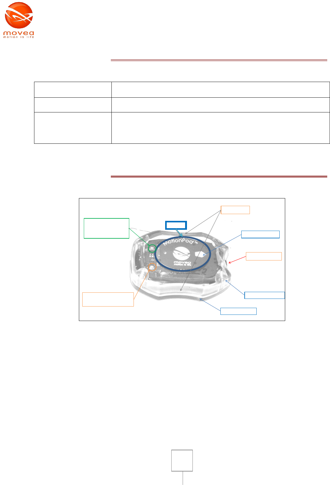
II. PRODUCT DIAGRAM
Antenna
Finger grips
On/Off button
Orange LED indicates
recharging
Green LED
indicates
transmission state
Transparent top cover
Black bottom cover
Orientation arrow
FIGURE 1 : CASING OF MOTIONPOD™
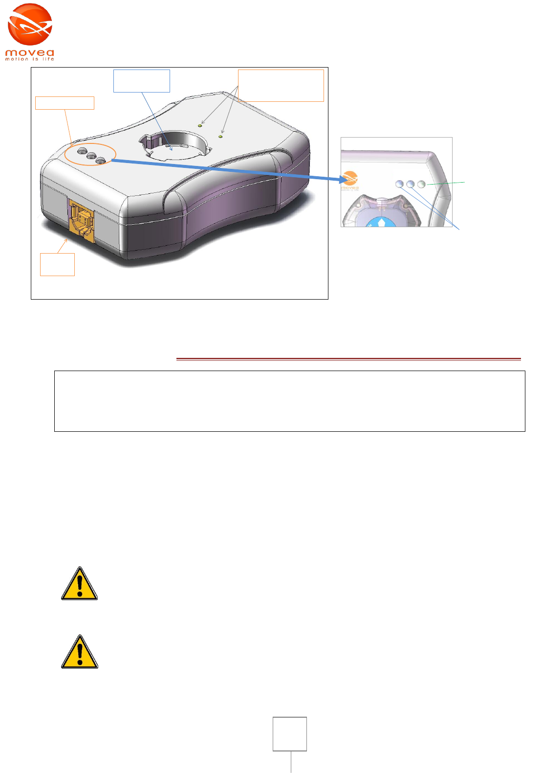
4
MPOD
charging cavity
Spring contacts for
electrical link with the
MPOD
Light indicators
USB
port
rx tx pwr
Green power light:
indicates that the
Motion Controller is
receiving power
Blue RX/TX lights:
RX signal reception
TX signal transmission
FIGURE 2 : MOTION CONTROLLER
III. SAFETY RULES
Warning
Please read this user’s guide very carefully before use.
Advise all recommendations to end-user and keep him informed of all risks endured using the
system.
MOTIONCONTROLLER™ must be plugged using equipment in compliance with INTO standard
60950-1 via USB2 port with the provided cable. In order to fulfill safety requirements for electro-
medical systems and equipments, power must be supplied by a transformer in compliance with the
EN standard 60601-1.
MOTIONPOD™ is the only part in contact with the patient, so by no means they’re to be in contact
with the MOTIONCONTROLLER™ or the computer during use. Patients are to be held at 1,20m to
1,60m away from this equipment.
Do not open or replace the Li-ion battery of the MOTIONPOD™. Do not use non
rechargeable battery or any other battery other than the one provided by
Movea. It could damage the product and presents health risks or cause
accidents.
DO NOT EXPOSE TO FIRE–Risk of explosion, DO NOT OPEN
5
CAUTION: For your own safety do not open the charging case, risk of electric shock.
Waste management process of electric and electronic products differs from that of municipal waste
and requires special intervention from waste management services appointed by the government or
the local community. The crossed trashcan shows that the European directive 2002/96/CE applies
to this product.
Waste separation prevents from any negative consequences on the environment or public health. It
is the most important condition for better handling and recycling electric and electronic
components. For more information about handling of worn out equipments, contact your local
waste management service or the nearest product distributor.
It is highly recommended not to connect any peripherals (modem, printers…) other than the
MOTIONCONTROLLER™ on the computer during the use of the system. The MOTIONPOD™ has a Li
Ion battery and therefore must be recycled according to current standards. It must be returned to
the manufacturer.

6
IV. INTRODUCTION
Thank you for purchasing our motion sensing product MotionPod™.
This user manual was written to familiarize you with the use of this system. Read it carefully in
order to rightfully use the device. Always have this guide near you when you use this product.
The MotionPod is an electronic goniometric recording device with wireless transmission. It was
conceived to provide “movement signature” of a body segment in real time and without cable
connection.
Its main purpose is to compare series of rehabilitation exercises with prior exercises, movement
amplitudes gestures protocols etc… carried out for limb rehabilitation (for example of joint
extensions).
This product designed and manufactured by Movea, is well adapted for biomechanical applications,
rehabilitation and joint assessment in physical therapy. For this reason, it must be used in a
controlled environment, at your work place, and by qualified personnel. The user of MotionPod
must have red and understood this notice.
The MOTIONPOD™ System is provided with software that must be the only software solution to be
used with this product.
7
V. GET FAMILIAR WITH MOTIONPOD™
Please take a moment to familiarize with the different components of your measuring system. For
the following section it is advised to refer to the material scheme II.
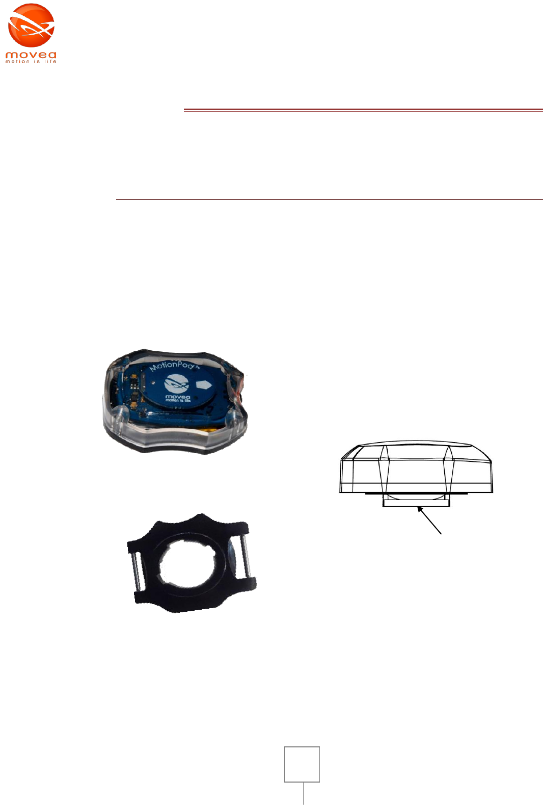
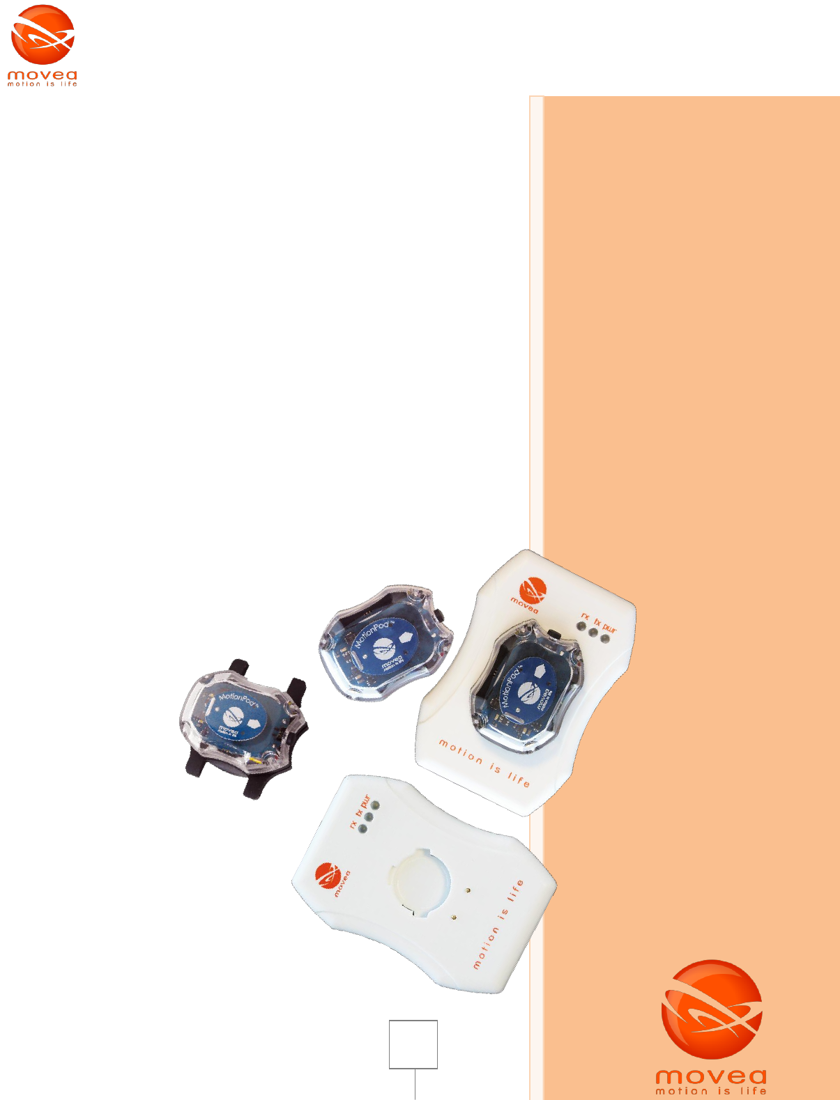
1. MOTIONPOD™
MOTIONPOD™ is standard wristwatch-sized sensor with a transparent casing that embodies the
Motion sensing component on the upper side (Figure 3). It is intended to be worn on the moving
part of the body where we want to perform joint assessment. It must be fixed mechanically by
means of straps or bracelets (not provided) via the black colored mechanical interface.
Photo of MotionPod™
Mechanical interface for bracelet or
strap
Side view of MOTIONPOD™ scheme
Mechanical fixing base
FIGURE 3 : MOTIONPOD™
On the top of MOTIONPOD™ you can see an ellipse shaped facet: it is the antenna with an imprinted
name and logo of the manufacturer (Movea, Motion is Life), the brand name of the product
(MotionPod) and an arrow pointing towards the button located on the side of the casing. The arrow
8
also indicates the exact orientation to fix the MOTIONPOD™ properly. Please be focused with these
elements for they are useful to establish the MOTIONPOD™ correctly in the application that is
provided with your system.
From a side view (see Figure 3, on the right), you can see a Black bottom cover of the MOTIONPOD™.
This part allows fixing the MOTIONPOD™ on any kind of supporting facet designed to accommodate
it. It can be the charging box (see below) or the mechanical interface for bracelet or strap.
Figure 1 summarizes the first visual elements on the MOTIONPOD™.
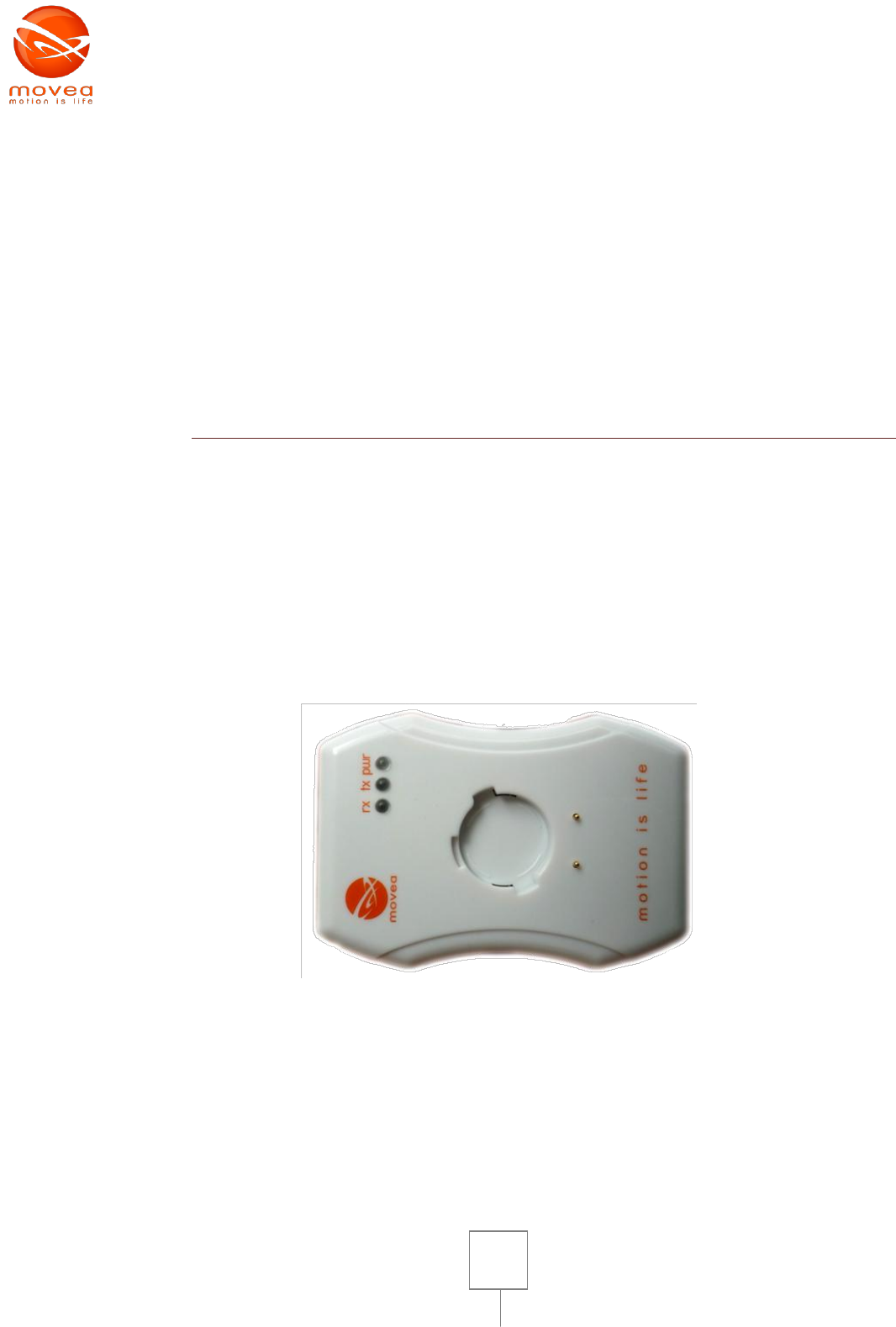
2. THE MOTIONCONTROLLER™
The MOTIONCONTROLLER™ is a white case with a surface identical to that of a credit card and
approximately 2cm thick (see Figure 4). On the upper facet you can see an imprinted logo of Movea,
and light indicator inscriptions (see below for their significance).
Connected on the PC via USB port cable (provided), it allows:
- Data reception transmitted from the MotionPod by radio frequency (Band ISM – 2.45 GHz)
- Charging of the MOTIONPOD™
Photo of the MotionController™
FIGURE 4 : MOTIONCONTROLLER™
The MOTIONCONTROLLER™ guarantees a wireless link between the MOTIONPOD™ and the
computer where you manage your applications. The data goes to the computer via USB cable.
9
VI. USAGE
1. RECHARGING YOUR MOTIONPOD™
The MOTIONCONTROLLER™ must be connected to a computer in compliance
with IEC/EN 60950-1 standard. In order to fulfill safety requirements for
electro-medical systems and equipments, power must be supplied by a
transformer in compliance with EN standard 60601-1. Only the MOTIONPOD™ is
in contact with the patient environment. By no means, the patient should be in
contact with the computer and the MOTIONCONTROLLER™ during use.
First connect the MOTIONCONTROLLER™ to the USB port of your computer using the provided
cable.
Once the MOTIONCONTROLLER™ is connected, the light indicator “pwr” goes on and gives a green
continuous light (see Figure 2). The two other light indicators are blue diodes which light up along
with the first one once connected to the USB port. They switch off immediately then blink twice to
finally go off completely.
Put the MOTIONCONTROLLER™ horizontally on a table, facet where the logo is imprinted upwards.
You can see the cavity where you can clip the MotionPod in. Insert the MOTIONPOD™ by its Black
bottom cover directly in the cavity. The button of the MOTIONPOD™ must be pointing to the Logo.
The MOTIONPOD™ must completely fit in the cavity.
A clockwise rotation of approximately 30° mechanically locks the MOTIONPOD™ in the cavity and
therefore electrically connects it to the MOTIONCONTROLLER™. A “click” sound indicates that the
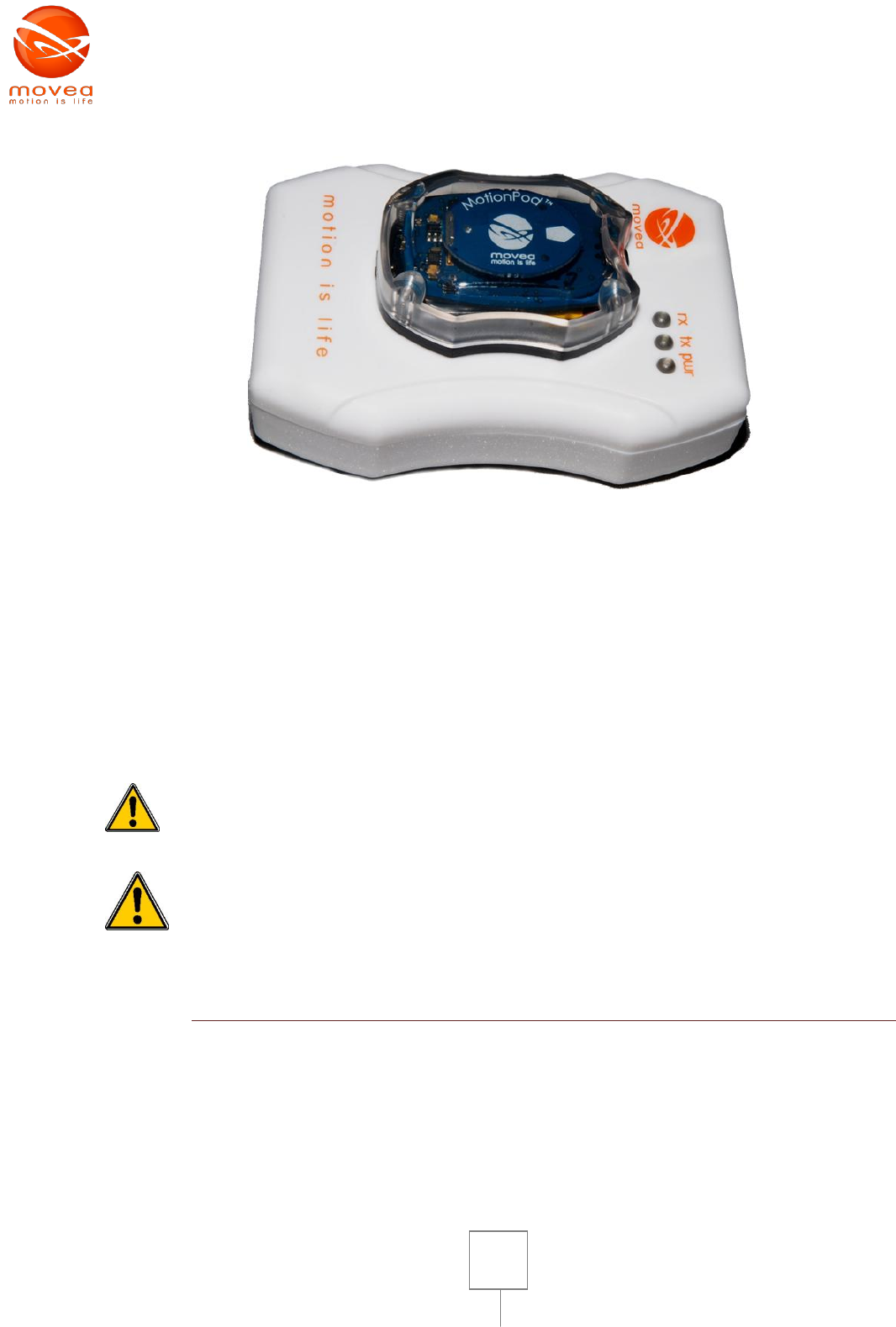
system is suitably locked and started charging (if charging is needed). The whole unit must look like
the photograph on Figure 5.
The MOTIONPOD™ encloses a battery. Battery performance gradually decreases
over an extended period of time (see the number of possible charging cycles). In
case of extended period of no use, it is advised to check the battery condition by
charging it. If the battery does not charge any more it is necessary to return the
product to the manufacturer for maintenance (battery exchange). This
operation cannot be carried out by the user. Opening of MOTIONPOD™ (or
MOTIONCONTROLLER™) will void the manufacturer warranty.
10
FIGURE 5 : THE MOTIONPOD™ FIXED ON THE MOTIONCONTROLLER™, READY FOR RECHARGE
While charging, an orange light indicator located at the back of the MOTIONPOD™ switches on. It
switches off as soon as the recharging process is complete. Theoretically, charging duration is 3
hours.
When the MOTIONPOD™ is recharged after a very long period of no use, it is possible that the
orange light indicator takes a few minutes before switching on.
If the battery reaches its critical point due to a long period of storage, the only solution is to return
the MOTIONPOD™ to your supplier for battery replacement (at own expense).
It is dangerous and strictly prohibited to use any other charging equipment than
the MOTIONCONTROLLER™ of Movea. Using other charger can damage the
MOTIONPOD™ and will void your manufacturer warranty.
The MOTIONPOD™ should not be opened. The battery replacement should be
carried out by your supplier.
2. HOW TO SWITCH THE MOTIONPOD ON AND OFF
The MOTIONCONTROLLER™ must be connected to the PC. The MOTIONPOD™ must formerly be
recharged. Take the MOTIONPOD™ off the MOTIONCONTROLLER™.
Slightly push the button on the MOTIONPOD™ to switch it on. At this stage, the green light indicator
blinks with a 5 second interval. The MOTIONPOD™ is not in transmitting any data to the
MOTIONCONTROLLER™ at this stage, it is simply on standby. You can switch the MOTIONPOD™ off
by a pressing on the button for 4 seconds. The green light indicator blinks twice before switching off
11
for 3 seconds. It then switches on for 1 second. As soon as the indicator emits a continuous light, you
can release the button.
The provided software will guide you through an effective data transmission between the
MOTIONPOD™ sensor and the MOTIONCONTROLLER™.
3. HOW TO WEAR THE MOTIONPOD™
To fix MOTIONPOD™ on the patient, use solutions provided by the product supplier. Be sure not to
tighten up excessively. The MOTIONPOD™ is provided with a mechanical interface to attach
bracelets, belts or straps. This is the only interface that the user must use to adapt non-magnetic
bracelets provided by the manufacturer. The MOTIONPOD™ should not be in contact with any other
material that can cause measurement distortion.
MOTIONPOD™ must however remain attached to the patient. A biocompatible Clothing interface can
be placed between the skin and the MOTIONPOD™ to guarantee hygiene and to avoid direct contact.
Do not use any other mechanical interface than the one provided by the supplier and specially made
for this purpose.
VII. PRECAUTIONS
1. USING ENVIRONMENTS
The MOTIONPOD™ is a measurement technology based on accelerometers and magnetometers. Its
main function is to provide the user with 3D orientation of the body segment wearing the sensor.
The MOTIONPOD™ is well-adapted to estimate posture of a joint segment. Measurements must be
carried out in static or quasi-static position.
The use of MOTIONPOD™ does not consist of any delayed or long-lasting response. Movements of
the patient must however be carried out under control of health professional. Indications given by
the MOTIONPOD™ are not facts.
The MOTIONPOD™ encloses sensors that to measure orientation parameters in space. These
measurements should not be used for diagnosis. They are only informative and meant to support
the physical therapists decision. They are not certified, so the information they give must be subject
to discussion.
Like any electronic device, there is a risk of modification of the systems’ essential
performances in case of electromagnetic disturbances. This risk is increased by
the presence of magnetometers in the system.
Note 1: A magnetic object is disturbing. Similarly, a ferrous object (attractable by a magnet)
is also very likely to disturb magnetometers of the MOTIONPOD™.

12
Note 2: A mobile phone often has a loudspeaker which contains magnets itself.
For best performances of your system, you must respect conditions of use and rightfully choose the
site where you carry out measurements:
- You must carry out sessions of measures at a usual chosen place, where magnetic
disturbances are minimal.
- When various postures or positions are carried out by the subject, it is necessary to avoid
translations higher than 1m of amplitude. The static magnetic field must be constant and
uniform inside the area of work.
- Keep any ferrous objects far from measurement site (approximately at a distance twice the
largest dimension of the ferrous object) ; for example :
o Scissors : 30 cm
o Laptop battery : 50 cm
o Keys : 15 cm
o While using the MOTIONPOD™ for measurement or calibration (see further below),
see to it that there isn’t any object likely to disturb measurements (ferrous objects,
watches, mobile phone…)
o MOTIONPOD™ should be used far from motorized chairs or beds.
o Only small magnets are accepted in the same room (i.e. whiteboard magnet), but
must be kept far from the MOTIONPOD™ (>50 cm), as they might cause a serious
decrease in the systems accuracy.
o DO NOT TO PUT THE MOTIONPOD™ IN CONTACT WITH A MAGNET AS IT WILL
MAKE IT PERMANANTLY USELESS.
o The presence of strong magnetic field generating machines (like MRI) is not adapted
to the use of MOTIONPOD™.
13
2. CHARACTERISTICS AND ENVIRONMENTAL CONDITIONS
Usage conditions
Temperature
Stable between 0°C and 45°C
Maximum dynamic acceleration measured
-6g à 6g
orientation measures are valid for static and quasi static positions
The measured orientation parameter is valid in a uniform or quasi uniform magnetic field between -6
gauss and +6 gauss1
Shock resistance
4600 g for a time of 0,5 ms
MOTIONPOD™ should not be thrown away
violently. It is however resistant to shocks
for normal conditions of use.
Magnetic field survivability
10 000 Gauss
Maximum rate of magnetic field tolerated before miss-
calibration
20 Gauss
Packaging and transport conditions
Temperature
Between -20°C and 45°C (For 1 month
maximum)
Shock resistance
4600 g for a time of 0,5 ms
Magnetic field survivability
10 000 Gauss
Maximum rate of magnetic field tolerated before miss-
calibration
20 Gauss
Storage conditions
Temperature
Between -20°C à 35°C (For 6months
maximum)
45°C (For 1 month maximum)
Shock resistance
4600 g for a time of 0,5 ms
Magnetic field survivability
10 000 Gauss
Maximum rate of magnetic field tolerated before miss-
calibration
20 Gauss
MOTIONPOD™ transmits data to the MOTIONCONTROLLER™ via radio signal. The
transmitted signal is a Bluetooth band. MOTIONPOD™ is tested in CEM. However,
band obstruction caused by the presence of other radio operating devices can lead
to interferences with MOTIONPOD™. Do not to use the MOTIONPOD™ when other
radio operating devices are running and are priority for patients.
1 MotionDevTool v2.0.4 software automatically checks if this condition is verified during recording of the
movement signature. An alarm is emitted in case of magnetic disturbance. If there is no alarm, the user is
under desired conditions.
14
VIII. CALIBRATION
When to calibrate?
Your MOTIONPOD™ has been calibrated during the manufacturing. Calibration consists in adjusting
certain parameters for offset and to obtain standardized measurements. However, over a long
period of time, or after a magnetic shock, the sensors are likely to drift. It is then necessary to
calibrate.
Depending on the software solution you have purchased, there is a measurement stability indicator
for angular data recording. Irregularity on accelerometer measures can be due to a very fast
movement. The software will probably request re-recording with a slower gesture. If
magnetometers are responsible for the anomaly, it is more likely because there are magnetic
disturbances in the environment. In all other cases, it is necessary to calibrate.
It is recommended to calibrate MOTIONPOD™ manually before any procedure. Calibration lasts 30
seconds and it is well guided by the provided MotionDevTool v2.0.4 Software. It mainly performs
measurements, and has menus to calibrate the MOTIONPOD™ according to the procedure described
below.
How to calibrate?
Here’s the best way to calibrate the MOD:
- Be sure that the zone where the calibration is carried out is free from any magnetic
disturbance (refer to section VII).
- Take the sensor in hand, put your elbows on a wooden table and maintain the
MOTIONPOD™ with your fingers.
- It is advised to have your face oriented north
- Rotate the MOTIONPOD™ with your fingers according to 3 axes of rotation:
o around the arrow figuring on the antenna
o around an axis perpendicular to this arrow
o around an axis perpendicular to the antenna (the MOTIONPOD™ “rolls” like a wheel)
o other additional random rotations can be made
Be sure to maintain the MOTIONPOD™ in the same position, in a sphere of 5cm of
diameter. Carry out slow movements without acceleration, nor shock
15
IX. CLEANING
1. CLEANING THE MOTIONCONTROLLER™
The MOTIONCONTROLLER™ is made of ABS plastic. Frequent disinfection or cleaning is not needed
because it’s not in contact with the patient.
Disconnect the MOTIONCONTROLLER™ before cleaning. Use a soft and dry napkin.
2. CLEANING THE MOTIONPOD™
MOTIONPOD™ and the mechanical interface are made of natural polycarbonate (for the transparent
cover) and of “Glass polycarbonate “” (the Black bottom cover, and mechanical interface). The
button on MOTIONPOD™ is in NBR. For cleaning or disinfection, use products listed below or other
products compatible with these materials. Cleaning products must be compatible with
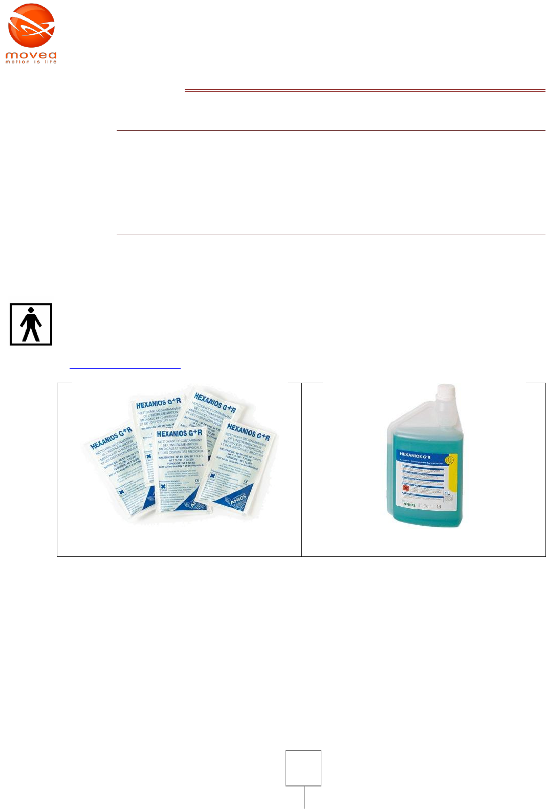
Polycarbonate. Do not immerse the MOTIONPOD™ in these products. Use a wet paper.
Example of well adapted cleaning products: HEXANIOS G+R from Anios laboratories
(http://www.anios.com)
Wet cleaning napkins
Liquid container
FIGURE 6 : WELL ADAPTED DISINFECTION PRODUCTS HEXANIOS G+R
16
X. SIGNS AND LABELS
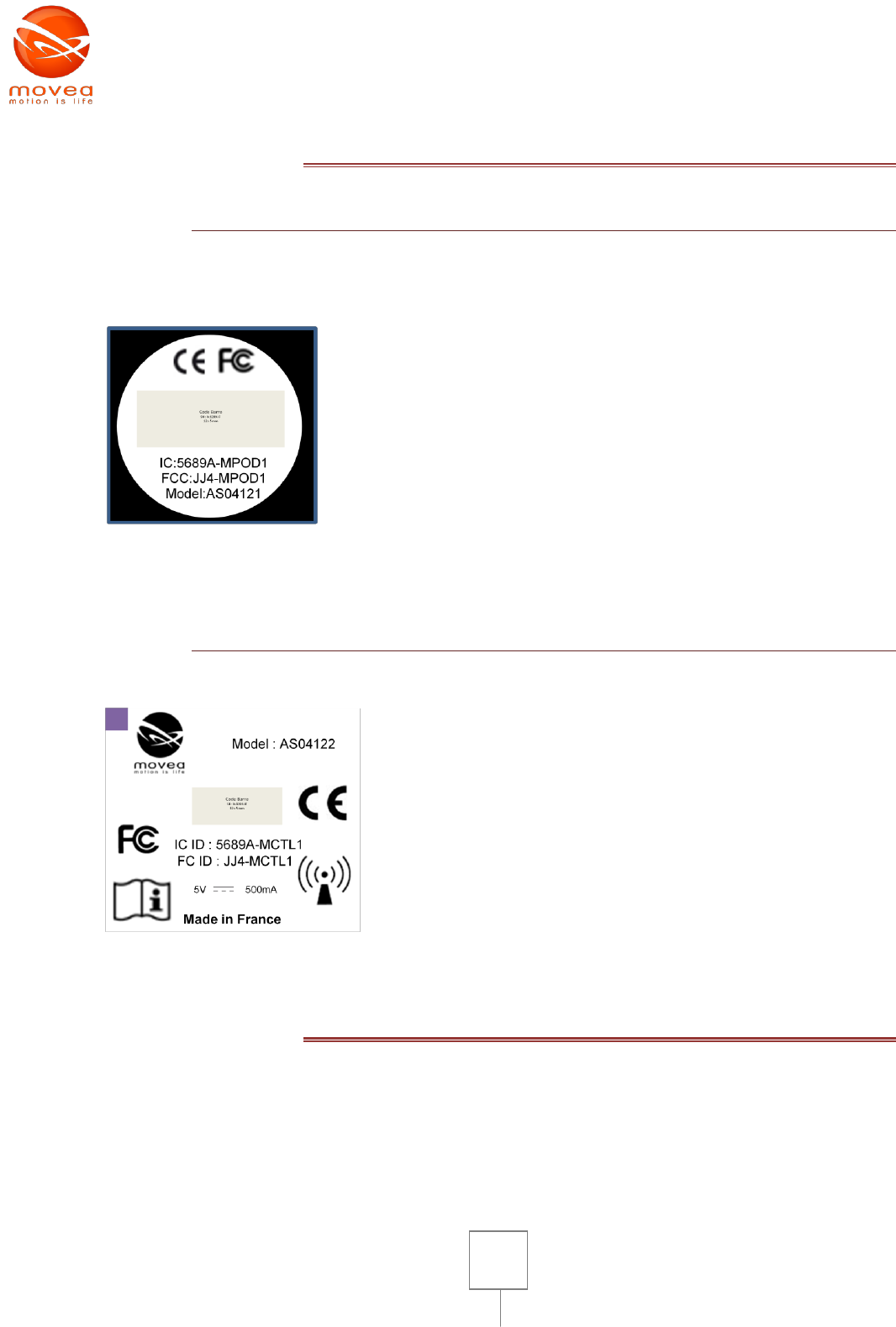
1. THE MOTIONPOD™
The MotionPod is the part of the system in contact with the subject.
Label of the MOTIONPOD™ (on the Black bottom cover)
15 mm of diameter
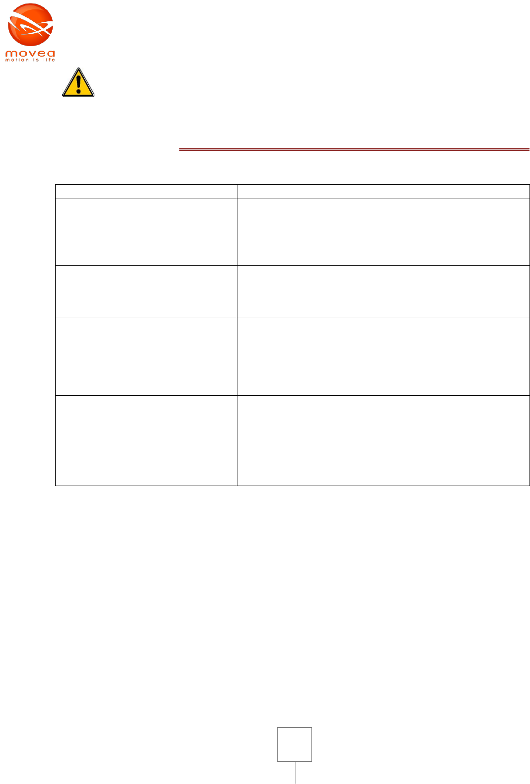
2. THE MOTIONCONTROLLER™
The label of the MOTIONCONTROLLER™ figures at the bottom of the case
Dimension~ 30 x 33 mm
XI. MAINTENANCE
The MOTIONPOD™ system does not require any particular maintenance other than cleaning after
each use. Manufacturer calibration is carried out at the time of manufacture of the MOTIONPOD™.
Follow instructions on section VIII for re-calibration.
The MOTIONPOD™ should not be opened. Battery replacement operation should
only be carried out by supplier’s qualified personnel.
17
XII. WHAT TO DO IN CASE OF SYSTEM BREAKDOWN
Symptoms
Possible solutions
The application doesn’t recognize
the MOTIONCONTROLLER™
- Make sure that the software has been installed
properly
- Close the software, unplug and re-plug the
MOTIONCONTROLLER™ and rerun the software
- If the problem persists contact your local distributor
The MOTIONCONTROLLER™
doesn’t work properly, the green
light indicator doesn’t go n when
plugged on PC
- Make sure that the PC is on and working
- Changer the USB cable
- If problem persists, contact your local provider
The MOTIONPOD™ green light
indicator doesn’t go on when
pushing the button
- Make sure that the battery is not empty, for that
place it on the MOTIONCONTROLLER™. The
MOTIONCONTROLLER™ must be plugged on a
running PC. The orange light indicator goes on to
show the start of recharging process.
- If problem persists, contact your local provider.
There has been a power cut-off and
the MOTIONCONTROLLER™ lost
connection with the PC, the
software lost all contact with his
reception peripheral. It could be an
unfortunate disconnection of the
MOTIONCONTROLLER™.
- Close the software,
- Unplug and re-plug the MOTIONCONTROLLER™ and
- Rerun the software
The MOTIONPOD™ system doesn’t need any particular maintenance (other than cleaning)
Company address:
MOVEA, MINATEC
7 Parvis Louis Neel
38040 Grenoble Cedex
Support: +33 438023721

18
Regulatory Information
Notice to Users:
This equipment has been tested and found to comply with the limits for Class B digital device, pursuant to Part 15 of the FCC rules.
These limits are designed to provide reasonable protection against harmful interference in a residential installation. This equipment
generates, uses and can radiate radio frequency energy and, if not installed and used in accordance with the instructions, may cause
harmful interference to radio communications. However, there is no guarantee that interference will not occur in a particular
installation. If the equipment does cause harmful interference to radio or television reception, which can be determined by turning the
equipment off and on, the user is encouraged to try to correct the interference by one or more of the following measures:
• Reorient or relocate the receiving antenna.
• Increase the separation between the equipment and the receiver.
• Plug the equipment into an outlet on a circuit different from that which the receiver is plugged.
• Consult the dealer or an experienced radio/TC technician for help. This product works using a radio frequency, so use on an
airplane may be restricted due to interference.
FCC Statement:
This device complies with part 15 of the FCC Rules. Operation is subject to the following two conditions: (1) This device may not
cause harmful interference, and (2) this device must accept any interference received, including interference that may cause
undesired operation. Changes or modifications not expressly approved by the party responsible for compliance could void the user's
authority to operate the equipment. The antenna(s) used for this transmitter must not be co-located or operating in conjunction with
any other antenna or transmitter.
CE
This equipment has been tested and found to comply with the limits of the European Council Directive on the approximation of the
law of the member states relating to electromagnetic compatibility (89/336/EEC) according to EN 55022 Class B.
Industry Canada Equipment Notice the Industry Canada certification identifies certified equipment. This certification means that the
equipment meets certain telecommunications network protective, operational and safety requirements as prescribed in the
appropriate Terminal Equipment Technical Document( s). The Department does not guarantee the equipment will operate to the
user's satisfaction. Before installing this equipment, users should ensure that it is permissible to be connected to the facilities of the
local telecommunications company. The equipment must also be installed using an acceptable method of connection. The customer
should be aware that compliance with the above conditions may not prevent degradation o f service in some situations. Repairs to
certified equipment should be coordinated by a representative designated by the supplier. Any repairs or alterations made by the
user to this equipment, or equipment malfunctions, may give the telecommunications company cause to request the user to
19
Copyright © 2008-2009 Movea. All rights reserved
EN-2008
MotionPod™
Users’ Guide

20
disconnect the equipment. Users should ensure, for their own protection, that the electrical ground connectors of the power utility,
telephone lines and internal metallic water pipe system, if present, are connected together. This presentation may be particularly
important in rural areas.
Caution: Users should not attempt to make such connections themselves, but should contact the appropriate electric inspection
authority or electrician, as appropriate.