Movea TT2 Transceiver User Manual DE02559 001 Rev 1A CCS copy
Movea, Inc Transceiver DE02559 001 Rev 1A CCS copy
Movea >
Contents
- 1. Users Manual
- 2. User manual regulatory statement
Users Manual

Gyration, Inc.
Page 1 of 1
DE02559-001
Revision 1.0A DRAFT
Product Specification
RF-only Transceiver Dongle
(in GyroTransport plastic)

Gyration, Inc.
Page 2 of 2
Table of Contents
DE02559-001..................................................................................................................................................1
REVISION 1.0 DRAFT ...............................................................................................................................1
PRODUCT SPECIFICATION ...................................................................................................................1
RF-ONLY TRANSCEIVER DONGLE .....................................................................................................1
(IN GYROTRANSPORT PLASTIC) ........................................................................................................1
1 INTRODUCTION ...............................................................................................................................4
1.1 REFERENCED DOCUMENTS .................................................................................................................4
2 TRANSCEIVER EXTERNAL CONTROLS AND DISPLAYS ....................................................5
2.1 “CONNECT” (MOMENTARY PUSH BUTTON).......................................................................................5
2.2 “STATUS” (LED, ORANGE).................................................................................................................5
3 PHYSICAL / MECHANICAL............................................................................................................5
3.1 EXTERNAL DIMENSIONS – PCB ASSY....................................... ERROR! BOOKMARK NOT DEFINED.
3.2 EXTERNAL – PLASTIC ASSEMBLY ........................................................................................................5
3.3 EXTERNAL – PLASTIC ASSEMBLY – COLOR DEFINITION......................................................................5
4 FUNCTIONALITY - TRANSCEIVER .............................................................................................6
4.1 USB COMPATIBILITY...........................................................................................................................6
4.1.1 USB Wake from S3 State ......................................................................................................6
4.2 USB ENUMERATION ...........................................................................................................................6
4.3 FUNCTIONAL BEHAVIOR SPECIFICATIONS:........................................................................................6
4.4 CONNECTIVITY....................................................................................................................................6
4.4.1 Proximity Binding.................................................................................................................6
4.5 MULTIPLE TRANSCEIVERS IN A SYSTEM ..............................................................................................7
4.6 COMPATIBILITY MATRIX WITH GYRATION PRODUCTS .......................................................................7
5 WINDOWS MEDIA PLAYER SOFTWARE SERVICE APPLICATION...................................8
6 SPECIFICATIONS ..............................................................................................................................9
6.1 MATERIAL ...........................................................................................................................................9
6.2 LABELS AND GRAPHICS ......................................................................................................................9
6.3 ACTUATION LIFE SPECIFICATION.......................................................................................................9
6.4 ABSOLUTE MINIMUM/MAXIMUM PARAMETERS ............................................................................10
6.5 OPERATING VOLTAGE ......................................................................................................................10

Gyration, Inc.
Page 3 of 3
6.6 CURRENT CONSUMPTION.................................................................................................................10
6.7 RADIO FREQUENCY SPECIFICATIONS ...............................................................................................10
7 ENVIRONMENTAL RATINGS AND RELIABILITY TEST ....................................................11
7.1 ENVIRONMENTAL PARAMETERS ......................................................................................................11
7.2 RELIABILITY TEST CRITERIA [A] .......................................................................................................11
7.3 ELECTROSTATIC DISCHARGE (ESD) REQUIREMENTS ......................................................................11
8 COMPLIANCE...................................................................................................................................12
9 TESTING.............................................................................................................................................12
9.1 QUALIFICATION / RELIABILITY TESTING .........................................................................................12
9.2 PRODUCTION TESTING......................................................................................................................12
9.3 LOT SAMPLING TESTING...................................................................................................................12
10 PACKAGING REQUIREMENTS...............................................................................................13
10.1 BULK PACKAGING REQUIREMENT....................................................................................................13
10.2 BULK PACKAGING QUALIFICATION TESTING ..................................................................................13
11 REVISION HISTORY...................................................................................................................14
Gyration, Inc.
Page 4 of 4
1 Introduction
This document is the specification for the RF-only Transceiver dongle, built in
GyroTransport plastic. This design is based off of the hardware design of the Gyration
“Gen II” receiver but is placed in the small form factor of the GyroTransport transceiver.
Some components changed from the Gen II design (smaller IC package) to allow the
design to shrink in size. This transceiver design is intended to be used with (but is not
limited to) the MusicLCD remote.
1.1 Referenced Documents
TBD
Gyration, Inc.
Page 5 of 5
2 Transceiver External Controls and Displays
2.1 “Connect” (momentary push button)
For engineering use only; not installed for production.
2.2 “Status” (LED, orange)
The LED indicates when there is radio traffic on this device.
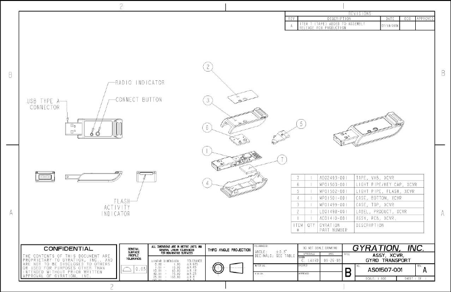
3 Physical / Mechanical External – Plastic assembly
For reference only – mechanical drawing shown is for GyroTransport with Flash assembly
3.1 External – Plastic assembly – color definition
TBD
Gyration, Inc.
Page 6 of 6
4 Functionality - Transceiver
4.1 USB Compatibility
The transceiver uses a standard USB Type A connector for connection to any standard
USB port of a computer. The transceiver is a certified USB compatible 2.0 device, running
at low speed. It is certified to run on Windows XP and XP Media Center operating
systems. Vista-Compliance is TBD (as of August 31, 2006)
4.1.1 USB Wake from S3 State
When the host system has been configured to wake from the S3 state (Standby) from
external device activity, the transceiver will produce a standard USB wake pulse (10 ms)
on the D- data line upon reception of valid radio traffic (radio transmissions from bound
units). This will wake the host system from Standby.
4.2 USB Enumeration
When the transceiver is plugged into the host system, it will be recognized and
enumerated as a composite device; mouse and keyboard.
The Product ID code (PID) of this device is (TBD).
4.3 Functional Behavior Specifications:
The functional behavior of this product is completely specified in the following table:
The transceiver is a USB 2.0 device that enumerates as follows:
I. Composite device with:
a. HID mouse - interrupt type at 10 ms intervals interfaced to
i. Generic desktop page (01)
ii. Consumer page (0C)
iii. Media Center page (FFBC)
b. HID keyboard - interrupt type at 10 ms intervals interfaced to
i. Generic desktop page (01)
ii. Consumer page (0C)
4.4 Connectivity
4.4.1 Proximity Binding
The transceiver has a unique feature which allows it to automatically bind with a
compatible device in close proximity, thereby avoiding the need to press a “connect”
button on the actual transceiver. This feature enables users to pair devices by simply
holding them close together. This proximity binding distance is approx 12 inches +/-
6 inches and could be fully adjustable in firmware for any application. The actual
distance may vary based on the user’s position relative to the computer.
The transceiver also has the capability to bind using the standard Gyration “connect”
button method where a connect button on each of the connecting devices is pressed
to initiate and complete a bind sequence. (the firmware in the transceiver has both
algorithms).

Gyration, Inc.
Page 7 of 7
The physical plastic contains a hole for a connect button but can be covered with a
product label if a proximity bind configuration is desired, thus saving the need for
different plastic parts based on the bind algorithm chosen.
4.5 Multiple transceivers in a system
When multiple transceivers are installed by plugging them into different USB slots of the
same computer, the following operation is noticed.
When both transceivers are proximity-bind transceivers:
When a proximity bind is attempted by moving 1 “proximity-bind enabled controller”
(like a remote control) close to the computer, that controller may bind to any of the
transceivers. The proximity bind algorithm relies on the controller and transceiver to be in
close proximity and a bind process would be started with the closest combination at that
time, and maybe wont be the pair desired. To prevent this, only 1 proximity-bind receiver
should be installed in the computer at a time while doing the bind sequence.
When in a Dell XPS2010 system (Greenland with an internal daughter card)
TBD
4.6 Compatibility matrix with Gyration products
This is a matrix that describes the compatibility of this proximity-bind RF-only transceiver
with all other Gyration products.
TBD
Gyration Go Mouse
Gyration Go Mobile keyboard
Gyration Go Full size keyboard
Gyration Media Center Universal Remote Control
Gyration GyroTransport
Gyration GyroTools software application
Dell MusicLCD Remote (RMT5)
Dell internal daughter card (Orc)
Gyration, Inc.
Page 8 of 8
5 Windows Media Player Software Service Application
The Windows Media Player (WMP) software service application is an add-on user
installed program that interfaces in the background to the Windows Media Player
(version 10 or greater). This service application transfers music metadata information to
the transceiver. This feature is extra on the transceiver and does not interfere with the
standard USB operation of the transceiver. The transceiver would take that information
and send it via the Gyration RF link to the attached MusicLCD remote and then would be
displayed on the LCD screen of the remote. This information is only intended for the
Gyration / Dell products that support the Music LCD.
The service application has the following features / limitations:
- limited to only the Windows Media Center Operating system.
- Installs into a default directory unless selected differently during installation
- During installation, has a selection for multiple languages
- Is supplied on a mini-CD or a downloadable application
- Full HTML-based help (TBD)

Gyration, Inc.
Page 9 of 9
-
6 Specifications
6.1 Material
The following materials are to be used for the product:
Part(s) Material Color
Printed circuit board (PCB) FR4 Green
6.2 Labels and Graphics
The following labels and graphics shall be applied to the product:
Name of
Label or
Graphic
Material of
Label or
Graphic
Placement Example
External
graphics
silkscreen
External
product
label
Label
6.3 Actuation Life Specification
The product should still function correctly after the following number of cycles of each of
the following:
Description Symbol Min Nom Max Units
Number of times the transceiver can be
removed and inserted without
degradation of electrical reliability.
Standard USB Type A connector
TBD cycles

Gyration, Inc.
Page 10 of 10
6.4 Absolute Minimum/Maximum Parameters
Description Symbol Min Nom Max Units
Supply Voltage +5.0V - Volts
6.5 Operating Voltage
Description Symbol Min Nom Max Units
Supply Voltage +5.0V Volts
6.6 Current Consumption
Description Symbol Min Nom Max Units
Operating Current Consumption:
product functioning normally, but
all LED’s off (Supply V = 5.0V)
I_Oper - mA
Standby Current Consumption (when
USB bus goes inactive) (Supply V = 5.0V)
I_Standby - mA
Current prior to enumeration (Supply V
= 5.0V)
I_Prior - mA
6.7 Radio Frequency Specifications
The radio transceiver operates in the unlicensed Industrial, Scientific, and Medical (ISM)
band.
• Frequency band: 2.4 GHz to 2.483 GHz
• Modulation type: Direct Sequence Spread Spectrum (DSSS)
• Maximum transmitted power: 0 dBm
• FCC emitter designator: 866KF1D
• Data code type: Pseudo Noise (PN) Code
• Antenna Type: integrated printed trace wiggle

Gyration, Inc.
Page 11 of 11
7 Environmental Ratings and Reliability Test
7.1 Environmental Parameters
SYM PARAMETER MIN TYP MAX UNITS
Toper Operating Temp 0 25 85 °C
Tstore Storage Temp -40 - 70 °C
Hrel Relative Humidity (non-
condensing) @ 60°C
10 - 90 Percent
Ss Shock Survivability 75 - - cm
Alt_op Altitude, Operating 0 - 3,000 m
Alt_st Altitude, Storage 0 - 12,000 m
The unit should not be subjected to direct sunlight for extended periods of time.
7.2 Reliability Test Criteria [A]
# PARAMETER MIN Reference
A1 Appearance & Size Any conspicuous deformation, crack, loose joint is not
allowed.
A2 Functional Test over
Voltage Range
Unit must be functional over the voltage range:
Operating Voltage 6.5
A4 Standby Current Must meet I Standby 5.6
A5 RF Frequency Must meet RF frequency specification 6.7
7.3 Electrostatic Discharge (ESD) Requirements
The transceiver will be tested at the system level to the CE testing specifications.

Gyration, Inc.
Page 12 of 12
8 Compliance
The transceiver will comply with the following agencies and standards:
Agency or Standard Reference
FCC (US) 15.247 (2400-2483.5)
IC (Canada) RSS-210
CE (European Community) EN 301 489-17 Emissions & Immunity
EN 300 328 wireless testing
EN 60950 Safety
RoHS Will be independently verified
OTHER STANDARDS TO BE DETERMINED AT A LATER TIME
Telec (Japan) Japan Wireless Device
Australia / New Zealand EMC
Singapore Singapore Approval
9 Testing
9.1 Qualification / Reliability Testing
Any changes in design or selection of parts or component, or new design release, will
require a qualification test with units built using finished (tooled) parts prior to placing in
production. Tests will confirm that product will conform to performance and reliability
requirements outlined in this specification. Minimum sample size is 10 units.
Manufacturer must provide report of qualification /reliability test to Gyration.
9.2 Production Testing
Each unit is to be tested during the build process according to the applicable specification,
approved by Gyration. Only units that conform to this document are shippable product.
9.3 Lot Sampling Testing
Lot sampling testing must be performed at the manufacturer according to the applicable
specification, approved by Gyration, prior to shipment. Lot Sampling Testing will form
the basis for acceptance or rejection of production lots.
Gyration, Inc.
Page 13 of 13
10 Packaging Requirements
10.1 Bulk Packaging Requirement
Manufacturer must propose design of bulk packaging for product. Design of bulk
packaging must be approved by Gyration, and must pass 10.2 - Bulk Packaging
Qualification Testing.
10.2 Bulk Packaging Qualification Testing
The design for Bulk Packaging Cartons should be qualified by the manufacturer by the
following method: Each carton should be subjected to a six side/four corner drop test (1
meter) with no product damage. Manufacturer must provide report of qualification test
to Gyration.
Cartons will be designed to withstand normal banding or strapping without damage
when a band or strap is positioned at the midpoint of a longest edge. Minimum sample
size for Bulk Packaging Testing is 5 cartons.
Bulk packaging diagram to be placed here

Gyration, Inc.
Page 14 of 14
11 Revision History
Rev Date Description Initials
1.0 0/28/06 Initial draft BKL
1.0A 09/14/06 Initial draft – Special for CCS GRD