Movita Technologies H300 Notebook Computer User Manual 330 index US
Movita Technologies Inc. Notebook Computer 330 index US
User Manual
Table Of Contents
Chapter 1
:
Introduction ………………………………….. ……..1-1
Welcome…………………………….……………………………………..………1-1
To Open the Notebook. …………….. …………………………………….. ……..1-1
Taking a look at this Notebook …………………………………………….……..1-2
Front View …………………………………………………………………………1-2
Left View…………………………………..……………………………………...1-3
Right View……………………………………….. ……………………………….1-4
Rear View…………………………………………….. ………………………….1-4
Bottom View ……………………………………………….. …………………….1-5
Chapter 2
:
Operating The Notebook ………………………….2-1
Getting the Computer Running………………………….. ………………………2-1
Connecting Power to the System………………………………………………2-1
Turning On and Off the Computer…………………………….. ………………2-2
About Power Indicators …………………….. …………………………………….2-3
About the Status Indicators…………………….. ………………………………..2-3
About the Keyboard………………………………………………………………..2-4
Using the Touch pad………………………….. ………………………………….2-5
About a Security Lock (Kensington Lock)……………………………………….2-5
Using the Video Features …………………………………………………………2-5
Settings…………………………………………………………..………………..2-5
Setting the External Monitor ………………….…………………………………2-6
Using the Audio Features …………………………….. ………………………….2-6
Sound Ports………………………………………………….. …………………..2-6
Using the Communication Features ………………………….………………….2-7
Using the LAN………………………………………….…………………………2-7
Using the Modem …………………………………………….…………………..2-7
Using the Optical Drive……………………………………………………………2-8
Connecting the external optical Drive……………………….…………………2-8
Inserting and removing a CD……………………………………………………2-8
Using the Floppy Disk Drive ……………………….……………………………..2-9
Using the Hard Disk Drive………………………………..……………………….2-9
Using the Utility CD………………………………………….. ………………….2-10
Chapter 3
:
Power Management ………………………………..3-1
About the AC Adapter …………………………………….……………………….3-1
Using the Battery Pack……………………………………………………………3-2
To Change the Battery Pack …………………………………..……………….3-2
Battery Charging………………………………………………………………….3-2
Battery Discharging………………………………………………………………3-2
Battery Low Warnings……………………………………………………………3-3
Using Power Management…………………………….………………………….3-3
Standby Mode …………………………………………………………………….3-3
Hibernate Mode…………………………….…………………………………….3-3
Initiating Standby or Hibernate Mode…………….…………………………….3-4
Chapter 5: Expanding The Notebook…………….……………5-1
Using PC Cards……………………………….. ………………………………….5-1
PC Card Type……………………………………….. …………………………..5-1
CardBus Support …………………………………………………………………5-1
Inserting and Removing a PC Card …………………………………………….5-1
Connecting a USB 2.0 Device……………………………………………………5-3
Connecting an External Monitor ………………………………………………….5-3
Internal Components Upgrade………………………………….………………..5-4

Notice: The changes
or modifications not expressly approved by the party responsible for
compliance could void the user’s authority to operate the equipment.
Federal Communications Commission (FCC) - Notebook
The Federal Communication Commission Radio Frequency
Interference Statement includes the following paragraph:
This equipment has been tested and found to comply with the limits for
a Class B digital device, pursuant to Part 15 of the FCC Rules. These
limits are designed to provide reasonable protection against harmful
interference in a residential installation. This equipment generates,
uses, and can radiate radio frequency energy and, if not installed and
used in accordance with the instructions, may cause harmful
interference to radio communications. However there is no guarantee
that interference will not occur in a particular installation. If this
equipment does cause harmful interference to radio or television
reception, which can be determined by turning the equipment off and
on, the user is encouraged to try to correct the interference by one or
more of the following measures:
q Reorient or relocate the receiving antenna.
q Increase the separation between the equipment and the receiver.
q Connect the equipment into an outlet on a circuit different from that
to which the receiver is connected.
q Consult the dealer or an experienced radio/TV technician for help.
Shielded interconnect cables and shielded AC power cable must be
employed with this equipment to insure compliance with the pertinent
RF emission limits governing this device. Changes or modifications not
expressly approved by the system’s manufacturer could void the user’s
authority to operate the equipment.
SAFETY & COMPLIANCE

Declaration of Conformity
This device complies with part 15 of the FCC rules. Operation is
subject to the following conditions:
q This device may not cause harmful interference.
q This device must accept any interference received, including
interference that may cause undesired operation.
Federal Communications Commission (FCC) – Fax/modem
This equipment complies with Part 68 of the FCC Rules. On this
equipment is a label that contains, among other information, the FCC
registration number and Ringer Equivalence Number (REN) for this
equipment. You must, upon request, provide this information to your
telephone company.
If your telephone equipment causes harm to the telephone network, the
Telephone Company may discontinue your service temporarily. If
possible, they will notify in advance. But, if advance notice isn't
practical, you will be notified as soon possible. You will be informed of
your right to file a complaint with the FCC.
Your telephone company may make changes in its facilities, equipment,
operations, or procedures that could affect proper operation of your
equipment. If they do, you will be notified in advance to give you an
opportunity to maintain uninterrupted telephone service.
The FCC prohibits connecting this equipment to party lines or coin-
telephone service.
In the event that this equipment should fail to operate properly,
disconnect the equipment from the phone line to determine if it is
causing the problem. If the problem is with the equipment, discontinue
use and contact your dealer or vendor.
The FCC also requires the transmitter of a FAX transmission be
properly identified (per FCC Rules Part 68, Sec. 68.381 (c) (3)).
Canadian Department of Communications-Notebook
This class B digital apparatus meets all requirements of the Canadian
Interference-causing Equipment Regulations.
Cet appareil numérique de la classe B respecte toutes les exigences
du Réglement sur le matériel brouilieur du Canada.
VCCI
DHHS- the CD-ROM Drive
FDA Regulations require the following statement for all laser-based
devices:
“Caution, Use of controls or adjustments or performance of
procedures other than those specified herein may result in
hazardous radiation exposure.”
Caution: This appliance contains a laser system and is classified as a
“CLASS 1 LASER PRODUCT”. To use this model properly, read the
instruction manual carefully and keep this manual for future reference.
In case of any trouble with this model, please contact your nearest
“Authorized Service Station”. To prevent direct exposure to the laser
beam, do not try to open this enclosure.
CLASS 1 LASER PRODUCT
LASERSCHUTZKLASSE 1 PRODUKT
TO EN60825

UL/TUV Battery & FAX/Modem Caution and Important
Safety Instructions
CAUTION
"CAUTION-To reduce the risk of fire, use only No.26 AWG or large
telecommunication line cord."
"CAUTION-Always disconnect all telephone lines from the wall outlet
before servicing or disassembling this equipment."
Danger of explosion if battery is incorrectly replaced.
Replace only with the same or equivalent type recommended by the
manufacturer. Discard used batteries according to the manufacturer’s
instructions.
VORSICHT!
Explosionsgefahr bei unsachgemäâen Austausch der Batterie Ersatz
nur durch denselben oder einem vom Hersteller empfohlenem
ähnlichen Typ. Entsorgung gebrauchter Batterien nach Angaben des
Herstellers.
IMPORTANT SAFETY INSTRUCTIONS
When using your telephone equipment, basic safety precautions should
always be followed to reduce the risk of fire, electric shock and injury to
persons, including the following:
Do not use this product near water, for example, near a bath tub, wash
bowl, kitchen sink or laundry tub, in a wet basement or near a
swimming pool.
Avoid using a telephone (other than a cordless type) during an
electrical storm. There may be a remote risk of electric shock from
lightning.
Do not use the telephone to report a gas leak in the vicinity of the leak.
Use only the power cord and batteries indicated in this manual. Do not
dispose of batteries in a fire. They may explode. Check with local
codes for possible special disposal instructions.
This product intended to be supplied by a Listed Power Unit,
marked ”Class 2” or “LPS” and output rated +15 ~ 16V dc , 3 ~ 3.13 A”
SAVE THESE INSTRUCTIONS

CTR21 Notice
The equipment has been approved in accordance with Council
Decision 98/482/EC for pan-European single terminal connection to the
public switched telephone network (PSTN). However, due to
differences between the individual PSTNs provided in different
countries, the approval does not, of itself, give an unconditional
assurance of successful operation on every PSTN network termination
point.
In the event of problems, you should contact your equipment
supplier in the first instance.
ANNEX II
Note: The manufacturer should ensure that the vendor and user of
the equipment is clearly informed of the above information by
means of packaging and/or user manuals or other forms of user
instructions.
ANNEX III
This declaration will indicate the networks with which the equipment
is designed to work and any notified networks with which the
equipment may have interworking difficulties.
Network compatibility declaration to be made by the manufacturer
to the user.
The manufacturer shall also associate a statement to make it clear
where network compatibility is dependent on physical and software
switch settings. It will also advise the user to contact the vendor if it
is desired to use the equipment on another network

CE Declaration of Conformity
The system computer model H300 and accessories conform to the
following production specifications:
Manufacturer Name:
Manufacturer Address:
Model Name: H300
Is herewith confirmed to comply with the requirements set out in the
Council Directive on the Approximation of the Laws of the Member
Sates relating to Electromagnetic Compatibility (89/336/EEC) and Low-
voltage Directive (73/23/EEC & 93/68/EEC). For the evaluation
regarding the Electromagnetic Compatibility and Low-voltage Directive
the following standards were applied.
Standards
89/336/EEC-EMC Directive
EN 55022:
1998/A1:2000(Clas
s B)
Limits and methods of measurement of radio
disturbance characteristics of information
technology equipment.
EN 61000-3-2 :
1995/A1/A2:1998/A
14:2000
Disturbances in supply systems caused by
household appliance and similar electrical
equipment “harmonics”.
EN 61000-3-3 :
1995/A1:1998 Part 2: harmonics/parts: voltage fluctuations.
EN 55024:1998 ITE Immunity Standard
IEC 61000-4-2 :
1995/A1:1998/A2:2
000
Electrostatic discharge requirements
IEC 61000-4-3 :
1996/A1:1998/A2:2
000
Immunity to radiated, radio frequency
electromagnetic fields
IEC 61000-4-4 :
1995/ A1:2000 Electrical fast transient requirements
IEC 61000-4-5 :
1995/ A1:2000
Surge requirements
1995/ A1:2000
IEC 61000-4-6 :
1996/ A1:2000 RF Common Mode requirements
IEC 61000-4-8 :
1993/ A1:2000 Power Frequency Magnetic Field requirements
IEC 61000-4-11 :
1994/ A1:2000 Voltage Interruptions and Voltage Dips
requirements
73/23/EEC-Low Voltage Directive
EN 60950 1992
+A1+A2+A3+A4+A
11
Safety for information technology equipment
including electrical business equipment
The following manufacturer/importer is responsible for this declaration:
Company Name:
Company Address:
Person responsible for making this declaration:
Name:
Position:
Place
Date:
1-1
Chapter 1
:
Introduction
Welcome
Thank you for purchasing this notebook computer.
The state-of-the-art computer is slim and ultra light, and possesses the
abilities of high powerful data computing and advanced 2/3D graphics
acceleration. It supports a variety of expansible function for expanding
memory, Hard disk and so on. Also, wherever you need it, the computer
is easy to go.
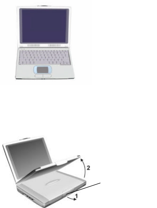
To Open the Notebook
Open the locking latch on the front edge of the notebook then lift the
screen up to a comfortable viewing angle.
Locking latch
1-2
Taking a look at this Notebook
This section describes the function of the notebook.
Note
:
Depending on the model of you purchased, the appearance of the
notebook may not exactly the same as those shown in this manual.
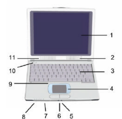
Front View
1. 10.4” LCD Screen
This computer supports 10.4” TFT LCD panel.
2. Right Speaker (P.2-6)
3. Keyboard (P.2-4)
4. Touch pad (P.2-5)
5. External Microphone Port
Connects an external microphone. (P.2-6)
6. External Audio Port
Connects external Audio devices, e.g. headphone, speaker, and so
on. (P.2-6)
7. Status Indicators
Indicating the operating status of this computer. (P.2-3)
1-3
8. Power Indicators
Indicating the power status of this computer. (P.2-3)
9. Internal Microphone (P.2-6)
10. Power Button
To turn the computer ON or OFF.
11. Left Speaker (P.2-6)
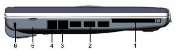
Left View
1. PC Card Slot
To load pc card for expanded functions. (P.5-1)
2. USB 2.0 Port
Connects the USB Devices. (P.5-3)
3. LAN Port
To connect LAN by RJ-45 LAN wire. (P.2-7)
4. Communication Port
To used Modem for telecommunication by RJ-11 phone line. (P.2-7)
5. External CRT Port
To presents display data to external display devices. (P.5-3)
6. Security Lock (Kensington Lock)
An anchor point for the locking mechanism on standard notebook
security cables. (P.2-5)
1-4
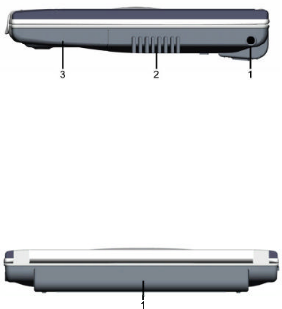
Right View
1. DC-IN Port
Connects the AC adapter. (P.2-1)
2. Airflow Vent Holes
Note
:
Please keep the vent holes well aired to prevent overheating of
the notebook.
3. Internal Hard Disk
This notebook computer allows one 2.5-inch IDE (Integrated Drive
Electronics) hard disk drive. (P.5-4)
Rear View
1. Battery Pack (Li-lon)
This notebook computer supports one rechargeable Li-lon battery. It
supplies power to the computer when external power is not
connected. (P.3-2)
1-5
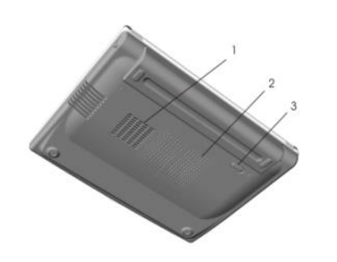
Bottom View
1. CPU Fan
The CPU fan to prevents overheating of CPU.
2. DDR RAM Cover
Inside is the DDR RAM slot for expanding the memory size of the
notebook computer. (P.5-4)
3. Battery Lock Latch
Please follow an arrow imprinted to lock or unlock internal battery.

2-1
Chapter 2
:
Operating The Notebook
This chapter provides information about the use of the notebook.
Getting the Computer Running
Connecting Power to the System
This notebook computer runs on its rechargeable battery. You can also
plug its AC adapter into a wall socket for continuous high-performance
operation or battery recharge. It is suggested that you use AC power
when you start up the computer for the very first time.
Warning
:
It is particularly important that you use only the AC adapter
supplied from your dealer in order to avoid damaging your notebook
computer.
To use the AC adapter, plug it into a wall socket, plug its DC cable into
your notebook's DC jack. This notebook computer's AC adapter has a
voltage sensor that accepts different countries' voltages without manual
adjustment.
1. Plug the power cord into a regular AC power supply outlet.
2. The power indicator on the AC adapter will turn on to show that it is
connected to AC power.
DC-IN
2-2
3. Plug the direct current cable from the AC adapter into the DC-IN port
on right side of the notebook.
4. The indicator on the front edge of the notebook will begin flashing
with a green light. This indicates that the AC adapter has begun
charging the internal battery.
Note: It is particularly important that you give your battery a full charge
the first time that you use it. We recommend that you leave the system
connected to the AC adapter until the battery is fully charged. The
battery charge indicator of the notebook will stop flashing when the
notebook is fully charged.
Turning On and Off the Computer
Turning On the Computer
1. Make sure the computer is connected to AC power.
2. Press the power switch of the computer.
3. Each time the computer is turned on; it performs a POST (Power-On
Self Test). When POST successfully completes its check, the
computer signals a single beep and the operating system such as
Windows should start.
Turning Off the Computer
In Microsoft Windows, you can shut down your computer by selecting
“Shut Down” within the Windows Start Menu. You can also restart your
computer from this menu.
Note: If the system is locked up because of hardware or software
problems, press the power switch to turn off the computer.
2-3
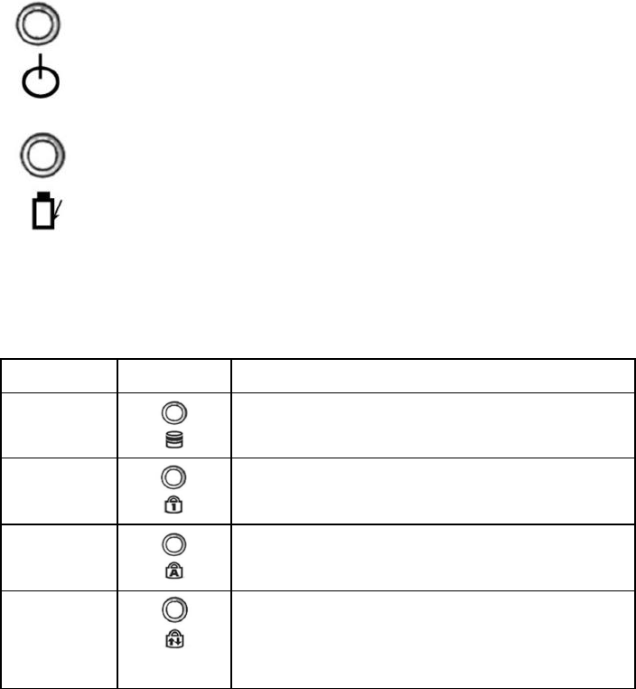
About Power Indicators
The two power indicators are located on the front edge of the notebook
base.
Power Indicator
Steady
:
System is ON
Flashing
:
System is suspended
Battery Charge Indicator
Steady
:
Battery is fully charged
Flashing
:
Battery is charging
About the Status Indicators
The four status indicators, from left to right, are:Hard Disk, Num Lock,
Caps Lock and Scroll Lock.
Indicator Icon Description (Light On)
Hard Disk
Write data to hard disk or read data from hard
disk.
Num Lock
The Num Lock activates the numeric keys.
Caps Lock
The Caps Lock keeps the letter keys in
uppercase.
Scroll Lock
The screen moves one line up or down when
you press ↑or↓
arrow key. Scroll Lock does
not work for all programs.
2-4
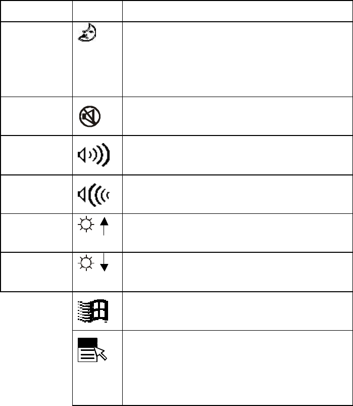
About the Keyboard
The exact layout of your keyboard depends on the language/system
you’re using. Displayed here is a standard US/Windows keyboard.
The table below shows the meaning of the function key icon, and other
embedded keyboard icons:
Keystrokes Icon Description
FN + F2 Serves as the sleep button that you can
define with Windows “Power Management”.
(See the “Using Power Management” in
Chapter 3)
FN + F6
This key combination turns off the volume of
the speakers.
FN + F7
This key combination increases the volume
of the speakers.
FN + F8
This key combination decreases the volume
of the speakers.
FN + F9
This key combination increases the
brightness of the built-in screen.
FN + F10
This key combination decreases the
brightness of the built-in screen.
This key activates the Start button Windows
Task Bar.
This key opens the pull down menu of a
selected icon or object. Its action is the same
as right-clicking an icon or object with a
mouse or Touchpad.
3-1
Chapter 3
:
Power Management
This chapter tells you how to use power management and delivers the
information about AC adapter, Internal battery pack.
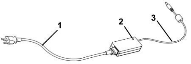
About the AC Adapter
The AC adapter serves as a converter from AC (Alternating Current) to
DC (Direct Current) power because your computer runs on DC power,
but an electrical outlet usually provides AC power.
The AC adapter is Auto-sensing so that your notebook can operate
through the AC adapter connected to any available power supply in a
wall outlet. The AC adapter is also used to recharge the rechargeable
battery pack when connected to AC power.
The AC adapter operates on any voltage in the range of 90~240V AC.
1. AC Power Cord
2. Power indicator light
3. DC (Direct Current) Cable
Warning
:
Connecting the AC adapter to other devices can damage the
adapter or devices. Because of this AC adapter is designed for use with
your notebook computer only.
3-2
Note
:
The AC power cord supplied with your notebook computer is for
use in the country where you purchased your notebook computer. If you
plan to go overseas with the notebook computer, consult your dealer for
the appropriate power cord.
Using the Battery Pack
The battery pack contains Lithium-Ion (Li-lon) that can be installed in the
rear side of the computer.
Warning
:
Only use the battery pack that is supplied with this notebook.
If you need a replacement battery, ask your system vendor for a
replacement. Never try to use a battery pack that is not designed and
approved for use in this notebook.
Note
:
Since batteries are consumables, the warranty will be ensured
within six months while you purchased.
To Change the Battery Pack
To change the battery, shut down the system, and turn your computer
over. Unlock and remove your battery, replace it with a charged battery.
Battery Charging
When the battery pack is installed in the rear side and the computer is
connected to a power supply with the AC adapter, the battery pack
automatically gets charged.
You can check on the charging status of the battery using the battery
charge indicator.
Battery Discharging
When your notebook is turned on and not connected to a power supply,
it will operate by discharging the battery. Battery life is reduced if your
notebook is consuming a lot of energy; for example playing sound files
and frequently accessing disk drives. Battery life will also be reduced if
your battery is not in good condition.
3-3
Battery Low Warnings
Your notebook will alert you to a low battery condition by emitting a
continuous beeping sound. This warning happens when the battery has
only 15% of total charge remaining.
If you continue using your computer after the battery low warning, the
notebook will continue to operate normally until the charge level drops
to around 5% of total charge. At this point, without warning, the
notebook will automatically turn off the system.
Using Power Management
This notebook supports ACPI (Advanced Configuration and Power
Interface) for power management. When you are running your notebook
from the internal battery, it is important that you use the power
management routines to reduce the system power consumption. They
routines consist of a series of power saving modes:standby mode, and
Hibernate mode.
Standby Mode
In a standby mode, the contents of your computer’s memory are held
intact, while practically all the rest of the components in your notebook
turn off completely, or reduce power consumption to a minimum. In a
standby mode, your computer remains active but with the minimum
possible power consumption. You can return the computer to full power
by pressing [Fn] + [F2].
Hibernate Mode
Hibernate mode is really another way of turning off your computer.
When you hibernate, the contents of your computer’s memory are
copied to your hard disk drive as a file. When the contents of the
memory have been safely stored to disk, your computer turns off. The
next time the computer is turned on after hibernate, the file on the hard
3-4
disk is quickly read back into memory. In just a few moments, your
computer appears exactly as it was when you last hibernate.
Hibernate is very useful for Windows users who like to have many
different programs open on the Windows desktop. You can take quite a
few minutes to get a busy Windows desktop up and running, and then
you have to shut down each program one by one when you want to turn
off your computer.
Initiating Standby or Hibernate Mode
This notebook computer does not support standby or hibernation mode
automatically. But you can follow the following procedure initiating
standby or hibernation mode.
The following is power management setting under windows Operating
System environment:
1. Click "Start", then "Settings", then "Control Panel".
2. Start the "Power Management" item.
3. Select the "Hibernate" page, select "Enable hibernate support
"click "Apply" button.
4. Select the "Advanced" page, see the power button area and select
lids, power button or sleep button to Standby (if you want to press
"Fn+F2" then enter Suspend to RAM, please select "Standby" in
sleep button, but if you want to press "Fn+F2" then enter hibernate,
please select "Hibernate" in sleep button), then press "OK" button.

4-1
Chapter 4: Configuring the Notebook
With the BIOS Setup program, you can modify BIOS settings and
control the special features of your computer. The Setup program uses
a number of menus for making changes and turning the special features
on or off.
Using the System Configuration Utility
To start the BIOS Setup utility:
1.Turn on or reboot your system. The BIOS displays this message:
Press <F2> to enter SETUP
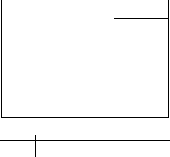
2.Pressing <F2> displays the Main Menu, which looks like this:
PhoenixBIOS Setup Utility
Main Advanced Security Power Boot Exit
Item Specific Help
<Tab>, <Shift-Tab>, or
<Enter> selects field
[16:19:20]
[02/10/2002]
[19077MB]
[Enabled]
[Enabled]
VIA Ezra
933MHz
640KB
228352KB
System Time
System Date:
4Primary Master
4Memory Cache
Quick Boot
Bootl-Time Diagnostic Screen
CPU Type
CPU Speed
System Memory
Extended Memory
F1
ESC
Help
Exit
↑↓
Ö
-/+
Enter
Change Values
Select 4Sub-Menu
F9
F10
Setup Defaults
Save and Exit
Select Item
Select Menu

4-2
The Legend Bar
Use the keys listed in the legend bar on the bottom to make your
selections or exit the current menu. The chart on the following page
describes the legend keys and their alternates:
Key Function
<F1> or <Alt-H> General Help window (See below).
<Esc> Exit this menu.
Ö Arrow keys Select a different menu.
↑ or ↓ arrow keys Move cursor up and down.
<Tab>or<Shift-Tab> Cycle cursor up and down.
<Home> or <End> Move cursor to top or bottom of window.
<PgUp> or <PgDn> Move cursor to next or previous page.
<F5> or <-> Select the Previous Value for the field.
<F6> or <+> or <Space> Select the Next Value for the field.
<F9> Load the Default Configuration values for this menu.
<F10> Save and exit.
<Enter> Execute Command or Select P Submenu.
<Alt-R> Refresh screen.
To select an item, use the arrow keys to move the cursor to the field
you want. Then use the plus-and-minus value keys to select a value for
that field. The Save Values commands in the Exit Menu save the values
currently displayed in all the menus.
To display a sub menu, use the arrow keys to move the cursor to the
sub menu you want. Then press <Enter>. A pointer (4) marks all sub
menus.
4-3
Main Menu Selections
PhoenixBIOS Setup Utility
Main Advanced Security Power Boot Exit
Item Specific Help
<Tab>, <Shift-Tab>, or
<Enter> selects field
Setting System Time & Date
Feature Options Description
System Time HH:MM:SS Set the system time.
The hour setting uses the 24-hour system.
System Date MM/DD/YYYY Set the system date.
Primary Master
Pressing enter Primary Master selection to configure the main IDE HDD,
which fits into the computer’s HDD bay.
HDD Type
This setting has several options for choosing which method setup will
use to detect the hard disk.
Auto (Default setting) – This slows setup to determine the hard disk’s
type and other information. It automatically loads the information into
the BIOS.
[16:19:20]
[02/10/2002]
[19077MB]
[Enabled]
[Enabled]
VIA Ezra
933MHz
640KB
228352KB
System Time
System Date:
4Primary Master
4Memory Cache
Quick Boot
Bootl-Time Diagnostic Screen
CPU Type
CPU Speed
System Memory
Extended Memory
F1
ESC
Help
Exit
↑↓
Ö
-/+
Enter
Change Values
Select
4
Sub-Menu
F9
F10
Setup Defaults
Save and Exit
Select Item
Select Menu
4-4
None – Autotyping is not able to supply the type or no hard disk is
installed.
User – This allows you to fill the hard-disk drive information in the
Cylinders, Heads and Sectors/Track fields. It automatically calculates
“ size” based on this information.
LBA Mode Control – “Enable” is default setting, because most hard
disks capacity is larger than 528MB.
32-Bit I/O – Most new hard disks can support this higher rate. Enables
32-bit communication between CPU and IDE card. Requires PCI or
local bus.
Transfer Mode – Selects the method for transferring the data between
the hard disk and system memory.
Memory Cache
Enabling cache saves time for the CPU by holding data most recently
accessed in regular memory (dynamic RAM or DRAM) in a special
storage area of static RAM (SRAM), which is faster. Before accessing
regular memory, the CPU first accesses the cache. If it does not find the
data it is looking for there, it accesses regular memory. Selecting
Memory Cache" from the Main menu displays a menu like the one
shown here. The actual features displayed depend on your system's
hardware.
Quick Boot
When you enable this selection, the system wills skip some POST
testing, speeding boot time.
Boot-Time Diagnostic Screen
Display diagnostic screen or logo screen during POST. The default
setting is “disabled”.

4-5
System Memory & Extended Memory
System Memory:Display amount of conventional memory detected
during boot up.
Extended Memory:Display the amount of extended memory detected
during boot up.
The Advance Menu
PhoenixBIOS Setup Utility
Main Advanced Security Power Boot Exit
Item Specific Help
Select options for
Advanced Chipset
functions
Legacy USB Support
You can either enable or disable the system’s support for the USB port
in DOS mode. The default setting is enabled.
Large Disk Access Mode
Select DOS if you have DOS. Select other if you have another operating
system such as UNIX. A large disk is one that has more than 1024
cylinders, more than 16 heads, or more than 63 tracks per sector. The
default setting is DOS.
[Enabled]
[DOS]
[Win 95]
[NO]
[Enabled]
[64M]
[32MB]
[4X]
[Both]
Legacy USB Support
Large Disk Access Mode
Installed OS
Reset Configuration Data
PCI Delay Transaction
Aperture Size
Frame Buffer Size
AGP Rate
Display Device Selection
F1
ESC
Help
Exit
↑↓
Ö
-/+
Enter
Change Values
Select
4
Sub-Menu
F9
F10
Setup Defaults
Save and Exit
Select Item
Select Menu
Setup Warning
Setting items on this menu to incorrect
values may cause your system to malfunction.

4-6
Installed OS
Select the operating system you use more often.
Reset Configuration Data
When you select yes the bios will erase all configuration data in a
section of memory for ESCD (Extended System Configuration Data)
which stores the configuration settings for non-PnP plug-in devices.
Select Yes when required to restore the manufacturer's defaults. The
default setting is NO.
The Security menu
PhoenixBIOS Setup Utility
Main Advanced Security Power Boot Exit
Item Specific Help
Supervisor password
controls access to the
Setup utility.
Supervisor Password
The changes you make affect the access to the Setup utility itself, and
also access to your machine as it boots up after you turn it on. These
setting do not affects your machine or network passwords which will be
set in your software OS.
User Password
The user password is under the supervision of the administrator
Clear
Clear
[Enter]
[Enter]
[Disable]
[Normal]
[Disable]
[Disable]
[Disable]
Supervisor Password Is
:
User Password Is:
Set Supervisor Password
Set User Password
Diskette access:
Fixed disk boot sector:
Virus check reminder:
System backup reminder:
Password on boot:
F1
ESC
Help
Exit
↑↓
Ö
-/+
Enter
Change Values
Select 4Sub-Menu
F9
F10
Setup Defaults
Save and Exit
Select Item
Select Menu
4-7
password. You can set the user password to be required for starting up
the system and/or entering SCU when the administrator password has
been set. Beside, the user password only allows you to use some
limited items for setting in the SCU.
Set Supervisor Password
Pressing <Enter> displays the dialog box for entering the Supervisor
password. In related systems, this password gives restricted access to
Setup menus.
Set User Password
Pressing <Enter> displays dialog box for entering the User password.
In related systems, this password gives full access to Setup menus.
Diskette access
You can either enable or disable requires a password to boot from or
access the floppy disk.
Fixed disk boot sector
You can select normal or write option. Write protects the boot sector on
the hard disk for virus protection. Requires a password to format or
Fdisk the hard disk. The default setting is normal
Virus check reminder and System backup reminder
Display a message during boot up asking (Y/N) if you have backed up
the system or scanned it for viruses. Message returns on each boot until
you respond with “Y”.
Daily displays the message on the first boot of the day, Weekly on the
first boot after Sunday, and Monthly on the first boot of the month. The
default setting is disabled.
Password on boot
Set a password for booting the computer. Only users who use correct
password can boot the system. The default setting is disabled.

4-8
The Boot Menu
PhoenixBIOS Setup Utility
Main Advanced Security Power Boot Exit
Item Specific Help
Keys used to view or
configure devices:
<Enter> expands or
collapses devices with a
+ or p <Ctrl+ Enter>
expands all <Shift+1>
enable or disables a
device. <+> and <->
moves the device up or
down. <n> May move
removable device
between the Hard Disk
or Removable Disk <d>
Remove a device that is
not installed
After you turn on your computer, it will attempt to load the operating
system (such as Windows XP) from the device of your choice. If it
cannot find the operating system on that device, it will attempt to load it
from one or more other devices in the order specified in the Boot Menu.
Boot devices (i.e., with access to an operating system) can include:
hard drives, floppy drives, CD ROMs, removable devices (e.g., USB
Floppy Disk), and network cards.
Specifying any device as a boot device on the Boot Menu requires the
availability of an operating system on that device. Most PCs come with
an operating system already installed on hard-drive C:.
Use this menu to arrange to specify the priority of the devices from
which the BIOS will attempt to boot the Operating System. In the
example above, the BIOS will attempt first to boot from the CD-ROM
Removable Devices
CD-ROM Drive
* Hard Drive
F1
ESC
Help
Exit
↑↓
Ö
-/+
Enter
Change Values
Select 4Sub-Menu
F9
F10
Setup Defaults
Save and Exit
Select Item
Select Menu

4-9
drive (the only Removable Device listed). Failing that, it will attempt to
boot from the Primary Master hard disk, and so on down the list.
Removable Devices, Hard Drive, and Network Boot are the generic
types of devices on your system from which you can boot an operating
system. You may have more than one device of each type. If so, the
generic type is marked with a plus or minus sign. Use the <Enter> key
to expand or collapse the devices marked with <+> or <->. Press
<Ctrl+Enter> to expand all such devices.
Note: Floppy drives are not managed on this menu as part of
Removable Devices.
To change a device’s priority on the list, first select it with the
up-or-down arrows, and move it up or down using the <+> and <-> keys.
Pressing <n> moves a device between the Removable Devices and
Hard Drive. Pressing <Shift+1> enables or disables a device.
The Exit Menu
PhoenixBIOS Setup Utility
Main Advanced Security Power Boot Exit
Item Specific Help
Exit System Setup and
save your changes to
CMOS.device that is not
installed
Exit Saving Changes
After making your selections on the Setup menus, always select either
"Saving Values" or "Save Changes." Both procedures store the
selections displayed in the menus in CMOS (short for "battery-backed
Exit Saving Changes
Exit Discarding Changes
Load Setup Defaults
Discard Changes
Save Changes
F1
ESC
Help
Exit
↑↓
Ö
-/+
Enter
Change Values
Select
4
Sub-Menu
F9
F10
Setup Defaults
Save and Exit
Select Item
Select Menu
4-10
CMOS RAM") a special section of memory that stays on after you turn
your system off. The next time you boot your computer, the BIOS
configures your system according to the Setup selections stored in
CMOS.
During boot up, PhoenixBIOS attempts to load the values saved in
CMOS. If those values cause the system boot to fail, reboot and press
<F2> to enter Setup. In Setup, you can get the Default Values (as
described below) or try to change the selections that caused the boot to
fail.
Exit Discarding Changes
Use this option to exit Setup without storing in CMOS any new
selections you may have made. The selections previously in effect
remain in effect.
Load Setup Defaults
To display the default values for all the Setup menus, select "Load
Setup Defaults" from the Main Menu.
If, during boot up, the BIOS program detects a problem in the integrity of
values stored in CMOS. The CMOS values have been corrupted or
modified incorrectly, perhaps by an application program that changes
data stored in CMOS.
Press <F1> to resume the boot or <F2> to run Setup with the ROM
default values already loaded into the menus. You can make other
changes before saving the values to CMOS.
Discard Changes
If, during a Setup Session, you change your mind about changes you
have made and have not yet saved the values to CMOS, you can
restore the values you previously saved to CMOS.
4-11
Save Changes
Selecting “Save Changes” saves all the selections without exiting Setup.
You can return to the other menus if you want to review and change
your selections.

5-1
Chapter 5: Expanding The Notebook
This chapter delivers the information about expanding your notebook
computer by connecting other peripheral devices.
Using PC Cards
This computer is installed with one PC card slot on the left side of the
notebook. PC Cards are credit card-sized peripheral products based on
the standards developed by PCMCIA (Personal Computer Memory
Card International Association) such as a Wireless LAN card, a flash
memory card, SCSI card and so on.
PC Card Type
This computer’s PC Card slot allows uses a type II card.
Card Bus Support
This computer’s PC Card slot supports CardBus specification. CardBus
is the 32-bit extension of the original 16-bit PC Card specification.
CardBus cards provide higher performance.
Inserting and Removing a PC Card
You can install or change PC cards while your notebook is turned on.
Note
:
Some PC Cards require additional system resources. Before
using this PC Card, you must to free other system resource for the PC
Card.
PC Card Slot Eject Button
5-2
1. Orient the card correctly. The label side of the card faces up. One of
the narrow edges has a row of pinholes. This edge inserts into the
slot.
2. Insert the card into the slot. The slot had protected by cover. The
covers will fold out of the way when you insert the card. When the
card is nearly all the way inserted, press quite firmly to ensure that
the card mates properly with the connector inside the slot.
3. Your notebook will emit two beeps (in rising tones) to let you know
that the card has been recognized by the system. If Windows has
the appropriate drivers to use the card, they will be loaded
automatically. For some cards, you may have to install drivers or
software, supplied by the card manufacturer.
4. Before ejecting a CardBus card, it is important that you tell
Windows to stop using the card. Click on the card icon on the right
side of the Windows task bar. When the stop button appears, click
on it. Windows will display a message that the card can now be
safely removed.
5. When you insert a card, the card eject button will be forced outward
from the edge of the case. To eject a card from the slot, press the
eject button back into the notebook. The card will disconnect from
the internal connector and you can remove it from the slot. The
notebook will emit two beeps (in falling tones) to let you know that
the card has ejected.
5-3
Connecting a USB 2.0 Device
The USB 2.0 is the new generation interface, which supports 480Mbps
(max) data transfer rate.
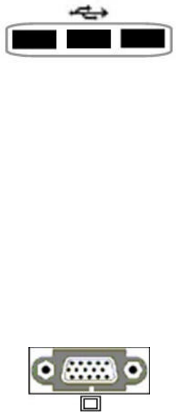
This computer has three USB 2.0 (Universal Serial Bus) ports on the
left side of the computer for connecting USB devices such as mouse,
external USB floppy disk drive, external USB optical drive, camera and
so on. It supports “Plug and Play” technology so you can install and
remove USB devices without turning off the computer.
NOTE: Please download the newest USB 2.0 drive from the Internet
Connecting an External Monitor
This computer supports one 15-pin external monitor port on the left of
the computer for external display device.
IF you want to use a larger screen display screen with higher resolution,
you can attach a video cable into this port to connect your notebook to
the external CRT monitor or LCD monitor.
5-4
Internal Components Upgrade
Here is a list of upgrading options that are not user-serviceable:
1. DDR Memory
2. Internal hard disk
Warring
:
We recommend that you contact your dealer and ask
them to install any additional components. Installing these
components by yourself may cause damage to your system.