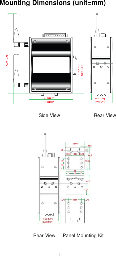
Moxa AWK-3121 Industrial IEEE 802.11a/b/g wireless Access Point/Bridge/Client User Manual AWK 3121 QIG 1e
Moxa Inc. Industrial IEEE 802.11a/b/g wireless Access Point/Bridge/Client AWK 3121 QIG 1e
Moxa >
Contents
- 1. Revised Manual
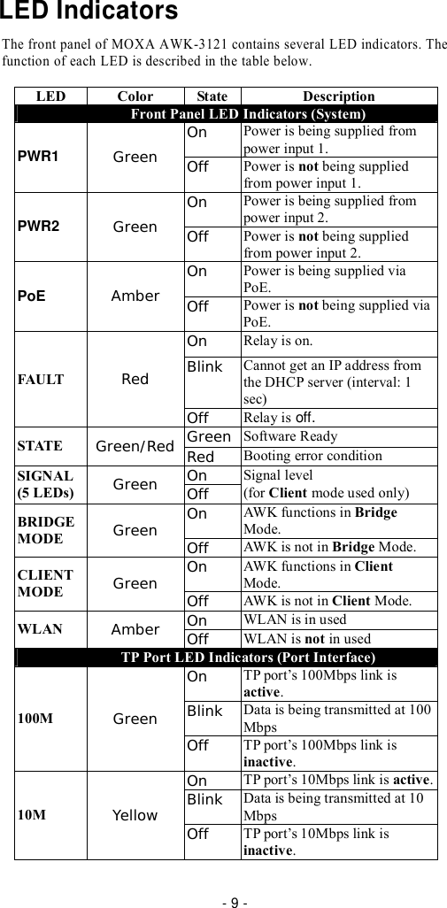
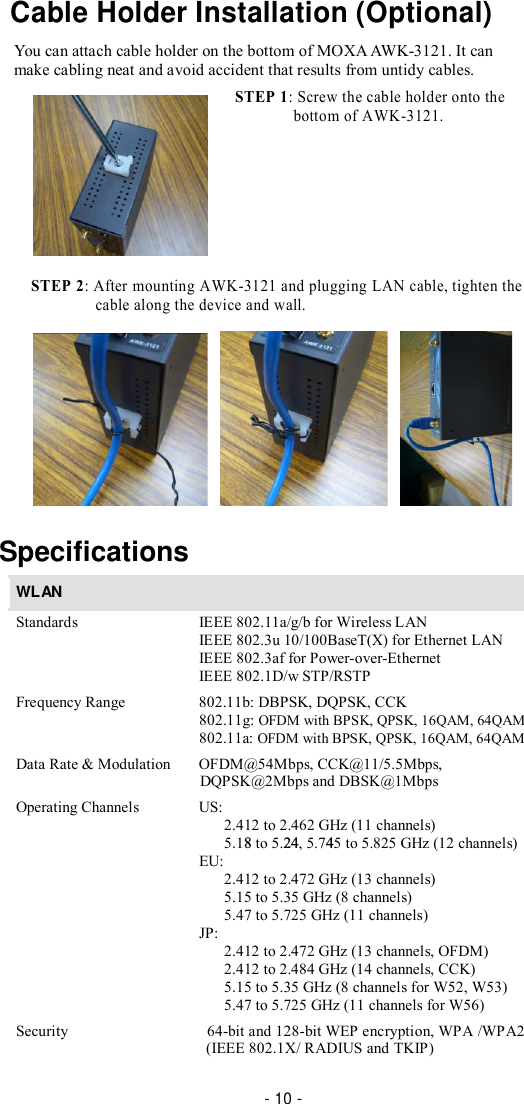
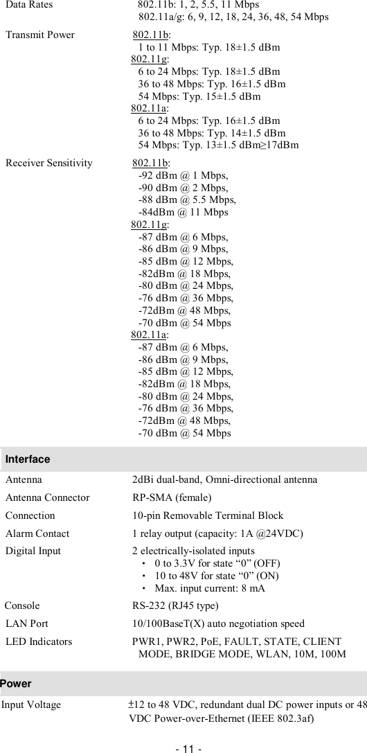
- 2. User Manual
Revised Manual