Moxa AWK-5222 Industrial IEEE 802.11a/b/g Dual-RF AP/Bridge/Client User Manual AirWorks AWK 5222 User s Manual v1
Moxa Inc. Industrial IEEE 802.11a/b/g Dual-RF AP/Bridge/Client AirWorks AWK 5222 User s Manual v1
UserManual.wiki
>
Moxa
>
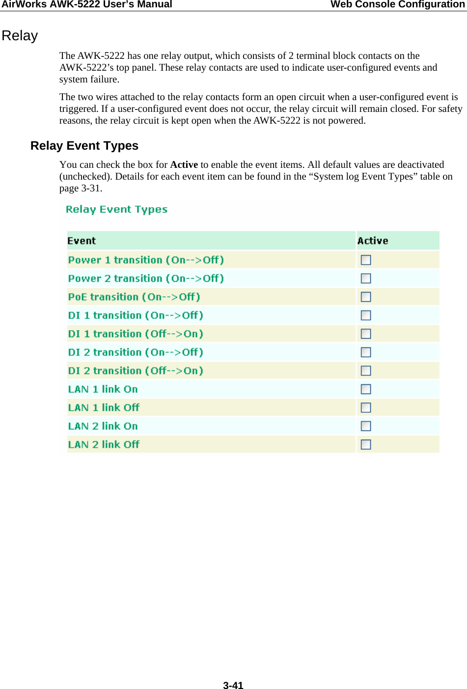
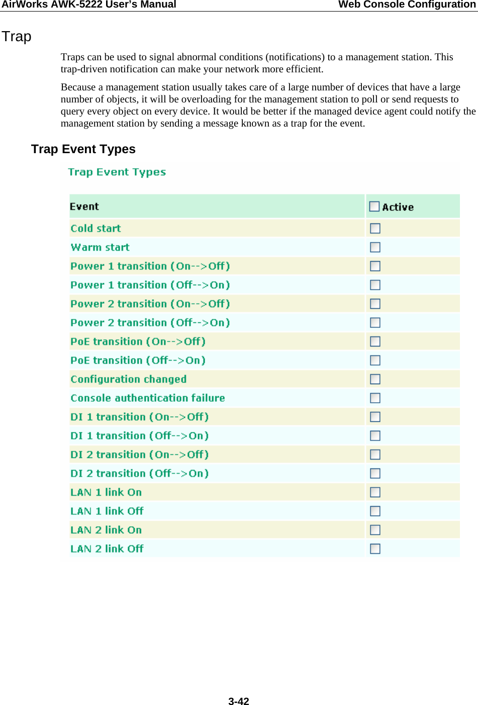
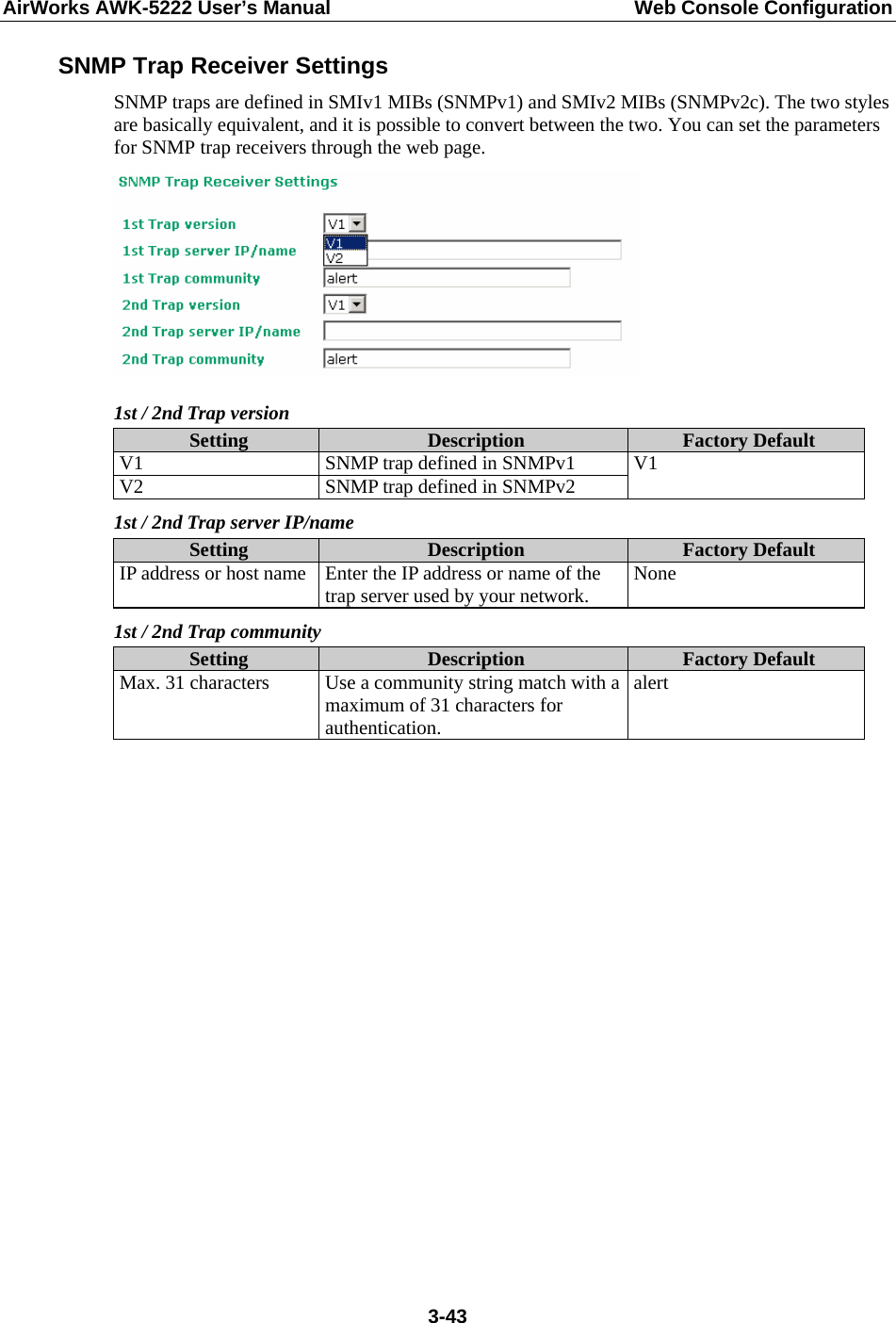
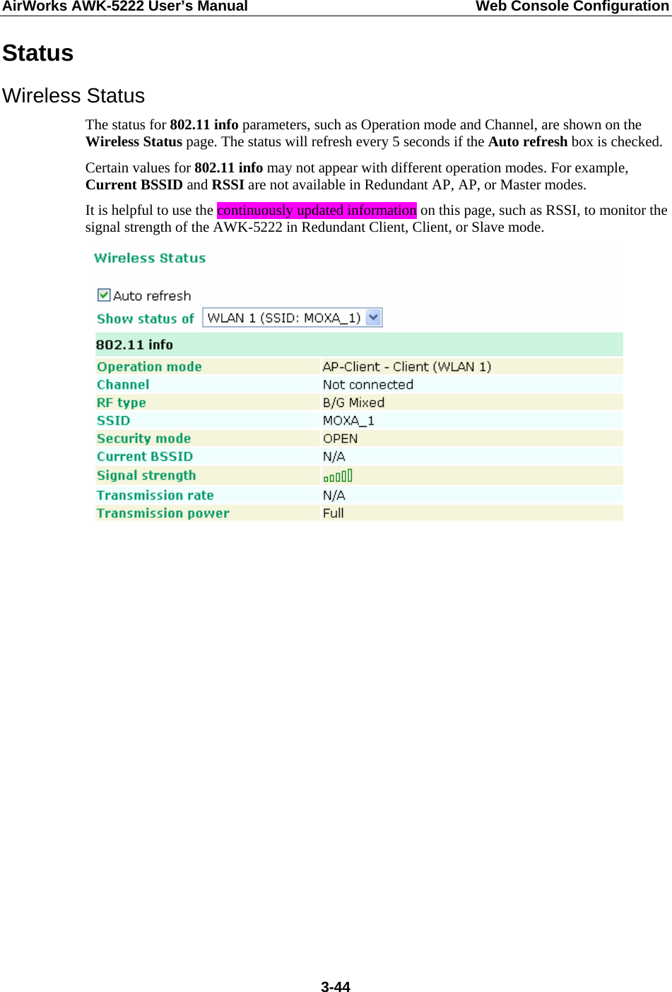
AWK 5222 User Manual
User Manual
Navigation menu
Upload a User Manual
Namespaces
Wiki Guide
HTML
PDF
Info
Views
User Manual
Discussion / Help
Navigation