Moxa AWK-3121 Industrial IEEE 802.11a/b/g wireless Access Point/Bridge/Client User Manual AWK 3121 QIG 1e
Moxa Inc. Industrial IEEE 802.11a/b/g wireless Access Point/Bridge/Client AWK 3121 QIG 1e
Moxa >
Contents
- 1. Revised Manual
- 2. User Manual
Revised Manual


Overview
Are your applications hard to wire, or are your wiring costs out of control? Are
you already using mobile equipment that connects over a TCP/IP network? If
so, then what you need is the AWK-3121Access Point/Bridge/AP Client. The
AWK-3121 is rated to operate at temperatures ranging from 0 to 60°C for
standard models and -40 to 75°C for extended temperature models, and is
rugged enough for any harsh industrial environment. Installation is easy, with
either DIN-Rail mounting or distribution boxes. The DIN-rail mounting ability,
wide operating temperature range, and IP30 housing with LED indicators make
the AWK-3121 a convenient yet reliable solution for any industrial wireless
application.
Package
Checklist
MOXA AWK-3121 is shipped with the following items. If any of these items is
missing or damaged, please contact your customer service representative for
assistance.
l 1 Í AWK-3121
l 2 Í Swivel-type antenna (2dBi, RP-SMA, 2.4&5GHz)
l 1 Í Quick installation guide
l 1 Í Software CD
l 1 Í MOXA product warranty booklet
l 1 Í Cable holder with a screw
l 2 Í Protective cap
Installation
and Configuration
Before installing AWK-3121, check to make sure that all items in the Package
Checklist are in the box. In addition, you will need access to a notebook
computer or PC equipped with an Ethernet port. AWK-3121 has a default IP
address that you must use when connecting to AWK-3121 for the first time.
Step
1:
Select
the
Power
Source
AWK-3121 can be powered by a DC power input or PoE (Power over
Ethernet). AWK-3121 will use the power source that you choose.
Step
2:
Connect
AWK-3121
to
a
notebook
or
PC
Since AWK-3121 supports MDI/MDI-X auto-sensing, you can use either a
straight-through cable or cross-over cable to connect AWK-3121 to the
notebook, if the LED on AWK-3121’s LAN port lights up, it means the
connection is established.
Step
3:
Set
up
the
computer’s
IP
address
Set an IP address on the same subnet as the AWK-3121. Since AWK-3121’s
default IP address is 192.168.127.253, and the subnet mask is 255.255.255.0,
you should set the IP address of the computer to 192.168.127.xxx.
Step
4:
Use
the
web-based
manager
to
configure
AWK-3121
Open your computer’s web browser and then type http://192.168.127.253 in
the address box to access the homepage of the web-based Network Manager.
Before the homepage opens, you will need to enter the user name and
password as shown in the following figure. For first-time configuration, enter
the default user name and password and then click on OK:
User
name:
admin
Password:
root
-
1
-

NOTE
For
security
reasons,
we
strongly
recommend
changing
the
password.
To
do
so,
open
the
Network
Manager
homepage,
click
on
Maintenance
>
Password
,
and
then
follow
the
onscreen instructions.
Step
5:
Select
the
operation
mode
for
AWK-3121
By default, AWK-3121’s operation mode is set to AP. You can change the
setting if you would like a Client mode or other operation mode.
NOTE
To make the change effect, you must click
Activate
button
after you change the settings.
Step
6:
Test
communications
We describe two test methods. Use the first method if you are using only one
AWK-3121, and use the second method if you are using two or more
AWK-3121s
Testing Method for one AWK-3121
If you are only using one AWK-3121, you will need a second notebook
computer equipped with a WLAN card. Configure the WLAN card for
connecting to AWK-3121 (the default SSID is MOXA), and change the IP
address of notebook B so that it is on the same subnet as notebook A.
After connecting the WLAN card, connect to AWK-3121 and open a DOS
window on notebook B. At the prompt, type
ping
IP
address
of
notebook
A
and then press Enter key. A “Reply from IP address …” response means the
communication was successful. A “Request timed out.” response means the
communication failed. In this case, recheck the configuration to make sure
the connections are correct.
Testing Method for two or more AWK-3121s
If you have two or more AWK-3121s, you will need a second notebook
computer equipped with an Ethernet port. Use the default settings for the
first AWK-3121, and change the second or third AWK-3121 to AP Client
mode and then configure the notebook and AWK-3121s properly.
After setting up the testing environment, open a DOS window on notebook
B. At the prompt, type
ping
IP
address
of
notebook
A
and then press Enter key. A “Reply from IP address …” response means the
communication was successful. A “Request timed out.” response means the
communications failed. In this case, recheck the configuration to make sure
the connections are correct.
-
2
-
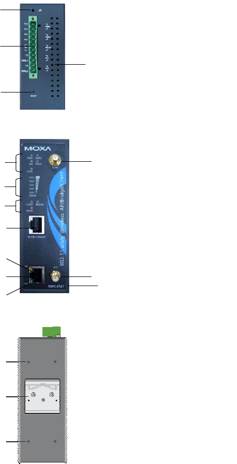
Panel
Layout
of
AWK-3121
Top Panel View
Front Panel View
Rear Panel View
-
3
-
5
6
7
8
9
1
2
3
4
12
13
10
11 14
15
16
15
1. Grounding
screw
2. Terminal
block
for PWR1
,
PWR2, Relay, DI1 and
DI2
3. Reset button
4.
Heat
dissipation
orifices
5. System LEDs: PWR1,
PWR2, PoE, FAULT
and STATE LEDs
6.
LEDs for signal strength
7. WLAND LEDs: CLIENT
BRIDGE and WLAN
LEDs
8.
RS-232 console port
9.
10/100BaseT(X)
RJ45
Port
10. 10M LED
11. 100M LED
12.
MAIN
antenna
port
13.
A
UX
antenna
port
14.
Model name
15.
Screw
hole
for
wall
mounting
kit
16.
DIN-Rail
mounting
kit
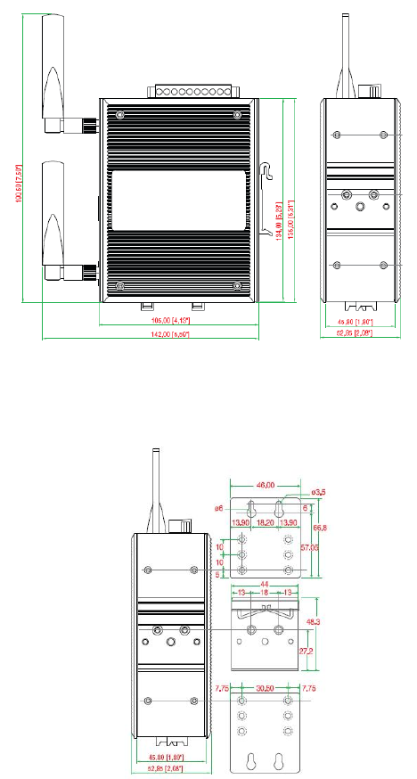
Mounting
Dimensions
(unit=mm)
Side
View
Rear
View
Rear
View
Panel
Mounting
Kit
-
4
-
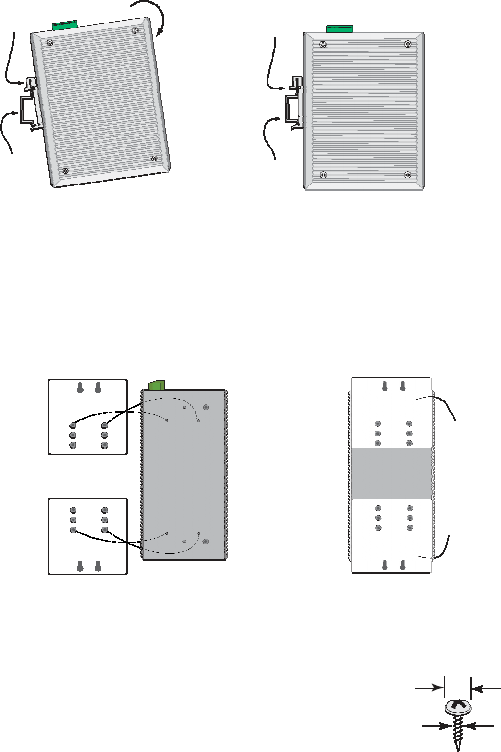
DIN-Rail Mounting
The
aluminum
DIN-Rail
attachment
plate
should
be
fixed
to
the
back
panel
of
AWK-3121
when
you
take
it
out
of
the
box.
If
you
need
to
reattach
the
DIN-Rail
attachment
plate
to
AWK-3121,
make
sure
the
stiff
metal
spring
is
situated
towards
the
top,
as
shown
in
the
figures
below
.
STEP
1
:
Insert
the
top
of
the
DIN-Rail
into
the
slot
just
below
the
stiff
metal
spring.
metal
spring
STEP
2
:
The
DIN-Rail
attachment
unit
will
snap
into
place
as
shown
below.
metal
spring
DIN-Rail
DIN-Rail
To
remove
AWK-3121
from
the
DIN-Rail,
simply
reverse
Steps
1
and
2
above.
Wall Mounting (Optional)
For
some
applications,
you
will
find
it
convenient
to
mount
AWK-3121
on
the
wall,
as
illustrated
below.
STEP
1
:
Remove
the
aluminum
DIN-Rail
attachment
plate
from
AWK-3121,
and
then
attach
the
wall
mount
plates,
as
shown
in
the
diagrams
below.
Top
plate
⇒
Bottom
plate
STEP
2
:
Mounting
AWK-3121
on
the
wall
requires
4
screws.
Use
the
AWK-3121,
with
wall
mount
plates
attached,
as
a
guide
to
mark
the
correct
locations
of
the
4
screws.
The
heads
of
the
screws
should
be
less
than
6.0
mm
in
diameter,
and
the
shafts
should
be
less
than
3.5
mm
in
diameter,
as
shown
in
the
figure
at
the
right.
Do
not
screw
the
screws
in
all
the
way—leave
a
space
of
about
2
mm
to
allow
room
for
sliding
the
wall
mount
panel
between
the
wall
and
the
screws.
6.0
mm
3.5
mm
-
5
-
NOTE
Test
the
screw
head
and
shank
size
by
inserting
the
screw
into
one
of
the
keyhole
shaped
apertures
of
the
Wall
Mounting
Plates,
before
it
is
screwed
into
the
wall.
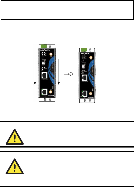
STEP
3
:
Once
the
screws
are
fixed
in
the
wall,
insert
the
four
screw
heads
through
the
large
parts
of
the
keyhole-shaped
apertures,
and
then
slide
AWK-3121
downwards,
as
indicated
below.
Tighten
the
four
screws
for
added
stability.
Wiring
Requirements
ATTENTION
Safety
First!
Be
sure
to
disconnect
the
power
cord
before
installing
and/or
wiring
your
MOXA
AWK-3121.
ATTENTION
Safety
First!
Calculate
the
maximum
possible
current
in
each
power
wire
and
common
wire.
Observe
all
electrical
codes
dictating
the
maximum
current
allowable
for
each
wire
size.
If
the
current
goes
above
the
maximum
ratings,
the
wiring
could
overheat,
causing
serious
damage
to
your
equipment.
You should also pay attention to the following points:
§ Use separate paths to route wiring for power and devices. If power wiring and
device wiring paths must cross, make sure the wires are perpendicular at the
intersection point.
NOTE: Do not run signal or communications wiring and power wiring in the
same wire conduit. To avoid interference, wires with different signal
characteristics should be routed separately.
§ You can use the type of signal transmitted through a wire to determine which
wires should be kept separate. The rule of thumb is that wiring that shares
similar electrical characteristics can be bundled together.
§ Keep input wiring and output wiring separated.
§ It is strongly advised that you label wiring to all devices in the system when
necessary.
-
6
-
Grounding
MOXA
AWK-3121
Grounding
and
wire
routing
help
limit
the
effects
of
noise
due
to
electromagnetic
interference
(EMI).
Run
the
ground
connection
from
the
ground
screw
to
the
grounding
surface
prior
to
connecting
devices.
ATTENTION
This
product
is
intended
to
be
mounted
to
a
well-grounded
mounting
surface
such
as
a
metal
panel.
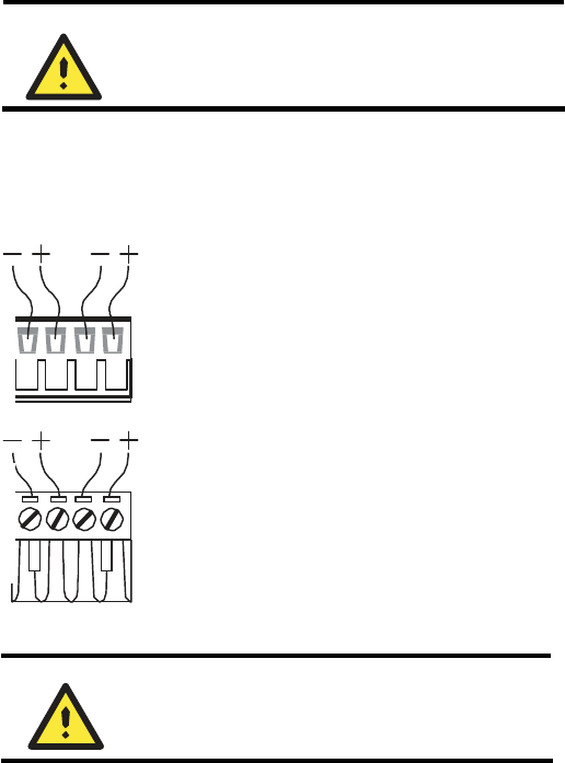
Wiring
the
Redundant
Power
Inputs
The
top
two pairs of
contacts
of
the
10
-contact
terminal block
connector
on
AWK-3121’s
top
panel
are
used
for
AWK-3121’s
two
DC inputs.
Top
and
front
views
of
one
of
the
terminal
block
connectors
are
shown here.
STEP
1
:
Insert
the
negative/positive
DC
wires
into
the
V-/V+
terminals.
STEP
2
:
To
keep
the
DC
wires
from
pulling
loose,
use
a
small
flat-blade
screwdriver
to
tighten
the
wire-clamp
screws
on
the
front
of
the
terminal
block
connector.
Top
View
STEP
3
:
Insert
the
plastic
terminal
block
connector
prongs
into
the
terminal
block
receptor,
which
is
located
on
AWK-3121’s
top
panel.
Front
View
ATTENTION
Before
connecting
AWK-3121
to
the DC power
inputs,
make
sure the
DC
power
source
voltage
is
stable.
Wiring
the
Relay
Contact
AWK-3121 has one relay output, which consists of the two contacts of the
terminal block on AWK-3121’s top panel. Refer to the previous section for
detailed instructions on how to connect the wires to the terminal block
connector, and how to attach the terminal block connector to the terminal
block receptor. This relay contacts are used to detect user-configured events.
The two wires attached to the Fault contacts form an open circuit when a
user-configured event is triggered. If a user-configured event does not
occur, the Fault circuit will be closed.
-
7
-
10-Pin
Description
8-Pin
1
------
2
DSR
1
3
------
2
4
GND
3
5
TxD
4
6
RxD
5
7
GND
6
8
------
7
9
DTR
8
10
------
Wiring
the
Digital
Inputs
AWK-3121 has two sets of digital input—DI1 and DI2. Each DI comprises
two contacts of the 10-pin terminal block connector on AWK-3121's top
panel. You can refer to the section Wiring the Redundant Power Inputs for
detailed instructions on how to connect the wires to the terminal block
connector, and how to attach the terminal block connector to the terminal
block receptor.
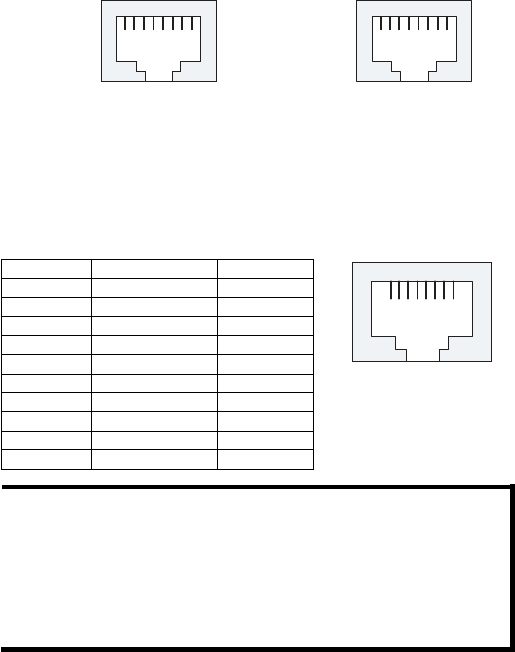
Communication
Connections
10/100BaseT(X) Ethernet Port Connection
The
10/100BaseT(X)
ports
located
on
AWK-3121’s
front
panel
are
used
to
connect
to
Ethernet-enabled
devices.
Below
we
show
pinouts
for
both
MDI
(NIC-type)
ports
and
MDI-X
(HUB/Switch-type)
ports.
RJ45
(8-pin,
MDI)
Port
Pinouts
RJ45
(8-pin,
MDI-X)
Port
Pinouts
Pin Signal
Pin Signal
1 Tx+ 1 8
2 Tx-
3 Rx+
6 Rx-
1 Rx+ 1 8
2 Rx-
3 Tx+
6 Tx-
RS-232 Connection
AWK-3121
has
one
RS-232
(8-pin
RJ45)
console
port,
located
on
the
side
panel. Use
either
an
RJ45-to-DB9
or
RJ45-to-DB25
cable
to
connect
MOXA
AWK-3121’s
console
port
to
your
PC’s
COM
port.
You
may
then
use
a
console terminal
program
to
access
AWK-3121
for
console
c
onfiguration.
Console
Pinouts for 10-pin or 8-pin
RJ45
1
8
NOTE
1.
The
pin
numbers
for
male
DB9
and
DB25
connectors,
and
hole
numbers
for
female
DB9
and
DB25
connectors
are
labeled
on
the
connector.
However,
the
numbers
are
typically
quite
small,
so
you
may
need
to
use
a
magnifying
glass
to
see
the
numbers
clearly.
2.
The
pin
numbers
for
both
8-pin
and
10-pin
RJ45
connectors
(and ports)
are
typically
not
labeled
on
the
connector
(or
port).
Refer
to the
Pinout
diagram
below
to
see
how
RJ45
pins
are
numbered.
-
8
-

LED
Indicators
The
front
panel
of
MOXA
AWK-3121
contains
several
LED
indicators.
The
function
of
each
LED
is
described
in
the
table
below.
LED Color State
Description
Front Panel LED Indicators (System)
On Power is being supplied from
power input 1.
PWR1 Green Off Power is not being supplied
from power input 1.
On Power is being supplied from
power input 2.
PWR2 Green Off Power is not being supplied
from power input 2.
On Power is being supplied via
PoE.
PoE Amber Off Power is not being supplied via
PoE.
On Relay is on.
Blink Cannot get an IP address from
the DHCP server (interval: 1
sec)
FAULT Red
Off Relay is off.
Green
Software Ready
STATE Green/Red
Red Booting error condition
On SIGNAL
(5 LEDs)
Green Off Signal level
(for Client mode used only)
On AWK functions in Bridge
Mode.
BRIDGE
MODE Green Off AWK is not in Bridge Mode.
On AWK functions in Client
Mode.
CLIENT
MODE Green Off AWK is not in Client Mode.
On WLAN is in used
WLAN Amber Off WLAN is not in used
TP Port LED Indicators (Port Interface)
On TP port’s 100Mbps link is
active.
Blink Data is being transmitted at 100
Mbps
100M Green
Off TP port’s 100Mbps link is
inactive.
On TP port’s 10Mbps link is active.
Blink Data is being transmitted at 10
Mbps
10M Yellow Off TP port’s 10Mbps link is
inactive.
-
9
-
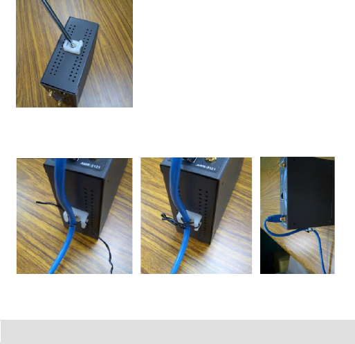
Cable Holder Installation (Optional)
You can attach cable holder on the bottom of MOXA AWK-3121. It can
make cabling neat and avoid accident that results from untidy cables.
STEP
1
:
Screw the cable holder onto
the
bottom of AWK-3121.
STEP
2
:
After mounting AWK-3121 and plugging LAN cable, tighten the
cable along the device and wall.
Specifications
WLAN
Standards IEEE 802.11a/g/b for Wireless LAN
IEEE 802.3u 10/100BaseT(X) for Ethernet LAN
IEEE 802.3af for Power-over-Ethernet
IEEE 802.1D/w STP/RSTP
Frequency Range 802.11b: DBPSK, DQPSK, CCK
802.11g: OFDM with BPSK, QPSK, 16QAM, 64QAM
802.11a: OFDM with BPSK, QPSK, 16QAM, 64QAM
Data Rate & Modulation OFDM@54Mbps, CCK@11/5.5Mbps,
DQPSK@2Mbps and DBSK@1Mbps
Operating Channels US:
2.412 to 2.462 GHz (11 channels)
5.18 to 5.24, 5.745 to 5.825 GHz (12 channels)
EU:
2.412 to 2.472 GHz (13 channels)
5.15 to 5.35 GHz (8 channels)
5.47 to 5.725 GHz (11 channels)
JP:
2.412 to 2.472 GHz (13 channels, OFDM)
2.412 to 2.484 GHz (14 channels, CCK)
5.15 to 5.35 GHz (8 channels for W52, W53)
5.47 to 5.725 GHz (11 channels for W56)
Security 64-bit and 128-bit WEP encryption, WPA /WPA2
(IEEE 802.1X/ RADIUS and TKIP)
-
10
-
Data Rates 802.11b: 1, 2, 5.5, 11 Mbps
802.11a/g: 6, 9, 12, 18, 24, 36, 48, 54 Mbps
Transmit Power 802.11b:
1 to 11 Mbps: Typ. 18±1.5 dBm
802.11g:
6 to 24 Mbps: Typ. 18±1.5 dBm
36 to 48 Mbps: Typ. 16±1.5 dBm
54 Mbps: Typ. 15±1.5 dBm
802.11a:
6 to 24 Mbps: Typ. 16±1.5 dBm
36 to 48 Mbps: Typ. 14±1.5 dBm
54 Mbps: Typ. 13±1.5 dBm≥17dBm
Receiver Sensitivity 802.11b:
-92 dBm @ 1 Mbps,
-90 dBm @ 2 Mbps,
-88 dBm @ 5.5 Mbps,
-84dBm @ 11 Mbps
802.11g:
-87 dBm @ 6 Mbps,
-86 dBm @ 9 Mbps,
-85 dBm @ 12 Mbps,
-82dBm @ 18 Mbps,
-80 dBm @ 24 Mbps,
-76 dBm @ 36 Mbps,
-72dBm @ 48 Mbps,
-70 dBm @ 54 Mbps
802.11a:
-87 dBm @ 6 Mbps,
-86 dBm @ 9 Mbps,
-85 dBm @ 12 Mbps,
-82dBm @ 18 Mbps,
-80 dBm @ 24 Mbps,
-76 dBm @ 36 Mbps,
-72dBm @ 48 Mbps,
-70 dBm @ 54 Mbps
Interface
Antenna 2dBi dual-band, Omni-directional antenna
Antenna Connector RP-SMA (female)
Connection 10-pin Removable Terminal Block
Alarm Contact 1 relay output (capacity: 1A @24VDC)
Digital Input 2 electrically-isolated inputs
• 0 to 3.3V for state “0” (OFF)
• 10 to 48V for state “0” (ON)
• Max. input current: 8 mA
Console RS-232 (RJ45 type)
LAN Port 10/100BaseT(X) auto negotiation speed
LED Indicators PWR1, PWR2, PoE, FAULT, STATE, CLIENT
MODE, BRIDGE MODE, WLAN, 10M, 100M
Power
Input Voltage ±12 to 48 VDC, redundant dual DC power inputs or 48
VDC Power-over-Ethernet (IEEE 802.3af)
-
11
-

Input Current (@24V) 0.3A
Overload Current Protection 1.6A
Reverse Polarity Protection Present
Mechanical
Casing IP30 protection, aluminum case
Installation DIN-Rail or wall mounting
Dimensions 53.6 x 135 x 105 mm (2.11 x 5.31 x 4.13 in)
Weight 850 g
Environmental
Operating Temperature Standard models: 0 to 60°C (32 to 140°F)
Wide Temp. Models: -40 to 75°C (-40 to 167°F)
Storage Temperature -40 to 85°C (-40 to 185°F)
Ambient Relative Humidity 5 to 95% (non-condensing)
Regulatory Approvals
Radio EN300 328
EMC EN301 489-1/-17
EMI FCC Part 15
WARRANTY 5 years
MOXA
Internet
Services
Customer satisfaction is our number one concern, and to ensure that
customers receive the full benefit of our products, Moxa Internet Services has
been set up to provide technical support, driver updates, product information,
and user’s manual updates.
The following services are provided:
E-mail for technical support: support@moxa.com
World Wide Web site for product information: http://www.moxa.com
-
12
-
FEDERAL COMMUNICATIONS COMMISSION INTERFERENCE STATEMENT
This equipment has been tested and found to comply with the limits for a Class B digital
device, pursuant to Part 15 of the FCC Rules. These limits are designed to provide
reasonable protection against harmful interference in a residential installation. This
equipment generates, uses and can radiate radio frequency energy and, if not installed
and used in accordance with the instructions, may cause harmful interference to radio
communications. However, there is no guarantee that interference will not occur in a
particular installation. If this equipment does cause harmful interference to radio or
television reception, which can be determined by turning the equipment off and on, the
user is encouraged to try to correct the interference by one or more of the following
measures:
– Reorient or relocate the receiving antenna.
– Increase the separation between the equipment and receiver.
– Connect the equipment into an outlet on a circuit different from that to which the
receiver is connected.
– Consult the dealer or an experienced radio/TV technician for help.
CAUTION:
Any changes or modifications not expressly approved by the party responsible for
compliance could void the user's authority to operate the equipment.
This device complies with Part 15 of the FCC Rules. Operation is subject to the following
two conditions:
(1) This device may not cause harmful interference and
(2) This device must accept any interference received, including interference that may
cause undesired operation.
FCC RF Radiation Exposure Statement
This equipment must be installed and operated in accordance with provided instructions
and the antenna(s) used for this transmitter must be installed to provide a separation
distance of at least 20 cm from all persons and must not be co-located or operating in
conjunction with any other antenna or transmitter. End-users and installers must be
provide with antenna installation instructions and transmitter operating conditions for
satisfying RF exposure compliance.
Outdoor operations in the 5.15-5.25GHz band is prohibited.