Moxa W1 MiiNePort W1 series Embedded Serial Device Server User Manual
Moxa Inc. MiiNePort W1 series Embedded Serial Device Server
Moxa >
user manual

MiiNePort W1 Series User’s Manual
First Edition, March 2012
www.moxa.com/product
© 2012 Moxa Inc. All rights reserved.

MiiNePort W1 Series User’s Manual
The software described in this manual is furnished under a license agreement and may be used only in accordance with
the terms of that agreement.
Copyright Notice
© 2012 Moxa Inc. All rights reserved.
Trademarks
The MOXA logo is a registered trademark of Moxa Inc.
All other trademarks or registered marks in this manual belong to their respective manufacturers.
Disclaimer
Information in this document is subject to change without notice and does not represent a commitment on the part of
Moxa.
Moxa provides this document as is, without warranty of any kind, either expressed or implied, including, but not limited
to, its particular purpose. Moxa reserves the right to make improvements and/or changes to this manual, or to the
products and/or the programs described in this manual, at any time.
Information provided in this manual is intended to be accurate and reliable. However, Moxa assumes no responsibility for
its use, or for any infringements on the rights of third parties that may result from its use.
This product might include unintentional technical or typographical errors. Changes are periodically made to the
information herein to correct such errors, and these changes are incorporated into new editions of the publication.
Technical Support Contact Information
www.moxa.com/support
Moxa
Americas
Toll
-free: 1-888-669-2872
Tel:
+1-714-528-6777
Fax:
+1-714-528-6778
Moxa China (Shanghai office)
Toll
-free: 800-820-5036
Tel:
+86-21-5258-9955
Fax:
+86-21-5258-5505
Moxa Europe
Tel:
+49-89-3 70 03 99-0
Fax:
+49-89-3 70 03 99-99
Moxa As
ia-Pacific
Tel:
+886-2-8919-1230
Fax:
+886-2-8919-1231
Table of Contents
1. Introduction ...................................................................................................................................... 1-1
Overview ........................................................................................................................................... 1-2
Product Features ................................................................................................................................ 1-2
Product Specifications ......................................................................................................................... 1-2
2. Chapter Title ..................................................................................................................................... 2-1
Dimensions ........................................................................................................................................ 2-2
MiiNePort W1 Pin Assignments ............................................................................................................. 2-3
Wiring Requirements ........................................................................................................................... 2-4
Black Diagram .................................................................................................................................... 2-4
Hardware Installation .......................................................................................................................... 2-5
Software Installation ........................................................................................................................... 2-5
3. Compliance Notice ............................................................................................................................. 3-1
Federal Communications Commission Statement .................................................................................... 3-2
Labeling Requirements ........................................................................................................................ 3-2
End Product Labeling ........................................................................................................................... 3-2
Information for OEM and Integrators ..................................................................................................... 3-3
Antenna List ....................................................................................................................................... 3-3

1
1. Introduction
The MiiNePort W1 series provides serial to 802.11 b/g embedded wireless solution with compact size, and ultra
low power consumption features. Numerous operation modes are designed to fulfill the requirements of
embedded module application. Complete driver support reduces software redesign effort and accelerate time
to market.
The following topics are covered in this chapter:
Overview
Product Features
Product Specifications

MiiNePort W1 Series Introduction
21-
Overview
The MiiNePort W1 series is a very compact module that installs in a serial device to connect it to a wireless LAN.
With such a small size, around half the size of a credit card., it can be installed into almost any kind of serial
device. The MiiNePort W1 series also comes with a built-in TCP/IP stack for fast integration with your serial
devices. This means that your engineers can spend less time with the TCP/IP and wireless details, and more
time on developing major features, shortening your product’s time to market. The reliable TCP/IP
communication firmware can be configured easily using a Windows utility, a web browser, or Telnet console.
An integration kit and a complete development kit are both available for evaluation and development use. The
development kit contains a development board, documents, sample code, cables, and accessories.
Product Features
The MiiNePort W1 series has the following features:
• 802.11 b/g compatible
• AES, WEP 64/128-bit, WPA, WPA2, PSK, 802.11i security support
• 1 Serial port, up to 921.6k bps
• 1 Ethernet port, 10/100Mbps
• SSL/SSH support for configuration
• Fast roaming to enhance connection reliability
Product Specifications
Form Factor
Type:
Drop-in module
Dimensions:
44.4 x 44.4 mm (1.75 x 1.75 in)
System
Information
Ethernet Interface
Number of Ports:
1
Speed:
10/100 Mbps, auto MDI/MDIX
WLAN Interface
Standard Compliance:
IEEE 802.11b/g
Network Modes:
Infrastructure mode (b/g), Ad-Hoc mode (b/g)
Spread Spectrum Technology:
DSSS, CCK, OFDM
Transmit Power:
IEEE 802.11b: 16 dBm (typical)
IEEE 802.11g: 14 dBm (typical)
Receive Sensitivity:
-71 dBm (Min)
Transmission Rate:
IEEE 802.11b: 11 Mbps
IEEE 802.11g: 54 Mbps
Transmission Distance:
Up to 100 meters (in open areas)
Wireless
Security:
AES, WEP 64/128
-bit, WPA, WPA2, PSK, 802.11i
Serial Interface
Number of Ports:
1
Serial Standards:
TTL
Serial Communication Parameters
Data Bits:
7, 8

MiiNePort W1 Series Introduction
31-
Stop Bits:
1, 2
Parity:
None, Even, Odd
Flow Control:
RTS/CTS, XON/XOFF
Baudrate:
50 bps to 921.6 Kbps
Serial Signals
TTL:
TxD, RxD, RTS, CTS, DTR, DSR, DCD, GND
Software
Network Protocols:
ICMP, IP, TCP, UDP, DHCP, Telnet, DNS, SNMP V1/V2c/V3, HTTP, SMTP, SNTP, SSH,
HTTPS
Configuration Options:
Web Console, Telnet Console, Windows Utility, Serial command mode (configured
through the data port)
Windows Real COM Drivers:
Windows 95/98/ME/NT/2000, Windows XP/2003/Vista/2008/7 x86/x64,
Embedded CE 5.0/6.0, XP Embedded
Fixed TTY Drivers:
SCO Unix, SCO OpenServer, UnixWare 7, UnixWare 2.1, SVR 4.2, QNX 4.25, QNX 6,
Solaris 10, FreeBSD, AIX 5.x
Linux Real TTY Drivers:
Linux kernel 2.4.x, 2.6.x, 3.0.x
Operation Modes:
Real COM, TCP Server, TCP Client, UDP, RFC2217
Environmental Limits
Operating
Temperature:
Standard Models: 0 to 55°C (32 to 131°F)
Wide Temp. Models:
-40 to 85°C (-40 to 185°F)
Storage Temperature:
-40 to 60°C (-40 to 140°F)
Ambient Relative Humidity: 5 to 95% (non-condensing)
Power Requirements
Input Voltage:
3.3 to 5 VDC (±5%)
Power Consumption:
400 mA @ 3.3 VDC, 330 mA @ 5 VDC input max.
Standards and Certifications
Safety:
UL 60950-1, EN 60950-1
EMC:
CE, FCC
EMI: EN 55022 Class A, FCC Part 15 Subpart B Class A
EMS:
EN 55024,
EN 61000
-4-2 (ESD),
EN
61000-4-3 (RS),
EN 61000
-4-4 (EFT),
EN 61000
-4-5 (Surge),
EN 61000
-4-6 (CS),
EN 61000
-4-8,
EN 61000
-4-11
Radio:
EN301 489, EN300 328, EN300 893, FCC 15C,
EN61121/EN500 385
Shock:
IEC-68-2-27
Freefall:
IEC-68-2-34, IEC-68-2-32
Vibration:
IEC-68-2-6
Green Product: RoHS, CRoHS, WEEE
Reliability
Automatic Reboot Trigger:
Built-in WDT (watchdog timer)
Warranty
Warranty Period:
5 years
Details: See www.moxa.com/warranty

MiiNePort W1 Series Getting Started
2-2
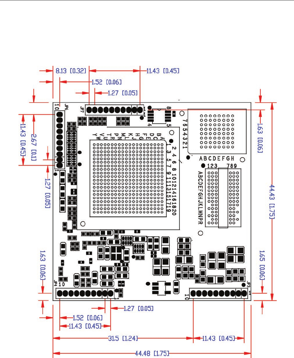
Dimensions
MiiNePort W1 Series Dimensions
Unit: mm (inch)
MiiNePort W1 Series Getting Started
2-3
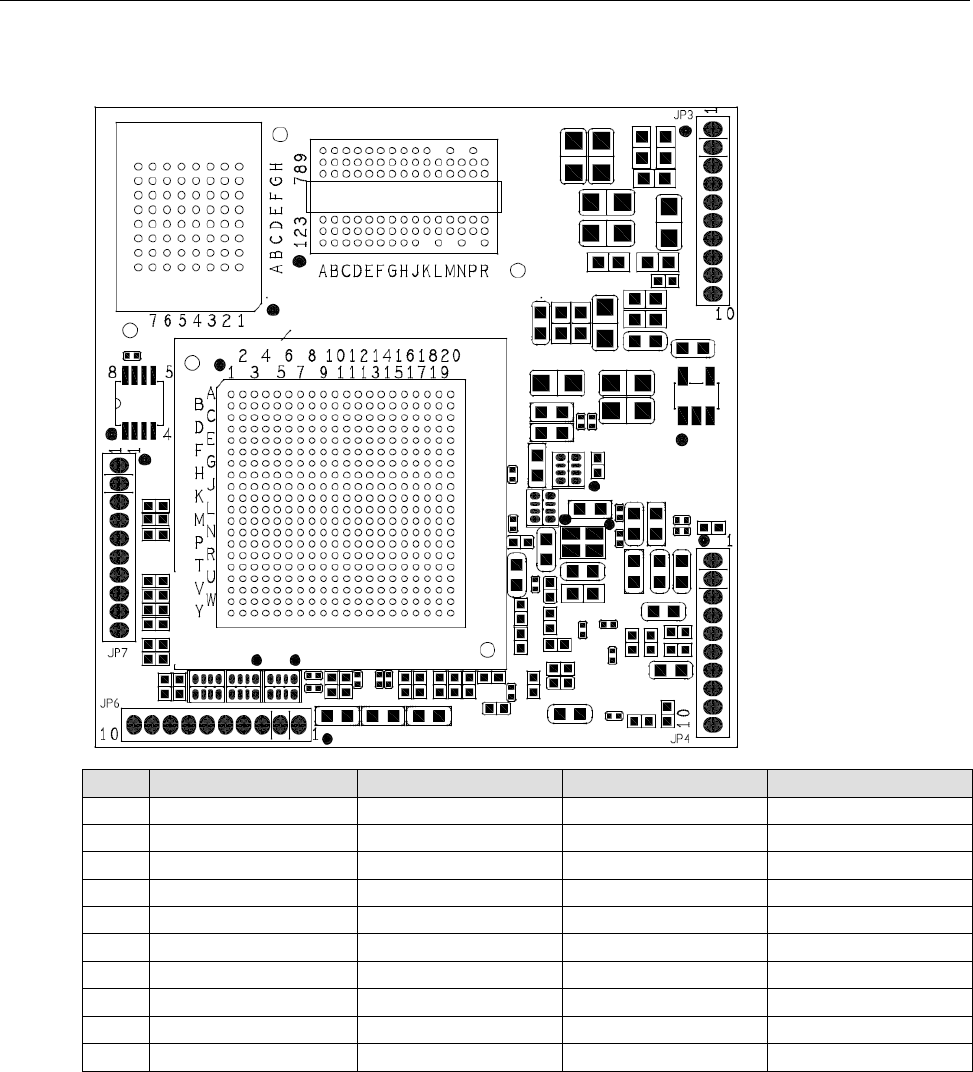
MiiNePort W1 Pin Assignments
Pin JP3 JP4 JP6 JP7
1 N.C. Eth_10M_LED PIO0 LTXD0
2 N.C. Eth_100M_LED PIO1 LRTS0
3
N.C.
Eth_Rx+
PIO2
LDTR0
4 RDY_LED Eth_Rx- PIO3 LRXD0
5 FLT_LED Eth_center_tap PIO4 LCTS0
6 HW_RESET Eth_center_tap PIO5 LDSR0
7 SW_RESET Eth_Tx+ PIO6 LDCD0
8 WLAN_Link Eth_Tx- PIO7 N.C.
9 Vin GND LTXD1 LCTS1
10 Vin GND LRTS1 LRXD1
MiiNePort W1 Series Getting Started
2-4
Wiring Requirements
ATTENTION
Before connecting the hardware, follow these important wiring safety
precautions:
Disconnect power source
Do not install or wire this unit or any attached devices with the power connected. Disconnect the power before
installation by removing the power cord before installing and/or wiring your unit.
Follow maximum current ra
tings
Calculate the maximum possible current in each power wire and common wire. Observe all electrical codes
dictating the maximum current allowable for each wire size.
If the current goes above the maximum ratings, the wiring could overheat, causing serious damage to your
equipment.
Use caution
- unit may get hot
The unit will generate heat during operation, and the casing may feel hot to the touch. Take care when handling
unit. Be sure to leave adequate space for ventilation.
The following guidelines will help ensure trouble-free signal communication:
• Use separate paths to route wiring for power and devices to avoid interference. Do not run signal or
communication wiring and power wiring in the same wire conduit. The rule of thumb is that wiring that
shares similar electrical characteristics can be bundled together.
• If power wiring and device wiring paths must cross, make sure the wires are perpendicular at the
intersection point.
• Keep input wiring and output wiring separate.
Label all wiring to each device in the system for easier testing and troubleshooting
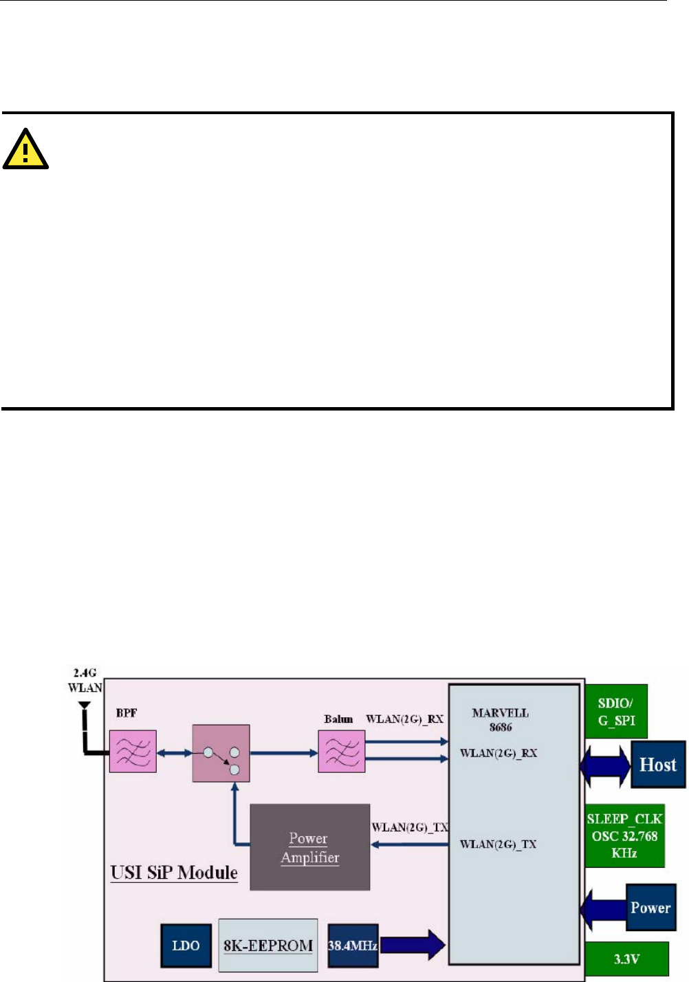
Black Diagram

MiiNePort W1 Series Getting Started
2-5
Hardware Installation
Steps for Installation
1. Attach the WLAN antenna to connect MiiNePort W1
2. Let MiiNePort W1 Module connect todevice.
Software Installation
After physically installing the MiiNePort W1, the module must be recognized on the new system board by the
following steps.
Step for Installation
1. Apply power to the system board.

MiiNePort W1 Series Compliance Notice
3-2
Federal Communications Commission
Statement
WARNING
This is a Class B product. In a domestic environment, this product may cause radio interference. The user may
be required to take appropriate measures.
This equipment has been tested and found to comply with the limits for a Class B digital device, pursuant to part 15 of the
FCC Rules. These limits are designed to provide reasonable protection against harmful interference in a residential
installation. This equipment generates, uses and can radiate radio frequency energy and, if not installed and used in
accordance with the instructions, may cause harmful interference to radio communications. However, there is no
guarantee that interference will not occur in a particular installation. If this equipment does cause harmful interference to
radio or television reception, which can be determined by turning the equipment off and on, the user is encouraged to try
to correct the interference by one or more of the following measures:
-Redirect or relocate the receiving antenna.
-Increase the distance between the equipment and receiver.
-Connect the equipment into an outlet on a circuit different from that to which the receiver is connected.
-Consult the dealer or an experienced radio/ TV technician for help.
CAUTION
Any changes or modifications not expressly approved by the grantee of this device could
void the user's
authority to operate the equipment.
Labeling Requirements
This device complies with Part 15 of the FCC Rules. Operation is subject to the following two conditions: (1) this device
may not cause harmful interference, and (2) this device must accept any interference received, including interference that
may cause undesired operation.
WARNING
RF e
xposure warning
This equipment must be installed and operated in accordance with provided instructions and the antenna(s)
used for this transmitter must be installed to provide a separation distance of at least
20
cm from all persons
and must not be co
-located or operating in conjunction with any other antenna or transmitter. End-
users and
installers must be provide with antenna installation instructions and transmitter operating conditions for
satisfying RF exposure compliance.
.
End Product Labeling
This transmitter module is authorized only for use in device where the antenna may be installed such that 20cm may be
maintained between the antenna and users. The final end product must be labeled in a visible area with the following:
Contains FCC ID: SLE-W1

MiiNePort W1 Series Compliance Notice
3-3
Information for OEM and Integrators
The following statement must be included with all versions of this document supplied to an
OEM or integrator, but should not be distributed to the end user.
1. This device is intended for OEM integrators only.
2. Please see the full Grant of Equipment document for other restrictions.
This radio transmitter FCCID: SLE-W1 has been approved by FCC to operate with the antenna types listed below with the
maximum permissible gain and required antenna impedance for each antenna type indicated. Antenna types not included
in this list, having a gain greater than the maximum gain indicated for that type, are strictly prohibited for use with this
device.
Antenna List
No. Manufacturer Model No. Antenna Type Peak Gain
1 WANSHIH ANT-WDB-O-2 BK Dipole Antenna 2 dBi for 2.4GHz
2 KINSUN ANT-WDB-ARM-02 Dipole Antenna 1.21 dBi for 2.4GHz
Note: The antenna connector is Reverse SMA type.