Moxa W2250 Wireless Serial Device Server User Manual UserMan
Moxa Inc. Wireless Serial Device Server UserMan
Moxa >
UserMan
Table of Contents
Chapter 1 Introduction......................................................................................1-1
Overview..........................................................
......................................1-2
Package
Checklist.........................................................
.........................1-2
Product
Features..........................................................
..........................1-2
Product
Specifications....................................................
........................1-3
Chapter 2 Getting Started.................................................................................2-1
Panel
Layout............................................................
..............................2-2
Connecting the
Hardware..........................................................
............2-3
Wiring Requirements................................................................................2-3
Connecting the Power...............................................................................2-3
Grounding NPort W2250/2150 Series...................................................................2-4
Connecting to the Network.......................................................................2-4
Connecting to a Serial Device...................................................................2-4
LED Indicators..........................................................................................2-4
Chapter 3 Initial IP Address Configuration.....................................................3-1
Installation Procedure for first tome
user.......................................................3-2
Factory Default IP
Address...........................................................
.........3-2
ARP...............................................................
.........................................3-2
Telnet
Console...........................................................
............................3-3
Serial Console (19200, n, 8,
1)..............................................................3-
5
Chapter 4 Choosing the Proper Operation Mode...........................................4-1
Overview..........................................................
......................................4-2
TCP Server
Mode..............................................................
....................4-2
TCP Client
Mode..............................................................
......................4-3
UDP
Mode..............................................................
................................4-3
Real COM
Mode..............................................................
.......................4-4
Chapter 5 Web Console Configuration............................................................5-1
Opening Your
Browser...........................................................
................5-2
Basic
Settings..........................................................
...............................5-4
Network
Settings..........................................................
..........................5-5
Serial Port
Settings..........................................................
..............................5-8
System
management........................................................
.......................5-11
Change
Password..........................................................
......................5-24
Load Factory
Default...........................................................
.................5-25
Save/Restart……………………………………………….
Chapter 6 Install and Configure Software .............................................6-1
Overview..........................................................
......................................6-2
Install NPort COM Mapping
Utility...........................................................
6-2
Install NPort Search Utility....................
Configuration NPort COM Mapping
Utility..........................................................................................6-4
Configuration NPort Search Utility................
Installation for real TTY and fixed TTY……………………………….
Upgrade Firmware....................................................................................6-8
Appendix A
Appendix B
Appendix C
Chapter 1 Introduction
Welcome to the NPort W2250/2150 Products of advanced serial device servers that make it easy
to control your serial devices. NPort W2150 include 1 port for RS-232/422/485, and NPort W2250
include 2 port for RS-232/422/485. The Wireless Serial Device Server is designed to easily
integrate any RS-232/422/485 serial device to a WLAN. It is ideal for use in environments where
LAN are not available and where serial devices are moved frequently.
The following topics are covered in this chapter:
Overview
Package Checklist
Product Features
Product Specifications
Overview
NPort W2250/2150 wireless serial device servers are designed to make your industrial serial
devices Internet ready instantly. The NPort W2250/2150 device servers makes them the ideal
choice for connecting your RS-232/422/485 serial devices—such as PLCs, meters, and
sensors—to an Wired Ethernet LAN and Wireless LAN, making it possible for your software to
access serial devices anywhere over a local LAN ’WLAN or the Internet. It is also useful ,when
serial devices are frequently moved
NPort W2250/2150 wireless serial device servers support automatic IP configuration protocols
(DHCP, BOOTP) and manual configuration via the handy web browser console. Both methods
ensure quick and effective installation. And with NPort Windows Driver Manager Utility, Port
Mapping is very convenient to configure.
An external antenna can increases the range of the wireless TCP/IP connection. Users can
move the adjustable antenna for maximum signal strength or can replace the antenna with
their own for additional flexibility and scalability. When a serial device is connected in a high
interference area, this feature is useful. Besides, we offer signal strength indicator on the front
label for your reference.
NPort W2250/2150 wireless serial device servers ensure the compatibility of network software
that uses a standard network API by providing TCP Server Mode, TCP Client Mode, and UDP
Mode. And the Real COM/TTY drivers, software that works with COM/TTY ports can be set up
to work over a TCP/IP network in no time. This excellent feature preserves your software
investment and lets you enjoy the benefits of networking your serial devices instantly.
The NPort W2250/2150 also provide additional features such as authentication ’IP filter ’WEP
supporting 64-bit and 128-bit encryption and SNMP support. It will make your management
easily
Package Checklist
NPort W2250/2150 are shipped with the following items:
Standard Accessories
NPort W2250 or W2150 x 1
Documentation & Software CD
RJ-45 to RJ-45 Ethernet cross cable
RJ-45 to DB9 male cable
Power adapter
Warranty booklet
Quick Installation Guide
Optional Accessories
DK-35A DIN-Rail Mounting Kit (35 mm)
CBL-RJ45M9-150 RJ45 (8-pin) to DB9 (M) cable, 150 cm
CBL-RJ45F9-150 RJ45 (8-pin) to DB9 (F) cable, 150 cm
CBL-RJ45M25-150 RJ45 (8-pin) to DB25 (M) cable, 150 cm
CBL-RJ45F25-150 RJ45 (8-pin) to DB25 (F) cable, 150 cm
NOTE: Notify your sales representative if any of the above items is missing or damaged.
Product Features
•Bring serial device to Wireless LAN network
•802.11b Wireless LAN, Compatible with 802.11g
• WEP supporting 64-bit and 128-bit encryption
• Password authentication and IP filter
• Ad-Hoc mode
•10/100M Ethernet for console
• 2/1 ports with RS-232/422/485, up to 230.4 Kbps
•Versatile socket operation modes, including TCP Server, TCP Client, and UDP
• Easy-to-use Windows Utility for mass installation
•Supports Windows, Linux Real COM driver
•LED for link power, and wireless bandwidth
Product Specifications
WLAN
Standard Compliance: 802.11b
Radio Frequency Type: DSSS
Tx Power: 15 dBm ± 2 (CH1~Ch13), 12dBm ± 2(CH14)
Rx Sensitivity: -84 dBm @11 Mbps, -87 dBm @5.5 Mbps,
-89 dBm @2 Mbps , -91 dBm @1 Mbps
Transmission Rate: 11 Mbps(max.) with auto fallback
(11, 5.5, 2, 1 Mbps)
Transmission distance: Up to 100 meters (@11 Mbps, in
open areas)
Security: WEP 64bit/128bit data encryption
Antenna Connector: Reverse SMA
Network Mode: Infrastructure mode, Ad-Hoc mode
LAN
Ethernet: 10/100Mbps, RJ45
Protection: Built-in 1.5KV magnetic isolation
Serial
No. of ports: 2 ports (NPort W2250), 1 port (NPort W2150)
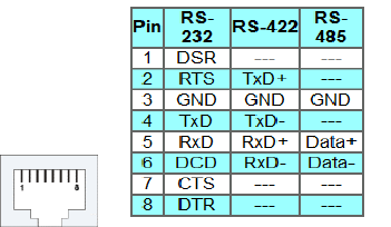
Interface: RS-232/422/485, RJ45 8 pins
Serial Communication Parameters
Parity: None, Even, Odd, Space, Mark
Data bits: 5, 6, 7, 8
Stop bits: 1, 1.5, 2
Flow control: RTS/CTS, XON/XOFF
Speed: 100bps to 230.4kbps
Console Ports
Ethernet x1, RS-232 console x1(Port 1)
Software Features
Protocol: ICMP, IP, TCP, UDP, DHCP, BOOTP, Telnet, DNS, SNMP, HTTP, SMTP
Utilities: Windows utility for Windows98/ME/2000/XP/2003
Configuration: Web browser, serial/telnet console, or Windows utility
Power Requirements
Power input: 12-48VDC
Power consumption: 250 mA @12V, 138 mA @24V
Mechanical Specifications
Material: Aluminum sheet metal (1mm)
Environmental
Operating Temperature: 0 to 55°C (32 to 131°F),
5 to 95% RH
Storage Temperature: -20 to 85°C (-4 to 185°F),
5 to 95% RH
Regulatory Approvals
EMC: FCC Class A, CE Class A
Safety: UL, CUL, TUV
RJ45 RS-232/422/485 port pin assignment
Dimensions
Chapter 2 Getting Started
This chapter includes information about installing NPort W2250/2150. The following topics are covered:
Panel Layout
Connecting the Hardware
Wiring Requirements
Connecting the Power
Connecting to the Network
Connecting to a Serial Device
LED Indicators
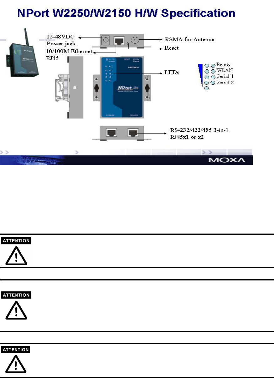
Panel Layout
Connecting the Hardware
This section describes how to connect NPort W2250/2150 Series to serial devices for first time
testing purposes. We cover Wiring Requirements, Connecting the Power, Connecting to the
Network, Connecting to a Serial Device, and LED Indicators.
Wiring Requirements
Safety First!
Be sure to disconnect the power cord before installing and/or wiring your device.
Wiring Caution!
Calculate the maximum possible current in each power wire and common wire. Observe all
electrical codes dictating the maximum current allowable for each wire size.
If the current goes above the maximum ratings, the wiring could overheat, causing serious
damage to your equipment.
Temperature Caution!
Please take care when handling device. When plugged in, device’s internal components generate
heat, and consequently the casing may feel hot to the touch.

You should also pay attention to the following items:
Use separate paths to route wiring for power and devices. If power wiring and
device wiring paths must cross, make sure the wires are perpendicular at the
intersection point.
NOTE: Do not run signal or communication wiring and power wiring in the
same wire conduit. To avoid interference, wires with different signal
characteristics should be routed separately.
You can use the type of signal transmitted through a wire to determine which
wires should be kept separate. The rule of thumb is that wiring that shares
similar electrical characteristics can be bundled together.
Keep input wiring and output wiring separate.
Where necessary, it is strongly advised that you label wiring to all devices in the system
Connecting the Power
Connect the 12-48 VDC power line with NPort W2250/2150’s terminal block. If the power is properly
supplied, the “Ready” LED will show a solid red color until the system is ready, at which time the
“Ready” LED will change to a green color.
Connecting to the Network
Connect one end of the Ethernet cable to NPort W2250/2150’s 10/100M Ethernet port and
the other end of the cable to the Ethernet network. If the cable is properly connected, NPort
W2250/2150 will indicate a valid connection to the Ethernet in the following ways:
The Ethernet LED maintains a solid green color when connected to a 100
Mbps Ethernet network.
The Ethernet LED maintains a solid orange color when connected to a 10
Mbps Ethernet network.
The Ethernet LED will flash when Ethernet packets are being transmitted or
received.
Connecting to a Serial Device
Connect the serial data cable between NPort W2250/2150 and the serial device. Serial data
cables are optional accessories for NPort W2250/2150. Refer to Chapter 1 under Optional
Accessories for information on the RJ45-to-DB25 and RJ45-to-DB9 cables.
LED Indicators
Type Color Meaning

Type Color Meaning
Red Steady On: Power is on and NPort is booting up.
Blinking: Indicates an LAN IP conflict, or DHCP or
BOOTP server did not respond properly.
Green Steady On: Power is on and NPort is functioning
normally.
Blinking: The device server has been located by
Administrator’s Location function.
Ready
Off Power is off, or power error condition exists.
WLAN Green On: Wireless Enable
Blinking: Indicates an WLAN IP conflict, or DHCP or
BOOTP server did not respond properly
Yellow 10M Ethernet connection.
Green 100M Ethernet connection.
10/100M Ethernet
Off Ethernet cable is disconnected, or has a short.
Yellow Serial port is receiving data.
Green Serial port is transmitting data.
P1, P2(W2250)
Off No data is being transmitted or received through the
serial port.
Signal Strength
Green Five LEDs represent WLAN signal strength of
20%~100%, in 20% scale. When WLAN link to the
access point, the last LED is on
Chapter 3 Initial IP Address Configuration
When setting up your NPort W2250/2150 for the first time, the first thing you should do is configure the IP
address. This chapter introduces the method to configure the device server’s IP address. Select one of the
initial IP Address configuration methods to configure NPort W2250/2150’s IP Address. For more details
about network settings, see the Network Settings section from Chapter 5, Web Console Configuration.
This chapter includes the following sections:
Installation Procedure for First Time User
Factory Default IP Address
ARP
Telnet Console
Serial Console (19200, n, 8, 1)
Installation Procedure for First Time User
STEP 1: After removing NPort W2250 from the box, the first thing using a cross-over Ethernet
cable connect directly to your computer’s Ethernet port.
STEP 2: Attaching the power adaptor
STEP 3: Connect NPort W2250’s serial port to a serial device.
STEP 4: Use Web console to configure the NPort W2250 via Ethernet port.
Note: Recommend to use web console for configuration. About how to use web console ,please
refer to Chapter 5.
Note: Only one Network Interface work at the same time.
If Ethernet Link up, Disable WLAN, Only Ethernet port can be used.
If Ethernet Link down, Disable Ethernet, Only WLAN can be used.
Factory Default IP Address
NPort W2250 products are configured with the following default IP address:
LAN: Default setting is static IP, 192.168.126.254/255.255.255.0, If Ethernet port cant' get IP
from DHCP, IP address return to 192.168.126.254/255.255.255.0
WLAN: Default setting is static IP, 192.168.127.254/255.255.255.0, If WLAN port cant' get
IP from DHCP, IP address return to
192.168.127.254/255.255.255.0
Only one interface allow to use DHCP settings
Note: If you have changed the IP address and forget it later. You can push the reset button of
the W2250 hardware, the IP will return to the default IP address.
ARP
You can make use of the ARP (Address Resolution Protocol) command to set up an IP address for
your NPort W2250/W2150. The ARP command tells your computer to associate the NPort
W2250/W2150’s MAC address with the intended IP address. You must then use Telnet to access
the NPort W2250/W2150, at which point the device server’s IP address will be reconfigured.
This function only apply to Ethernet port.
Take the following steps to use ARP to configure the IP address:
1. Obtain a valid IP address for your NPort W2250/W2150 from your network administrator.
2. Obtain NPort W2250/W2150’s MAC address from the label on its bottom panel.
3. Execute the ‘arp -s’ command from your computer’s MS-DOS prompt by typing:
arp –s 192.168.200.100 00-90-E8-xx-xx-xx
This is where 192.168.200.100 is the new IP address and 00-90-E8-xx-xx-xx is the MAC
address for your NPort W2250/W2150. You will need to change both numbers, as described
above in items 1 and 2.
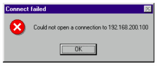
4. Next, execute a special Telnet command by typing: telnet 192.168.200.100 6000 After issuing
this command, a Connect failed message will appear, as shown here. After the NPort
W2250/W2150 reboots, its IP address should be updated to the new address, and you can
reconnect using either Telnet, Web, or Administrator to check that the update was successful.
Telnet Console
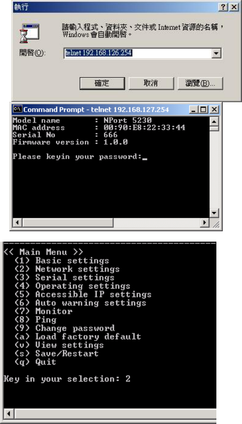
1. From the Windows desktop, click on Start and then select Run
2. Type telnet 192.168.126.254 (Default IP) in the Open text input box, and then click OK.
When the Telnet window opens, if you are prompted to input the Console password, input the
password and then press Enter.Note that this page will only appear if the NPort W2250 is
password protected.
3. Type 2 to select Network settings, and then press Enter
4. Type 1 to select IP address and then press Enter
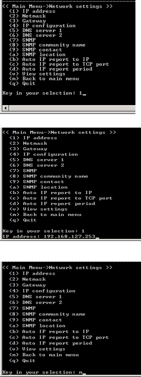
5. Use the Backspace key to erase the current IP address, type in the new IP address, and then
press Enter.
6. Type m and then press Enter to return to the main menu.
7. Type s and then press Enter to Save/Restart the system
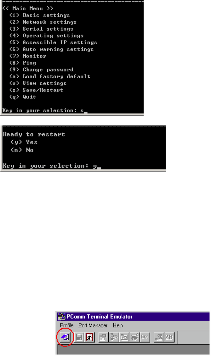
8. Type y and then press Enter to save the new IP address and restart NPort W2250/W2150.
Serial Console (19200, n, 8, 1)
You may use the RS-232 console port to set up the IP address for NPort W2250/W2150. We
suggest using PComm Terminal Emulator, which is available free of charge as part of the PComm
Lite program suite (found on the Software CD that comes with the product), to carry out the
installation procedure, although other similar utilities may also be used.
Before you start to configure the NPort W2250/W2150 via serial console, turn off the power and
connect the serial cable from NPort W2250/W2150 to your computer’s serial port.
1. Connect NPort W2250/W2150’s serial port 1 directly to your computer’s male RS-232 serial
port.
2. From the Windows desktop click on Start Programs PComm Lite Terminal
Emulator.
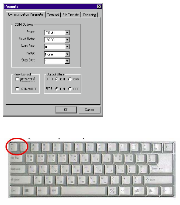
3. When the PComm Terminal Emulator window opens, first click on the Port Manager menu
item and select Open, or simply click on the Open icon.
4. The Property window opens automatically. From the Communication Parameter page,
select the appropriate COM port for the connection, COM1 in this example, and 19200 for
Baud Rate, 8 for Data Bits, None for Parity, and 1 for Stop Bits.
5. From the Property window’s Terminal page, select ANSI or VT100 for Terminal Type and
then click OK. If you select Dumb Terminal as the terminal type, some of the console
functions—especially the “Monitor” function—may not work properly.
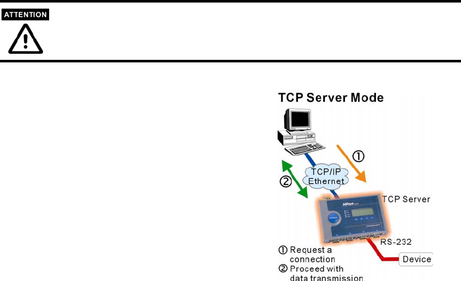
6. Press the “ ` ” key continuously and then power on the NPort W2250/W2150.
7. NPort W2250/W2150 will receive the “ ` ” string continuously and then auto switch from data
mode to console mode.
8. Input the password when prompted. Note that this page will only appear when the NPort
W2250/W2150 has been set up for password protection.
9.Start configuring the IP address under Network Settings. Refer to the Telnet Console section
for the rest of the IP settings.
Chapter 4 Choosing the Proper Operation Mode
In this section, we describe the various NPort 5200 operation modes. The options include an
operation mode that uses a driver installed on the host computer, and operation modes that rely
on TCP/IP socket programming concepts. After choosing the proper operation mode in this
chapter, refer to Chapter 5 for detailed configuration parameter definitions.
Overview
TCP Server Mode
TCP Client Mode
UDP Mode
Real COM Mode
Overview
NPort 5200 Serial Device Servers network-enable traditional RS-232/422/485 devices, in
which a Serial Device Server is a tiny computer equipped with a CPU, real-time OS, and
TCP/IP protocols that can bi-directionally translate data between the serial and Ethernet
formats. Your computer can access, manage, and configure remote facilities and equipment
over the Internet from anywhere in the world.
Traditional SCADA and data collection systems rely on serial ports (RS-232/422/485) to
collect data from various kinds of instruments. Since NPort 5200 Serial Device Servers
network-enable instruments equipped with an RS-232/422/485 communication port, your
SCADA and data collection system will be able to access all instruments connected to a
standard TCP/IP network, regardless of whether the devices are used locally or at a remote
site.
NPort 5200 is an external IP-based network device that allows you to expand the number of
serial ports for a host computer on demand. As long as your host computer supports the
TCP/IP protocol, you won’t be limited by the host computer’s bus limitation (such as ISA or
PCI), or lack of drivers for various operating systems.
In addition to providing socket access, NPort 5200 also comes with a Real COM/TTY driver
that transmits all serial signals intact. This means that your existing COM/TTY-based
software can be preserved, without needing to invest in additional software.
Three different Socket Modes are available: TCP Server, TCP Client, and UDP Server/Client.
The main difference between the TCP and UDP protocols is that TCP guarantees delivery of
data by requiring the recipient to send an acknowledgement to the sender. UDP does not
require this type of verification, making it possible to offer speedier delivery. UDP also
allows unicast or multicast of data to only one IP or groups of IP addresses.
Pictures in this Chapter will use NPort 5400 series as an example.
TCP Server Mode
In TCP Server mode, NPort 5200 is configured
with a unique IP:Port address on a TCP/IP
network. NPort 5200 waits passively to be
contacted by the host computer, allowing the host
computer to establish a connection with and get
data from the serial device. This operation mode
also supports up to 4 simultaneous connections, so
that multiple hosts can collect data from the same
serial device—at the same time.
As illustrated in the figure, data transmission
proceeds as follows:
1. The host requests a connection from the NPort
5200 configured for TCP Server Mode.
2. Once the connection is established, data can
be transmitted in both directions—from the
host to the NPort 5200, and from the NPort
5200 to the host.
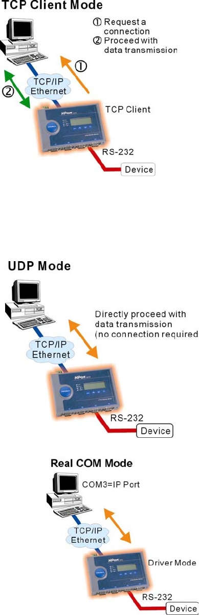
TCP Client Mode
In TCP Client mode, NPort 5200 can
actively establish a TCP connection to a
pre-defined host computer when serial data
arrives.
After the data has been transferred, NPort
5200 can automatically disconnect from the
host computer by using the TCP alive
check time or Inactivity time settings.
Refer to Chapter 5 for more details.
As illustrated in the figure, data
transmission proceeds as follows:
1. The NPort 5200 configured for TCP
Client Mode requests a connection
from the host.
2. Once the connection is established,
data can be transmitted in both
directions—from the host to the NPort
5200, and from the NPort 5200 to the
host.
UDP Mode
Compared to TCP communication, UDP is
faster and more efficient. In UDP mode, you
can unicast or multicast data from the serial
device to one or multiple host computers,
and the serial device can also receive data
from one or multiple host computers, making
this mode ideal for message display
applications.
Real COM Mode
NPort 5200 comes equipped with COM
drivers that work with Windows
95/98/ME/NT/2000/XP systems, and also
TTY drivers for Linux systems. The driver
establishes a transparent connection
between host and serial device by mapping
the IP:Port of the NPort 5200’s serial port
to a local COM/TTY port on the host
computer.

One of the major conveniences of using Real COM Mode is that Real COM Mode allows
users to continue using RS-232/422/485 serial communications software that was written for
pure serial communications applications. The driver intercepts data sent to the host’s COM
port, packs it into a TCP/IP packet, and then redirects it through the host’s Ethernet card. At
the other end of the connection, the NPort 5200 accepts the Ethernet frame, unpacks the
TCP/IP packet, and then transparently sends it to the appropriate serial device attached to one
of the NPort 5200’s serial ports.
Real COM Mode allows several hosts to have access control of the same NPort 5200. The driver
that comes with your NPort 5200 controls host access to attached serial devices by checking the
host’s IP address. Refer to Accessible IP Settings in Chapter 5 for more details.
Chapter 5 Web Console Configuration
The Web Console is the most user-friendly method available to configure NPort 5200 Series. This
chapter introduces the Web Console function groups and function definitions.
Opening Your Browser
Basic Settings
Network Settings
WLAN Configuration
Serial Port Settings
System Management
Change Password
Load Factory Default
Save/Restart
Opening Your Browser
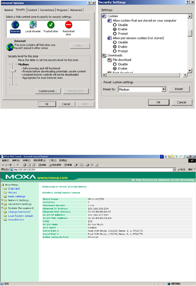
1. Open your browser with the cookie function enabled. (To enable your browser for cookies,
right click on your desktop Internet Explorer icon, select Properties, click on the Security tab,
and then select the three Enable options as shown in the figure below.)
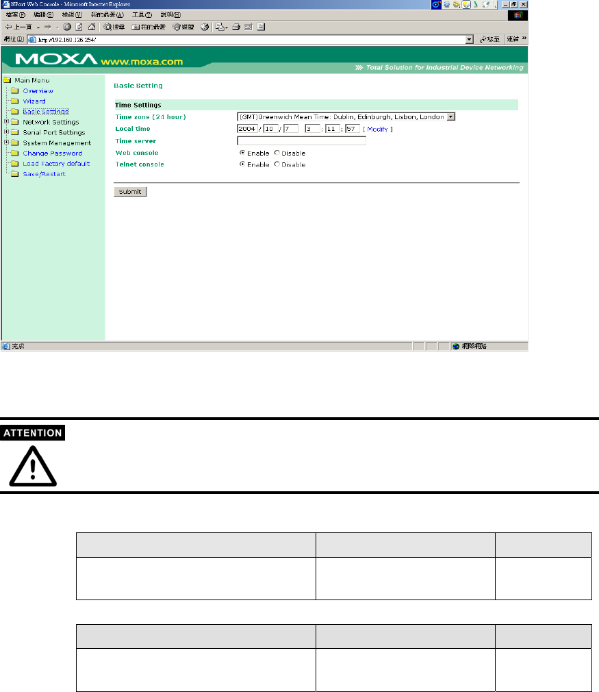
2. Type 192.168.126.254(Default IP) in the Address input box (use the correct IP address if
different from the default), and then press Enter.
3. Input the password if prompted. The password will be transmitted with MD5 encryption over
the Ethernet. Note that you will not be prompted to enter the password if the NPort 5200 is not
currently password protected.
4. The NPort 5200 homepage will open. On this page, you can see a brief description of the Web
Console’s nine function groups.

If you can’t remember the password, the ONLY way to start configuring NPort 5200 is to load
factory defaults by using the Reset button located near the NPort 5200’s RJ45 Ethernet port.
Remember to use Windows Administrator to export the configuration file when you have finished
the configuration. After using the Reset button to load factory defaults, your configuration can be
easily reloaded into NPort 5200 by using the Windows Administrator Import function.
If you use other web browsers, remember to Enable the functions to “allow cookies that are
stored on your computer” or “allow per-session cookies.”
NPort 5200 uses cookies only for “password” transmission.
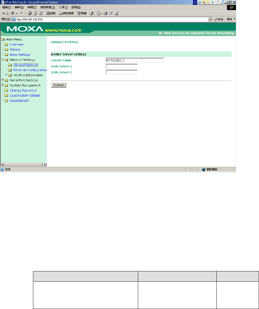
Basic Settings
Time
NPort 5200 has a built-in Real-Time Clock for time calibration functions. Functions such as
Auto warning “Email” or “SNMP Trap” can add real-time information to their messages.
First time users should select the time zone first. The Console will display the “real time”
according to the time zone compared to GMT.
If you would like to modify the real time clock, select “Local time.” NPort 5200’s firmware will
modify the GMT time according to the Time Zone.
Time zone
Setting Factory Default Necessity
User selectable time zone GMT (Greenwich Mean
Time) Optional
Local time
Setting Factory Default Necessity
User adjustable time
(1900/1/1-2037/12/31)
GMT (Greenwich Mean
Time) Optional
Click on the Modify button to open the
Modify time settings window to input the
correct local time.

Time server
Setting Factory Default Necessity
IP Address or Domain Name
(E.g., 192.168.1.1,
time.stdtime.gov.tw, or
time.nist.gov)
None Optional
NPort 5200 uses SNTP (RFC-1769) for auto time calibration.
Input the correct “Time server” IP address or domain name. Once NPort 5200 is configured
with the correct Time server address, NPort 5200 will request time information from the
“Time server” every 10 minutes.
Web/Telnet Console
The “Disable” option for “Web Console” and “Telnet Console” is included for security reasons. In
some cases, you may want to Disable one or both of these console utilities as an extra precaution
to prevent unauthorized users from accessing your NPort 5200. The factory default for both Web
console and Telnet console is Enable.
Setting Factory Default Necessity
Enable or Disable Enable Required
Network Settings
General Setting
Click “General Setting” option ,you can entry the server name and DNS server .
When the user wants to visit a particular website, the computer asks a Domain Name System
(DNS) server for the website’s correct IP address, and then the computer uses the response to
connect to the web server. DNS is the way that Internet domain names are identified and
translated into IP addresses. A domain name is an alphanumeric name, such as moxa.com, that it
is usually easier to remember. A DNS server is a host that translates this kind of text-based
domain name into the numeric IP address used to establish a TCP/IP connection.
In order to use NPort 5200’s DNS feature, you need to configure the DNS server. Doing so allows
NPort 5200 to use a host’s domain name to access the host. NPort 5200 provides DNS server 1
and DNS server 2 configuration items to configure the IP address of the DNS server. DNS Server
2 is included for use when DNS sever 1 is unavailable.
.
DNS server 1 / DNS server 2
Setting Factory Default Necessity
E.g., 192.168.1.1
(IP addresses of the form x.x.x.0
and x.x.x.255 are invalid.)
None Optional
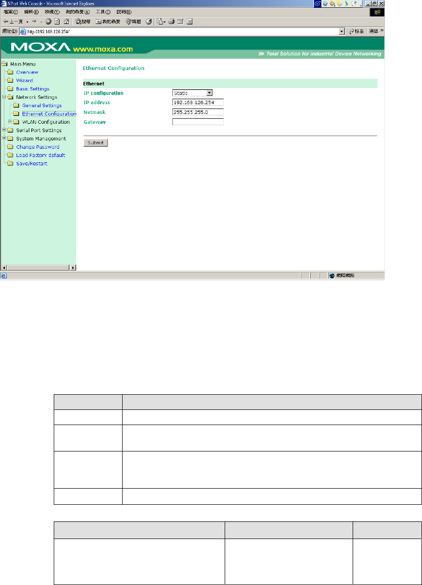
Ethernet Configuration
You must assign a valid IP address to NPort 5200 before it will work in your network environment.
Your network system administrator should provide you with an IP address and related settings for
your network. The IP address must be unique within the network (otherwise, NPort 5200 will not
have a valid connection to the network). First time users can refer to Chapter 3, “Initial IP Address
Configuration,” for more information.
You can choose from four possible “IP configuration” modes—Static, DHCP, DHCP/BOOTP, and
BOOTP—located under the web console screen’s IP configuration drop-down box.
Method Function Definition
Static User defined IP address, Netmask, Gateway.
DHCP DHCP Server assigned IP address, Netmask, Gateway, DNS, and Time
Server
DHCP/BOOTP DHCP Server assigned IP address, Netmask, Gateway, DNS, and Time
Server, or BOOTP Server assigned IP address (if the DHCP Server does not
respond)
BOOTP BOOTP Server assigns IP address
IP Address
Setting Factory Default Necessity
E.g., 192.168.1.1
(IP addresses of the form x.x.x.0
and x.x.x.255 are invalid.)
192.168.126.254 Required
An IP address is a number assigned to a network device (such as a computer) as a permanent

address on the network. Computers use the IP address to identify and talk to each other over the
network. Choose a proper IP address which is unique and valid in your network environment.
Netmask
Setting Factory Default Necessity
E.g., 255.255.255.0 255.255.255.0 Required
A subnet mask represents all of the network hosts at one geographic location, in one building, or
on the same local area network. When a packet is sent out over the network, the NPort 5200 will
use the subnet mask to check whether the desired TCP/IP host specified in the packet is on the
local network segment. If the address is on the same network segment as the NPort 5200, a
connection is established directly from the NPort 5200. Otherwise, the connection is established
through the given default gateway.
Gateway
Setting Factory Default Necessity
E.g., 192.168.1.1 None Optional
A gateway is a network gateway that acts as an entrance to another network. Usually, the
computers that control traffic within the network or at the local Internet service provider are
gateway nodes. NPort 5200 needs to know the IP address of the default gateway computer in
order to communicate with the hosts outside the local network environment. For correct gateway
IP address information, consult the network administrator.
IP configuration
Setting Factory Default Necessity
Static
DHCP
DHCP/BOOTP
BOOTP
Static Required
In Dynamic IP environments, the firmware will retry 3 times every 30 seconds until network
settings are assigned by the DHCP or BOOTP server. The Timeout for each try increases from 1
second, to 3 seconds, to 5 seconds.
If the DHCP/BOOTP Server is unavailable, the firmware will use the default IP address
(192.168.126.254), Netmask, and Gateway for IP settings.

WLAN Configuration
WLAN Configuration -> WLAN
The NPort supports IEEE 802.11b wireless network interface.
The supported IP configurations are static and dynamic (BOOTP , DHCP or BOOTP+DHCP ),
depending on users’ network environment. Users can setup the IP configuration via the serial
console, or the Web/Telnet consoles through Ethernet interface.
WLAN Mode :
<Ad-Hoc Mode>

In the above example, two NPort device have established an Ad-Hoc peer-to-peer
relationship. They communicate directly to each other’s serial devices without AP.
<Infrastructure Mode>
In the above example, the NPort device communicates with host computer via the
AP. The host computer is connected via an Ethernet connection to the AP. As such, the NPort
device and the host computer communicate directly and can transfer information to serial devices.
SSID:
Enter the name of the wireless network (SSID). The W2250/2150 connects to this wireless
network.
Channel:
Select from the pull down menu the radio channel for wireless network. In infrastructure mode, AP
will specify channel automatically. In Ad-hoc mode, user can specify channel by self.
If you want to change the WLAN IP address quickly, you can click the Wizard to configure.
WLAN Configuration -> Security
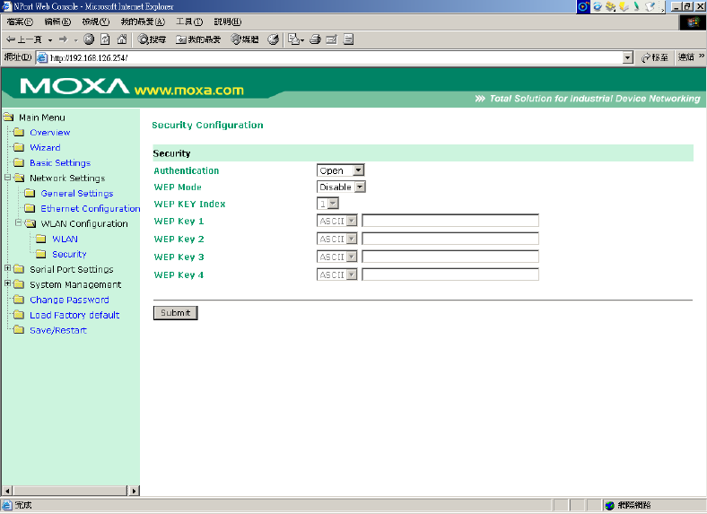
The wireless network interface supports data encryption (WEP, 64 or 128 bits) and authentication
(Open or Shared authentication).
Autherntication: Select an authentication scheme from the pull down menu: Open or Shared. Selecting
Shared requires manually entering the authentication key.
WEP Mode: enable WEP ,data packet will be encrypted before send .you can select 64 bit or 128
bit .By default, WEP Mode is disabled.
WEP Key format: There are two formats for selection, ASCII or HEX。
WEP Key1~ WEP Key4:There are four WEP Key to prevent data from steal.The setting of WEP
Key must be the same as AP.
Serial Port Settings
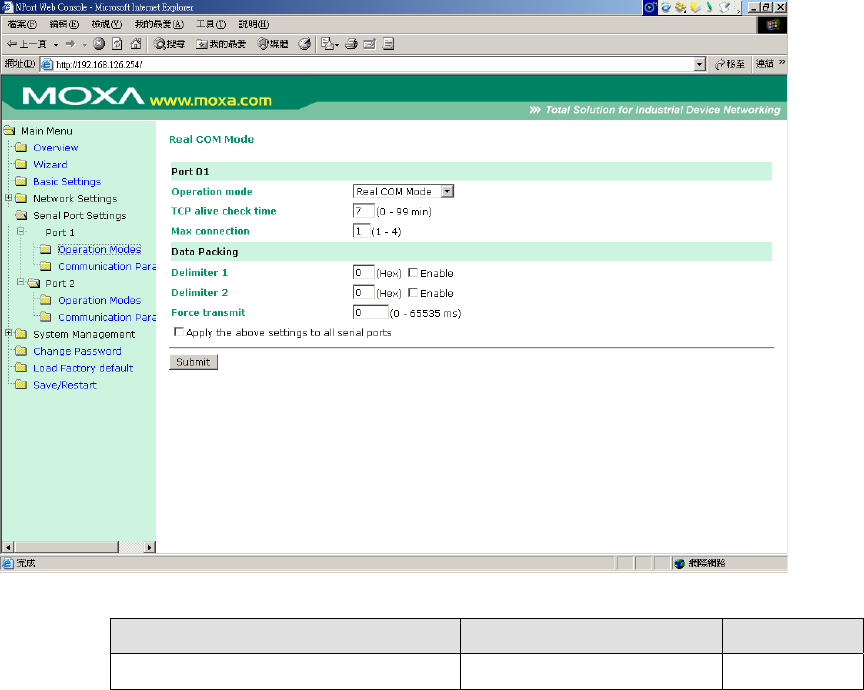
Serial Port Settings -> Operation Mode
Real COM Mode
TCP alive check time
Setting Factory Default Necessity
0 to 99 min 7 min Optional
0 min: TCP connection is not closed due to an idle TCP connection.
1 to 99 min: NPort 5200 automatically closes the TCP connection if there is no TCP activity
for the given time. After the connection is closed, NPort 5200 starts listening for another
Real COM driver connection from another host.
Max connection
Setting Factory Default Necessity
1, 2, 3, 4 1 Required
Max connection is usually used when the user needs to receive data from different hosts
simultaneously. The factory default is 1. In this case, only one specific host can access this
port of the NPort 5200, and the Real COM driver on that host will have full control over the
port.
Max. connection 1:
Allows only 1 host’s Real COM driver to open the specific NPort 5200 serial port.
Max connection 2 to 4:
Allows 2 to 4 host’s Real COM drivers to open the specific NPort 5200 serial port, at the
same time. When multiple hosts’ Real COM drivers open the serial port at the same time, the
COM driver only provides a pure data tunnel without control ability.
Application software that is based on the COM driver will receive a driver response of
“success” when the software uses any of the Win32 API functions. The firmware will only
send the data back to the driver on the host.
Data will be sent first-in-first-out when data comes into the NPort 5200 from the Ethernet
interface.
When Max connection is set to 2, 3, or 4, this means that NPort 5200 will be using a “multi
connection application” (i.e., 2, 3, or 4 hosts are allowed access to the port at the same time).
When using a multi connection application, NPort 5200 will use the serial communication
parameters set in the console. All of the hosts connected to that port must use the same serial
settings. If one of the hosts opens the COM port with parameters that are different from NPort
5200’s console setting, data communication may not work properly.
Delimiter 1
Setting Factory Default Necessity
00 to FF (hex) None Optional
Delimiter 2
Setting Factory Default Necessity
00 to FF (hex) None Optional
Once the NPort 5200 receives both delimiters through its serial port, it immediately packs all
data currently in its buffer and sends it to the NPort 5200’s Ethernet port.
Delimiter 2 is optional. If left blank, then Delimiter 1 alone trips clearing of the buffer. If the size
of the serial data received is greater than 1 KB, the NPort 5200 will automatically pack the data
and send it to the Ethernet. However, to use the delimiter function, you must at least enable
Delimiter 1. If Delimiter 1 is left blank and Delimiter 2 is enabled, the delimiter function will not
work properly.

Force transmit
Setting Factory Default Necessity
0 to 65535 ms 0 ms Optional
0: Disable the force transmit timeout.
1 to 65535: Forces the NPort 5200’s TCP/IP protocol software to try to pack serial data
received during the specified time into the same data frame.
This parameter defines the time interval during which NPort 5200 fetches the serial data from
its internal buffer. If data is incoming through the serial port, NPort 5200 stores the data in
the internal buffer. NPort 5200 transmits data stored in the buffer via TCP/IP, but only if the
internal buffer is full or if the Force transmit time interval reaches the time specified under
Force transmit timeout.
The optimal Force transmit timeout depends on your application, but it must be at least larger
than one character interval within the specified baud rate. For example, assume that the serial
port is set to 1200 bps, 8 data bits, 1 stop bit, and no parity. In this case, the total number of
bits needed to send a character is 10 bits, and the time required to transfer one character is
( 10 (bits) / 1200 (bits/s) ) * 1000 (ms/s) = 8.3 ms.
Therefore, you should set Force transmit timeout to be larger than 8.3 ms, so in this case, it
must be greater than or equal to 10 ms.
If the user wants to send a series of characters in the same packet, the serial device attached
to NPort 5200 should send that series of characters during a time interval less than the Force
transmit timeout for NPort 5200, and the total length of data must be less than or equal to
NPort 5200’s internal buffer size. The serial communication buffer size for NPort 5200 is 1
KB per port.
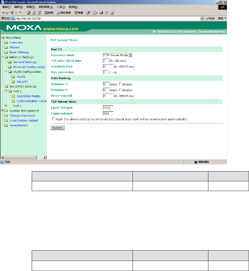
TCP Server Mode
TCP alive check time
Setting Factory Default Necessity
0 to 99 min 7 min Optional
0 min: TCP connection is not closed due to an idle TCP connection.
1 to 99 min: NPort 5200 automatically closes the TCP connection if there is no TCP activity
for the given time. After the connection is closed, NPort 5200 starts listening for another
host’s TCP connection.
Inactivity time
Setting Factory Default Necessity
0 to 65535 ms 0 ms Optional
0 ms: TCP connection is not closed due to an idle serial line.
0-65535 ms: NPort 5200 automatically closes the TCP connection if there is no serial data
activity for the given time. After the connection is closed, NPort 5200 starts listening for
another host’s TCP connection.
This parameter defines the maintenance status as Closed or Listen for the TCP connection.
The connection is closed if there is no incoming or outgoing data through the serial port
during the specific Inactivity time.
If the Inactivity time is set to 0, the current TCP connection is kept active until a connection
close request is received. Although Inactivity time is disabled, the NPort 5200 will check the
connection status between the NPort 5200 and remote host by sending “keep alive” packets
periodically. If the remote host does not respond to the packet, NPort 5200 assumes that the
connection was closed down unintentionally. NPort 5200 will then force the existing TCP
connection to close.
The Inactivity time should at least be set larger than that of Force transmit timeout. To prevent
the unintended loss of data due to the session being disconnected, it is highly recommended that
this value is set large enough so that the intended data transfer is completed.
Max connection
Setting Factory Default Necessity
1, 2, 3, 4 1 Required
Max connection is usually used when the user needs to receive data from different hosts
simultaneously. The factory default only allows 1 connection at a time.
Max. Connection 1:
NPort 5200 only allows 1 host to open the TCP connection to the specific serial port.
Max Connection 2 to 4:
Allows 2 to 4 host’s TCP connection request to open this NPort 5200 serial port, at the same
time. When multiple hosts establish a TCP connection to the specific serial port at the same
time, NPort 5200 will duplicate the serial data and transmit to all of the hosts. Ethernet data
is sent on a first-in-first-out basis to the serial port when data comes into NPort 5200 from
the Ethernet interface.
Delimiter 1
Setting Factory Default Necessity
00 to FF None Optional
Delimiter 2
Setting Factory Default Necessity
00 to FF None Optional
Once the NPort 5200 receives both delimiters through its serial port, it immediately packs all
data currently in its buffer and sends it out the NPort 5200’s Ethernet port.
Delimiter 2 is optional. If left blank, then Delimiter 1 alone trips clearing of the buffer. If the size
of the serial data received is greater than 1 KB, the NPort 5200 will automatically pack the data
and send it to the Ethernet. However, to use the delimiter function, you must at least enable
Delimiter 1. If Delimiter 1 is left blank and Delimiter 2 is enabled, the delimiter function will not
work properly.
Force transmit
Setting Factory Default Necessity
0 to 65535 ms 0 ms Optional
0: Disable the force transmit timeout.
1 to 65535: Forces the NPort 5200’s TCP/IP protocol software to try to pack serial data
received during the specified time into the same data frame.
This parameter defines the time interval during which NPort 5200 fetches the serial data from
its internal buffer. If data is incoming through the serial port, NPort 5200 stores the data in

the internal buffer. NPort 5200 transmits data stored in the buffer via TCP/IP, but only if the
internal buffer is full or if the Force transmit time interval reaches the time specified under
Force transmit timeout.
The optimal Force transmit timeout depends on your application, but it must be at least larger
than one character interval within the specified baud rate. For example, assume that the serial
port is set to 1200 bps, 8 data bits, 1 stop bit, and no parity. In this case, the total number of
bits needed to send a character is 10 bits, and the time required to transfer one character is
( 10 (bits) / 1200 (bits/s) ) * 1000 (ms/s) = 8.3 ms.
Therefore, you should set Force transmit timeout to be larger than 8.3 ms, so in this case, it
must be greater than or equal to 10 ms.
If the user wants to send a series of characters in the same packet, the serial device attached
to NPort 5200 should send that series of characters during a time interval less than the Force
transmit timeout for NPort 5200, and the total length of data must be less than or equal to
NPort 5200’s internal buffer size. The serial communication buffer size for NPort 5200 is 1
KB per port.
Local TCP port
Setting Factory Default Necessity
1 to 65535 4001 Required
The”Local TCP port” is the TCP port that NPort 5200 uses to listen to connections, and that
other devices must use to contact NPort 5200. To avoid conflicts with well known TCP ports,
the default is set to 4001.
Command port
Setting Factory Default Necessity
1 to 65535 966 Optional
The “Command port” is a listen TCP port for IP-Serial Lib commands from the host. In order
to prevent a TCP port conflict with other applications, the user can set the Command port to
another port if needed. IP-Serial Lib will automatically check the Command Port on NPort
5200 so that the user does not need to configure the program.
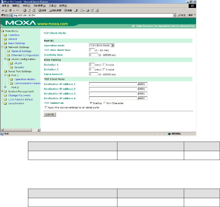
TCP Client Mode
TCP alive check time
Setting Factory Default Necessity
0 to 99 min 7 min Optional
0 min: TCP connection is not closed due to an idle TCP connection.
1 to 99 min: NPort 5200 automatically closes the TCP connection if there is no TCP activity
for the given time.
Inactivity time
Setting Factory Default Necessity
0 to 65535 ms 0 ms Optional
0 ms: TCP connection is not closed due to an idle serial line.
0-65535 ms: NPort 5200 automatically closes the TCP connection if there is no serial data
activity for the given time.
This parameter defines the maintenance status as Closed or Listen for the TCP connection.
The connection is closed if there is no incoming or outgoing data through the serial port
during the specific Inactivity time.
If the Inactivity time is set to 0, the current TCP connection is kept active until a connection
close request is received. Although Inactivity time is disabled, the NPort 5200 will check the
connection status between the NPort 5200 and remote host by sending “keep alive” packets
periodically. If the remote host does not respond to the packet, NPort 5200 assumes that the
connection was closed down unintentionally. NPort 5200 will then force the existing TCP
connection to close.
The Inactivity time should at least be set larger than that of Force transmit timeout. To prevent
the unintended loss of data due to the session being disconnected, it is highly recommended that
this value is set large enough so that the intended data transfer is completed.
Inactivity time is ONLY active when “TCP connect on” is set to “Any character.”
Delimiter 1
Setting Factory Default Necessity
00 to FF (hex) None Optional
Delimiter 2
Setting Factory Default Necessity
00 to FF (hex) None Optional
Once the NPort 5200 receives both delimiters through its serial port, it immediately packs all
data currently in its buffer and sends it to the NPort 5200’s Ethernet port.
Delimiter 2 is optional. If left blank, then Delimiter 1 alone trips clearing of the buffer. If the size
of the serial data received is greater than 1 KB, the NPort 5200 will automatically pack the data
and send it to the Ethernet. However, to use the delimiter function, you must at least enable
Delimiter 1. If Delimiter 1 is left blank and Delimiter 2 is enabled, the delimiter function will not
work properly.
Force transmit
Setting Factory Default Necessity
0 to 65535 ms 0 ms Optional
0: Disable the force transmit timeout.
1 to 65535: Forces the NPort 5200’s TCP/IP protocol software to try to pack serial data
received during the specified time into the same data frame.
This parameter defines the time interval during which NPort 5200 fetches the serial data from
its internal buffer. If data is incoming through the serial port, NPort 5200 stores the data in
the internal buffer. NPort 5200 transmits data stored in the buffer via TCP/IP, but only if the
internal buffer is full or if the Force transmit time interval reaches the time specified under
Force transmit timeout.
The optimal Force transmit timeout depends on your application, but it must be at least larger
than one character interval within the specified baud rate. For example, assume that the serial
port is set to 1200 bps, 8 data bits, 1 stop bit, and no parity. In this case, the total number of
bits needed to send a character is 10 bits, and the time required to transfer one character is
( 10 (bits) / 1200 (bits/s) ) * 1000 (ms/s) = 8.3 ms.
Therefore, you should set Force transmit timeout to be larger than 8.3 ms, so in this case, it
must be greater than or equal to 10 ms.
If the user wants to send a series of characters in the same packet, the serial device attached
to NPort 5200 should send that series of characters during a time interval less than the Force
transmit timeout for NPort 5200, and the total length of data must be less than or equal to
NPort 5200’s internal buffer size. The serial communication buffer size for NPort 5200 is 1
KB per port.
Destination IP address 1
Setting Factory Default Necessity
IP address or Domain Name
(E.g., 192.168.1.1)
None Required
Allows NPort 5200 to connect actively to the remote host whose IP address is set by this
parameter.
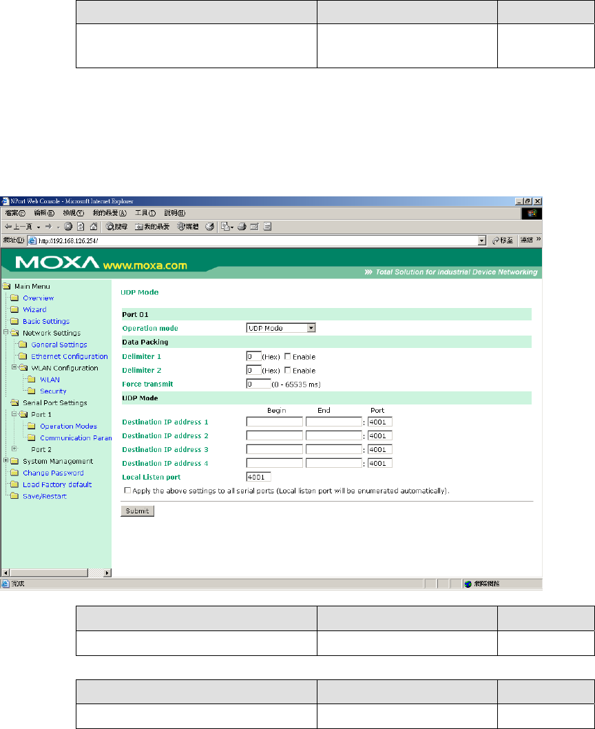
UDP Mode
Delimiter 1
Setting Factory Default Necessity
00 to FF None Optional
Delimiter 2
Setting Factory Default Necessity
00 to FF None Optional
Once the NPort 5200 receives both delimiters through its serial port, it immediately packs all
data currently in its buffer and sends it out the NPort 5200’s Ethernet port.
Delimiter 2 is optional. If left blank, then Delimiter 1 alone trips clearing of the buffer. If the size
of the serial data received is greater than 1 KB, the NPort 5200 will automatically pack the data
and send it to the Ethernet. However, to use the delimiter function, you must at least enable
Delimiter 1. If Delimiter 1 is left blank and Delimiter 2 is enabled, the delimiter function will not
work properly.
Force transmit
Setting Factory Default Necessity
0 to 65535 ms 0 ms Optional
0: Disable the force transmit timeout.
1 to 65535: Forces the NPort 5200’s TCP/IP protocol software to try to pack serial data
received during the specified time into the same data frame.
This parameter defines the time interval during which NPort 5200 fetches the serial data from
its internal buffer. If data is incoming through the serial port, NPort 5200 stores the data in
the internal buffer. NPort 5200 transmits data stored in the buffer via TCP/IP, but only if the
internal buffer is full or if the Force transmit time interval reaches the time specified under
Force transmit timeout.
The optimal Force transmit timeout depends on your application, but it must be at least larger
than one character interval within the specified baud rate. For example, assume that the serial
port is set to 1200 bps, 8 data bits, 1 stop bit, and no parity. In this case, the total number of
bits needed to send a character is 10 bits, and the time required to transfer one character is
( 10 (bits) / 1200 (bits/s) ) * 1000 (ms/s) = 8.3 ms.
Therefore, you should set Force transmit timeout to be larger than 8.3 ms, so in this case, it
must be greater than or equal to 10 ms.
If the user wants to send a series of characters in the same packet, the serial device attached
to NPort 5200 should send that series of characters during a time interval less than the Force
transmit timeout for NPort 5200, and the total length of data must be less than or equal to
NPort 5200’s internal buffer size. The serial communication buffer size for NPort 5200 is 1
KB per port.
Destination IP address 1
Setting Factory Default Necessity
Begin: Empty
End: Empty
IP address range
E.g., Begin: 192.168.1.1
End: 192.168.1.10 Port: 4001
Required
Destination IP address 2/3/4
Setting Factory Default Necessity
Begin: Empty
End: Empty
IP address range
E.g., Begin: 192.168.1.11
End: 192.168.1.20 Port: 4001
Optional
Local listen port
Setting Factory Default Necessity
1 to 65535 4001 Required
The UDP port that NPort 5200 listens to, and that other devices must use to contact NPort 5200.
To avoid conflicts with well known UDP ports, the default is set to 4001.
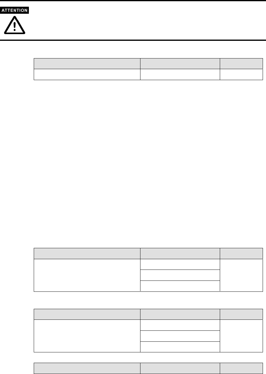
Serial Port Settings -> Communication Parameter
Port alias
Setting Factory Default Necessity
1 to 15 characters
(E.g., PLC-No.1)
None Optional
“Port alias” is included to allow easy identification of the serial devices that are connected to
NPort 5200’s serial port.
Serial Parameters
Check the serial communication parameters in your Serial Device’s user’s manual. You should set
up NPort 5200’s serial parameters with the same communication parameters used by your serial
devices.
Baud rate
Setting Factory Default Necessity
50 bps to 115.2 Kbps 115.2 Kbps Required

Data bits
Setting Factory Default Necessity
5, 6, 7, 8 8 Required
When the user sets Data bits to 5 bits, the Stop bits setting will automatically change to 1.5
bits.
Stop bits
Setting Factory Default Necessity
1, 2 1 Required
Stop bits will be set to 1.5 when Data bits is set to 5 bits.
Parity
Setting Factory Default Necessity
None, Even, Odd, Space, Mark None Required
Flow control
Setting Factory Default Necessity
None, RTS/CTS, DTR/DSR,
Xon/Xoff RTS/CTS Required
FIFO
Setting Factory Default Necessity
Enable, Disable Enable Required
NPort 5200’s serial ports provide a 16-byte FIFO both in the Tx and Rx directions. To
prevent data loss during communication, disable the FIFO setting when your serial device
does not have a FIFO.
Interface
Model Port Settings Factory Default Necessity
NPort
W2250 2 RS-232/422/485 RS-232 Required
NPort
W2150 1 RS-232/422/485 RS-232 Required
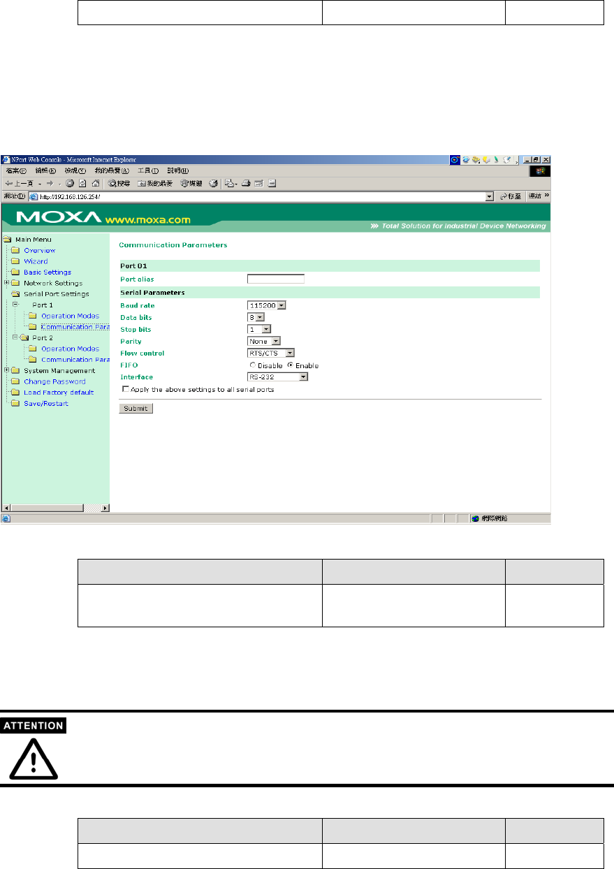
System Management
System Management -> Accessible IP Settings
NPort 5200 uses an IP address based filtering method to control access to itself.
Accessible IP Settings allows you to add or block remote host IP addresses to prevent
unauthorized access. Access to NPort 5200 is controlled by IP address. That is, if a
host’s IP address is in the accessible IP table, then the host will be allowed to access
the NPort 5200. You can allow one of the following cases by setting the parameter.
Only one host with a specific IP address can access the NPort 5200
Enter “IP address/255.255.255.255” (e.g.,
“192.168.1.1/255.255.255.255”).
Hosts on a specific subnet can access the NPort 5200
Enter “IP address/255.255.255.0” (e.g., “192.168.1.0/255.255.255.0”).
Any host can access the NPort 5200
Disable this function by un-checking the “Enable the accessible IP list”
checkbox. Refer to the following table for more configuration
examples.
Allowable Hosts Input format
Any host Disable
192.168.1.120 192.168.1.120 / 255.255.255.255
192.168.1.1 to 192.168.1.254 192.168.1.0 / 255.255.255.0
192.168.0.1 to 192.168.255.254 192.168.0.0 / 255.255.0.0
192.168.1.1 to 192.168.1.126 192.168.1.0 / 255.255.255.128
192.168.1.129 to 192.168.1.254 192.168.1.128 / 255.255.255.128
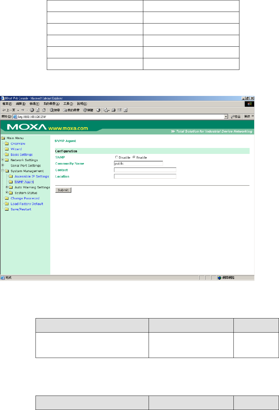
System Management -> SNMP Agent
If you want to enable SNMP Agent function , please select enable option.
And entry Community Name ,ex. ”public”.
Community name
Setting Factory Default Necessity
1 to 39 characters
(E.g., Support, 886-89191230 #300)
public Optional
A community name is a plain-text password mechanism that is used to
weakly authenticate queries to agents of managed network devices.
Contact
Setting Factory Default Necessity
1 to 39 characters
(E.g., Support, 886-89191230
#300)
None Optional
The SNMP contact information usually includes an emergency contact
name and telephone or pager number.
Location
Setting Factory Default Necessity
1 to 39 characters
(E.g., Floor 1, office 2)
None Optional
Specify the location string for SNMP agents such as NPort 5200. This string is
usually set to the street address where the NPort 5200 is physically located.
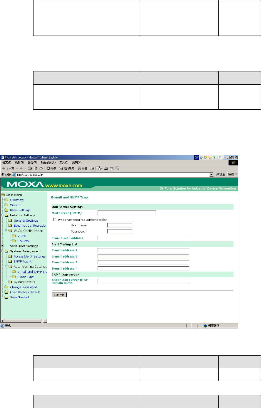
System Management -> Auto Warning Settings -> E-mail and SNMP Trap
Mail Server
Mail server
Setting Factory Default Necessity
IP Address or Domain Name None Optional
User name
Setting Factory Default Necessity

1 to 15 characters None Optional
Password
Setting Factory Default Necessity
1 to 15 characters None Optional
From E-mail address
Setting Factory Default Necessity
1 to 63 characters None Optional
E-mail address 1/2/3/4
Setting Factory Default Necessity
1 to 63 characters None Optional
Consult your Network Administrator or ISP for the proper mail server settings. The Auto warning
function may not work properly if it is not configured correctly. NPort W2250/W2150 SMTP
AUTH supports LOGIN, PLAIN, CRAM-MD5 (RFC 2554).
SNMP Trap Server
SNMP trap server IP or domain name
Setting Factory Default Necessity
IP address or Domain Name None Optional
System Management -> Auto Warning Settings -> Event Type
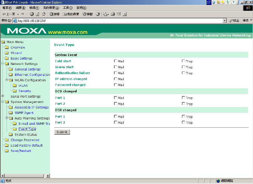
Cold start
This refers to starting the system from power off (contrast this with warm start). When
performing a cold start, NPort W2250/W2150 will automatically issue an Auto
warning message by e-mail, or send an SNMP trap after booting up.
Warm start
This refers to restarting the computer without turning the power off. When performing
a warm start, NPort W2250/W2150 will automatically send an e-mail, or send an
SNMP trap after rebooting.
Authentication failure
The user inputs a wrong password from the Console or Administrator. When
authentication failure occurs, NPort W2250/W2150 will immediately send an e-mail
or send an SNMP trap.
IP address changed
The user has changed NPort W2250/W2150’s IP address. When the IP address
changes, NPort W2250/W2150 will send an e-mail with the new IP address before
NPort W2250/W2150 reboots. If the NPort W2250/W2150 is unable to send an e-mail
message to the mail server within 15 seconds, NPort W2250/W2150 will reboot
anyway, and abort the e-mail auto warning.
Password changed
The user has changed NPort W2250/W2150’s password. When the password changes,

NPort W2250/W2150 will send an e-mail with the password changed notice before
NPort W2250/W2150 reboots. If the NPort W2250/W2150 is unable to send an e-mail
message to the mail server within 15 seconds, NPort W2250/W2150 will reboot
anyway, and abort the e-mail auto warning.
DCD changed
The DCD (Data Carrier Detect) signal has changed, also indicating that the modem
connection status has changed. For example, a DCD change to high also means
“Connected” between local modem and remote modem. If the DCD signal changes to
low, it also means that the connection line is down.
When the DCD changes, NPort W2250/2150 will immediately send an e-mail or send
an SNMP trap.
DSR changed
The DSR (Data Set Ready) signal has changed, also indicating that the data
communication equipment’s power is off. For example, a DSR change to high also
means that the DCE is powered ON. If the DSR signal changes to low, it also means
that the DCE is powered off.
When the DSR changes, NPort W2250/2150 will immediately send an e-mail or send
an SNMP trap.
Mail
Setting Factory Default Necessity
Enable, Disable Disable Optional
This feature helps the administrator manage how the NPort W2250/W2150 sends
e-mail to pre-defined e-mail boxes when the enabled events—such as Cold start,
Warm start, Authentication failure, etc.—occur. To configure this feature, click on the
Event Type Mail checkbox.
Trap
Setting Factory Default Necessity
Enable, Disable Disable Optional
This feature helps the administrator manage how the NPort W2250/W2150 sends
SNMP Trap to a pre-defined SNMP Trap server when the enabled events—such as
Cold start, Warm start, Authentication failure, etc.—occur. To configure this feature,
click on the Event Type Trap checkbox.
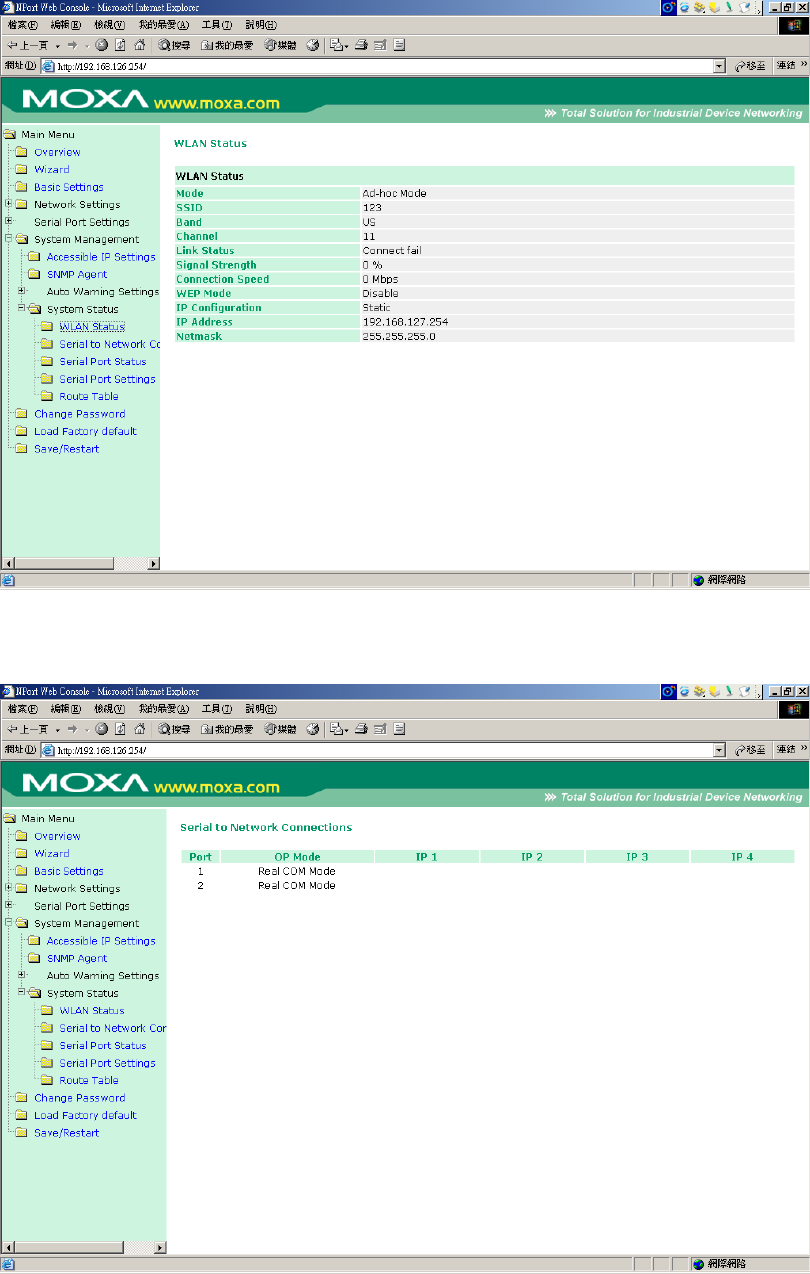
System Management -> System Status -> WLAN Status
You can check WLAN Mode,SSID,Channel,WEP Mode…etc.status.
System Management -> System Status -> Serial to Network Connections
You can check Network Operation Mode…etc.
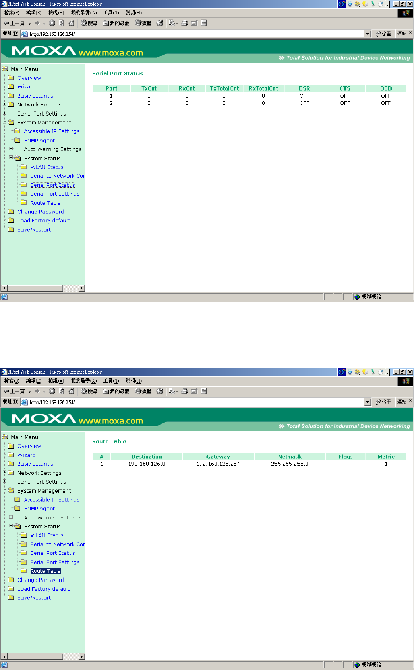
System Management -> System Status -> Serial Port Status
You can check Serial Port ,Tx ,Rx ,DSRCTS,DCD…etc.status.
System Management -> System Status -> Route Table
You can check Route Table status.
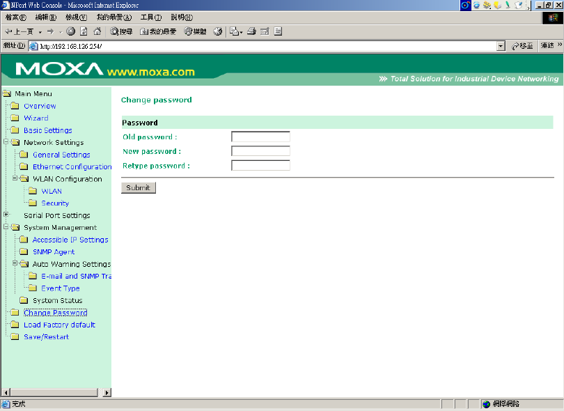
Change Password
Input the “Old password” and “New password” to change the password. Leave the
password boxes blank to erase the password. If the password is erased, then NPort
W2250/W2150 will not have password protection.
If you forget the password, the ONLY way to configure NPort W2250/W2150 is by using the
Reset button on NPort W2250/W2150’s casing to “Load Factory Default.”
Remember to export the configuration file using Windows Administrator when you finish the
configuration. By using the Import function of Windows Administrator, your configuration can
be re-loaded into NPort W2250/W2150 after using “Load Factory Default.” Refer to Chapter 6
for more details about the Export and Import function.
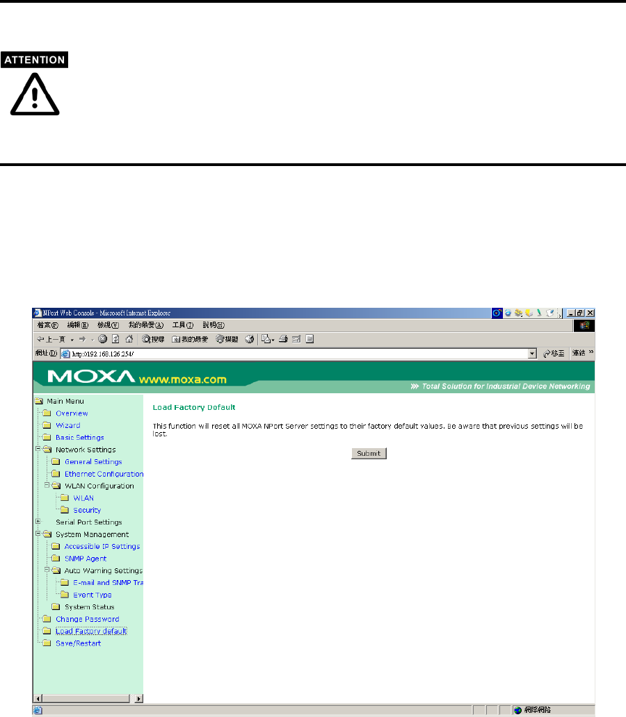
Load Factory Default
This function will reset all of NPort W2250/W2150’s settings to the factory default
values. Be aware that previous settings will be lost.
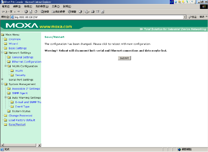
Save/Restart
After changed configuration ,you have to save and reboot with new configuration.
Chapter 6 Install and Configure Software
The following topics are covered in this chapter:
Overview
Install NPort COM Driver
Install NPort Search Utility
Configuration NPort COM Driver
Configuration NPort Search Utility
Installation for Real TTY and Fixed TTY
Upgrade Firmware
Overview
We understand the importance of software as the foundation of your application,
and with this in mind, we provide auto-run CD to let you easily install and
configure your NPort W 2250/2150 products . The auto-run CD include NPort
COM Driver , NPort Search Utility and Manual, allows COM mapping, and
provides broadcast search and firmware upgrade.
Install NPort COM Driver
Installing NPort COM Driver
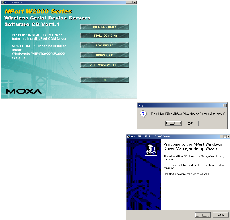
1. After insert the CD , screen will show auto-run
screen , then click the Installing NPort COM Driver
item.
2. Once the program starts running, click on
Yes to proceed.
3. Click on Next when the Welcome
window opens to proceed with the
installation.
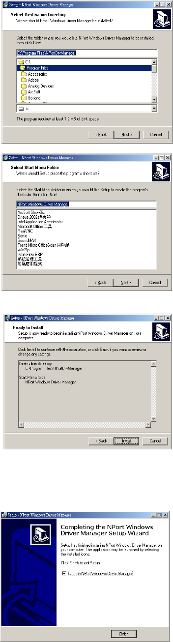
4. Click on Next to install program
files in the default directory, or
select an alternative location.
5. Click on Next to install the
program using the default
program name, or select a
different name.
6. Click on Install to proceed
with the installation.
7. The Installing window reports the progress of the installation.
8. Click on Finish to complete the
installation of NPort
W2250/W2150 NPort COM
MappingUtility.
Install NPort Search Utility
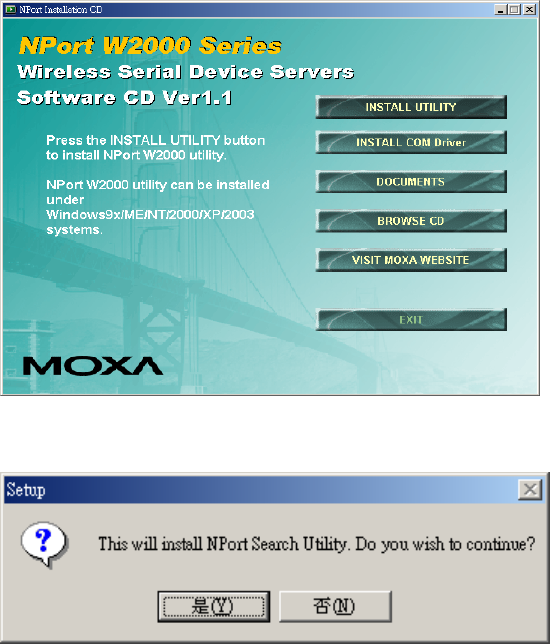
1. After insert the CD , screen will show auto-run , then click the Installing NPort
Search Utility item.
2. Once the program starts running, click on Ye s to proceed.
3. Click on Next when the Welcome window opens to proceed with the
installation.
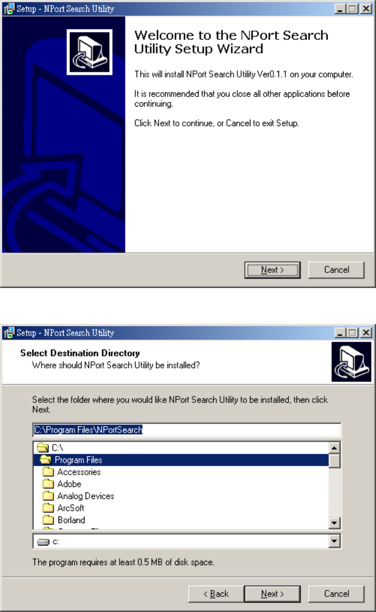
4. Click on Next to install program files in the default directory, or select an
alternative location.
5. Click on Next to install the program using the default program name, or select a
different name.
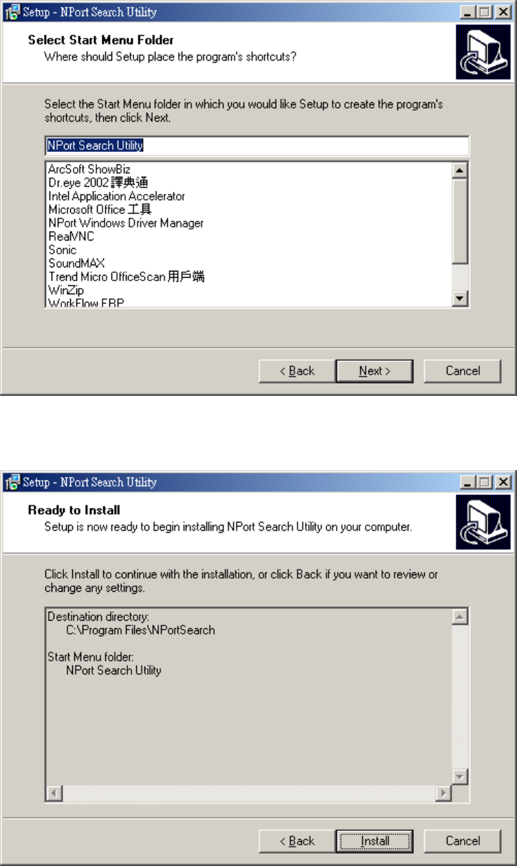
6. Click on Install to proceed with the installation.
7. The Installing window reports the progress of the installation.
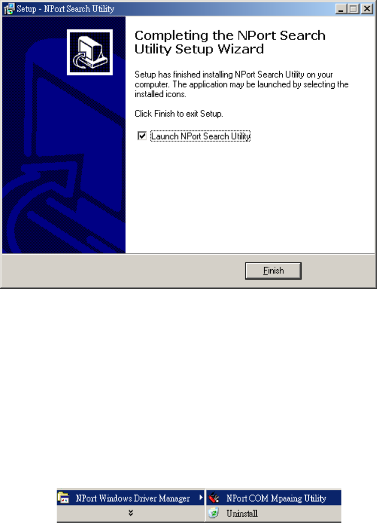
8. Click on Finish to complete the installation of NPort W2250/W2150 NPort
Search Utility.
Configuration COM Mapping
NPort COM Driver comes with Windows 98/ME/2000/XP/2003 Real
COM drivers. After you install NPort COM Driver, then you can set up
the NPort W2250/W2150’s serial port as your host’s remote COM port.
Use the following step to map COM ports:
1. Open the COM Mapping utility.
2.click “add” icon
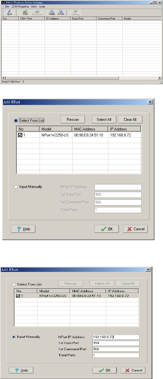
click “Rescan” for search NPort device .
3. you can also select “input manually” . Add the target to which you would
like to map COM ports.
4. Click “yes” to active the COM port, or you can select “apply”
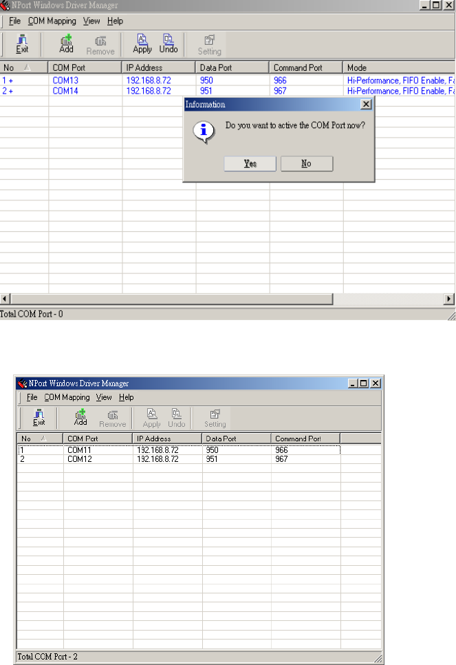
to active the COM port later. Active the COM port to save the
information in the host system registry. The host computer will
not have the ability to use the COM port until after Apply
Change is selected.
5. The word will be turned blue into black
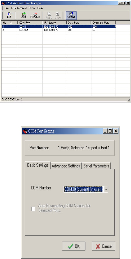
6. Select “COM Setting” to
modify COM No., default
setting, etc.
7. Select the COM No.
COM ports that are “In use” or
“Assigned” will also be indicated
in this drop-down list.
If you select multiple serial ports
or multiple NPort
W2250/W2150s, remember to
check the “Auto Enumerating”
function to use the COM No.
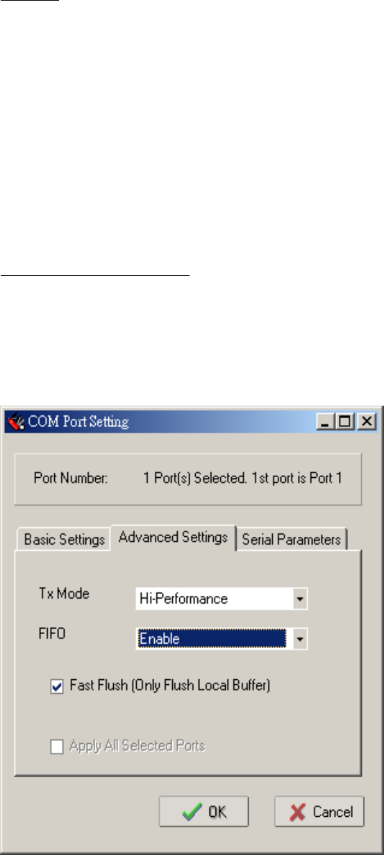
8. Advanced Setting
Tx Mode
Hi-performance mode is the default for Tx mode. If the driver
completes sending data out to the NPort W2250/W2150, the driver
will respond “Tx Empty” to the program.
Under classical mode, the driver will not notify the user’s program
that Tx is completed until all Tx data has been sent out from the
NPort W2250/W2150; this mode will cause lower throughput. If
you want to ensure that all data is sent out before further
processing, classical mode is recommended.
Enable/Disable Tx/Rx FIFO.
If disabled, NPort W2250/W2150 will send one byte each time
the Tx FIFO becomes empty; and an Rx interrupt will be generated
for each incoming byte. This will result in a faster response and
lower throughput. If you want to use XON/XOFF flow control, we
recommend setting FIFO to Disable.

Fast Flush (only flush local buffer)
1. We have added one optional Fast Flush function to Moxa new
NPort Real COM driver.
2. For some applications, the user’s program will use the Win32
“PurgeComm()” function before it reads or writes data. With our
design, after the program uses this Purge Comm() function, the
NPort driver will keep querying NPort’s firmware several times to
make sure there is really no data queued in the NPort firmware
buffer, rather than just flushing the local buffer. This kind of
design is used because of some special considerations. However, it
might take more time (about several hundred milliseconds) than a
native COM1, because it needs to work via Ethernet. That’s why
the native COM ports on the motherboard can work fast with this
function call, but NPort requires much more time. In order to
accommodate other applications that require a faster response
time, the new NPort driver implements a new “Fast Flush” option.
Note that by default, this function is disabled.
3. To begin with, make sure there are some “PurgeComm()”
functions being used in your application program. In this kind of
situation, you might find that your NPort exhibits a much poorer
operation performance than when using the native COM1 port.
Once you have enabled the “Fast Flush” function, you can check to
see if there has been an improvement in performance.
4. By default, the optional “Fast Flush” function is disabled. If you
would like to enable this function, double click on the COM ports
that are mapped to the NPort, and then select the “Fast Flush”
checkbox. You should find that when “Fast Flush” is enabled, the
NPort driver will work faster with “PurgeComm().”
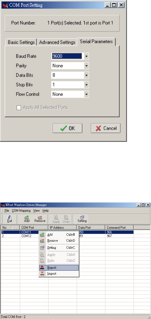
9. The Serial Parameter settings shown here are the default
settings when the NPort W2250/W2150 is powered on.
However, the program can redefine the serial parameters to
different values after the program opens the port via Win 32
API.
10. To save the configuration to a text file, select Export COM
Mapping. You will then be able to import this configuration file to
another host and use the same COM Mapping settings in the other host.
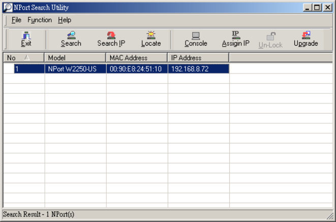
Configuration NPort Search Utility
The Broadcast Search function is used to locate all NPort
W2250/W2150s that are connected to the same LAN as
your computer. After locate NPort W2250/W2150s, you
can also change the IP address.
Since the Broadcast Search function searches by MAC
address and not IP address, all NPort W2250/W2150s
connected to the LAN will be located, regardless of
whether or not they are part of the same subnet as the host.
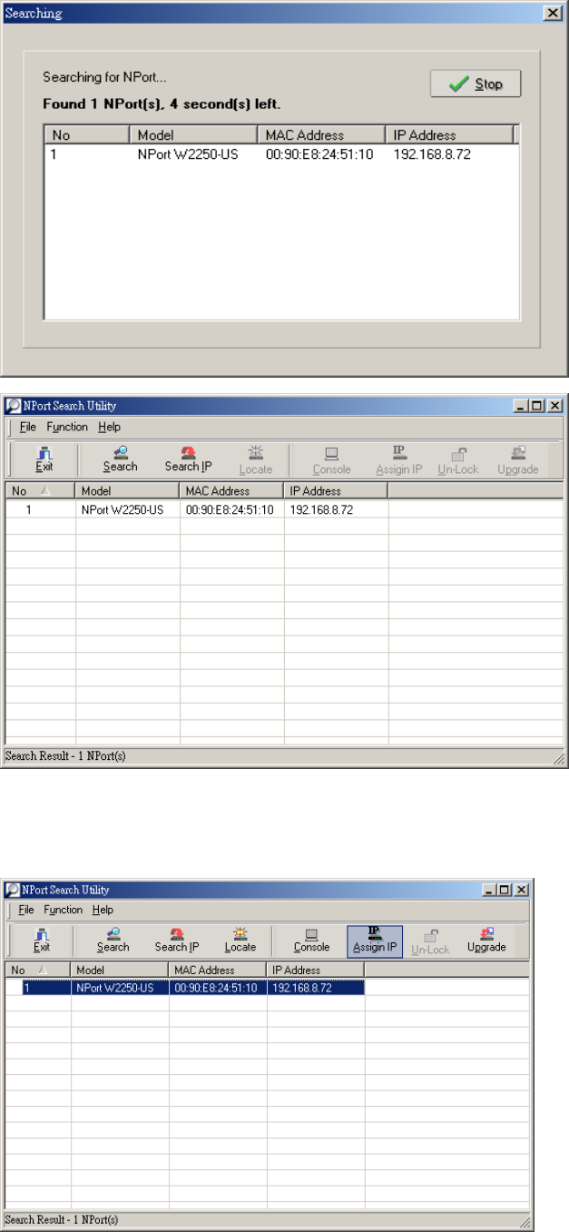
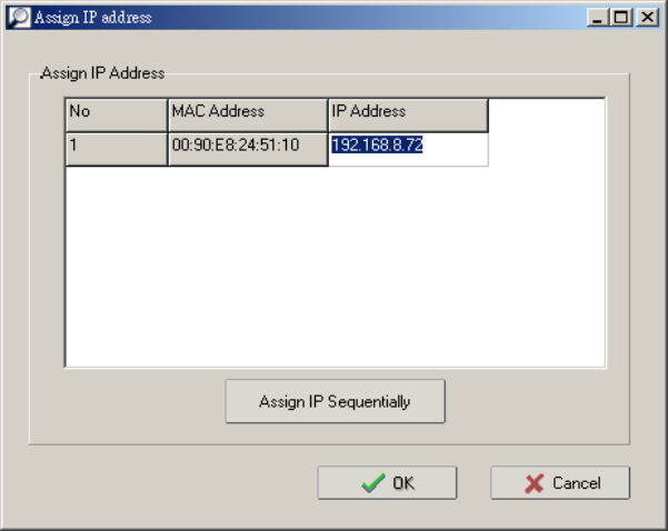
1. Open NPort Search Utility ,click” search”
2. When the search is complete, the Broadcast Search window
closes, and the NPort W2250/W2150s that were located are
displayed in the window.
3. You can click “assign IP” to change the IP if you need.
Installation for Real TTY and Fixed TTY
<Install real TTY driver >
1. Procedure
To map NPort serial port to host tty port, you need to:
(1). Setup NPort.
Make sure the IP configuration is ok and you can access
the NPort (ping, telnet...) seccussfully. Then you MUST
configure the NPort serial port to "Real COM Mode".
(2). Install driver files into the host.
Refer to "3.Driver Files Installation"
(3). Map NPort serial to host tty port.
Refer to "4.Mapping TTY Ports"
2. Hardware Installation
Prior to proceed to software installation, please make sure the
hardware installation is completed as user's manual illustrated.
The default IP address for NPort Server is 192.168.127.254.
!!!!!!!!!!!!!!!!!!!!!!! NOTE !!!!!!!!!!!!!!!!!!!!!!!!!!!!
After hardware installation, you MUST configure the NPort
operating mode to "Real COM Mode".
!!!!!!!!!!!!!!!!!!!!!!! NOTE !!!!!!!!!!!!!!!!!!!!!!!!!!!!
3. Driver Files Installation
a. Get the driver file from product CD-ROM or web site.
b. Login into the console as a super user (root).
c. Execute 'cd /' to go to root directory.
d. Copy the driver file npreal2xx.tgz into '/' directory.
e. Execute 'tar xvfz npreal2xx.tgz' to copy all files into the system.
f. Execute '/tmp/moxa/mxinst'.
!!!!!!!!!!!!!!!!!!!!!!! NOTE !!!!!!!!!!!!!!!!!!!!!!!!!!
For RedHat AS/ES/WS and Fedora Core1, extra
argument is needed:
# /tmp/moxa/mxinst SP1
!!!!!!!!!!!!!!!!!!!!!!! NOTE !!!!!!!!!!!!!!!!!!!!!!!!!!
g. The shell script will install the driver files automatically.
After installing driver successfully, you can see the
several files in /usr/lib/npreal2/driver, inlcuding
- mxaddsvr (Add Server, mapping tty port)
- mxdelsvr (Delete Server, un-mapping tty port)
- mxloadsvr (Reload Server)
- mxmknod (Create device node/tty port)
- mxrmnod (Remove device node/tty port)
- mxuninst (Remove tty port and driver files)
Now you are ready to map NPort serial port into system tty port.
Please see "4.Mapping TTY Ports".
4. Mapping TTY Ports
Before mapping tty ports, you have to set the operation mode of
your NPort Product to "Real Com Mode". We provide two ways to map
tty ports.
Mapping tty ports automatically
After logging in as a super user, you can enter the directory
"/usr/lib/npreal2/driver" and then execute "mxaddsvr" program
to map the target NPort serial port to host tty ports.
The syntax of mxaddsvr is:
"mxaddsvr [NPort IP Address] [Total Ports] ([Data port] [Cmd port])"
For example1:
# cd /usr/lib/npreal2/driver
# ./mxaddsvr 192.168.3.4 16
For example2:
# cd /usr/lib/npreal2/driver
# ./mxaddsvr 192.168.3.4 16 4001 966
In example1, 16 tty ports will be added with ip "192.168.3.4" and
data port(950, 951, ...965), command port(966, 967, 968.., 981).
In example2, 16 tty ports will be added with ip "192.168.3.4" and
data port(4001, 4002, ..4016), command port(966, 967, 968.., 981).
The following actions will be performed.
- Modify the "npreal2d.cf"
- Create tty ports in directory "/dev" with major & minor number
configured in "npreal2d.cf".
- Stop and then restart the driver.
5. Remove Mapped TTY ports
Similar to "Mapping TTY Ports", we provide two ways:
Remove the mapped tty ports automatically
After logging in as root, you can enter the directory
"/usr/lib/npreal2/driver" and then execute "mxdelsvr"
program to delete a server. The syntax of mxdelsvr is
"mxdelsvr [IP]", For example:
# cd /usr/lib/npreal2/driver
# ./mxdelsvr 192.168.3.4
If you don't provide the IP address in the command line, the
program will list the installed servers and total ports on screen.
So you can only choose the index on the installed server list to delete.
The following actions will be performed.
- Modify the "npreal2d.cf"
- Remove the relevant tty ports in directory "/dev"
- Stop and then restart the driver.
6. Driver Files Removal
Drvier Removal will remove all driver files, mapped tty ports and
unload the driver. To do this, you only need to enter the directory
"/usr/lib/npreal2/driver", and then execute "mxuninst" to uninstall
the driver. This program will perform the following actions.
- Unload the driver.
- Delete all files and directories in "/usr/lib/npreal2"
- Delete directory "/usr/lib/npreal2".
- Modify the system initializing script file.
<Install fixed TTY driver >
1. Installation and Configuration
step 1 : login to UNIX and create a directory for MOXA TTY,
for instance, /usr/etc.
# mkdir /usr/etc
# cd /usr/etc
step 2 : Extract source code from tar-file :
Type "tar xvf moxattyd.tar".
After extract, you can find the following files :
README --> this file
moxattyd.c --> source program
moxattyd.cf --> empty configuration file
Makefile --> makefile
step 3 : Compile and Link :
For SCO UNIX:
# make sco
For Linux:
# make linux
For UnixWare 7:
# make svr5
For UnixWare 2.1.x, SVR4.2:
# make svr42
For IBM AIX:
# make aix
For HP-UNIX:
# make hpunix
For SunOS 5.8:
# make sun
For QNX6:
# make qnx6
step 4 : Modify configuration :
The configuration of moxattyd program is defined on
"moxattyd.cf" file at the same directory where contains
program moxattyd.
User can use vi or any edit to modify it. It's a text
file.
For more configuration information, please take a look
at moxattyd.cf file. We put detail decription on it.
!!!!!!!!!!!!!!!!!!!!!!!!!!!!!!!!!!!!!!!!!!!!!!!!!!!!
Please note that the "Device Name" is depended on OS.
See "E. Device Naming Rule" for more information.
!!!!!!!!!!!!!!!!!!!!!!!!!!!!!!!!!!!!!!!!!!!!!!!!!!!!
step 5 : Add program moxattyd into /etc/inittab and any tty name
you configued at moxattyd.cf.
eg. for Linux:
ts:2:respawn:/usr/etc/moxattyd
p1:345:respawn:/etc/mingetty ttyp1
p2:345:respawn:/etc/mingetty ttyp2
finish : You have finished the installation and configuration
of MOXA TTY.
2. Start moxattyd program
Run "init q" or reboot your UNIX.
3. Add additional server
Step 1: Modify "moxattyd.cf" file to add additional server.
User can use vi or any edit to modify it. It's a text
file.
For more configuration information, please take a look
at moxattyd.cf file. We put detail decription on it.
Step 2: Find the proccess id (PID) of program "moxattyd".
# ps -ef | grep moxattyd
Step 3: Update configuration of moxattyd program.
# kill -USR1 PID
(ex. if "moxattyd" PID = 404, "kill -USR1 404")
finish : You have finished to add additional server.
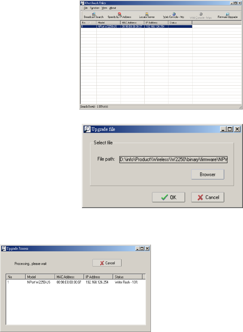
Upgrade Firmware
1. Open NPort Search
Utility ,Right click on a
specific NPort
W2250/W2150 and
select the Upgrade
Firmware function to
start upgrading the
firmware.
2. Select the correct
ROM file to be
downloaded to the NPort
W2250/W2150.
3. Wait patiently while the Upgrade Firmware action is being
processed.
4.click”close” to finish firmware upgrade.
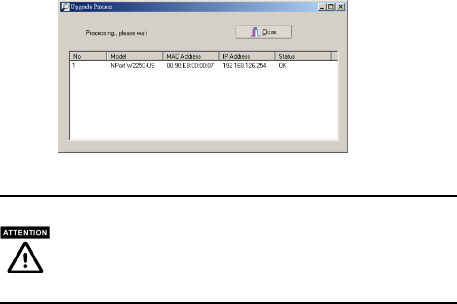
You can simultaneously upgrade the firmware of multiple NPort W2250/W2150s
that are of the same model.
To select multiple NPort W2250/W2150s, hold down the Ctrl key when selecting
an additional NPort W2250/W2150, or hold down the Shift key to select a block
of NPort W2250/W2150s.

A
A
SNMP Agents with MIB II & RS-232
like groups
-----------------------------------------------------------------------------------------------------
NPort has built-in SNMP (Simple Network Management Protocol) agent software that
supports SNMP Trap, RFC1317 RS-232 like groups and RFC 1213 MIB-II. The
following table lists the standard MIB-II groups, as well as the variable
implementation for NPort .
RFC1213 MIB-II supported SNMP variables:
System Interfaces IP MIB ICMP MIB
SysDescr itNumber ipForwarding IcmpInMsgs
SysObjectID ifIndex ipDefaultTTL IcmpInErrors
SysUpTime ifDescr ipInreceives IcmpInDestUnreachs
SysContact ifType ipInHdrErrors IcmpInTimeExcds
SysName ifMtu ipInAddrErrors IcmpInParmProbs
SysLocation ifSpeed ipForwDatagrams IcmpInSrcQuenchs
SysServices ifPhysAddress ipInUnknownProtos IcmpInRedirects
ifAdminStatus ipInDiscards IcmpInEchos
ifOperStatus ipInDelivers IcmpInEchoReps
ifLastChange ipOutRequests IcmpInTimestamps
ifInOctets ipOutDiscards IcmpTimestampReps
ifInUcastPkts ipOutNoRoutes IcmpInAddrMasks
ifInNUcastPkts ipReasmTimeout IcmpOutMsgs
ifInDiscards ipReasmReqds IcmpOutErrors
ifInErrors ipReasmOKs IcmpOutDestUnreachs

System Interfaces MIB IP MIB ICMP MIB
SysServices ifInUnknownProtos ipReasmFails IcmpOutTimeExcds
ifOutOctets ipFragOKs IcmpOutParmProbs
ifOutUcastPkts ipFragFails IcmpOutSrcQuenchs
ifOutNUcastPkts ipFragCreates IcmpOutRedirects
ifOutDiscards ipAdEntAddr IcmpOutEchos
ifOutErrors ipAdEntIfIndex IcmpOutEchoReps
ifOutQLen ipAdEntNetMask IcmpOutTimestamps
ifSpecific ipAdEntBcastAddr IcmpOutTimestampReps
ipAdEntReasmMaxSize IcmpOutAddrMasks
IpNetToMediaIfIndex IcmpOutAddrMaskReps
IpNetToMediaPhysAddress
IpNetToMediaNetAddress
IpNetToMediaType
IpRoutingDiscards
UDP MIB TCP MIB SNMP MIB
UdpInDatagrams tcpRtoAlgorithm snmpInPkts
UdpNoPorts tcpRtoMin snmpOutPkts
UdpInErrors tcpRtoMax snmpInBadVersions
UdpOutDatagrams tcpMaxConn snmpInBadCommunityNames
UdpLocalAddress tcpActiveOpens snmpInASNParseErrs
UdpLocalPort tcpPassiveOpens snmpInTooBigs
tcpAttempFails snmpInNoSuchNames
Address tcpEstabResets snmpInBadValues
AtIfIndex tcpCurrEstab snmpInReadOnlys
AtPhysAddress tcpInSegs snmpInGenErrs
AtNetAddress tcpOutSegs snmpInTotalReqVars

Address Translation TCP MIB SNMP MIB
AtNetAddress tcpRetransSegs snmpInTotalSetVars
tcpConnState snmpInGetRequests
tcpConnLocalAddress snmpInGetNexts
tcpConnLocalPort snmpInSetRequests
tcpConnRemAddress snmpInGetResponses
tcpConnRemPort snmpInTraps
tcpInErrs snmpOutTooBigs
tcpOutRsts snmpOutNoSuchNames
snmpOutBadValues
snmpOutGenErrs
snmpOutGetRequests
snmpOutGetNexts
snmpOutSetRequests
snmpOutGetResponses
snmpOutTraps
snmpEnableAuthenTraps
RFC1317: RS-232 MIB objects
Generic RS-232-like
Group
RS-232-like General Port
Table
RS-232-like Asynchronous
Port Group
rs232Number rs232PortTable rs232AsyncPortTable
rs232PortEntry rs232AsyncPortEntry
rs232PortIndex rs232AsyncPortIndex
rs232PortType rs232AsyncPortBits
rs232PortInSigNumber rs232AsyncPortStopBits
rs232PortOutSigNumber rs232AsyncPortParity
rs232PortInSpeed
rs232PortOutSpeed
The Input Signal Table The Output Signal Table
rs232InSigTable rs232OutSigTable
rs232InSigEntry rs232OutSigEntry
rs232InSigPortIndex rs232OutSigPortIndex
rs232InSigName rs232OutSigName
rs232InSigState rs232OutSigState

B
B
Well Known Port Numbers
---------------------------------------------------------------------------------------------------
In this appendix, which is included for your reference, we provide a list of Well
Known port numbers that may cause network problems if you set NPort 5200 to one
of these ports. Refer to RFC 1700 for Well Known port numbers, or refer to the
following introduction from the IANA.
The port numbers are divided into three ranges: the Well Known Ports, the Registered
Ports, and the Dynamic and/or Private Ports.
The Well Known Ports range from 0 through 1023.
The Registered Ports range from 1024 through 49151.
The Dynamic and/or Private Ports range from 49152 through 65535.
The Well Known Ports are assigned by the IANA, and on most systems, can only be
used by system processes or by programs executed by privileged users. The following
table shows famous port numbers among the well-known port numbers. For more
details, please visit the IANA website at
http://www.iana.org/assignments/port-numbers.
TCP Socket Application Service
0 reserved
1 TCP Port Service Multiplexor
2 Management Utility
7 Echo
9 Discard
11 Active Users (systat)
13 Daytime
15 Netstat
20 FTP data port
21 FTP CONTROL port
23 Telnet
25 SMTP (Simple Mail Transfer
37 Time (Time Server)
42 Host name server (names server)
43 Whois (nickname)

49 (Login Host Protocol) (Login)
53 Domain Name Server (domain)
79 Finger protocol (Finger)
TCP Socket Application Service
80 World Wibe Web HTTP
119 Netword news Transfer Protocol
123 Network Time Protocol
213 IPX
160 – 223 Reserved for future use
UDP Socket Application Service
0 reserved
2 Management Utility
7 Echo
9 Discard
11 Active Users (systat)
13 Daytime
35 Any private printer server
39 Resource Location Protocol
42 Host name server (names server)
43 Whois (nickname)
49 (Login Host Protocol) (Login)
53 Domain Name Server (domain)
69 Trivial Transfer Protocol (TETP)
70 Gopler Protocol
79 Finger Protocol
80 World Wide Web HTTP
107 Remote Telnet Service
111 Sun Remote Procedure Call (Sunrpc)
119 Network news Tcanster Protocol
123 Network Time protocol (nnp)
161 SNMP (Simple Network Mail
162 SNMP Traps
213 IPX (Used for IP Tunneling)
C
C
Service Information
----------------------------------------------------------------------------------------------------
This appendix shows you how to contact Moxa for information about this and other
products, and how to report problems.
MOXA Internet Services
Customer satisfaction is our number one concern, and to ensure that customers receive
the full benefit of our products, Moxa Internet Services has been set up to provide
technical support, driver updates, product information, and user’s manual updates.
The following services are provided
E-mail for technical support ...............support@moxa.com.tw
World Wide Web (WWW) Site for product information:
........................http://www.moxa.com or
........................http://www.moxa.com.tw

D
D
A. Federal Communication Commission
Interference Statement
This equipment has been tested and found to comply with the
limits for a Class B digital device, pursuant to Part 15 of the FCC
Rules. These limits are designed to provide reasonable protection
against harmful interference in a residential installation. This
equipment generates, uses and can radiate radio frequency
energy and, if not installed and used in accordance with the
instructions, may cause harmful interference to radio
communications. However, there is no guarantee that
interference will not occur in a particular installation. If this
equipment does cause harmful interference to radio or television
reception, which can be determined by turning the equipment off
and on, the user is encouraged to try to correct the interference
by one or more of the following measures:
-- Reorient or relocate the receiving antenna.
-- Increase the separation between the equipment and receiver.
-- Connect the equipment into an outlet on a circuit different from
that to which the receiver is connected.
-- Consult the dealer or an experienced radio/TV technician for
help.
CAUTION:
Any changes or modifications not expressly approved by the
grantee of this device could void the user's authority to operate
the equipment.
FCC RF Radiation Exposure Statement
This equipment complies with FCC RF radiation exposure limits set forth for an
uncontrolled environment. This equipment should be installed and operated with a
minimum distance of 20cm between the radiator and your body.
This device complies with Part 15 of the FCC Rules. Operation
is subject to the following two conditions:
(1) This device may not cause harmful interference and
(2) This device must accept any interference received, including
interference that may cause undesired operation.