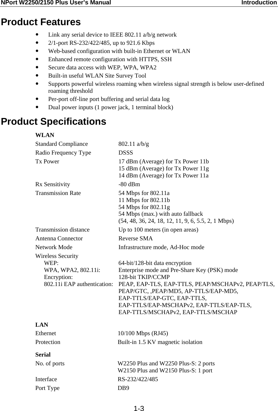
Moxa W2250PLUS NPort W2250/2150 Plus User Manual NPort W2250 2150 Plus User s Manual
Moxa Inc. NPort W2250/2150 Plus NPort W2250 2150 Plus User s Manual
UserManual.wiki
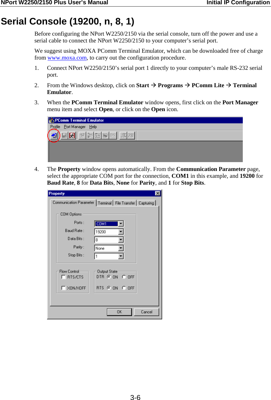
>
Moxa
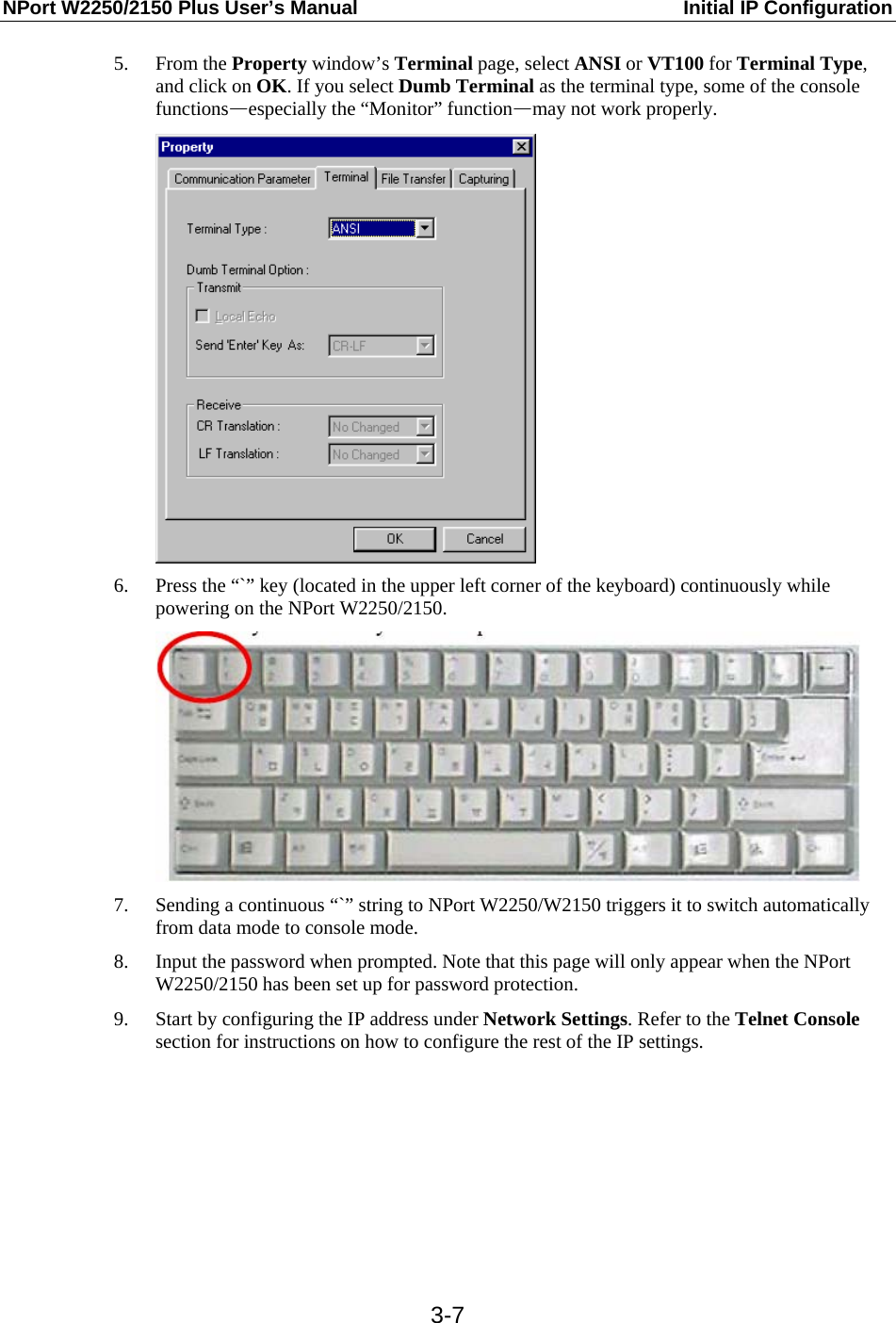
>
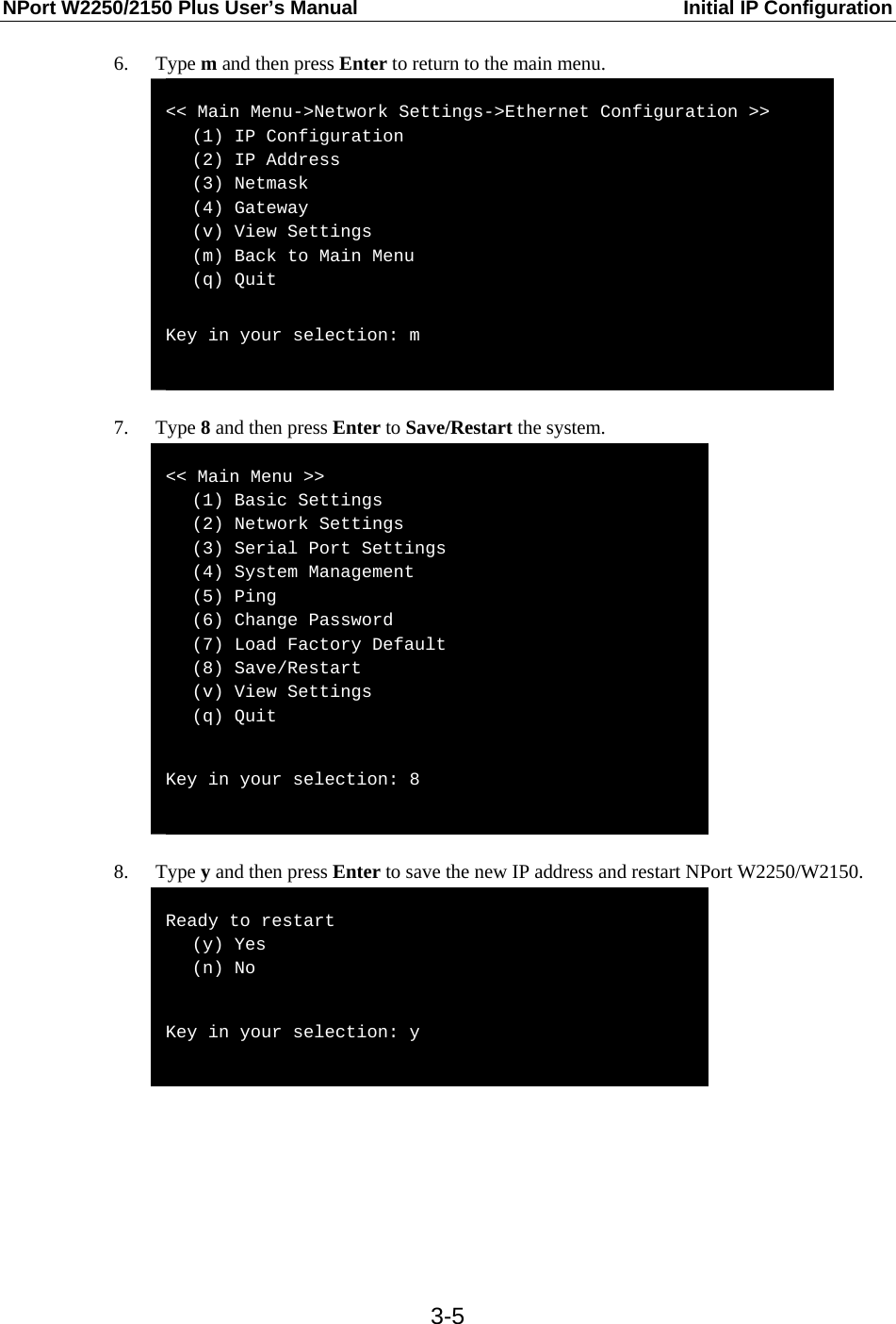
W2250PLUS User Manual
Manual
Navigation menu
Upload a User Manual
Namespaces
Wiki Guide
HTML
PDF
Info
Views
User Manual
Discussion / Help
Navigation


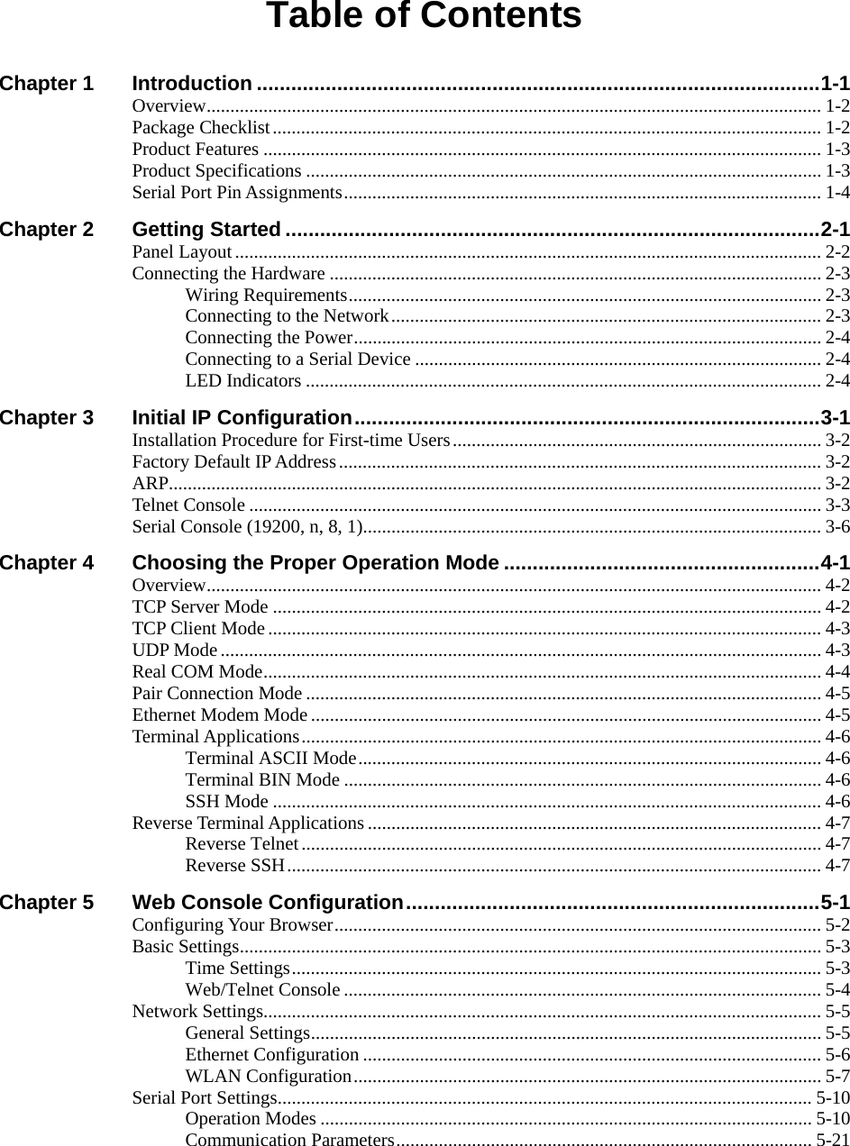
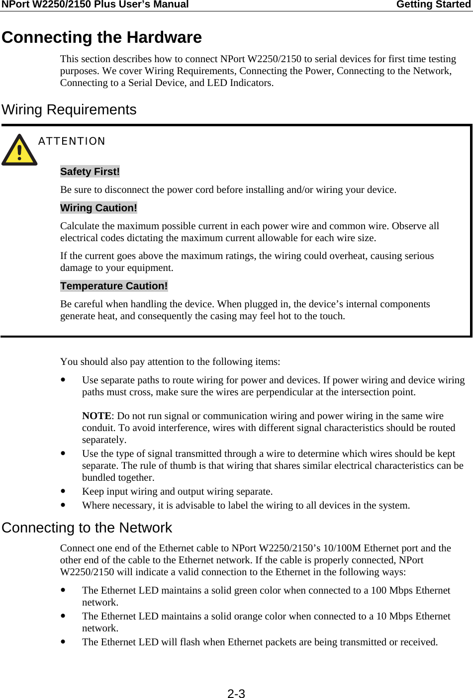
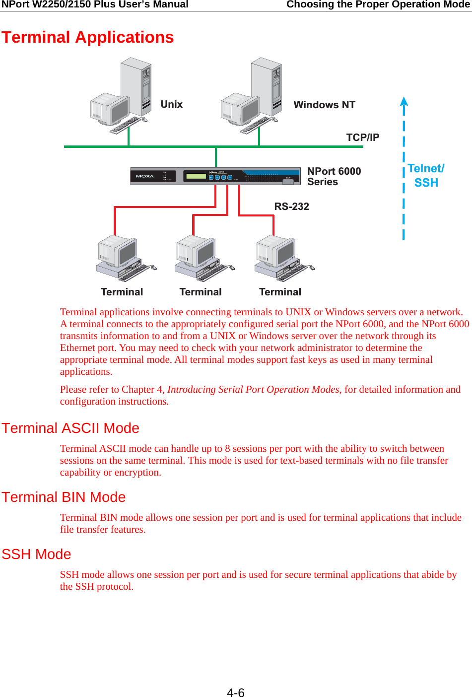
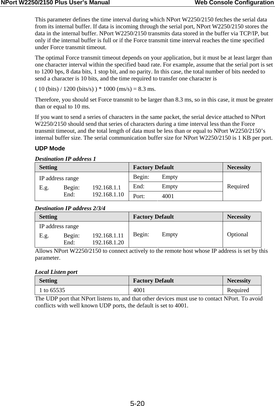
![NPort W2250/2150 Plus User’s Manual Getting Started 2-4Connecting the Power Connect the 12-48 VDC power line with NPort W2250/2150’s power jack. When the power is properly supplied, the “Ready” LED will show a solid red color until the system is ready, at which time the “Ready” LED will change to a green color. Connecting to a Serial Device Connect the serial data cable between NPort W2250/2150 and the serial device. Serial data cables are optional accessories for NPort W2250/2150. Refer to Chapter 1 under Optional Accessories in the Ordering Information section for information about the RJ45-to-DB25 and RJ45-to-DB9 cables. LED Indicators Top Panel LED Indicators Name Color Function red Steady on: Power is on and NPort is booting up. Blinking: Indicates a LAN IP conflict, or that the DHCP or BOOTP server did not respond properly. green Steady on: Power is on and NPort is functioning normally. Blinking: The device server has been located by the NPort Search Utility. Ready off Power is off, or a power error condition exists. WLAN green Steady on: Wireless enabled. Blinking: Indicates a WLAN IP conflict, or that the DHCP or BOOTP server did not respond properly. orange Serial port is receiving data. green Serial port is transmitting data. Serial 1 Serial 2 off No data is being transmitted or received through the serial port. Signal Strength (5 LEDS) green The number of lit LEDS indicates the WLAN signal strength. When [ 0 / 1 / 2 / 3 / 4 / 5 ] LEDs are lit, the corresponding WLAN status is [ Connection Fail / Bad / Fair / Good / Very Good / Excellent ]. End Panel LED Indicators Name Color Function orange 10 Mbps Ethernet connection. green 100 Mbps Ethernet connection. Ethernet off Ethernet cable is disconnected, or has a short.](https://usermanual.wiki/Moxa/W2250PLUS/User-Guide-802097-Page-12.png)

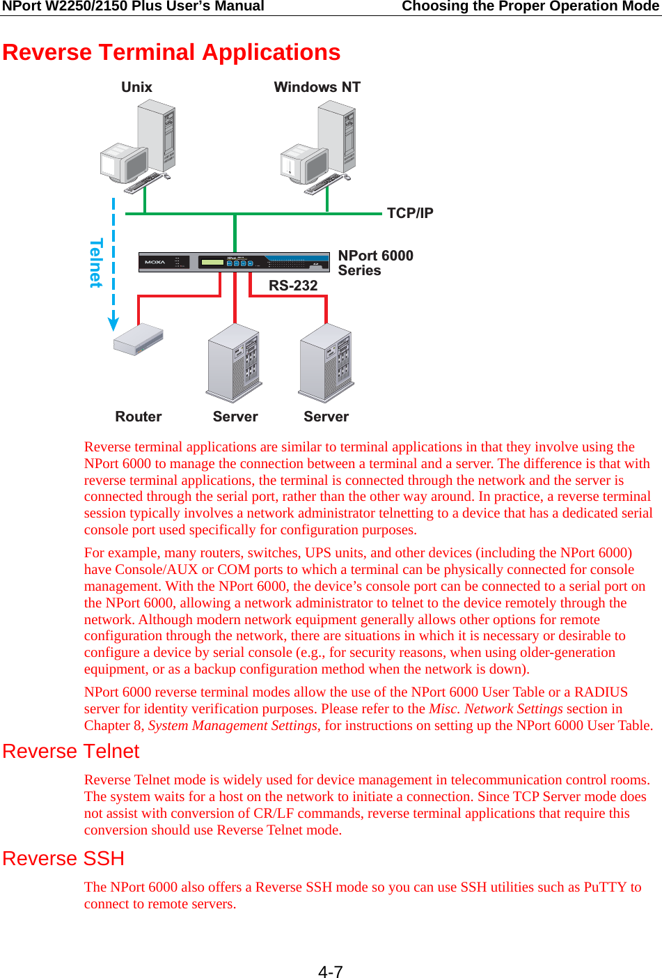
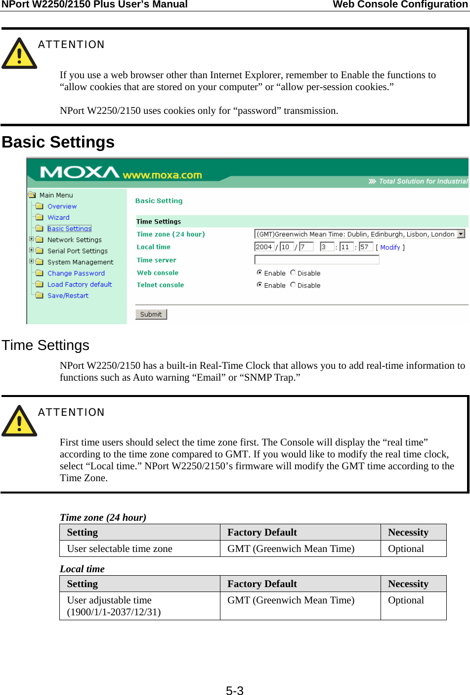
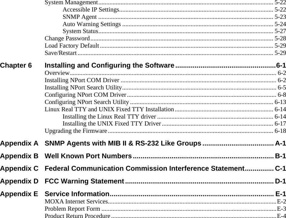
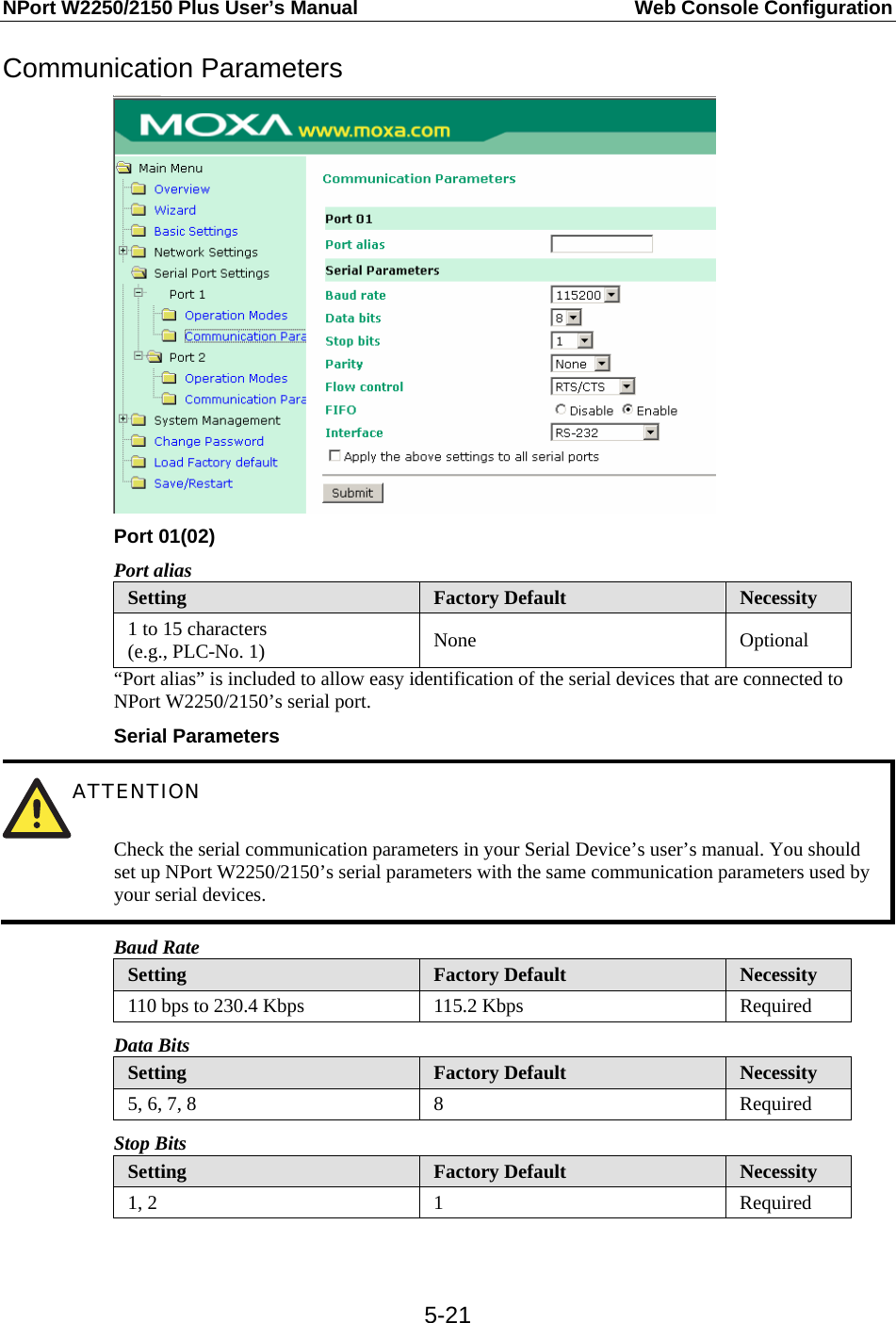
![NPort W2250/2150 Plus User’s Manual Web Console Configuration 5-4Click on the [ Modify ] button to open the Modify time settings window to input the correct local time. Time server Setting Factory Default Necessity IP Address or Domain Name (E.g., 192.168.1.1, time.stdtime.gov.tw, or time.nist.gov) None Optional NPort W2250/2150 uses SNTP (RFC-1769) for auto time calibration. Input the correct “Time server” IP address or domain name. Once NPort W2250/2150 is configured with the correct Time server address, NPort W2250/2150 will request time information from the “Time server” every 10 minutes. Web/Telnet Console The “Disable” option for “Web Console” and “Telnet Console” is included for security reasons. In some cases, you may want to Disable one or both of these console utilities as an extra precaution to prevent unauthorized users from accessing your NPort W2250/2150. The factory default for both Web console and Telnet console is Enable. Web/Telnet Console Setting Factory Default Necessity Enable or Disable Enable Required](https://usermanual.wiki/Moxa/W2250PLUS/User-Guide-802097-Page-32.png)
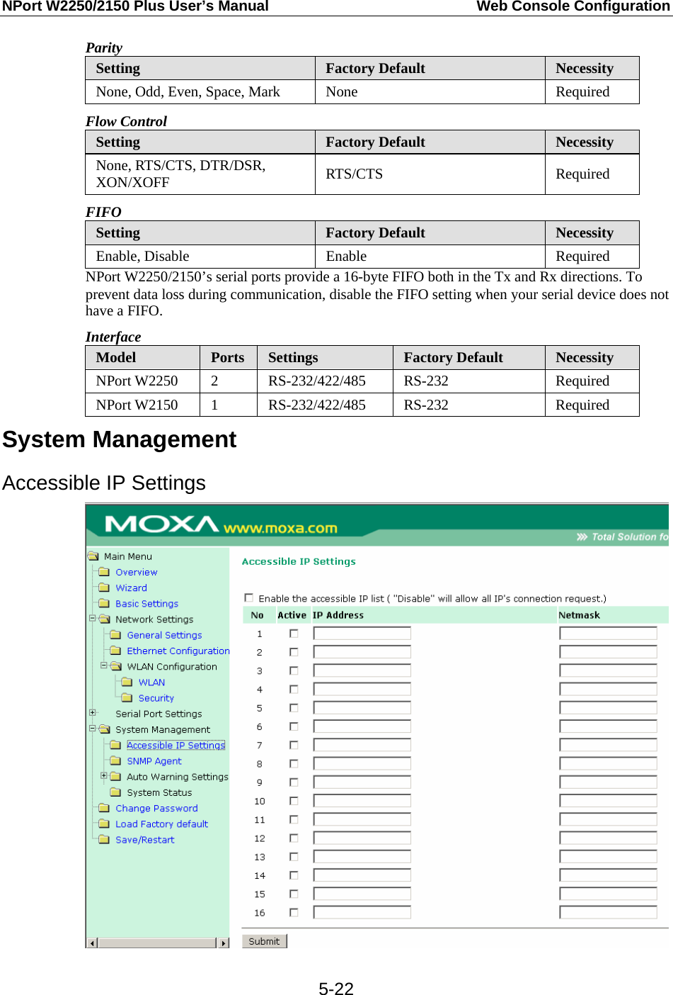
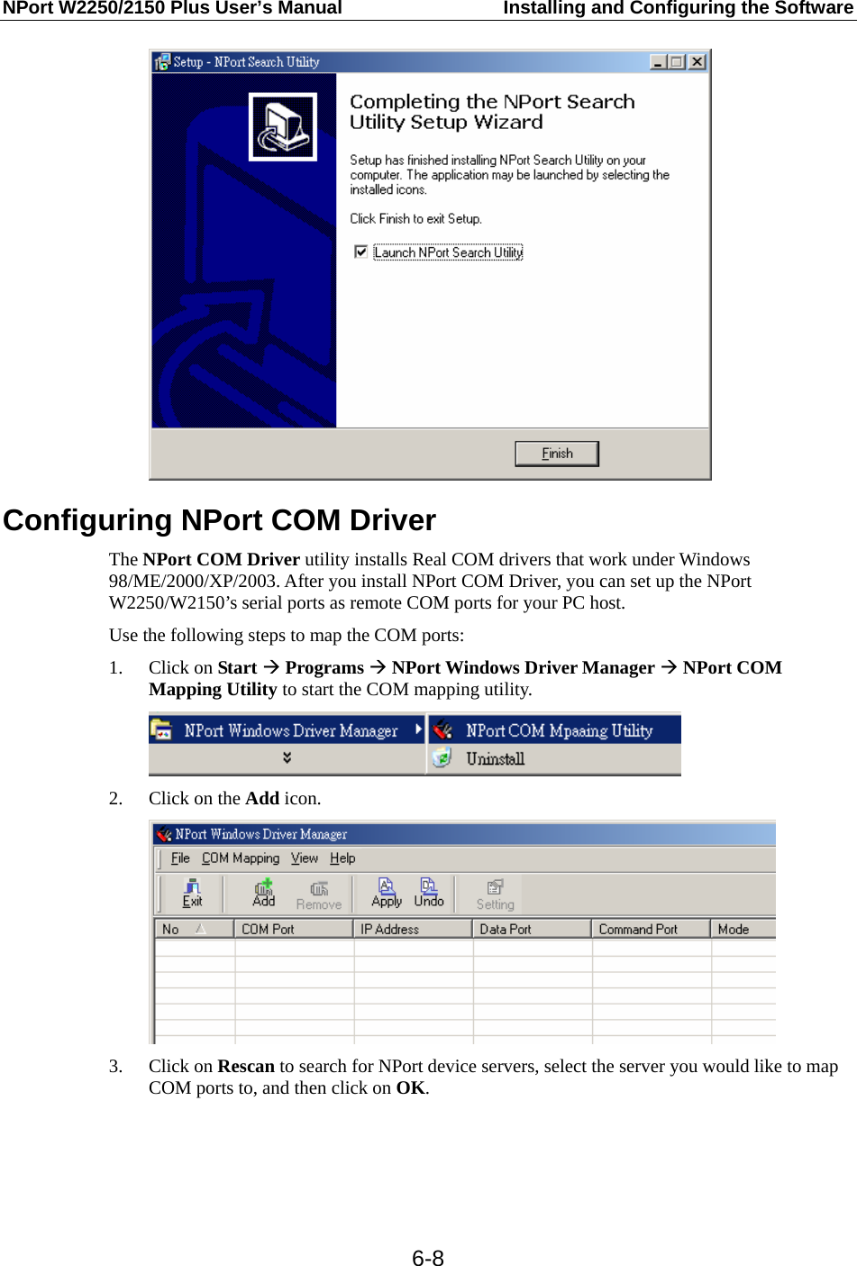
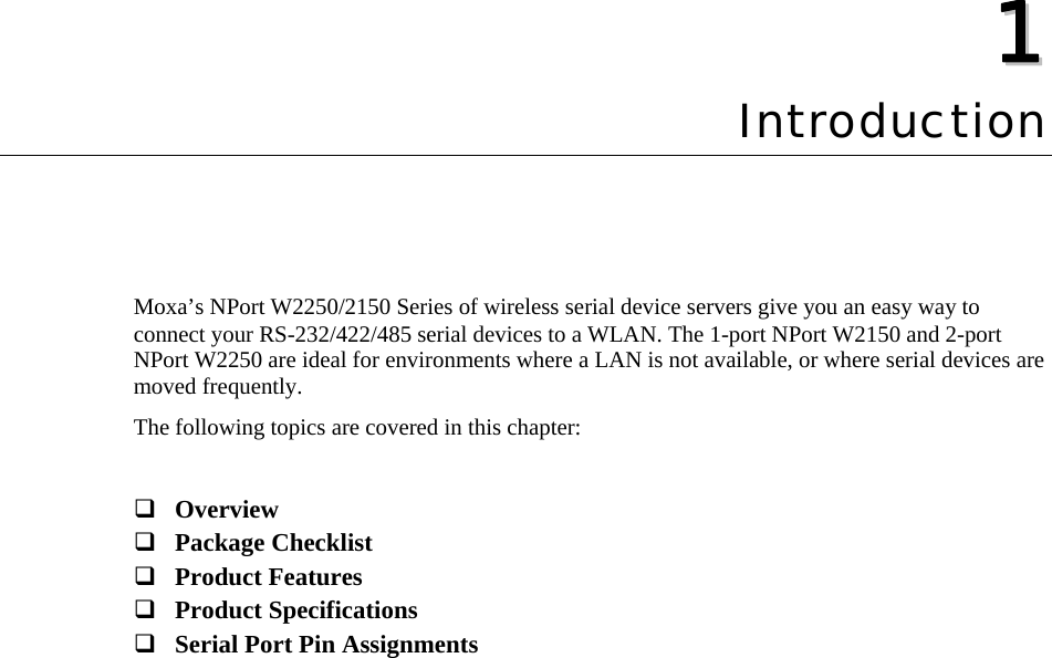
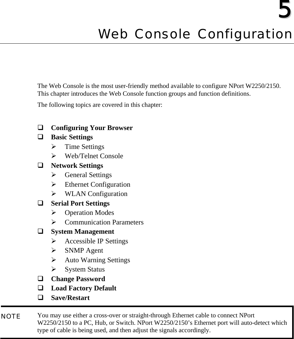
![NPort W2250/2150 Plus User’s Manual Installing and Configuring the Software 6-15Hardware Installation Before proceeding with the software installation, make sure you have completed the hardware installation, as described in an earlier chapter of this manual. The default IP address of the Ethernet interface is 192.168.126.254 and the default IP address of the WLAN interface is 192.168.127.254.. NOTE After installing the hardware, you MUST configure the NPort operating mode to Real COM Mode. Installing the Driver File a. Copy the driver file from the product’s CD-ROM or Moxa website. b. Log in to the console as a super user (root). c. Execute cd / to change to the root directory. d. Copy the driver file npreal2xx.tgz to the “ / ” directory. e. Execute tar xvfz npreal2xx.tgz to copy all files into the system. f. Execute /tmp/moxa/mxinst. NOTE For RedHat AS/ES/WS and Fedora Core1, extra argument is needed: # /tmp/moxa/mxinst SP1 g. The shell script will install the driver files automatically. After installing the driver, you will be able to see several files in the /usr/lib/npreal2/driver folder, including: > mxaddsvr (Add Server, map tty port) > mxdelsvr (Delete Server, un-map tty port) > mxloadsvr (Reload Server) > mxmknod (Create device node/tty port) > mxrmnod (Remove device node/tty port) > mxuninst (Remove tty port and driver files) At this point, you will be ready to map the NPort serial port to the system tty port. See “Mapping TTY Ports” below for detailed instructions. Mapping TTY Ports Before mapping tty ports, you must set the operation mode of your NPort to Real Com Mode. We provide two ways to map tty ports. a. Mapping tty ports automatically After logging in as a super user, enter the directory /usr/lib/npreal2/driver and then execute mxaddsvr to map the target NPort serial port to the host tty ports. The syntax of mxaddsvr is: mxaddsvr [NPort IP Address] [Total Ports] ([Data port] [Cmd port]) Example 1: # cd /usr/lib/npreal2/driver # ./mxaddsvr 192.168.3.4 16](https://usermanual.wiki/Moxa/W2250PLUS/User-Guide-802097-Page-73.png)
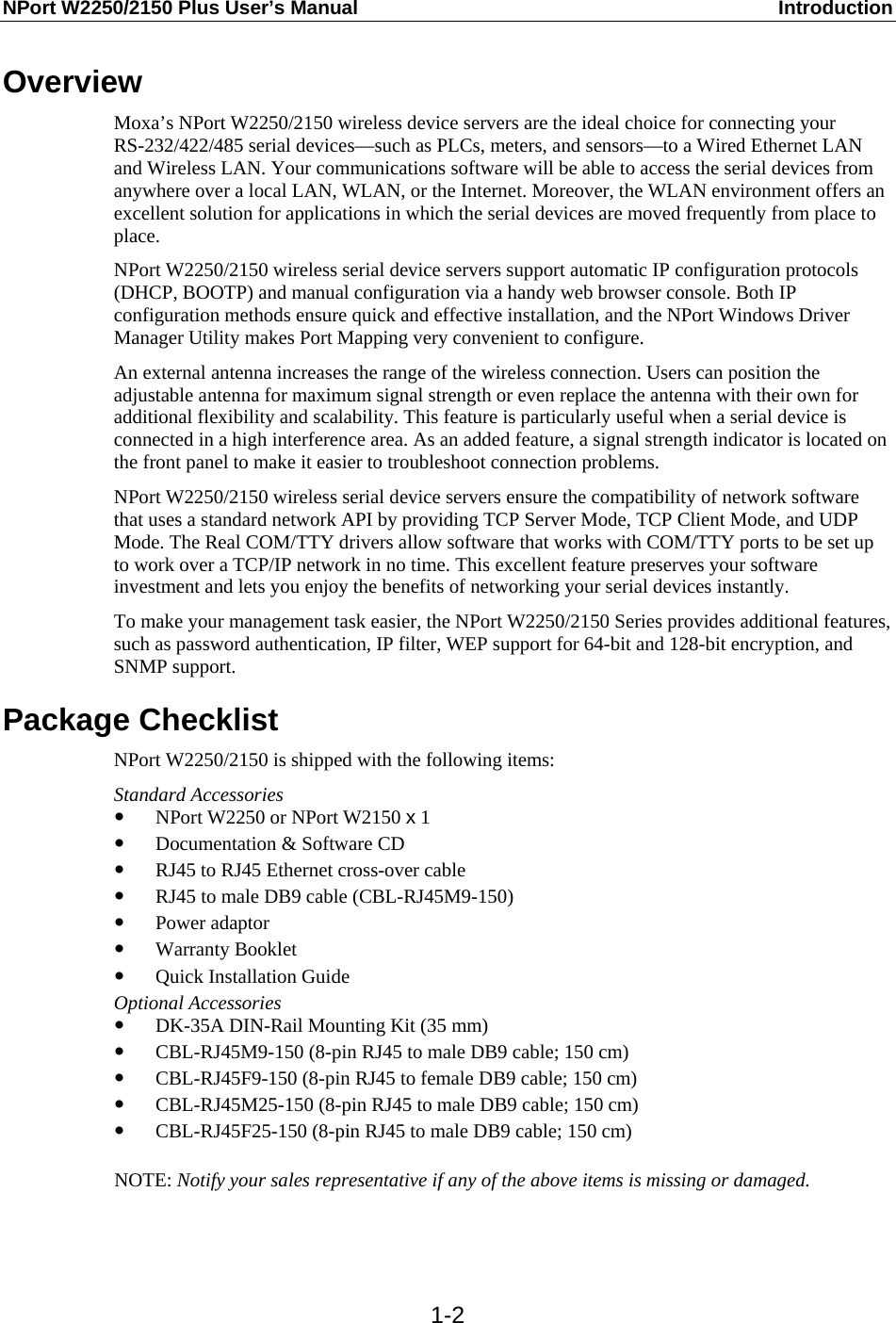
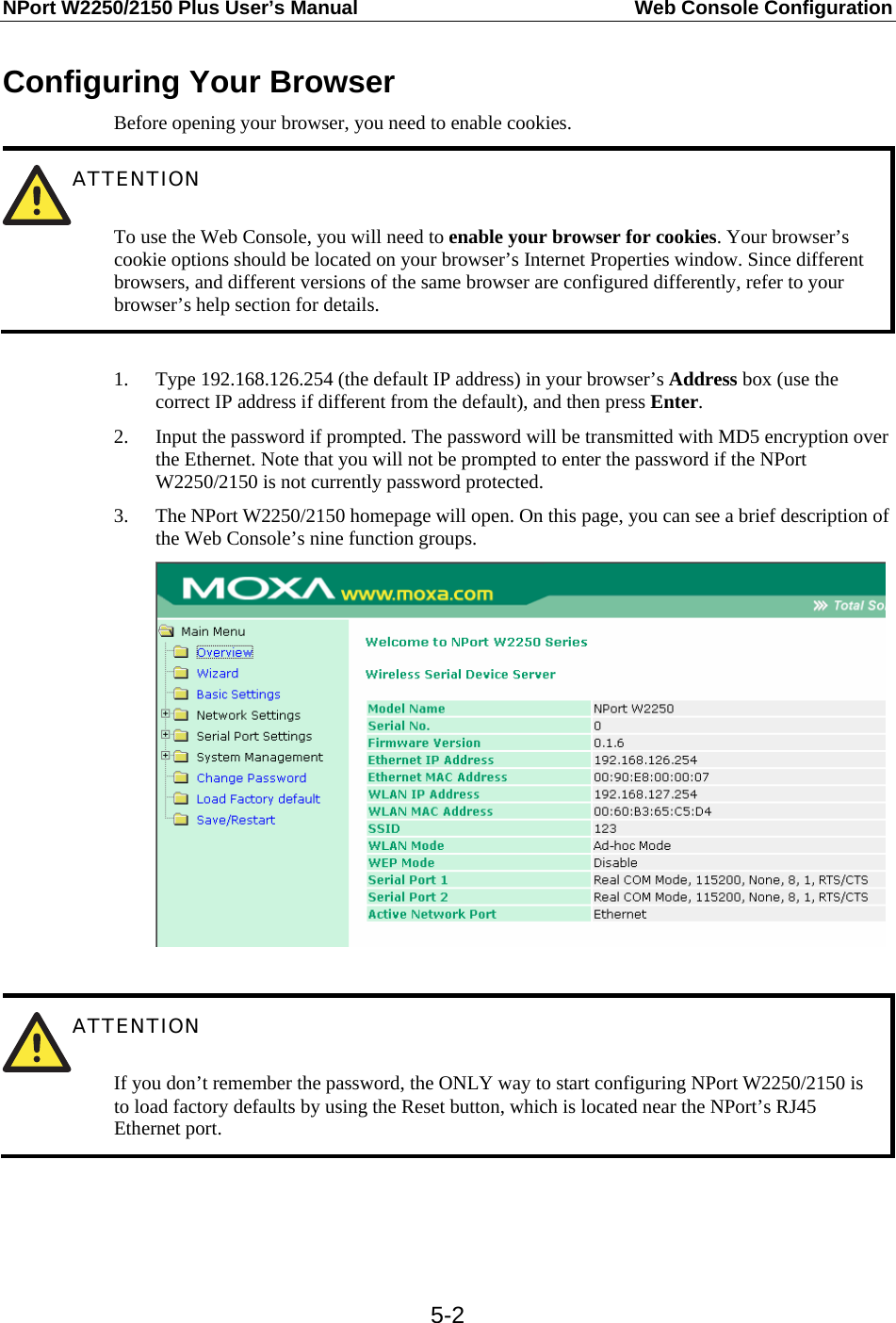
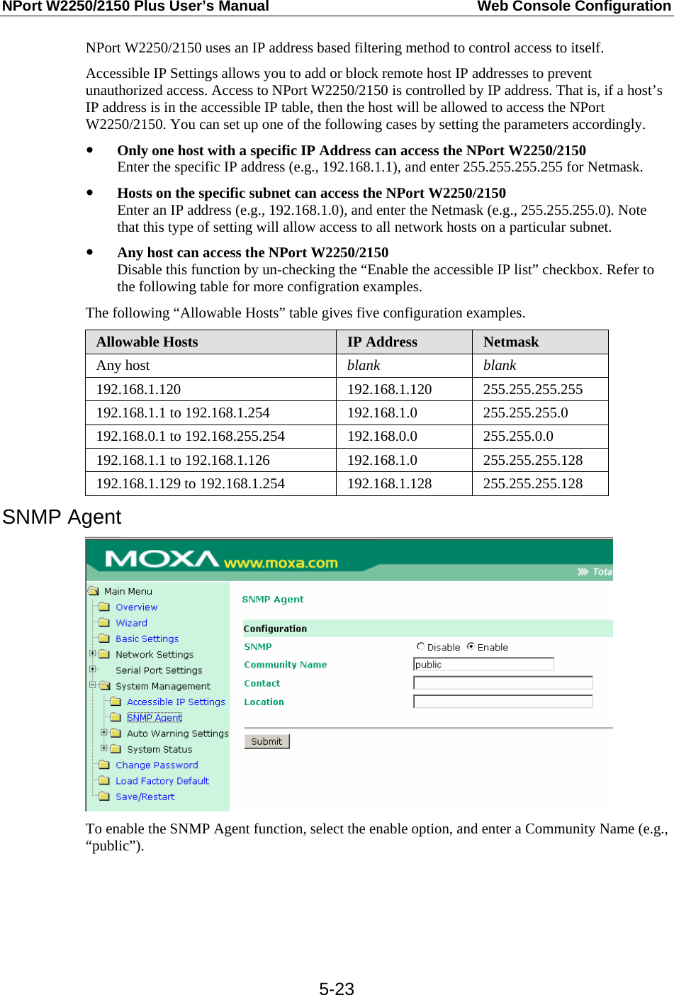
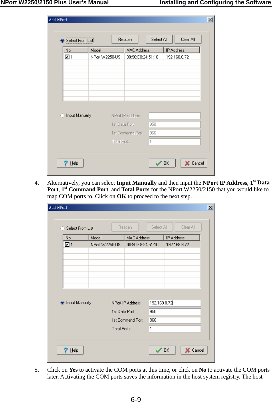
![NPort W2250/2150 Plus User’s Manual Installing and Configuring the Software 6-16Example2: # cd /usr/lib/npreal2/driver # ./mxaddsvr 192.168.3.4 16 4001 966 In Example 1, 16 tty ports will be added, all with IP 192.168.3.4, but with data ports equal to (950, 951, …, 965), and command ports equal to (966, 967, 968, …, 981). In Example 2, 16 tty ports will be added, all with IP 192.168.3.4, but with data ports equal to (4001, 4002, …, 4016), and command ports equal to (966, 967, 968, …, 981). b. Mapping tty ports manually After entering the directory /usr/lib/npreal2/driver, you can modify npreal2d.cf to map NPort serial ports to tty ports, and then execute mxloadsvr to activate the modifications. The following tasks will be performed: > Modify npreal2d.cf > Create tty ports in the directory /dev with major & minor number configured in npreal2d.cf. > Stop and then restart the driver. Removing Mapped TTY ports As with the “Mapping TTY Ports” task, we provide two ways to remove mapped tty ports: a. Removing the mapped tty ports automatically After logging in as root, enter the directory /usr/lib/npreal2/driver and then execute mxdelsvr to delete a server. The syntax of mxdelsvr is: mxdelsvr [IP] Example: # cd /usr/lib/npreal2/driver # ./mxdelsvr 192.168.3.4 If you don’t include the IP address in the command line, a numbered list of IP addresses for servers currently installed, along with the total number of ports for each server, will be listed on the screen. To remove the tty ports for a particular server, type the number next to the server’s IP address and then hit Enter. The following tasks will be performed: > Modify the npreal2d.cf > Remove the relevant tty ports in directory /dev > Stop and then restart the driver. b. Removing the mapped tty ports manually After entering the directory /usr/lib/npreal2/driver, you can modify npreal2d.cf to delete servers and ports manually, and then execute mxloadsvr to activate the modifications. TTY Naming Rule The tty name of the real tty driver is configured in npreal2d.cf. The pre-defined tty name is ttyrXX, and the callout name is curXX. The naming convention is illustrated as follows: NPort Server TTY Name Callout Name 1st (4port) ttyr00 – ttyr03 cur00 – cur03 2nd (8port) ttyr04 – ttyr0b cur04 – cur0b 3rd (16port) ttyr0c – ttyr1b cur0c – cur1b 4th (8port) ttyr1c – ttyr23 cur1c – cur23](https://usermanual.wiki/Moxa/W2250PLUS/User-Guide-802097-Page-74.png)
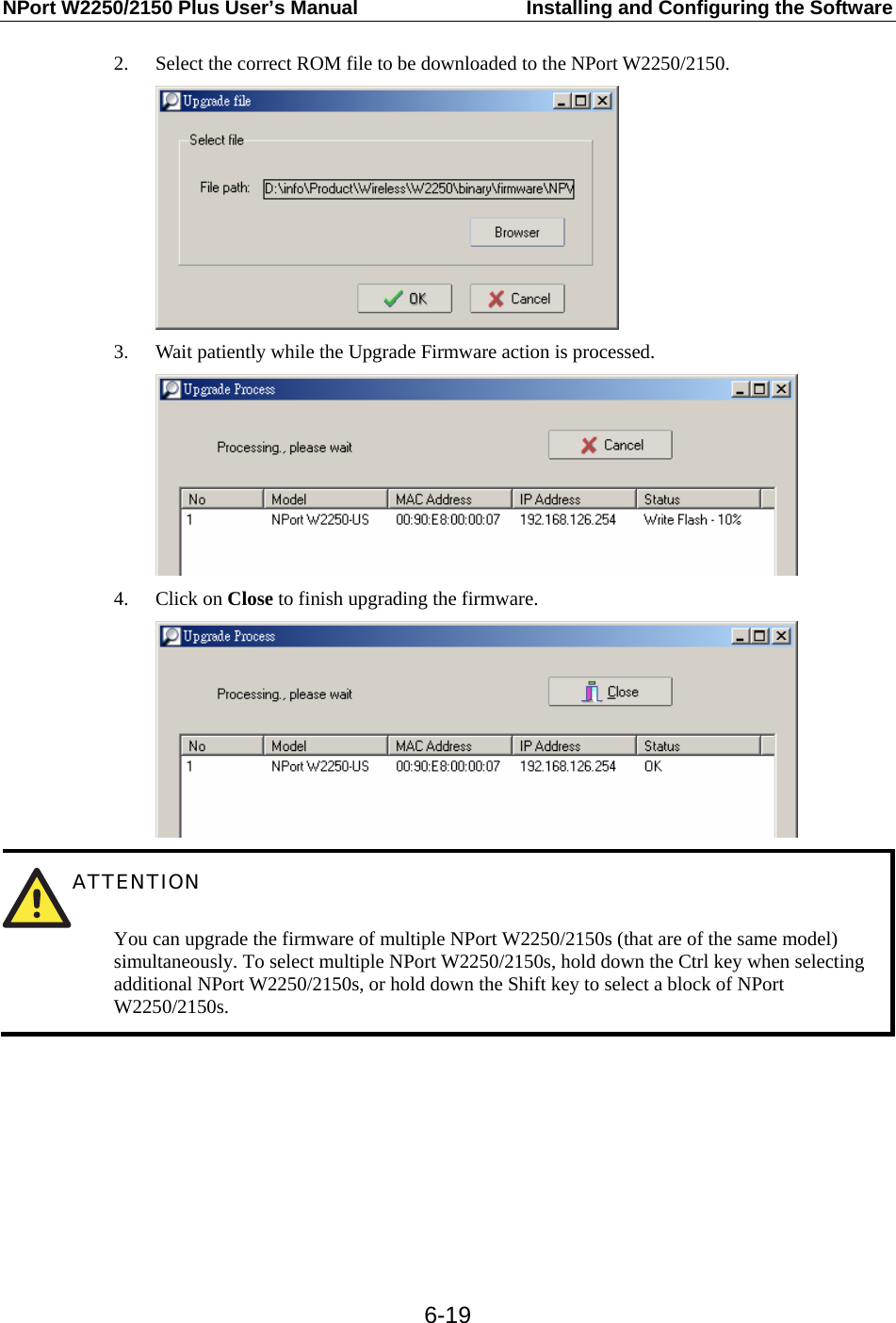
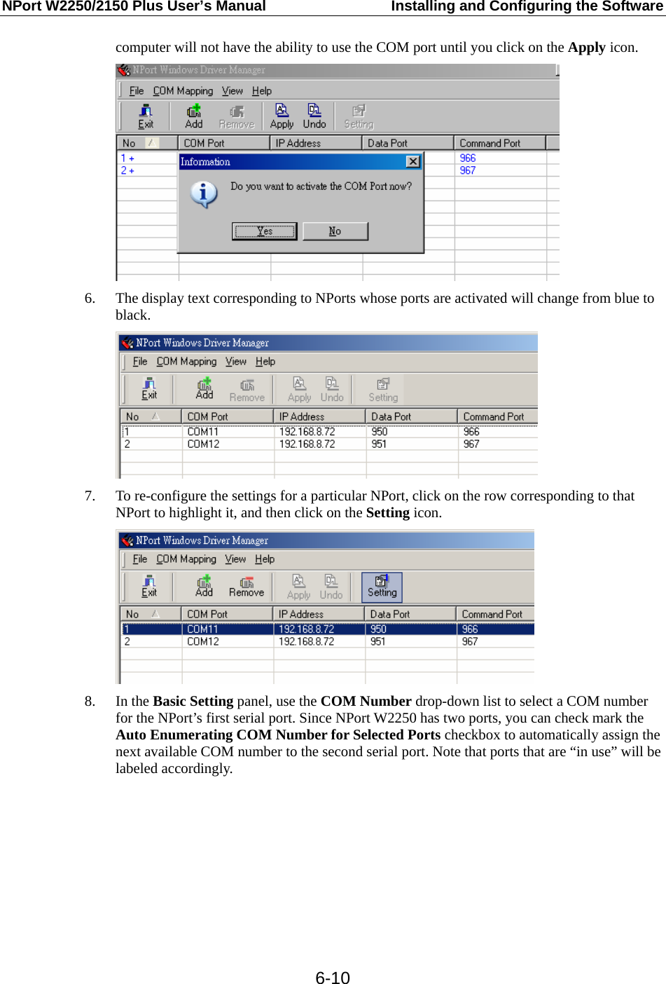
![NPort W2250/2150 Plus User’s Manual Installing and Configuring the Software 6-18 For more configuration information, look at the file moxattyd.cf, which contains detailed descriptions of the various configuration parameters. NOTE The “Device Name” depends on the OS. See the “Device Naming Rule” section for more information. Step 6: To start the moxattyd daemon after system bootup, add an entry into /etc/inittab, with the tty name you configured in moxattyd.cf. E.g., ts:2:respawn:/usr/etc/moxattyd/moxattyd –t 1 This completes the installation and configuration of MOXA TTY. Device Naming rule For UnixWare 7, UnixWare 2.1.x, and SVR4.2, use: pts/[n] For all other UNIX operating systems, use: ttyp[n] Starting moxattyd Execute the command init q or reboot your UNIX operating system. Adding an additional server Step 1: Modify the text file moxattyd.cf to add an additional server. User may use vi or any text editor to modify the file. For more configuration information, look at the file moxattyd.cf, which contains detailed descriptions of the various configuration parameters. Step 2 : Find the process id (PID) of the program moxattyd. # ps -ef | grep moxattyd Step 3: Update configuration of moxattyd program. # kill -USR1 PID (e.g., if “moxattyd” PID = 404, “kill -USR1 404”) This completes the process of adding an additional server. Upgrading the Firmware 1. Start the NPort Search Utility, right click on a specific NPort W2250/2150, and then select the Upgrade Firmware option to start upgrading the firmware.](https://usermanual.wiki/Moxa/W2250PLUS/User-Guide-802097-Page-76.png)