Moxa W311 RISC-based Ready-to-Run Wireless Embedded Computer User Manual
Moxa Inc. RISC-based Ready-to-Run Wireless Embedded Computer
Moxa >
user manual

ThinkCore W341/321/311
Hardware User’s Manual
First Edition, December 2006
www.moxa.com/product
MOXA Systems Co., Ltd.
Tel: +886-2-8919-1711
Fax: +886-2-8919-1722
Web: www.moxa.com
MOXA Technical Support
Worldwide: support@moxa.com.tw
The Americas support@moxa.com
ThinkCore W341/321/311
Hardware User’s Manual
The software described in this manual is furnished under a license agreement and may be used only in
accordance with the terms of that agreement.
Copyright Notice
Copyright © 2006 MOXA Systems Co., Ltd.
All rights reserved.
Reproduction without permission is prohibited.
Trademarks
MOXA is a registered trademark of The MOXA Group.
All other trademarks or registered marks in this manual belong to their respective manufacturers.
Disclaimer
Information in this document is subject to change without notice and does not represent a commitment on the
part of MOXA.
MOXA provides this document “as is,” without warranty of any kind, either expressed or implied, including, but
not limited to, its particular purpose. MOXA reserves the right to make improvements and/or changes to this
manual, or to the products and/or the programs described in this manual, at any time.
Information provided in this manual is intended to be accurate and reliable. However, MOXA assumes no
responsibility for its use, or for any infringements on the rights of third parties that may result from its use.
This product might include unintentional technical or typographical errors. Changes are periodically made to the
information herein to correct such errors, and these changes are incorporated into new editions of the
publication.

Table of Contents
Chapter 1 Introduction ..................................................................................................1-1
Overview.................................................................................................................................. 1-3
Package Checklist.................................................................................................................... 1-3
Product Features ...................................................................................................................... 1-4
Product Hardware Specifications............................................................................................. 1-4
System ..........................................................................................................................1-4
WLAN Communication................................................................................................ 1-5
Network Communication.............................................................................................. 1-5
Serial Communication .................................................................................................. 1-5
LEDs............................................................................................................................. 1-5
Power Requirements..................................................................................................... 1-6
Mechanical ................................................................................................................... 1-6
Environmental .............................................................................................................. 1-6
Regulatory Approvals................................................................................................... 1-6
Hardware Block Diagram ........................................................................................................ 1-6
ThinkCore W311 .......................................................................................................... 1-6
ThinkCore W321 .......................................................................................................... 1-6
ThinkCore W341 .......................................................................................................... 1-7
Chapter 2 Hardware Introduction.................................................................................2-8
Appearance .............................................................................................................................. 2-9
ThinkCore W311 .......................................................................................................... 2-9
ThinkCore W321 .......................................................................................................... 2-9
ThinkCore W341 ........................................................................................................ 2-10
Dimensions ............................................................................................................................ 2-10
ThinkCore W311 ........................................................................................................ 2-10
ThinkCore W321 ........................................................................................................ 2-11
ThinkCore W341 ........................................................................................................ 2-11
LED Indicators........................................................................................................................2-11
Reset Button........................................................................................................................... 2-12
Real Time Clock .................................................................................................................... 2-12
Chapter 3 Hardware Connection Description .............................................................3-1
Wiring Requirements ............................................................................................................... 3-1
Connecting the Power................................................................................................... 3-2
Grounding W341/321/311............................................................................................ 3-2
Connecting Data Transmission Cables .................................................................................... 3-2
Connecting to the Network........................................................................................... 3-3
Connecting to the WLAN............................................................................................. 3-3
Connecting to a Serial Device ...................................................................................... 3-3
Serial Console Port....................................................................................................... 3-4
Internal SD Socket................................................................................................................... 3-4
USB.......................................................................................................................................... 3-5
Realy Output............................................................................................................................ 3-5
Appendix A Service Information..................................................................................... A-1
MOXA Internet Services......................................................................................................... A-2
Problem Report Form .............................................................................................................A-3
Product Return Procedure....................................................................................................... A-4

1
1
Chapter 1 Introduction
The RISC-based wireless embedded computer, ThinkCore W300 Series, including W311, W321
and W341, features 802.11a/b/g WLAN, 1/2/4 RS-232/422/485 serial ports, Ethernet, and SD
socket as well as the two USB 2.0 hosts and one relay output channel for W341 into a mini size,
rugged chassis, to provide users the experience with a small package, versatile communication and
strong computing platform. To use ThinkCore W341/321/311 Series Embedded Computer, the
network device or serial device will become the wireless device and fulfill the demand to do the
numeric computing, protocol conversion, data processing and even data encryption, not only the
simply data transparent transferring. This will help user to build peer-to-peer, distributed wireless
communication embedded system, make traditional wired devices wireless, provide higher
mobility and more intelligence. It is really ideal for the diverse M2M embedded applications.
This manual covers the following topics:
Overview
¾ Package Checklist
¾ Product Features
¾ Product Hardware Specifications
¾ Hardware Block Diagrams
Hardware Introduction
¾ Appearance
¾ Dimensions
¾ LED Indicators
¾ Reset Buttons
¾ Real Time Clock
Hardware Connection Description
¾ Wiring Requirement
¾ Connecting the Power
¾ Grounding ThinkCore W341/321/311
¾ Connecting to the Network
¾ Connecting to a Serial Device
¾ Connecting to the Console Port
¾ Internal SD Socket
¾ USB Hosts
¾ Relay Output

ThinkCore W341/321/311 Hardware User’s Manual Hardware Introduction
1-2

ThinkCore W341/321/311 Hardware User’s Manual Hardware Introduction
1-3
Overview
ThinkCore W300 Series use the MOXA ART ARM9 32-bit RISC processor. Unlike the X86 CPU,
which uses a CISC design, the ARM9’s RISC design architecture and modern semiconductor
technology provide ThinkCore W341/321/311 with a powerful computing engine, but without
generating too much heat. In addition to the ARM9 core, the MOXA ART ARM9 processor
integrates UART and LAN functions, provide the extreme communication performance without
the bus bandwidth limitation as general ARM-based communication products.
Moreover, the on-board NOR Flash ROM and SDRAM give you enough storage capacity and the
additional SD socket provide the flexible storage expansion to run applications. The built-in
WLAN function supports the popular 802.11a/b/g standard, provide the transmission security
including WEP, WPA and WPA2. The backup LAN port not only provides the alternative solution
on networking but also supports the Ethernet Client capability, to make the network device to be
hooked on WLAN by easily plug-in step. Besides, the RS-232/422/485 serial ports allow you to
connect a variety of different types of serial device, make this communication platform suitable for
some of the more simple data acquisition and protocol conversion applications.
The pre-installed ready-to-run Linux-based operating system provides an open software operating
system for software program development. This means that software written for desktop PCs is
easily ported to ThinkCore W341/321/311 by using a common complier, so that you will not need
to spend time modifying existing software code. The Operating System, device drivers, and your
own software can all be stored in ThinkCore W300’s Flash memory.
Package Checklist
The ThinkCore W300 Wireless Embedded Computer Series models currently available are:
ThinkCore W311-LX
Mini RISC-based Ready-to-Run Wireless Embedded Computer with WLAN, 1 Serial Ports,
Ethernet, μClinux OS
ThinkCore W321-LX
Mini RISC-based Ready-to-Run Wireless Embedded Computer with WLAN, 2 Serial Ports,
Ethernet, SD, μClinux OS
ThinkCore W341-LX
RISC-based Ready-to-Run Wireless Embedded Computer with WLAN, 4 Serial Ports, Ethernet,
SD, USB, Relay Output, Linux OS
ThinkCore W341/321/311 Series products are shipped with the following items:
y 1 ThinkCore W341/321/311

ThinkCore W341/321/311 Hardware User’s Manual Hardware Introduction
1-4
y Quick Installation Guide
y Documentation & Software CD
y Ethernet cross-over cable: RJ45 to RJ45, 100 cm
y Console port cable
CBL-4PINDB9F-100: 4-pin header to DB9 (Female) cable, 100 cm
y Universal Power Adaptor
y Product Warranty Statement
Optional Accessories
y DK-35A DIN-Rail Mounting Kit (35 mm)
NOTE: Notify your sales representative if any of the above items are missing or damaged.
Product Features
ThinkCore W341/321/311 Series products have the following features:
y Moxa ART 32-bit ARM9 industrial communication processor
y On-board 64 MB RAM for W341, 16 MB for W321/311
y Built-in 16 MB Flash for W341, 8 MB for W321/311
y 802.11a/b/g Wireless LAN
y WEP, WPA and WPA2 encryption
y Support Infrastructure mode and Ad-Hoc mode
y Software selectable 1/2/4 RS-232/422/485 serial ports
y 50 to 921.6 Kbps, support ANY BAUD RATE
y 10/100M Ethernet for backup networking
y Support SD socket for storage expansion (W341/321 only)
y 5G continuous vibration and 50G shocking endurable
y LED indicators for System Ready, SD Status, Serial Port and WLAN signal strength
y Ready-to-Run Linux Communication Platform
y Din-rail and Wall mount installation
y Robust, Fanless Design
Product Hardware Specifications
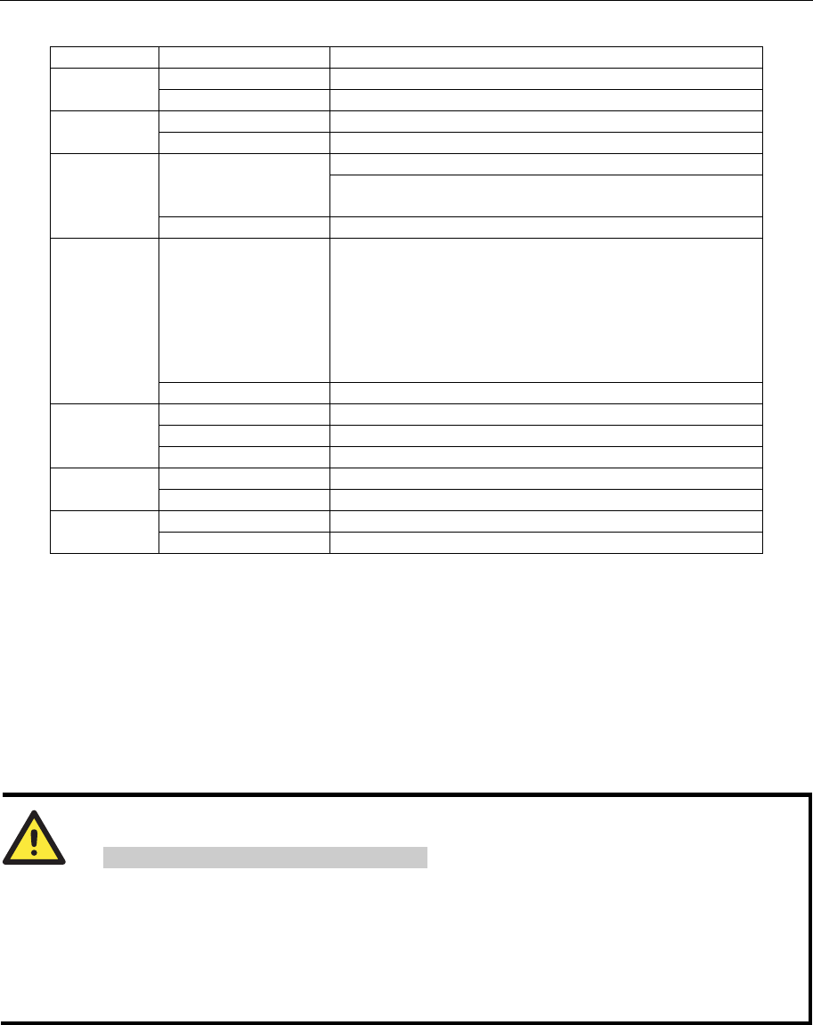
System
CPU MOXA ART ARM9 32-bit RISC CPU, 192 MHz
DRAM 64 MB for W341, 16 MB for W321/311
Flash 16 MB for W341, 8 MB for W321/311
Storage Expansion SD socket x 1 for storage expansion (W341/321 only)
USB USB 2.0 Host x 2
Realy Output Form C, SPDT x 1
Normal Switching Capacity: 2A@30VDC
Switching Power: 60W max.
Switching Voltage: 220 VDC max.
Switch Current: 2A max.

ThinkCore W341/321/311 Hardware User’s Manual Hardware Introduction
1-5
Operate Time: 4 ms @20°C
Initial Contact Resistance: 100 mohm max.
Console Port RS-232 x 1 (TxD, RxD, GND), 4-pin header output, “115200, n, 8, 1”
Button Reset button x 1, support “Reset to Factory Default”
Others RTC, buzzer, Watchdog Timer
OS Built-in Embedded Linux for W341 with MMU support
μClinux for W321/311, based on Linux Kernel 2.6
WLAN Communication
Standard Compliance 802.11a/b/g
Radio Frequency Type DSSS, CCK, OFDM
Radio Frequency Band 802.11a: 5.15~5.25GHz, 5.725~5.825GHz
802.11b/g: U.S., Europe and Japan product covering 2.4 to 2.484 GHz
Media Access Protocol Carrier Sense Multiple Access with Collision Avoidance (CSMA/CA)
Modulation 802.11a/g: OFDM (64-QAM, 16-QAM, QPSK, BPSK)
802.11b: DSSS (DBPSK, DQPSK, CCK)
Transmission Power 5.15~5.25GHz: 15dBm@ 6Mbps; 12dBm@ 54Mbps
(Typical) 5.725~5.825GHz: 15dBm@ 6Mbps; 12dBm@ 54Mbps
2.412~2.483GHz (IEEE802.11g): 17dBm@ 6Mbps; 15dBm@ 54Mbps
2.412~2.472GHz (IEEE802.11b): 18dBm@ 1~11Mbps
Receiver Sensitivity 5.15~5.25GHz: 6Mbps@ -90dBm; 54Mbps@ -72dBm
(Typical) 5.725~5.825GHz: 6Mbps@ -90dBm; 54Mbps@ -72dBm
2.412~2472G(IEEE802.11g): 6Mbps@ -90dBm; 54Mbps@ -73dBm
2.412~2.472G(IEEE802.11b): 11Mbps@ -87dBm; 1Mbps@ -94dBm
Transmission Rate 54 Mbps with auto fallback (54, 48, 36, 24, 18, 12, 11, 9, 6, 5.5, 2, 1 Mbps)
802.11b support rate: 1M, 2M, 5.5M, 11Mbps
802.11a/g support rate: 6M, 9M, 12M, 18M, 24M, 36M, 48M, 54Mbps
Transmission distance Up to 100 meters (@ 11 Mbps, in open areas)
Security WEP 64-bit/128-bit, WPA, WPA2 data encryption
Antenna Connector Reverse SMA
Antenna External 2 dbi Dipole Antenna
WLAN Mode Infrastructure, Ad-Hoc
Network Communication
LAN Auto-sensing 10/100Mbps x 1, RJ45
Protection built-in 1.5KV magnetic isolation protection
Serial Communication
Serial Port One software–selectable RS-232/422/485 port for W311, DB9 connector
Two software–selectable RS-232/422/485 port for W321, DB9 connector
Four software–selectable RS-232/422/485 port for W341, DB9 connector
Protection built-in 15KV ESD protection for all signals
Data bits 5, 6, 7, 8
Stop bits 1, 1.5, 2
Parity None, Even, Odd, Space, Mark
Flow Control RTS/CTS, XON/XOFF, RS-485 ADDCTM
Speed 50 bps to 921.6 Kbps, support any baud rate
LEDs

ThinkCore W341/321/311 Hardware User’s Manual Hardware Introduction
1-6
System Ready, SD (W341/321 only)
WLAN Enable, Signal Strength (5 LEDs)
LAN 10M/Link (on connector), 100M/Link (on connector)
Serial TxD, RxD
Power Requirements
Power Input 12 to 48V
Power Consumption W311: 250mA@12VDC, 3W
W321: 300mA@12VDC, 3.6W
W341: 540mA@12VDC, 6.5W
Mechanical
Dimension (WxDxH) W311: 67 x 100.4 x 22 mm (without wall mount ear and antenna)
W321: 77 x 111 x 26 mm (without wall mount ear and antenna)
W341: 150 x 100 x 38 mm (without wall mount ear and antenna)
Antenna 110 mm
Construction Material W311: aluminum, 1 mm
W321: aluminum, 1 mm
W341: aluminum, 1 mm / SECC, 1 mm for rear panel
Mounting DIN-rail, wall mounting
Environmental
Operating Temperature -10 to 60°C (14 to 140°F), 5 to 95% RH
Storage Temperature -20 to 80°C (-4 to 176°F), 5 to 95% RH
Regulatory Approvals
EMC FCC, CE (Class A)
Safety TÜV, UL, cUL
Others RoHS, CRoHS, WEEE
Warranty 5 years
Hardware Block Diagram
The following block diagrams show the layout of ThinkCore W341/321/311s’ internal function
blocks and components
ThinkCore W311
ThinkCore W321

ThinkCore W341/321/311 Hardware User’s Manual Hardware Introduction
1-7
ThinkCore W341

ThinkCore W341/321/311 Hardware User’s Manual Hardware Introduction
2-8
2
2
Chapter 2 Hardware Introduction
In this chapter, we will introduce the detail of ThinkCore W341/321/311 hardware, includes the
following sections.
Appearance
Dimensions
LED Indicators
Reset Buttons
Real Time Clock

ThinkCore W341/321/311 Hardware User’s Manual Hardware Introduction
2-9
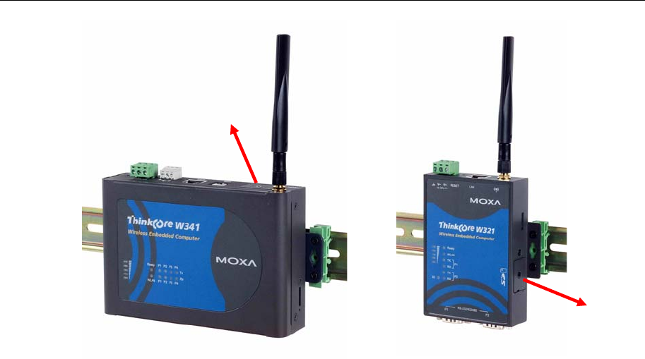
Appearance
The view of ThinCore W341/321/311 Series are shown in the following figures. Please notice
W311 doesn’t support the SD expansion function.
ThinkCore W311
Rear View
Top View
Front View
ThinkCore W321
Rear View
Top View
Front View

ThinkCore W341/321/311 Hardware User’s Manual Hardware Introduction
2-10
ThinkCore W341
Rear View
Top View
Front View
Dimensions
The dimensions of ThinkCore W341/321/311 are shown in the following figures.
ThinkCore W311

ThinkCore W341/321/311 Hardware User’s Manual Hardware Introduction
2-11
ThinkCore W321
ThinkCore W341
LED Indicators
The following table explains the function of the LED indicators located on ThinkCore
W341/321/311, please notice W311 doesn’t support SD expansion function, there is no SD LED
on it.
ThinkCore W341/321/311 Hardware User’s Manual Hardware Introduction
2-12
LED Name LED Color LED Function
Green Power is on and functioning normally Ready
Off Power off or any other power error
Green SD card is detected SD
Off No SD card detected
ON: WLAN is ready Green
Blinking: WLAN IP conflict or DHCP server no
response
WLAN
OFF WLAN is not ready or function error
Green Lighting LED number means different signal strength
status.
5: Excellent
4: Very good
3: Good
2: Fair
1: Bad
Signal
Strength
(5 LEDs)
Off No signal or WLAN connection failed
Orange 10Mbps Ethernet link
Green 100Mbps Ethernet link
LAN
Off Disconnected or short circuit
Green Serial port 1~4 is transmitting data TxD1~4
Off Serial port 1~4 is not transmitting data
Yellow Serial port 1~4 is receiving data RxD1~4
Off Serial port 1~4 is not receiving data
Reset Button
Press the “RESET” button continuously for more than 5 seconds to load the factory default
configuration. After loading the factory defaults, the system will reboot automatically. The System
Ready LED will blink for the first 5 seconds. We recommend that you only use this function if the
software is not working properly. To reset the Linux system software, always use the software
reboot command (reboot) to protect the integrity of data that is in the process of being transmitted.
The reset button is NOT designed to Hard Reboot ThinkCore W300 Series products.
ATTENTION
Reset to Default preserves user’s data
Resetting to factory defaults will NOT format the user directory and erase the user’s data. Pressing
this Reset button will only load the configuration file. All files in the /etc directory will revert to
their factory defaults, but other User Data will still exist in the Flash ROM.
This function only takes effect when the user directory is working correctly. If the user directory
has crashed, the kernel will automatically load the factory defaults.
Real Time Clock
ThinkCore W341/321/311’s real time clock is powered by a lithium battery. We strongly

ThinkCore W341/321/311 Hardware User’s Manual Hardware Introduction
2-13
recommend that you do not replace the lithium battery without the help of MOXA’s support team.
If the battery needs to be changed, contact the MOXA RMA service team for RMA service.
ATTENTION
The battery may explode if replaced by an incorrect type. To avoid this potential danger, always be
sure to use the correct type of battery.

ThinkCore W341/321/311 Hardware User’s Manual Hardware Introduction
2-14

3
3
Chapter 3 Hardware Connection Description
This chapter describes how to connect ThinkCore W341/321/311 hardware, includes information
about the power connecting, wiring and function introduction.
This chapter covers the following topics:
Wiring Requirement
Connecting the Power
Grounding ThinkCore W341/321/311
Connecting to the Network
Connecting to a Serial Device
Connecting to the Console Port
Internal SD Socket
USB Hosts
Relay Output
Wiring Requirements
This section describes how to connect ThinkCore W341/321/311 to serial devices.
You should heed the following common safety precautions before proceeding with the installation
of any electronic device:
y Use separate paths to route wiring for power and devices. If power wiring and device wiring
paths must cross, make sure the wires are perpendicular at the intersection point.
NOTE: Do not run signal or communication wiring and power wiring in the same wire
conduit. To avoid interference, wires with different signal characteristics should be routed
separately.
y Use the type of signal transmitted through a wire to determine which wires should be kept
separate. The rule of thumb is that wiring that shares similar electrical characteristics can be
bundled together.
y Keep input wiring and output wiring separate.
y It is advisable to label the wiring to all devices in the system.
UC-7112/7110 User’s Manual UC Finder
3-2
ATTENTION
Safety First!
Be sure to disconnect the power cord before installing and/or wiring your ThinkCore
W341/321/311.
Wiring Caution!
Calculate the maximum possible current in each power wire and common wire. Observe all
electrical codes dictating the maximum current allowable for each wire size.
If the current goes above the maximum ratings, the wiring could overheat, causing serious
damage to your equipment.
Temperature Caution!
Be careful when handling ThinkCore W341/321/311. When plugged in, ThinkCore
W341/321/311’s internal components generate heat, and consequently the outer casing may feel
hot to the touch.
Connecting the Power
Connect the “live-wire” end of the 12-48 VDC power adapter to ThinkCore W341/321/311’s
terminal block. If the power is properly supplied, the “Ready” LED will glow a solid green after a
25 to 30 second delay.
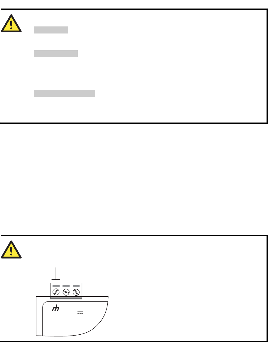
Grounding W341/321/311
Grounding and wire routing help limit the effects of noise due to electromagnetic interference
(EMI). Run the ground wire from the ground screw to the grounding surface prior to connecting
devices.
ATTENTION
This product should be mounted to a well-grounded mounting surface such as a metal panel.
V+V-
SG
12-48V
SG: The Shielded Ground (sometimes called
Protected Ground) contact is the left most contact
of the 3-pin power terminal block connector when
viewed from the angle shown here. Connect the
SG wire to an appropriate grounded metal surface.
Connecting Data Transmission Cables
This section describes how to connect ThinkCore W341/321/311 to the network, serial devices,
UC-7112/7110 User’s Manual UC Finder
3-3
and serial COM terminal.
Connecting to the Network
Connect one end of the Ethernet cable to ThinkCore W341/321/311’s 10/100M Ethernet port and
the other end of the cable to the Ethernet network. If the cable is properly connected, ThinkCore
W341/321/311 will indicate a valid connection to the Ethernet in the following ways:
y The top-right LED on the connector glows a solid green when connected to a 100 Mbps
Ethernet network.
y The top-left LED on the connector glows a solid orange when connected to a 10 Mbps
Ethernet network.
y The LEDs will flash when Ethernet packets are being transmitted or received.
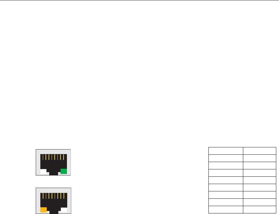
The 10/100 Mbps Ethernet LAN port use 8-pin RJ45 connectors. Pinouts for these ports are given
in the following diagram.
18
The LED indicator in the lower right corner glows
a solid green color when the cable is properly
connected to a 100 Mbps Ethernet network. The
LED will flash on and off when Ethernet packets
are being transmitted or received.
18
The LED indicator in the lower left corner glows a
solid orange color when the cable is properly
connected to a 10 Mbps Ethernet network. The
LED will flash on and off when Ethernet packets
are being transmitted or received.
Pin Signal
1 ETx+
2 ETx-
3 ERx+
4 ---
5 ---
6 ERx-
7 ---
8 ---
Connecting to the WLAN
ThinkCore W341/321/311 is the WLAN ready wireless embedded computer, embeds an 802.11
a/b/g WLAN module inside and support the WEP, WPA and WPA2 data encryption. To make sure
the WLAN function works normally, please enter the system first to do the associated WLAN
configuration via fixed network or serial console, you may refer to the OS operating user’s manual
for the further detail.
Connecting to a Serial Device
Connect the serial cable between ThinkCore W341/321/311 and the serial device(s).
Serial ports P1 to P4 use male DB9 connectors, and can be configured for RS-232/422/485 by
software. The pin assignments are shown in the following table:
DB9 Male Port
RS-232/422/485 Pinouts
UC-7112/7110 User’s Manual UC Finder
3-4
12345
6789
Pin RS-232 RS-422 RS-485
(4-wire) RS-485
(2-wire)
1 DCD TxDA(-) TxDA(-) ---
2 RxD TxDB(+) TxDB(+) ---
3 TxD RxDB(+) RxDB(+) DataB(+)
4 DTR RxDA(-) RxDA(-) DataA(-)
5 GND GND GND GND
6 DSR --- --- ---
7 RTS --- --- ---
8 CTS --- --- ---
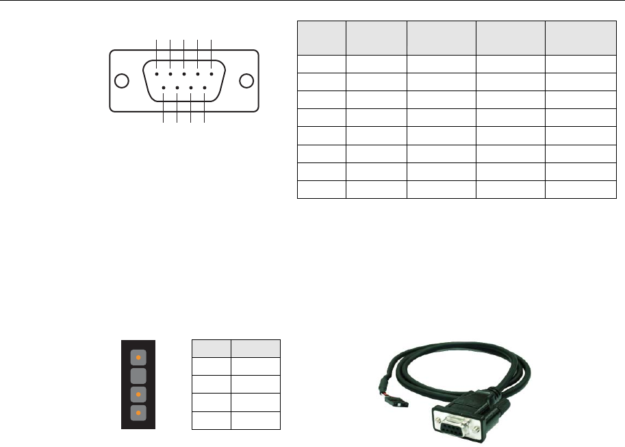
Serial Console Port
The serial console port is a 4-pin pin-header RS-232 port. It is designed for serial console
terminals, which are useful for identifying the ThinkCore W341/321/311 boot up message.
Serial Console Port & Pinouts
Serial Console Cable
4
3
2
1
Pin Signal
1 TxD
2 RxD
3 NC
4 GND
Internal SD Socket
ThinkCore W341/321 provides an internal SD socket for storage expansion. It allows users to plug
in a Secure Digital (SD) memory card compliant with the SD 1.0 standard for up to 1 GB of
additional memory space. To install an additional SD card, you must first remove the W341/321’s
SD outer cover to access the slot. The internal SD socket is located at the ThinkCore W341/321
bottom board; you can find the SD plug-in slot at the lower right side of W321 and top right side
of W341 shown as figures. Plug the SD card into the socket directly and remember to press the SD
card first if you want to take it out.
UC-7112/7110 User’s Manual UC Finder
3-5
USB
ThinkCore W341 provides two USB 2.0 hosts, which supports the ability to connect a flash disk or
2.5 inch hard drive for storing large amounts of data.
Realy Output
ThinkCore W341 provides a relay output channel. There is a 3-pin terminal
block for this relay output connection. The pinouts for the relay output
channel are shown in the figure.
SD Socket
Outer Cover
SD Socket
Outer Cover

UC-7112/7110 User’s Manual UC Finder
3-6

A
A
Appendix A Service Information
This appendix shows you how to contact MOXA for information about this and other products,
and how to report problems.
The following topics are covered in this appendix:
MOXA Internet Services
Problem Report Form
Product Return Procedure

UC-7112/7110 User’s Manual Service Information
A-2
MOXA Internet Services
Customer satisfaction is our number one concern, and to ensure that customers receive the full
benefit of our products, Moxa Internet Services has been set up to provide technical support, driver
updates, product information, and user’s manual updates.
The following services are provided
E-mail for technical support................................support@moxa.com
World Wide Web (WWW) Site for product information:
.............................http://www.moxa.com

UC-7112/7110 User’s Manual Service Information
A-3
Problem Report Form
MOXA ThinkCore W341/321/311 Series
Customer name:
Company:
Tel: Fax:
Email: Date:
1. Moxa Product: ThinkCore W341 ThinkCore W321 ThinkCore W311
2. Serial Number: _________________
Problem Description:Please describe the problem clearly. Include as many details as you can. This will help us
reproduce the problem, and expedite the repair of your product.

UC-7112/7110 User’s Manual Service Information
A-4
Product Return Procedure
For product repair, exchange, or refund, the customer must:
Provide evidence of original purchase.
Obtain a Product Return Agreement (PRA) from the sales representative or dealer.
Fill out the Problem Report Form (PRF). Include as much detail as possible for a shorter
product repair time.
Carefully pack the product in an anti-static package, and send it, pre-paid, to the dealer. The
PRA should be visible on the outside of the package, and include a description of the problem,
along with the return address and telephone number of a technical contact.
FEDERAL COMMUNICATIONS COMMISSION INTERFERENCE STATEMENT
This equipment has been tested and found to comply with the limits for a Class B digital
device, pursuant to Part 15 of the FCC Rules. These limits are designed to provide
reasonable protection against harmful interference in a residential installation. This
equipment generates, uses and can radiate radio frequency energy and, if not installed
and used in accordance with the instructions, may cause harmful interference to radio
communications. However, there is no guarantee that interference will not occur in a
particular installation. If this equipment does cause harmful interference to radio or
television reception, which can be determined by turning the equipment off and on, the
user is encouraged to try to correct the interference by one or more of the following
measures:
– Reorient or relocate the receiving antenna.
– Increase the separation between the equipment and receiver.
– Connect the equipment into an outlet on a circuit different from that to which the
receiver is connected.
– Consult the dealer or an experienced radio/TV technician for help.
CAUTION:
Any changes or modifications not expressly approved by the party responsible for
compliance could void the user's authority to operate the equipment.
This device complies with Part 15 of the FCC Rules. Operation is subject to the following
two conditions:
(1) This device may not cause harmful interference and
(2) This device must accept any interference received, including interference that may
cause undesired operation.
FCC RF Radiation Exposure Statement
This equipment complies with FCC RF radiation exposure limits set forth for an
uncontrolled environment.
RF exposure warning
This equipment must be installed and operated in accordance with provided instructions and
the antenna(s) used for this transmitter must be installed to provide a separation distance of at
least 20 cm from all persons and must not be co-located or operating in conjunction with any
other antenna or transmitter. End-users and installers must be provide with antenna installation
instructions and transmitter operating conditions for satisfying RF exposure compliance.