Moxa W321-W311 RISC-based Ready-to-Run Wireless Embedded Computer User Manual W311 321 341 Hardware User s Manual v6
Moxa Inc. RISC-based Ready-to-Run Wireless Embedded Computer W311 321 341 Hardware User s Manual v6
Moxa >
Contents
- 1. User Manual
- 2. User Manual Rev
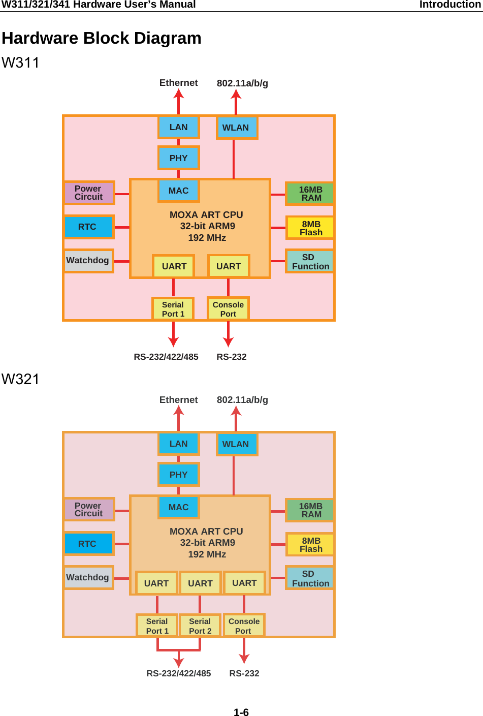
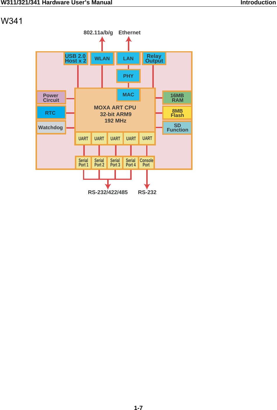
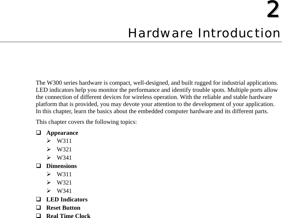
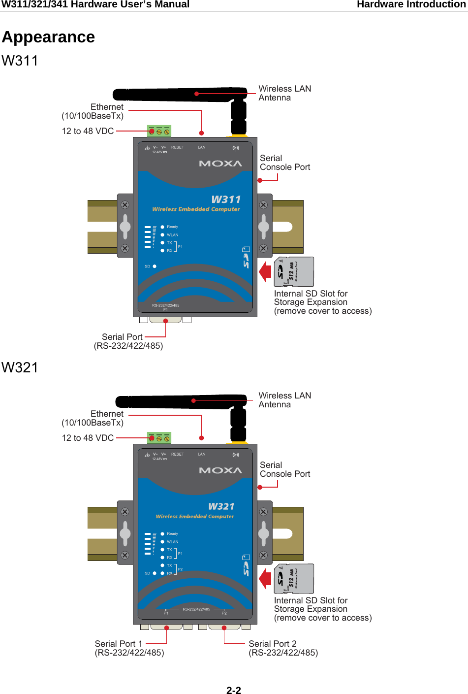
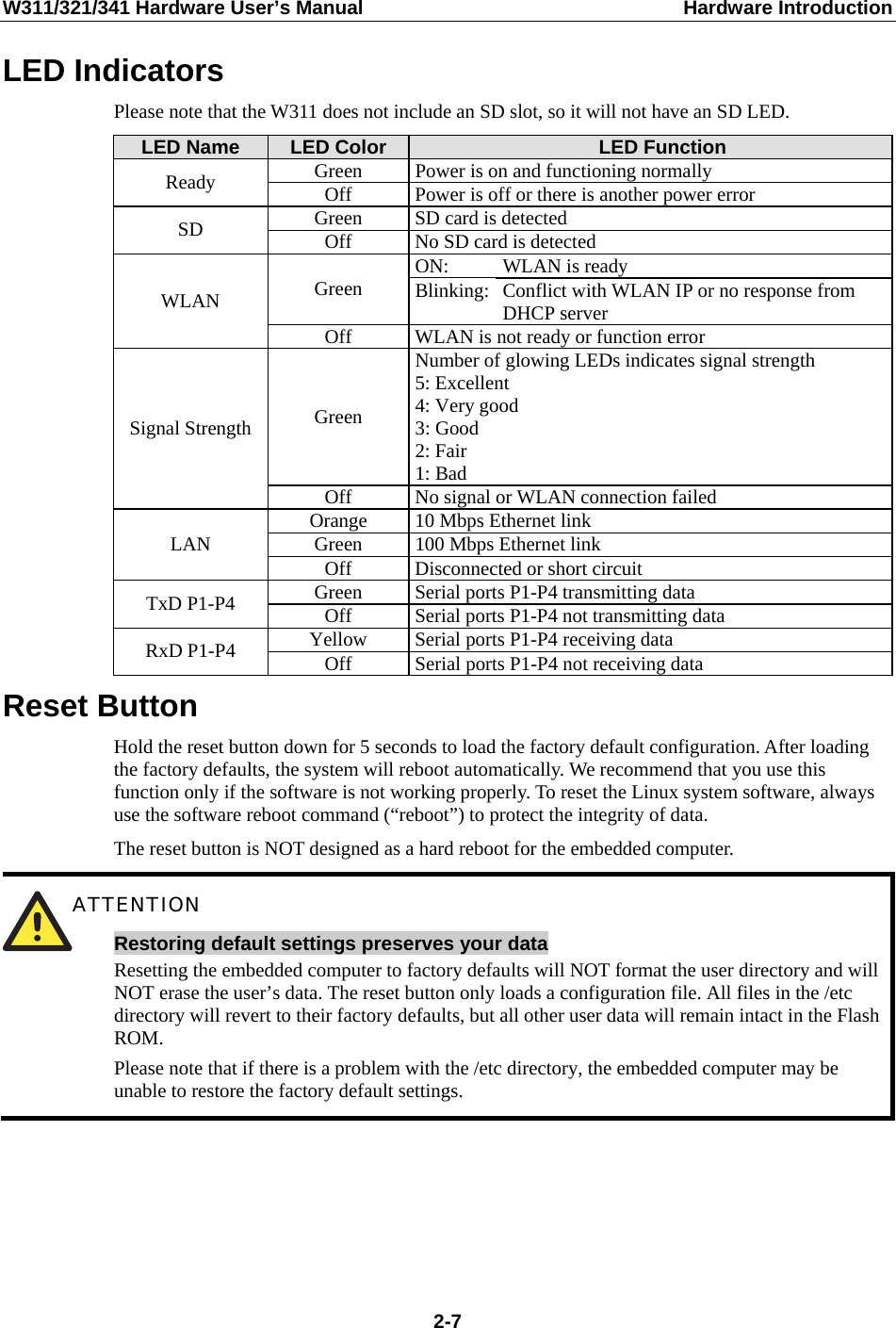
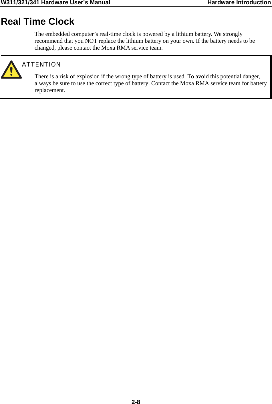
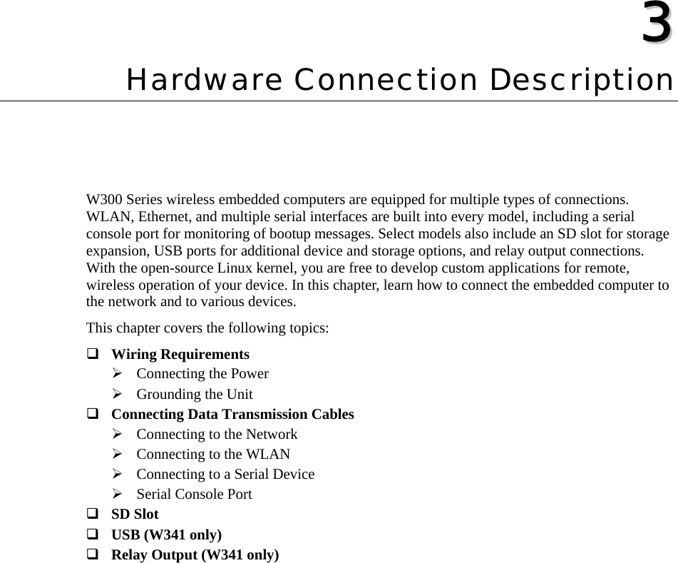
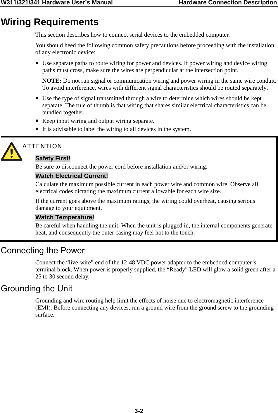
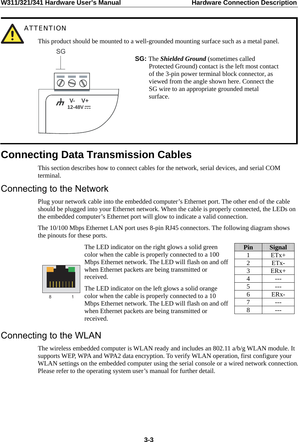
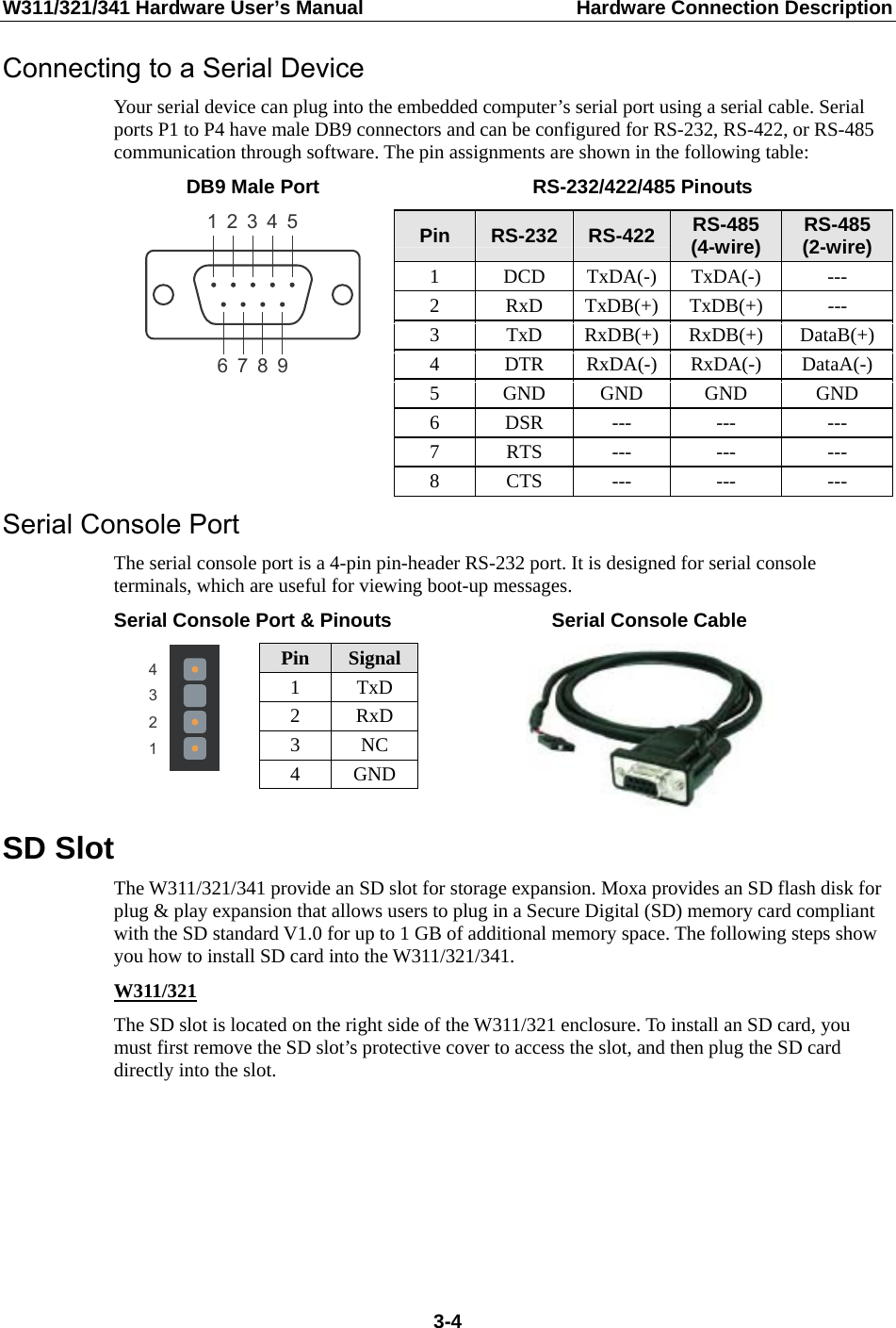
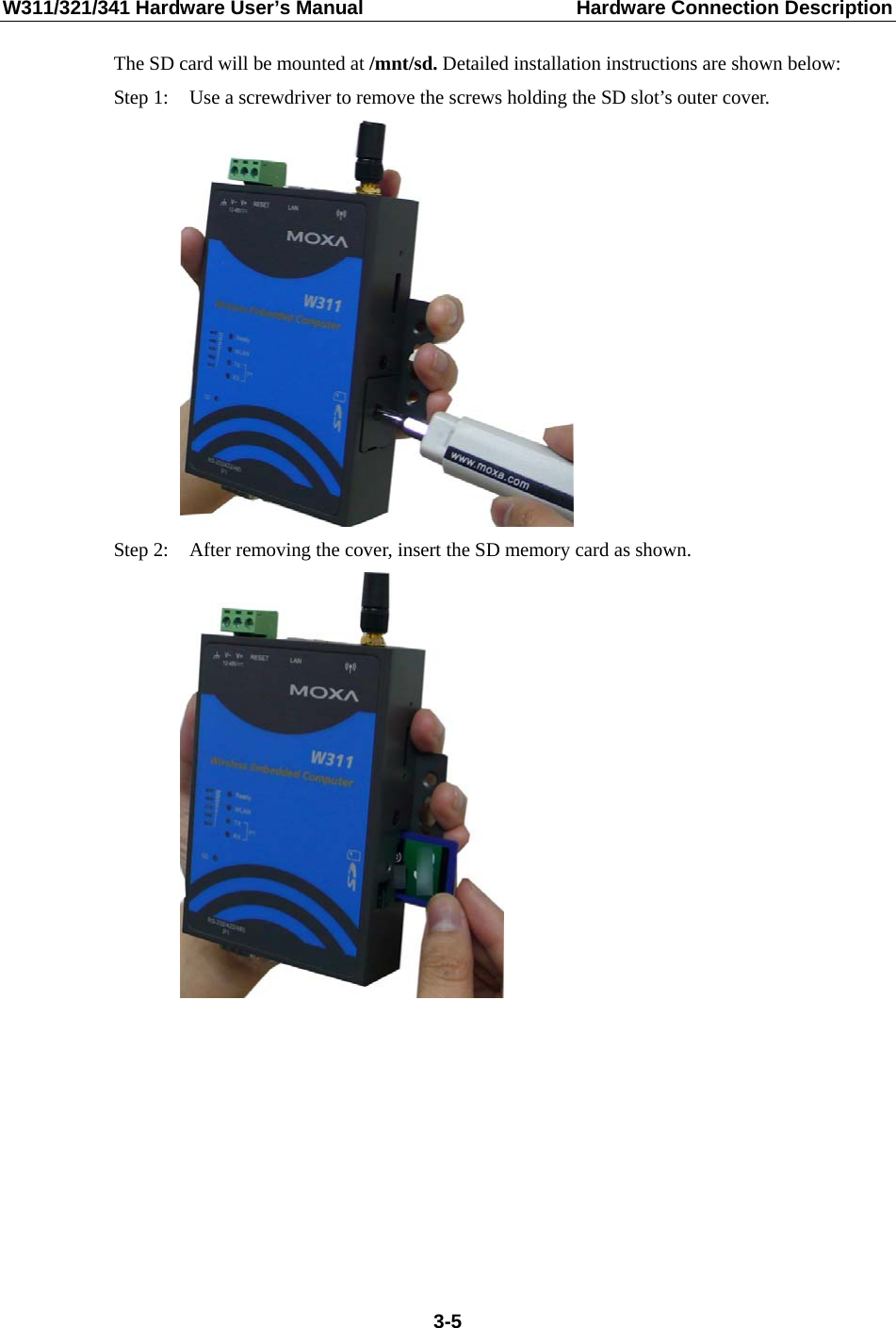
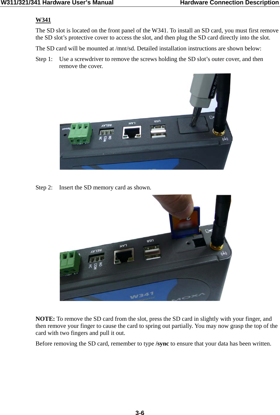
User Manual