Moxa WAPN001 Moxa IEEE 802.11a/b/g/n MiniPCI Module User Manual WAPN001
Moxa Inc. Moxa IEEE 802.11a/b/g/n MiniPCI Module WAPN001
Moxa >
(WAPN001) UserMan

Moxa IEEE 802.11a/b/g/n MiniPCI Module
WAPN001 User’s Manual
www.moxa.com
First Edition, July 2010
© 2009 Moxa Inc. All rights reserved.
Reproduction without permission is prohibited.

WAPN001 User’s Manual
The hardware and software described in this manual is furnished under a license agreement and may be used
only in accordance with the terms of that agreement.
Copyright Notice
Copyright © 2009 Moxa Inc.
All rights reserved.
Reproduction without permission is prohibited.
Trademarks
MOXA is a registered trademark of Moxa Inc.
All other trademarks or registered marks in this manual belong to their respective manufacturers.
Disclaimer
Information in this document is subject to change without notice and does not represent a commitment on the
part of Moxa.
Moxa provides this document “as is,” without warranty of any kind, either expressed or implied, including, but
not limited to, its particular purpose. Moxa reserves the right to make improvements and/or changes to this
manual, or to the products and/or the programs described in this manual, at any time.
Information provided in this manual is intended to be accurate and reliable. However, Moxa assumes no
responsibility for its use, or for any infringements on the rights of third parties that may result from its use.
This product might include unintentional technical or typographical errors. Changes are periodically made to the
information herein to correct such errors, and these changes are incorporated into new editions of the
publication.
Technical Support Contact Information
www.moxa.com/support
Moxa Americas:
Toll-free: 1-888-669-2872
Tel: +1-714-528-6777
Fax: +1-714-528-6778
Moxa China (Shanghai office):
Toll-free: 800-820-5036
Tel: +86-21-5258-9955
Fax: +86-10-6872-3958
Moxa Europe:
Tel: +49-89-3 70 03 99-0
Fax: +49-89-3 70 03 99-99
Moxa Asia-Pacific:
Tel: +886-2-8919-1230
Fax: +886-2-8919-1231
Table of Contents
Chapter 1 Introduction
Overview
Features
Specification
Chapter 2 Getting Started
Module Layout
Block Diagram
Hardware Installation
Software Installation

WAPN001 User’s Manual Introduction
1
1
Chapter 1 Introduction
The following topics are covered in this chapter:
Overview
Features
Specifications

WAPN001 User’s Manual Introduction
Overview
WAPN001Mini-PCI Module is designed to provide wireless communication for all wireless device based
systems. It communicates via the standard 802.11a/b/g/n protocols. The WAPN001 uses the AR9220 wireless
chipset from Atheros. This module is connected to the PCI bus through a Mini-PCI connector and special
circuitry to allow for compatibility with either 3.3V or 5V PCI signaling.
.
Features
z Dynamic frequency selection (DFS) in required 5-GHz bands
z All-CMOS MIMO solution interoperable with IEEE 802.11a/b/g/n WLANs
z 2x2 MIMO technology improves effective throughput and range over existing 802.11a/b/g products
z Supports spatial multiplexing, cyclic-delay diversity (CDD), and maximal ratio combining (MRC)
z 2.4/5 GHz WLAN MAC/BB processing
z BPSK, QPSK, 16 QAM, 64 QAM, DBPSK,DQPSK, and CCK modulation schemes
z Data rates of up to 144.4 Mbps for 20 MHz channels and 300 Mbps for 40 MHz channels
z Wireless multimedia enhancements quality of service support (QoS)
z 802.11e-compatible bursting
z WEP, TKIP, and AES hardware encryption
z 337-pin, 12 mm x 12 mm BGA package
z Case temperature 85°C

WAPN001 User’s Manual Introduction
Specification
Features WAPN001
Chipset Atheros AR9220
Baseband Processor
(BBP) ˙ DSS with DBPSK, DQPSK, CCK
˙ OFDM with BPSK, QPSK, 16QAM, 64QAM
˙ 802.11b: CCK@11/5.5 Mbps, DQPSK@2 Mbps, DBPSK@11 Mbps
˙ 802.11a/g: 64QAM@54/48 Mbps, 16QAM@36/24 Mbps, QPSK@18/12 Mbps
BPSK@9/6 Mbps
˙ 802.11n: 64QAM@300 to BPSK@6.5 Mbps (multiple rates supported)
security engine WEP64,WEP128, WEP256, AES-CCM, TKIP ,WPS
Bus Interface Mini PCI standard bus complaint
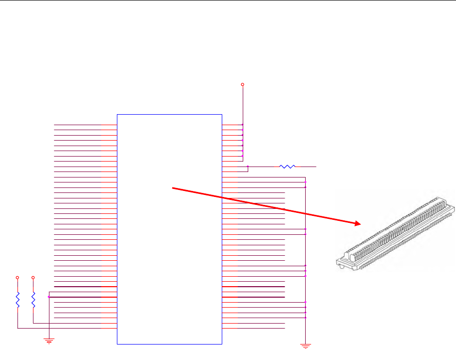
Connectors Defined BTB connector is using 2x40 pins header, and Support Mini-PCI standard.
Power requirement 1.2V +/-5%
1.8V +/-5%
3.3V +/-10%
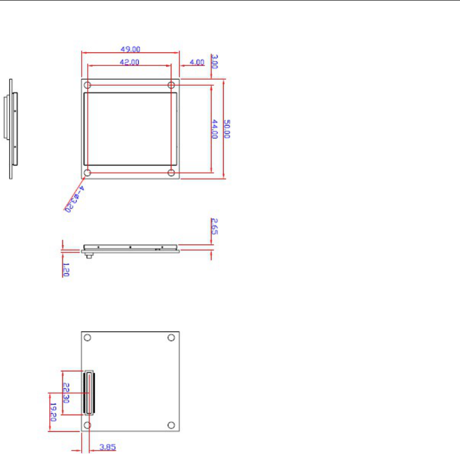
Dimension 50mm x 49mm x 1.2mm
Weight 15g
Operating
Temperature -40 to +80 ℃
Storage
Temperature: -40 to +150℃

2
2
Chapter 2 Getting Started
This chapter covers the module layout, and block diagram, hardware installation of the WAPN001. Software
installation is covered in the next chapter.
The following topics are covered:
Module Layout
Block Diagram
Hardware Installation
Software Installation
WAPN001 User’s Manual Getting Started
Module Layout
WAPN001 User’s Manual Getting Started
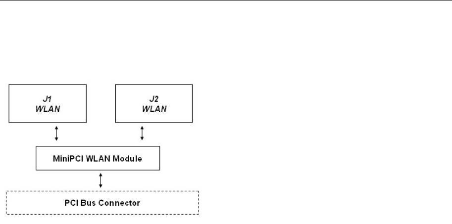
Block Diagram
Below is a block diagram of the WAPN001. Primary board components are in bold, while external connections
are italicized.
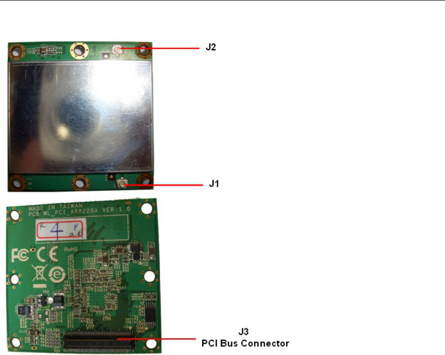
WAPN001 User’s Manual Getting Started
Connector Locations
WAPN001 User’s Manual Getting Started
MiniPCI Bus Connector PIN Assignments
AD30
3.3V_CON
PCI_INT_L
PCI_GNT_L
AD31
PCI_CBE2_L
AD1
PCI_CBE3_L
AD3
PCI_PME_L
PCI_CBE1_L
AD5
PCI_RST_L
AD7
AD0
AD8
MPC I_12
MPC I_11
AD4
AD10
AD2
RF_DISABLE
AD6
PCI_CLK
PCI_REQ_L
AD9
AD12
PCI_CBE0_L
AD14
AD13
AD11
PCI_PERR_L
PCI_DEVSEL_L
AD15
PCI_SERR_L
AD17
R9
R0603
187
GPIO_5
AD19
3.3V
AD21
PCI_TRDY_L
PCI_STOP_L
PCI_IRDY_LAD23
AD16 PCI_CLKRUN_L
PCI_FRAME_L
R8
R0603
187
3.3V
AD18
J1
DEFINE BOARD EDGE
3.3V-3 6
INTA# 34
GND-7 72
3.3VAUX 18
CLK 30
RST# 28
GND-5 60
3.3V-4 8
REQ# 36
GNT# 38
3.3V-6 12
GND-11 22
AD31
63
PME# 68
AD29
59
GND-13 26
AD30
61
AD27
55
3.3V-5 10
AD25
51
AD28
57
AD26
53
CBE3#
75
AD24
49 AD23
47
IDSEL 66
GND-4 58
GND-15 44
AD21
43
AD22
45
AD19
39
AD20
41
GND-3 56
PAR 46
AD17
35
AD18
37
CBE2#
73
AD16
33
IRDY# 48
GND-12 24
3.3V 2
FRAME# 52
CLKRUN# 32
TRDY# 50
SERR# 62
STOP# 54
GND-8 74
3.3V-7 14
PERR# 40
DEVSEL# 64
CBE1#
71
GND-14 42
AD14
29
AD15
31
AD13
27 AD12
25 AD11
23 AD10
21
GND-9 76
AD9
19 AD8
17
CBE0#
69
AD7
15 3.3V-8 16
3.3V-2 4
AD6
13 AD5
11 AD4
9
AD2
5
AD3
7
AD0
1
AD1
3
GND-6 70
LED1-GRNN 78
GND-1
67 GND
65
3.3VAUX-1 20
LED1-GRNP
77
LED2-YELP
79 LED2-Y ELN 80
PCI_PAR
AD25
3.3V_AUX
AD27
AD22
AD20
AD29
AD24
MPCI_14
PCI_IDSEL_L
AD28
AD26
R26
R0402
R

WAPN001 User’s Manual Getting Started
Hardware Installation
The WAPN001 can be installed into all Moxa wireless system board series. It can be located
below the CPU.
Step for Installation
1. Attach the WLAN antenna to connector J1.
2. If using 2nd WLAN antenna, attach it to connector J2.
3. Install the WAPN001 miniPCI card on the system board. Apply pressure to both bus
connectors and gently press the board onto the stack. The board should slide into the matching
bus connectors. Do not attempt to force the board, as this can lead to bent/broken pins.
4. Screw on the WAPN001 miniPCI card.
5. If any power boards are to be stacked above the WAPN001, install them.
6. Screw on the all the necessary chassis.
Software Installation
After physically installing the WAPN001, your operating system must be configured to recognize
the new system board.
Step for Installation
1. Apply power to the system board.
2. Connect system board and PC with Ethernet cable.
3. Open a browser and type: 192.168.127.253 to open the system login webpage.
4. Login the webpage with default password: root in order to verify that all of the hardware is
install properly.

WAPN001 User’s Manual Getting Started
Federal Communication Commission Interference
Statement
This equipment has been tested and found to comply with the limits for a Class B digital device, pursuant to Part
15 of the FCC Rules. These limits are designed to provide reasonable protection against harmful interference in a
residential installation. This equipment generates, uses and can radiate radio frequency energy and, if not
installed and used in accordance with the instructions, may cause harmful interference to radio communications.
However, there is no guarantee that interference will not occur in a particular installation. If this equipment does
cause harmful interference to radio or television reception, which can be determined by turning the equipment
off and on, the user is encouraged to try to correct the interference by one of the following measures:
- Reorient or relocate the receiving antenna.
- Increase the separation between the equipment and receiver.
- Connect the equipment into an outlet on a circuit different from that to which the receiver is connected.
- Consult the dealer or an experienced radio/TV technician for help.
FCC Caution:
To assure continued compliance, (example - use only shielded interface cables when connecting to computer or
peripheral devices) any changes or modifications not expressly approved by the party responsible for compliance
could void the user's authority to operate this equipment.
This device complies with Part 15 of the FCC Rules. Operation is subject to the following two conditions:
(1) This device may not cause harmful interference, and
(2) This device must accept any interference received, including interference that may cause undesired operation.
IMPORTANT NOTE:
This module is restricted to mobile configuration. To comply with FCC RF exposure compliance requirements,
the antenna used for this transmitter must be installed to provide a separation distance of at least 20 cm from all
persons and must not be co-located or operating in conjunction with any other antenna or transmitter. This
transmitter module must not be co-located or operating in conjunction with any other antenna or transmitter
CAUTION:
Any changes or modifications not expressly approved by the grantee of this device could void the user's
authority to operate the equipment.
This device is operation in 5.15 – 5.25GHz frequency range, then restricted in indoor use only.
End Product Labeling
This transmitter module is authorized only for use in device where the antenna may be installed such that 20cm
may be maintained between the antenna and users. The final end product must be labeled in a visible area with
the following: "Contains FCC ID: SLE-WAPN001 ”