Moxa WAPN010 MOXA IEEE 802.11b/g/n 4X4 module User Manual
Moxa Inc. MOXA IEEE 802.11b/g/n 4X4 module Users Manual
Moxa >
Users Manual

Moxa 802.11 b/g/n
WAPN010 User’s Manual
www.moxa.com
First Edition, April 2018
2018 Moxa Inc. All rights reserved.
Reproduction without permission is prohibited.

WAPN010 User’s Manual
The hardware and software described in this manual is furnished under a license agreement and may be used
only in accordance with the terms of that agreement.
Copyright Notice
Copyright 2018 Moxa Inc.
All rights reserved.
Reproduction without permission is prohibited.
Trademarks
MOXA is a registered trademark of Moxa Inc.
All other trademarks or registered marks in this manual belong to their respective manufacturers.
Disclaimer
Information in this document is subject to change without notice and does not represent a commitment on the
part of Moxa.
Moxa provides this document “as is,” without warranty of any kind, either expressed or implied, including, but
not limited to, its particular purpose. Moxa reserves the right to make improvements and/or changes to this
manual, or to the products and/or the programs described in this manual, at any time.
Information provided in this manual is intended to be accurate and reliable. However, Moxa assumes no
responsibility for its use, or for any infringements on the rights of third parties that may result from its use.
This product might include unintentional technical or typographical errors. Changes are periodically made to
the information herein to correct such errors, and these changes are incorporated into new editions of the
publication.
Technical Support Contact Information
www.moxa.com/support
Table of Contents
Chapter 1 Introduction
Overview
Specification
Chapter 2 Getting Started
Module Layout
Block Diagram
Hardware Installation
Software Installation

WAPN010 User’s Manual Introduction
1
Chapter 1
The following topics are covered in this chapter:
Overview
Specifications
Introduction

WAPN010 User’s Manual Introduction
Overview
WAPN010 PCIe module is designed to provide wireless communication for Moxa industrial wireless products.
It communicates via the standard 802.11 b/g/n protocols on standard 2.4GHz channels. The WAPN010 uses
the QCA99X4 SoC Wireless chipset from Qualcomm.
Specification
Features
WAPN008
Chipset
Qualcomm QCA99X4
Baseband
Processor (BBP)
- DSSS with DBPSK, DQPSK, CCK
- OFDM with BPSK, QPSK, 16QAM, 64QAM
- 802.11b: CCK @ 11/5.5 Mbps, DQPSK @ 2 Mbps, DBPSK @ 11 Mbps
- 802.11 g: 64QAM @ 54/48 Mbps, 16QAM @ 36/24 Mbps, QPSK @ 18/12 Mbps,
BPSK @ 9/6 Mbps
- 802.11n: 64QAM @ 300 Mbps to BPSK @ 6.5 Mbps (multiple rates supported)
security engine
- 64-bit and 128-bit WEP encryption, WPA /WPA2-Personal and Enterprise (IEEE
802.1X/RADIUS, TKIP and AES)
Connectors
PCI Express Mini Card
Power
requirement
3.3V +/-10%
Dimension
60mm x 60mm x 1.2mm
Operating
Temperature
-40 to 50 ℃
Storage
Temperature:
-40 to 85℃
Operates in 2.4
and 5 GHz
frequency bands.
US:
2.412 to 2.462 GHz (11 channels)
EU:
2.412 to 2.472 GHz (13 channels)
JP:
2.412 to 2.484 GHz (14 channels)

2
Chapter 2
This chapter covers the module layout, and block diagram, hardware installation of the WAPN008. Software
installation is covered in the next chapter.
The following topics are covered:
Module Layout
Block Diagram
Hardware Installation
Software Installation
Getting Started
WAPN010 User’s Manual Getting Started
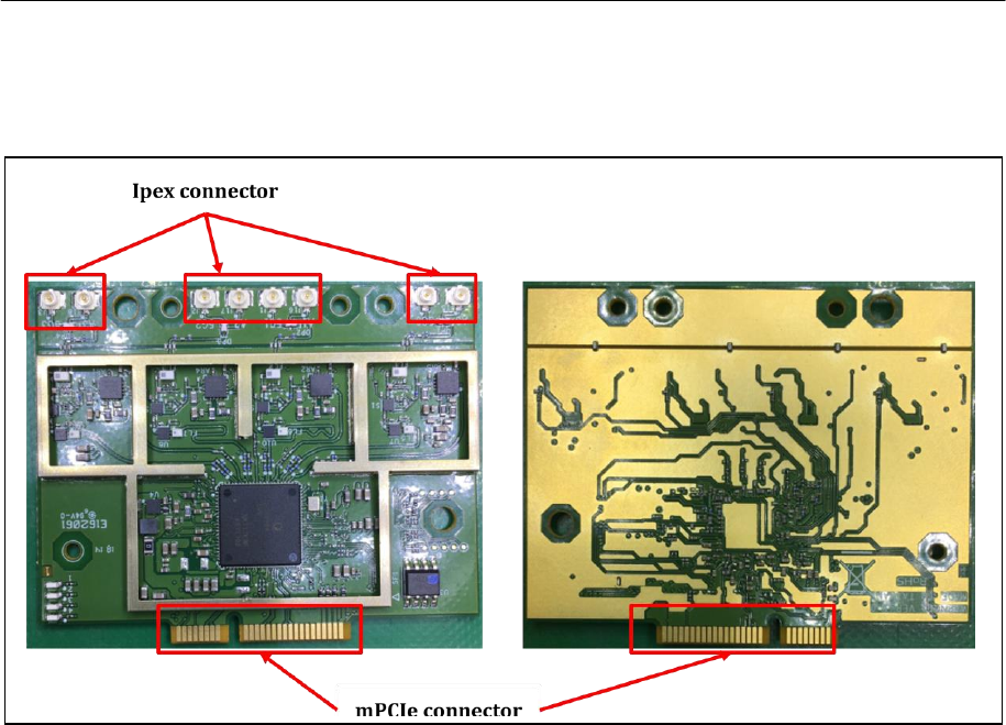
Module Layout
Top and Bottom
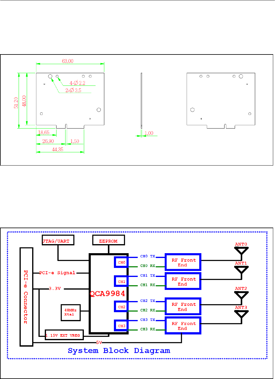
Block Diagram
Below is a block diagram of the WAPN008.
WAPN010 User’s Manual Getting Started
Connector Locations
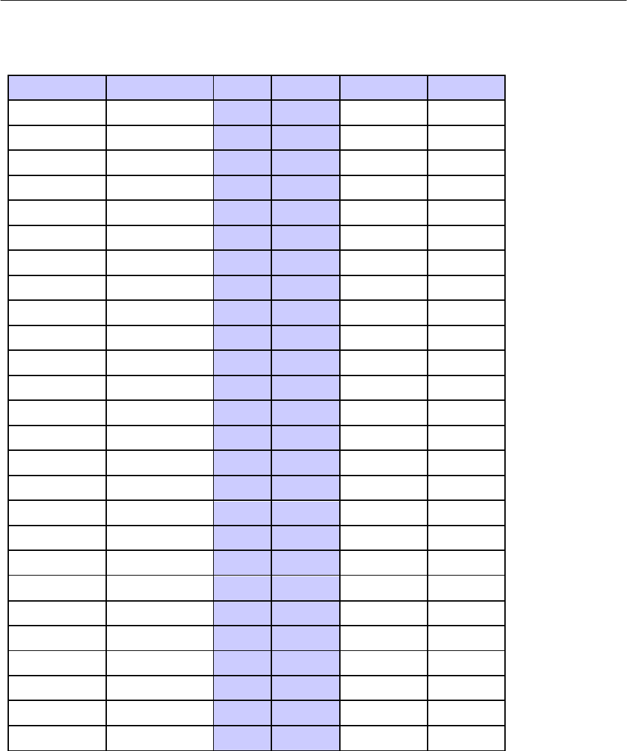
WAPN010 User’s Manual Getting Started
mPCIe Bus Connector PIN Assignments
Function
Connect to
Pin
Pin
Function
Connect to
WAKE_L
WAKE_L
1
2
3.3V
DVDD33
RESERVED
NC
3
4
GND
GND
RESERVED
NC
5
6
1.5V
NC
CLKREQ_L
NC
7
8
UIM_PWR
NC
GND
GND
9
10
UIM_DATA
NC
REFCLK-
REFCLK-
11
12
UIM_CLK
NC
REFCLK+
REFCLK+
13
14
UIM_RESET
NC
GND
GND
15
16
UIM_VPP
NC
UIM_C8
NC
17
18
GND
GND
UIM_C9
NC
19
20
W_DISABLE_L
GPIO18
GND
GND
21
22
RESET_L
RESET_L
PERn0
PERn0
23
24
3.3VAUX
DVDD33
PERp0
PERp0
25
26
GND
GND
GND
GND
27
28
1.5V
NC
GND
GND
29
30
SMB_CLK
NC
PETn0
PETn0
31
32
SMB_DATA
NC
PETp0
PETp0
33
34
GND
GND
GND
GND
35
36
USB_D-
NC
RESERVED
NC
37
38
USB_D+
NC
RESERVED
NC
39
40
GND
GND
RESERVED
NC
41
42
LED_WWAN_L
NC
RESERVED
GND
43
44
LED_WLAN_L
GPIO17
RESERVED
DVDD33
45
46
LED_WPAN_L
NC
RESERVED
DVDD33
47
48
1.5V
NC
RESERVED
DVDD33
49
50
GND
GND
RESERVED
DVDD33
51
52
3.3V
DVDD33

WAPN010 User’s Manual Getting Started
Hardware Installation
The WAPN010 can be installed into all Moxa wireless system board series.
Required Professional Installation Step
1. Install the WAPN010 PCIe card on the system board. Apply pressure to both bus
connectors and gently press the board onto the stack. The board should slide into the
matching bus connectors. Do not attempt to force the board, as this can lead to bent/broken
pins.
2. Screw on the WAPN010 PCIe card.
3. Screw on the all the necessary chassis.
Software Installation
After physically installing the WAPN010, your operating system must be configured to recognize
the new system board.
Required Professional Installation Step
1. Apply power to the system board.
2. Connect system board and PC with Ethernet cable.
3. Open a browser and type: 192.168.127.253 to open the system login webpage.
4. Login the webpage with default password: root in order to verify that all of the hardware is
install properly.

WAPN010 User’s Manual Getting Started
Federal Communication Commission Interference Statement
This equipment has been tested and found to comply with the limits for a Class B digital device, pursuant to
Part 15 of the FCC Rules. These limits are designed to provide reasonable protection against harmful
interference in a residential installation. This equipment generates, uses and can radiate radio frequency
energy and, if not installed and used in accordance with the instructions, may cause harmful interference to
radio communications.
However, there is no guarantee that interference will not occur in a particular installation. If this equipment
does cause harmful interference to radio or television reception, which can be determined by turning the
equipment off and on, the user is encouraged to try to correct the interference by one of the following
measures:
- Reorient or relocate the receiving antenna.
- Increase the separation between the equipment and receiver.
- Connect the equipment into an outlet on a circuit different from that to which the receiver is connected.
- Consult the dealer or an experienced radio/TV technician for help.
FCC Caution:
To assure continued compliance, (example - use only shielded interface cables when connecting to computer or
peripheral devices) any changes or modifications not expressly approved by the party responsible for
compliance could void the user's authority to operate this equipment.
This device complies with Part 15 of the FCC Rules. Operation is subject to the following two conditions:
(1) This device may not cause harmful interference, and
(2) This device must accept any interference received, including interference that may cause undesired
operation.
IMPORTANT NOTE:
This module is restricted to mobile configuration. To comply with FCC RF exposure compliance requirements,
the antenna used for this transmitter must be installed to provide a separation distance of at least 40cm from
all persons and must not be co-located or operating in conjunction with any other antenna or transmitter. This
transmitter module must not be co-located or operating in conjunction with any other antenna or transmitter
CAUTION:
Any changes or modifications not expressly approved by the grantee of this device could void the user's
authority to operate the equipment.
End Product Labeling
This transmitter module is authorized only for use in device where the antenna may be installed such that 40cm
may be maintained between the antenna and users. The final end product must be labeled in a visible area with
the following: "Contains FCC ID: SLE-WAPN010 ”

WAPN010 User’s Manual Getting Started
Canada, Industry Canada (IC) Notices
This device complies with Industry Canada’s licence-exempt RSSs. Operation is subject to the following two
conditions:
(1) This device may not cause interference; and
(2) This device must accept any interference, including interference that may cause undesired operation of the
device.
Canada, avis d'Industry Canada (IC)
Le présent appareil est conforme aux CNR d'Industrie Canada applicables aux appareils radio exempts de
licence. L'exploitation est autorisée aux deux conditions suivantes :
(1) l'appareil ne doit pas produire de brouillage, et
(2) l'utilisateur de l'appareil doit accepter tout brouillage radioélectrique subi, même si le brouillage est
susceptible d'en compromettre le fonctionnement.
Users should also be advised that high-power radars are allocated as primary users (i.e. priority users) of the
bands 5250-5350 MHz and 5650-5850 MHz and that these radars could cause interference and/or damage to
LE-LAN devices.
Devraient également être informés les utilisateurs que les radars à haute puissance sont désignés comme
utilisateurs principaux (c.-à-utilisateurs prioritaires) des bandes 5250-5350 MHz et 5650-5850 MHz et que ces
radars pourraient provoquer des interférences et / ou endommager les appareils LE-LAN.
Radio Frequency (RF) Exposure Information
The radiated output power of the Wireless Device is below the Industry Canada (IC) radio frequency exposure
limits. The Wireless Device should be used in such a manner such that the potential for human contact during
normal operation is minimized.
This device has also been evaluated and shown compliant with the IC RF Exposure limits under mobile exposure
conditions. (antennas are greater than 20cm from a person's body).
Informations concernant l'exposition aux fréquences radio (RF)
La puissance de sortie émise par l’appareil de sans fil est inférieure à la limite d'exposition aux fréquences radio
d'Industry Canada (IC). Utilisez l’appareil de sans fil de façon à minimiser les contacts humains lors du
fonctionnement normal.
Ce périphérique a également été évalué et démontré conforme aux limites d'exposition aux RF d'IC dans des
conditions d'exposition à des appareils mobiles (antennes sont supérieures à 40 cm à partir du corps d'une
personne).
End Product Labeling
This transmitter module is authorized only for use in device where the antenna may be installed such that
40cm may be maintained between the antenna and users. The final end product must be labeled in a visible
area with the following: "Contains IC: 9335A-WAPN010 “
Information for the OEMs and Integrators
The following statement must be included with all versions of this document supplied to an
OEM or integrator, but should not be distributed to the end user.
1) This device is intended for OEM integrators only.
2) Please see the full Grant of Equipment document for other restrictions.
WAPN010 User’s Manual Getting Started
Information for the OEMs and Integrators
The following statement must be included with all versions of this document supplied to an
OEM or integrator, but should not be distributed to the end user.
1) This device is intended for OEM integrators only.
2) Please see the full Grant of Equipment document for other restrictions.
This radio transmitter FCCID: SLE-WAPN010 and IC: 9335A-WAPN010 has been approved by FCC/IC to operate
with the antenna types listed below with the maximum permissible gain and required antenna impedance for
each antenna type indicated. Antenna types not included in this list, having a gain greater than the maximum
gain indicated for that type, are strictly prohibited for use with this device.
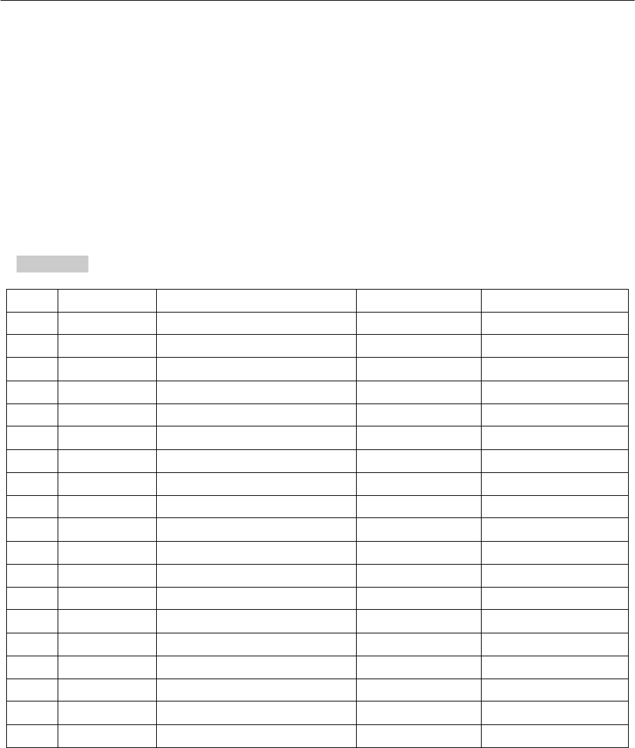
Antenna List
Note: The antenna connector is Reverse SMA type
No.
Manufacturer
Part No.
Antenna Type
Peak Gain
1
MOXA
MAT-WDB-PA-NF-2-0708
Panel
7.63dBi For 2.4GHz
2
MOXA
ANT-WSB-PNF-18
Panel
18dBi For 2.4GHz
3
MOXA
WI25-A1-0810012-RG316
Panel
8.5dBi For 2.4GHz
4
MOXA
ANT-WSB-PNF-12
Panel
12dBi For 2.4GHz
5
MOXA
ANT-WDB-PNF-1518
Panel
15dBi For 2.4GHz
6
MOXA
ANT-WSB-AHRM-05-1.5m BK
Omni-directional
1.51dBi For 2.4GHz
7
MOXA
ANT-WSB-ANF-09
Omni-directional
9dBi For 2.4GHz
8
MOXA
MAT-WDB-CA-RM-2-0205
Omni-directional
2.5dBi For 2.4GHz
9
MOXA
MAT-WDB-DA-RM-2-0203-1m
Omni-directional
2.43dBi For 2.4GHz
10
MOXA
ANT-WDB-ANM-0306
Omni-directional
3.8dBi For 2.4GHz
11
MOXA
ANT-WDB-ARM-0202
Omni-directional
1.8dBi For 2.4GHz
12
MOXA
ANT-WDB-ARM-02
Omni-directional
2.04dBi For 2.4GHz
13
MOXA
ANT-WDB-ANM-0502
Omni-directional
4.62dBi For 2.4GHz
14
MOXA
ANT-WDB-ANM-0407
Omni-directional
4dBi For 2.4GHz
15
MOXA
ANT-WDB-ANF-0609
Omni-directional
6dBi For 2.4GHz
16
MOXA
ANT-WDB-ANM-0609
Omni-directional
6dBi For 2.4GHz
17
MOXA
MHH-A11-XX110170-X0
Railway
9dBi For 2.4GHz
18
MOXA
WI25-A1-1215053-X0
Sector
12dBi For 2.4GHz
19
MOXA
TOP 200 AMR MF-05-4
Patch
8.2dBi For 2.4GHz