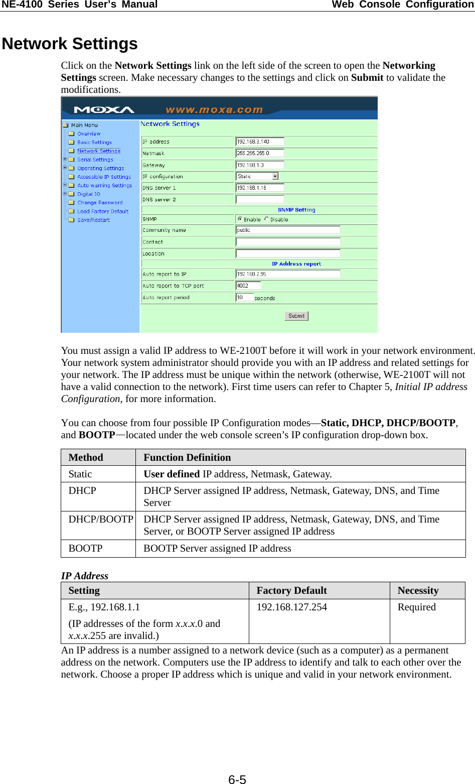
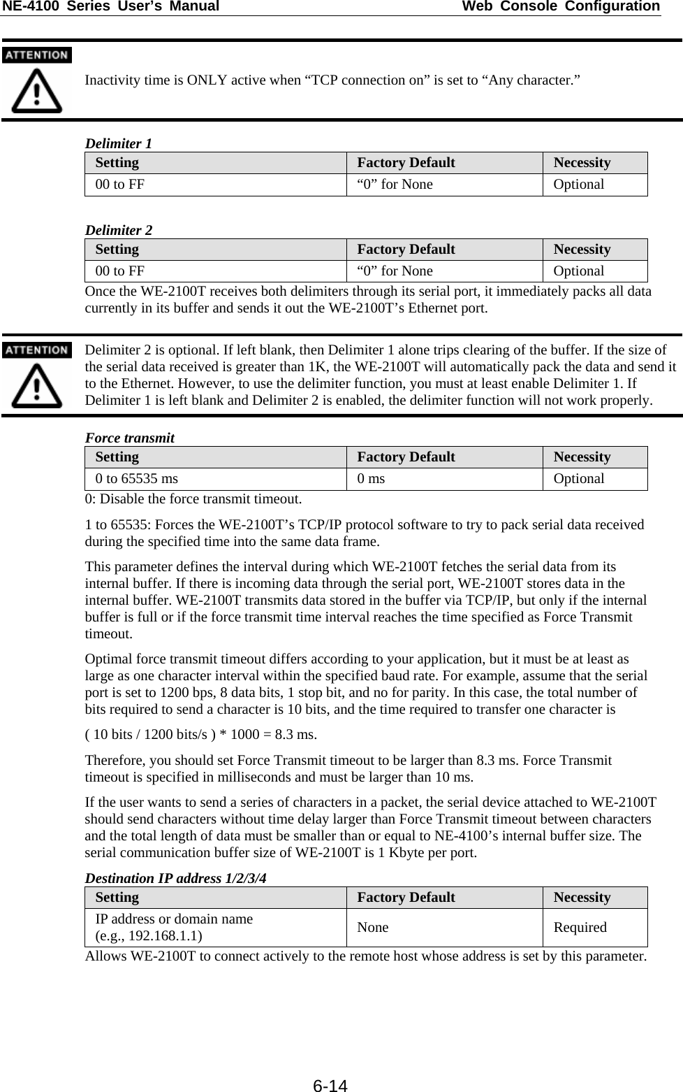
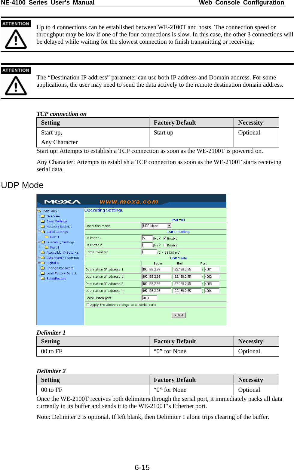
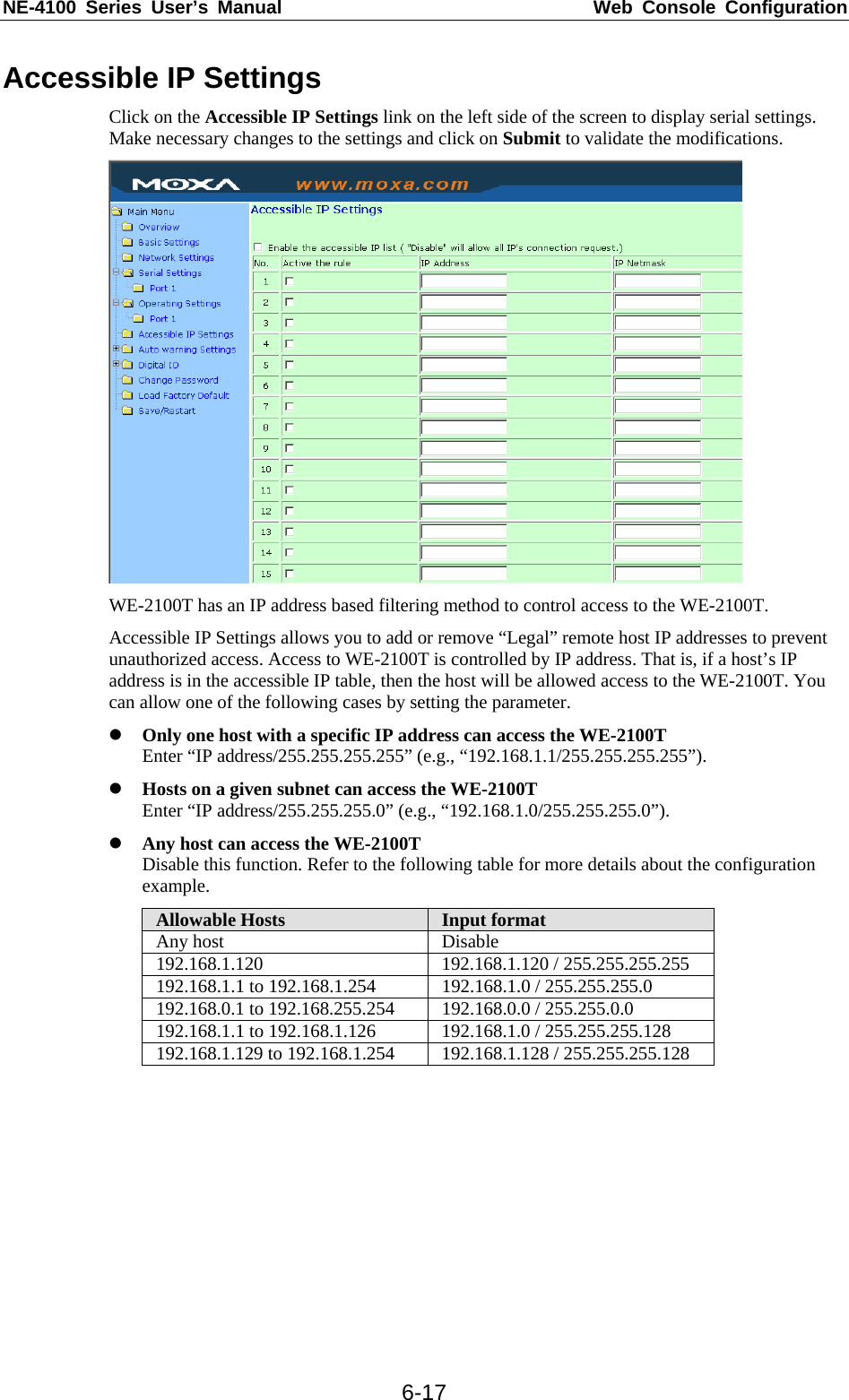
Moxa WE2100T Wireless to Serial Module User Manual NE 4100 Series User s Manual
Moxa Inc. Wireless to Serial Module NE 4100 Series User s Manual
UserManual.wiki
>
Moxa
>
WE2100T User Manual
User manual
Navigation menu
Upload a User Manual
Namespaces
Wiki Guide
HTML
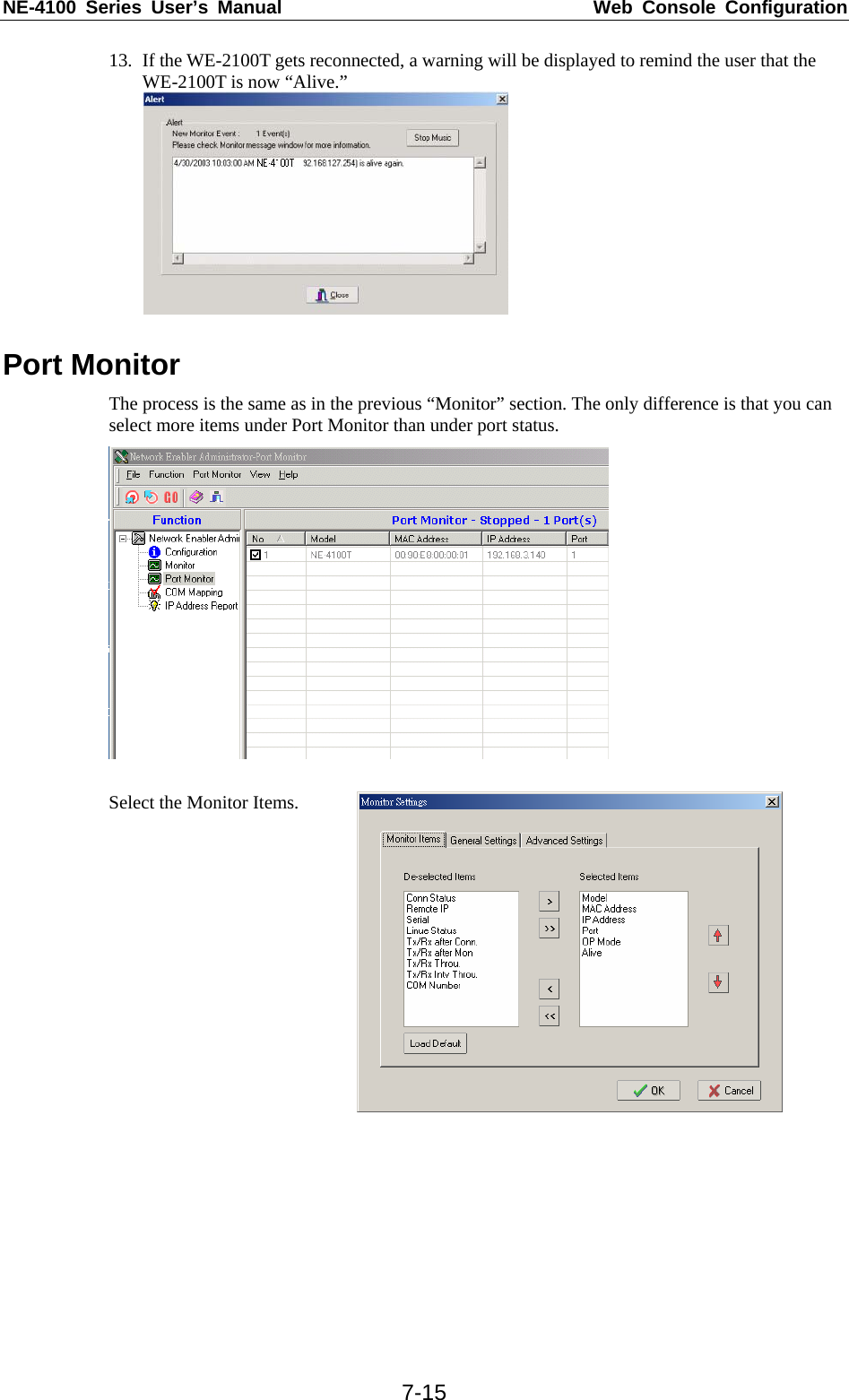
PDF
Info
Views
User Manual
Discussion / Help
Navigation


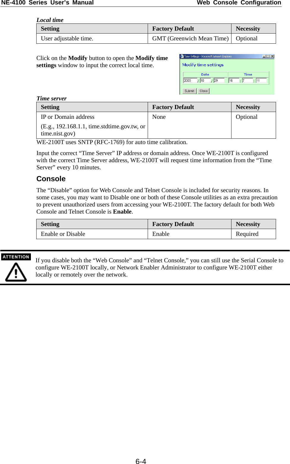
![NE-4100 Series User’s Manual Web Console Configuration 6-3 If you can’t remember the password, the ONLY way to configure the WE-2100T is to load factory defaults by using the Reset button located near the evaluation boards’ DB9 male serial port. Remember to use Network Enabler Administrator to export the configuration file when you have finished the configuration. After using the Reset button to load factory defaults, your configuration can be easily reloaded into WE-2100T by using the Network Enabler Administrator Import function. Refer to Chapter 7 for more details about using the Export and Import functions. Basic Settings Click on the Basic Settings link on the left side of the screen to open the Basic Settings screen. Make necessary changes to the settings and click on submit to validate the modifications. Server name Setting Factory Default Necessity 1 to 39 characters NP[model name]_[Serial No.] Optional This option is useful for specifying the location or application of different WE-2100T. Time WE-2100T has a built-in Real-Time Clock for time calibration functions. Functions such as Auto warning “Email” or “SNMP Trap” can add real-time information to the message. First time users should select the time zone first. The Console will display the “real time” according to the time zone compared to GMT. If you would like to modify the real time clock, select “Local Time.” The WE-2100T’s firmware will modify the GMT time according to the Time Zone. Time zone Setting Factory Default Necessity User selectable time zone GMT (Greenwich Mean Time) Optional](https://usermanual.wiki/Moxa/WE2100T/User-Guide-819430-Page-31.png)

![NE-4100 Series User’s Manual Web Console Configuration 6-18Auto Warning Settings Click on the Auto Warning Settings link on the left side of the screen to display serial settings. Make necessary changes to the settings and click on Submit to validate the modifications. E-mail and SNMP Trap Mail server Mail server Setting Factory Default Necessity IP or Domain Name None Optional User name Setting Factory Default Necessity 1 to 15 characters None Optional Password Setting Factory Default Necessity 1 to 15 characters None Optional From E-mail address Setting Factory Default Necessity 1 to 63 characters NE_[Serial No.]@[WE-2100T Series Module Name] Optional E-mail address 1/2/3/4 Setting Factory Default Necessity 1 to 63 characters None Optional Consult your network administrator or ISP for the proper mail server settings. The Auto warning function may not work properly if not set up properly. WE-2100T SMTP AUTH supports LOGIN, PLAIN, CRAM-MD5 (RFC 2554). SNMP trap server SNMP trap server IP or domain name Setting Factory Default Necessity IP or Domain Name None Optional](https://usermanual.wiki/Moxa/WE2100T/User-Guide-819430-Page-46.png)


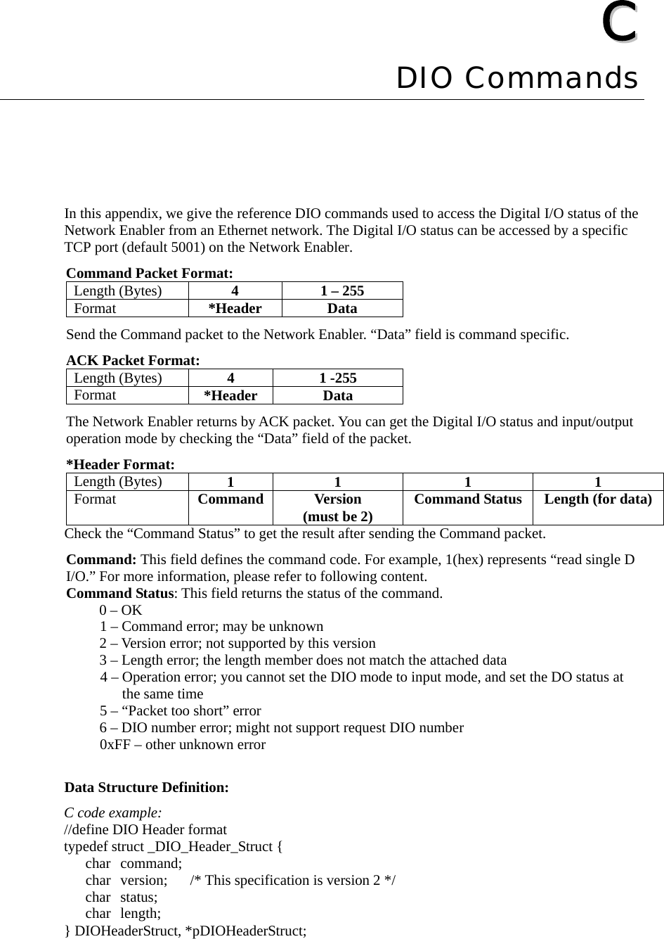
![NE-4100 Series User’s Manual DIO Commands C-2//define DIO Packet format //Used for Command and ACK packet typedef struct _DIO_Packet_Struct { DIOHeaderStruct header; char data[255]; } DIOPacketStruct, *pDIOPacketStruct; Command Code Usage 1. Reading Single DIO Parameters: Command code: 1(hex) Version: 2(hex) Command Status: doesn’t matter Length of data: 1(hex), represents one byte. data[0]: Fill in the number of the DIO you wish to access. The DIO number starts from 0(hex). Return: Command Status: Check the Command Status code on the previous page. Length of data: 3(hex). Must be 3 bytes of return code in this mode. data[0]: The number of the DIO you wish to access. data[1]: DIO mode(hex), 0 for IN, 1 for OUT data[2]: DIO status(hex), 0 for LOW, 1 for HIGH C code example: BOOL ReadSingleDIO(int port, int *mode, int *status) { DIOPacketStruct packet; packet.header.command = 1; // read single DIO command packet.header.version = 2; // DIO protocol version packet.header.length = 1; // data length packet.data[0] = (char)port; // Number of the DIO send(SocketFd, (char *)&packet, sizeof(DIOHeaderStruct)+1, 0); //Send TCP Packet // Process the returned data here. return TRUE; } 2. Writing a Single DIO Parameters: Command code: 2(hex) Version: 2(hex) Command Status: doesn’t matter Length of data: 3(hex); represents three bytes. data[0]: The number of the DIO you wish to access. data[1]: DIO mode(hex), 0 for IN, 1 for OUT data[2]: DIO status(hex), 0 for LOW, 1 for HIGH Return: Command Status: Check the Command Status code on the previous page. Length of data: 3(hex). Must be 3 bytes of return code in this mode. data[0]: The number of the DIO you wish to access. data[1]: DIO mode(hex), 0 for IN, 1 for OUT data[2]: DIO status(hex), 0 for LOW, 1 for HIGH](https://usermanual.wiki/Moxa/WE2100T/User-Guide-819430-Page-75.png)
![NE-4100 Series User’s Manual DIO Commands C-3C code example: void WriteSingleDIO(int port, int mode, int status) { DIOPacketStruct packet; packet.header.command = 2; // write single DIO command packet.header.version = 2; // DIO protocol version packet.header.length = 3; // data length packet.data[0] = (char)port; // number of the DIO packet.data[1] = (char)mode; // DIO mode packet.data[2] = (char)status; // DIO status; send(SocketFd, (char *)&packet, sizeof(DIOHeaderStruct)+3, 0); //Send TCP packet //Process the returned data here } 3. Reading Multiple DIOs Parameter: Command code: 5(hex) Version: 2(hex) Command status: doesn’t matter Length of data: 2(hex); represents two bytes. data[0]: Number of the DIO you wish to access first. data[1]: The last number of the DIO you wish to access. Return: Command Status : Check the Command Status code on the previous page. Length of data: (end-start+1)*2 data[0]: mode of start DIO data[1]: status of start DIO data[2]: mode of (start+1) DIO data[3]: status of (start+1) DIO …. data[(end-start)*2]: mode of end DIO data[(end-start)*2+1]: status of end DIO C code example: BOOL ReadMultipleDIO(int start, int end, int *mode, int *status) { DIOPacketStruct packet; packet.header.command = 5; // Read Multiple DIO Commands packet.header.version = 2; // DIO protocol command version packet.header.length = 2; // data length packet.data[0] = start; // start of the DIO number packet.data[1] = end; // end of the DIO number send(SocketFd, (char *)&packet, sizeof(DIOHeaderStruct)+2, 0); //Send TCP packet //Process the returned data here return TRUE; }](https://usermanual.wiki/Moxa/WE2100T/User-Guide-819430-Page-76.png)
![NE-4100 Series User’s Manual DIO Commands C-44. Writing Multiple DIOs Parameters: Command code: 6(hex) Version: 2(hex) Command status: doesn’t matter Length of data: (end-start+1)*2 + 2 data[0]: Number of the DIO you wish to access first. data[1]: The last number of the DIO you wish to access data[2]: mode of start DIO data[3]: status of start DIO data[4]: mode of (start+1) DIO data[5]: status of (start+1) DIO …. data[(end-start)*2+2]: mode of end DIO data[(end-start)*2+3]: status of end DIO Return: Command Status: Check the Command Status code on the previous page. Length of data : (end-start+1)*2 data[0]: mode of start DIO data[1]: status of start DIO data[2]: mode of (start+1) DIO data[3]: status of (start+1) DIO …. data[(end-start)*2]: mode of end DIO data[(end-start)*2+1]: status of end DIO C code example: void WriteMultipleDIO(int start, int end, int* mode, int* status) { DIOPacketStruct packet; packet.header.command = 6; // Write Multiple DIO Command Codes packet.header.version = 2; // DIO protocol version packet.header.length = (end-start+1)*2+2; // data length packet.data[0] = start; // start DIO number packet.data[1] = end; // end DIO number int i, len; for ( i=0; i<(end-start+1);i++ ) { packet.data[i+2] = mode[i]; packet.data[i+3] = status[i]; } send(SocketFd, )(char*)&packet,( end-start+1)*2+2+sizeof(DIOHeaderStruct), 0); //Send TCP packet //Process the returned data here } Note: A utility that can be used to test the DIO access commands can be found on the CD-ROM.](https://usermanual.wiki/Moxa/WE2100T/User-Guide-819430-Page-77.png)