Moxa WFS001 Industrial 900MHz Access Point Confirmed User Manual
Moxa Inc. Industrial 900MHz Access Point Confirmed
Moxa >
User manual

Moxa900MHzPCIModule
WFS001User’sManual
www.moxa.com
FirstEdition,July2014
2014MoxaInc.Allrightsreserved.
Reproductionwithoutpermissionisprohibited.

WFS001User’sManual
Thehardwareandsoftwaredescribedinthismanualisfurnishedunderalicenseagreementandmaybeused
onlyinaccordancewiththetermsofthatagreement.
CopyrightNotice
Copyright2014MoxaInc.
Allrightsreserved.
Reproductionwithoutpermissionisprohibited.
Trademarks
MOXAisaregisteredtrademarkofMoxaInc.
Allothertrademarksorregisteredmarksinthismanualbelongtotheirrespectivemanufacturers.
Disclaimer
Informationinthisdocumentissubjecttochangewithoutnoticeanddoesnotrepresentacommitmentonthe
partofMoxa.
Moxaprovidesthisdocument“asis,”withoutwarrantyofanykind,eitherexpressedorimplied,including,but
notlimitedto,itsparticularpurpose.Moxareservestherighttomakeimprovementsand/orchangestothis
manual,ortotheproductsand/ortheprogramsdescribedinthismanual,atanytime.
Informationprovidedinthismanualisintendedtobeaccurateandreliable.However,Moxaassumesno
responsibilityforitsuse,orforanyinfringementsontherightsofthirdpartiesthatmayresultfromitsuse.
Thisproductmightincludeunintentionaltechnicalortypographicalerrors.Changesareperiodicallymadeto
theinformationhereintocorrectsucherrors,andthesechangesareincorporatedintoneweditionsofthe
publication.
TechnicalSupportContactInformation
www.moxa.com/support
MoxaAmericas:
Toll‐free:1‐888‐669‐2872
Tel:+1‐714‐528‐6777
Fax:+1‐714‐528‐6778

MoxaEurope:
Tel:+49‐89‐3700399‐0
Fax:+49‐89‐3700399‐99
TableofContents
Chapter1Introduction
Overview
Features
Specification
Chapter2GettingStarted
ModuleLayout
BlockDiagram
HardwareInstallation
SoftwareInstallation

WFS001 User’s Manual Introduction
1
1
Chapter 1 Introduction
Thefollowingtopicsarecoveredinthischapter:
OverviewFeatures
Specifications

WFS001 User’s Manual Introduction
Overview
WFS001PCIModuleisdesignedtoprovidewirelesscommunicationforallwirelessdevicebasedsystems.It
communicatesviathestandard802.11b/gprotocolsbutwithtransmissionfrequencyshiftedto900MHz
(902‐928MHz).TheWFS001usestheAR5414wirelesschipsetfromAtheros.Thismoduleisconnectedtothe
PCIbusthroughaPCIconnectorandspecialcircuitrytoallowforcompatibilitywitheither3.3Vor5VPCI
signaling..
Features
All‐CMOSsinglechipforIEEE802.11b/gcompatibleWLANsin900MHz
Basebandin‐phase(I)andquadrature(Q)signals,convertsthemtothedesiredfrequency,anddrivesthe
RFsignaloff‐chip.
Integratedlow‐noiseamplifier(LNA)
ExternalPAand/orLNAcanbeusedforspecialapplications
Advancedwidebandreceiverwithbestpathsequencerforbetterrangeandmultipathresistancethan
conventionalequalizer‐baseddesigns
HighspeedUARTwithDMAsupportsdataratesupto1Mbps
Specification
FeaturesWFS001
ChipsetAtherosAR5414
BasebandProcessor
(BBP)
- BPSK,QPSK,16QAM,64QAM,DBPSK,
DQPSK,andCCKmodulationschemes
- Dataratesof6–54Mbpsfor802.11a,1–54
Mbpsfor802.11g,1–11Mbpsfor802.11b,
AtherosSuperA/Gmodewithupto108
Mbps
securityengineWEP64,WEP128,WEP256,AES‐CCM,TKIP,WPS
BusInterfacePCI2.3complaint
ConnectorsDefinedBTBconnectorisusing2x40pinsheader,andSupportPCIExpressstandard.
Powerrequirement1.2V+/‐5%
1.8V+/‐5%
3.3V+/‐10%
Dimension50mmx49mmx1.2mm
Weight15g
Operating
Temperature
‐40to+80℃
Storage
Temperature:
‐40to+150℃
Operatesin2.4and
5GHzfrequency
bands.
2.4GHz2.312–2.472GHz,2.484GHz
5GHzU‐NII5.15–5.35GHz,5.725–5.825GHz
ISM5.725–5.850GHz
DSRC5.850–5.925GHz
Europe5.15–5.35GHz,5.47–5.725GHz
Japan4.90–5.00GHz,5.03–5.091GHz,
5.15–5.25GHz

2
2
Chapter 2 GettingStarted
Thischaptercoversthemodulelayout,andblockdiagram,hardwareinstallationoftheWFS001.Software
installationiscoveredinthenextchapter.
Thefollowingtopicsarecovered:
ModuleLayout
BlockDiagram
HardwareInstallation
SoftwareInstallation
WFS001 User’s Manual Getting Started
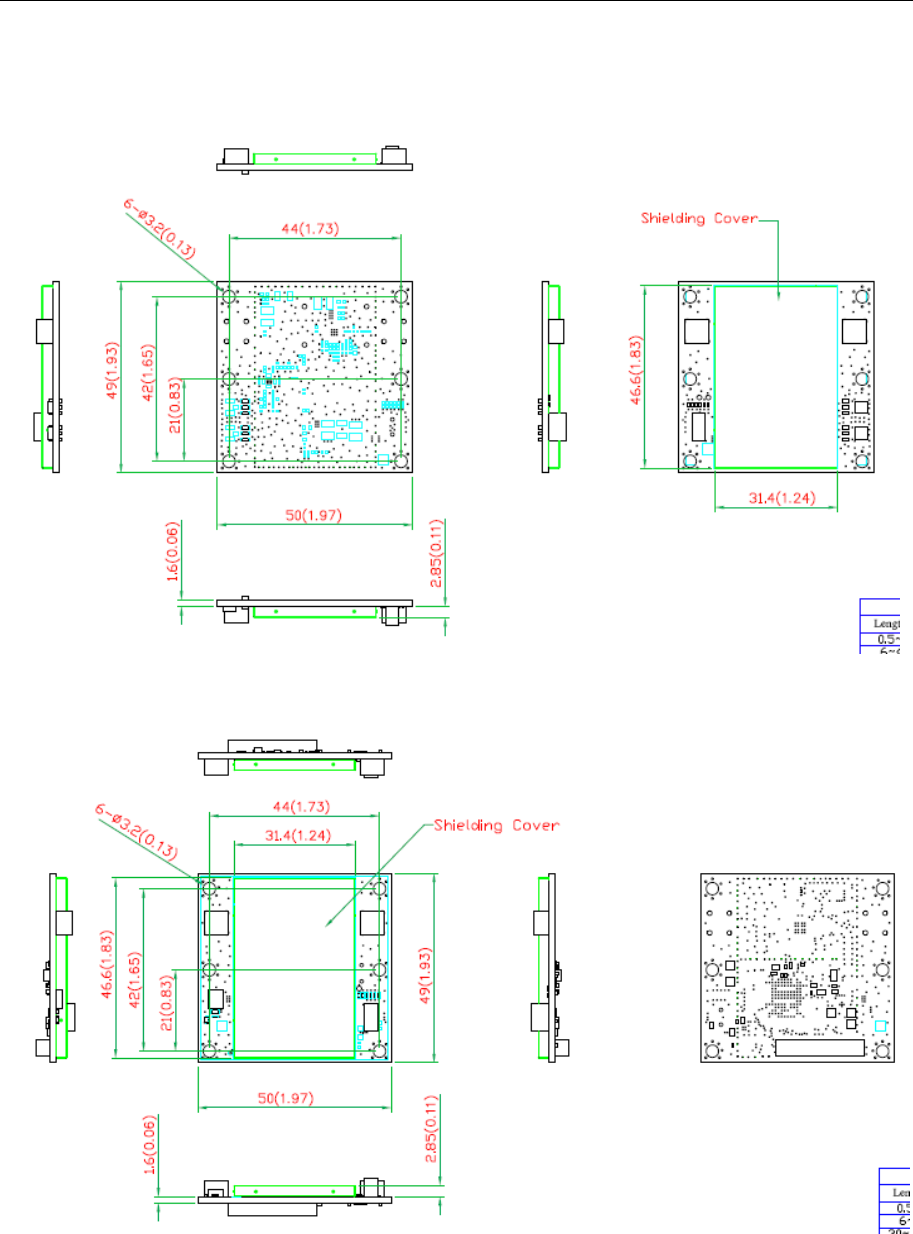
ModuleLayout
Top
Bottom
WFS001 User’s Manual Getting Started
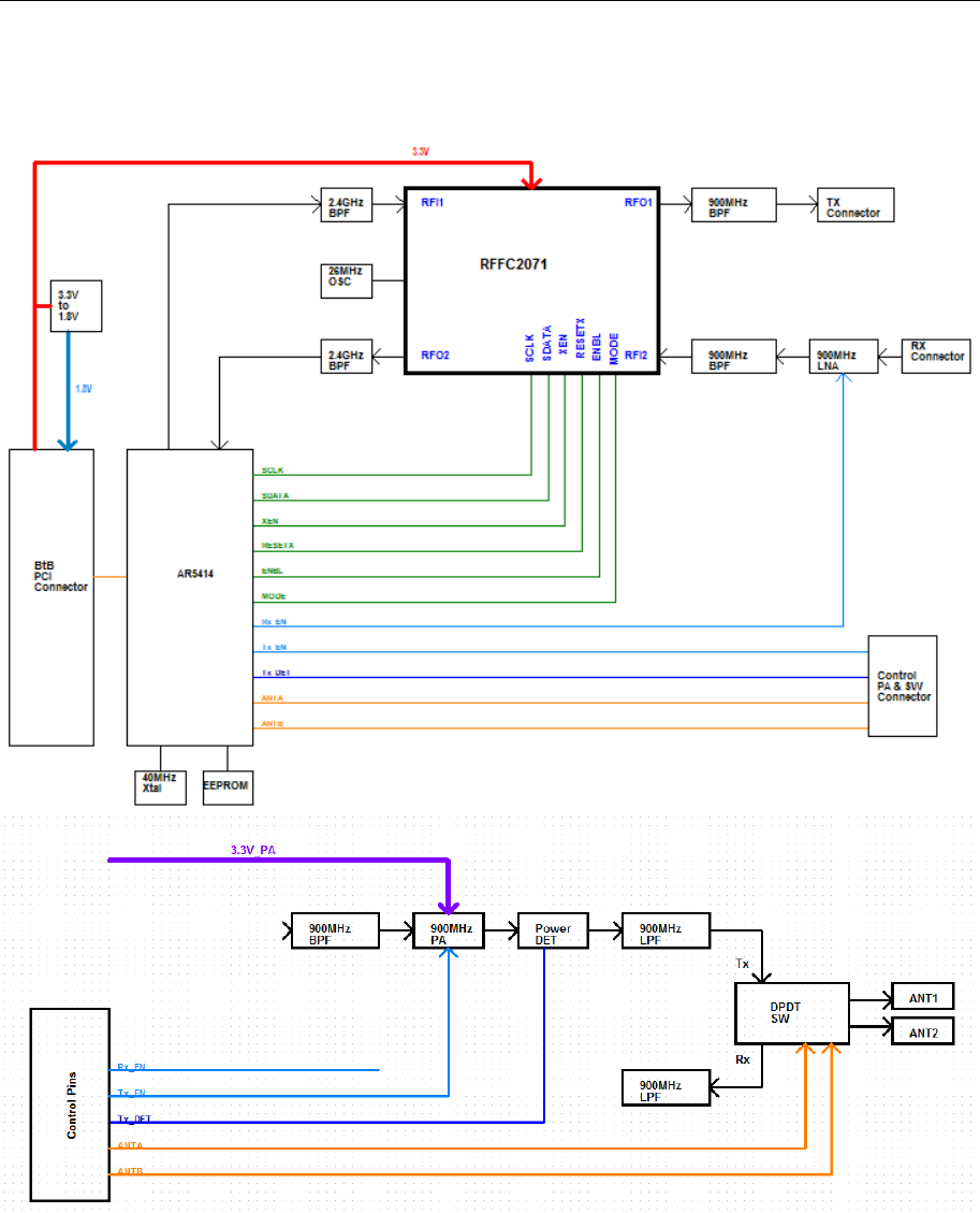
BlockDiagram
BelowisablockdiagramoftheWFS001.
WFS001 User’s Manual Getting Started
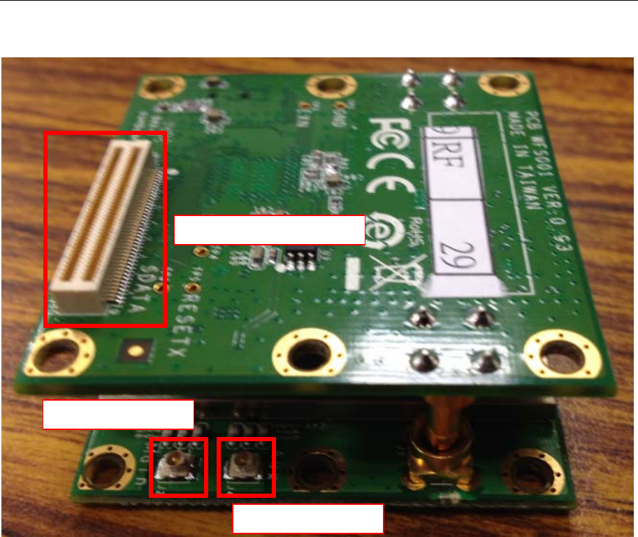
ConnectorLocations
BoardtoBoardConnector
RFMainConnector
RFAUXConnector
WFS001 User’s Manual Getting Started
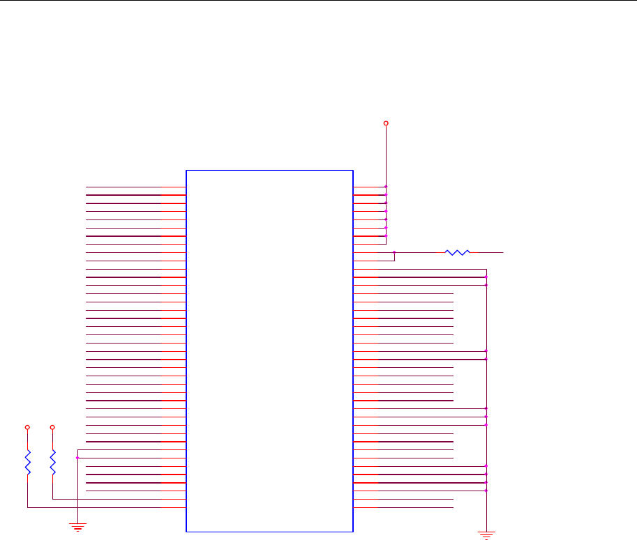
PCIBusConnectorPINAssignments
AD30
3.3V_CON
PCI_INT_L
PCI_GNT_L
AD31
PCI_CBE2_L
AD1
PCI_CBE3_L
AD3
PCI_PME_L
PCI_CBE1_L
AD5
PCI_RST_L
AD7
AD0
AD8
MPCI_12
MPCI_11
AD4
AD10
AD2
RF_DISABLE
AD6
PCI_CLK
PCI_REQ_L
AD9
AD12
PCI_CBE0_L
AD14
AD13
AD11
PCI_PERR_L
PCI_DEVSEL_L
AD15
PCI_SERR_L
AD17
R9
R0603
187
GPIO_5
AD19
3.3V
AD21
PCI_TRDY_L
PCI_STOP_L
PCI_IRDY_LAD23
AD16 PCI_CLKRUN_L
PCI_FRAME_L
R8
R0603
187
3.3V
AD18
J1
DEFINE BOARD EDGE
3.3V-3 6
INTA# 34
GND-7 72
3.3VAUX 18
CLK 30
RST# 28
GND-5 60
3.3V-4 8
REQ# 36
GNT# 38
3.3V-6 12
GND-11 22
AD31
63
PME# 68
AD29
59
GND-13 26
AD30
61
AD27
55
3.3V-5 10
AD25
51
AD28
57
AD26
53
CBE3#
75
AD24
49 AD23
47
IDSEL 66
GND-4 58
GND-15 44
AD21
43
AD22
45
AD19
39
AD20
41
GND-3 56
PAR 46
AD17
35
AD18
37
CBE2#
73
AD16
33
IRDY# 48
GND-12 24
3.3V 2
FRAME# 52
CLKRUN# 32
TRDY # 50
SERR# 62
STOP# 54
GND-8 74
3.3V-7 14
PERR# 40
DEVSEL# 64
CBE1#
71
GND-14 42
AD14
29
AD15
31
AD13
27 AD12
25 AD11
23 AD10
21
GND-9 76
AD9
19 AD8
17
CBE0#
69
AD7
15 3.3V-8 16
3.3V-2 4
AD6
13 AD5
11 AD4
9
AD2
5
AD3
7
AD0
1
AD1
3
GND-6 70
LED1-GRNN 78
GND-1
67 GND
65
3.3VAUX-1 20
LED1-GRNP
77
LED2-YELP
79 LED2-Y ELN 80
PCI_PAR
AD25
3.3V_AUX
AD27
AD22
AD20
AD29
AD24
MPCI_14
PCI_IDSEL_L
AD28
AD26
R26
R0402
R

WFS001 User’s Manual Getting Started
HardwareInstallation
TheWFS001canbeinstalledintoallMoxawirelesssystemboardseries.
StepforInstallation
1.AttachtheWLANantennatoconnectorJ1.
2.Ifusing2ndWLANantenna,attachittoconnectorJ2.
3.InstalltheWFS001PCIcardonthesystemboard.Applypressuretobothbus
connectorsandgentlypresstheboardontothestack.Theboardshouldslideintothe
matchingbusconnectors.Donotattempttoforcetheboard,asthiscanleadtobent/broken
pins.
4.ScrewontheWFS001PCIcard.
5.IfanypowerboardsaretobestackedabovetheWFS001,installthem.
6.Screwontheallthenecessarychassis.
SoftwareInstallation
AfterphysicallyinstallingtheWFS001,youroperatingsystemmustbeconfiguredtorecognize
thenewsystemboard.
StepforInstallation
1.Applypowertothesystemboard.
2.ConnectsystemboardandPCwithEthernetcable.
3.Openabrowserandtype:192.168.127.253toopenthesystemloginwebpage.
4.Loginthewebpagewithdefaultpassword:rootinordertoverifythatallofthehardwareis
installproperly.

WFS001 User’s Manual Getting Started
FederalCommunicationCommissionInterferenceStatement
ThisequipmenthasbeentestedandfoundtocomplywiththelimitsforaClassBdigitaldevice,pursuantto
Part15oftheFCCRules.Theselimitsaredesignedtoprovidereasonableprotectionagainstharmful
interferenceinaresidentialinstallation.Thisequipmentgenerates,usesandcanradiateradiofrequency
energyand,ifnotinstalledandusedinaccordancewiththeinstructions,maycauseharmfulinterferenceto
radiocommunications.
However,thereisnoguaranteethatinterferencewillnotoccurinaparticularinstallation.Ifthisequipment
doescauseharmfulinterferencetoradioortelevisionreception,whichcanbedeterminedbyturningthe
equipmentoffandon,theuserisencouragedtotrytocorrecttheinterferencebyoneofthefollowing
measures:
‐Reorientorrelocatethereceivingantenna.
‐Increasetheseparationbetweentheequipmentandreceiver.
‐Connecttheequipmentintoanoutletonacircuitdifferentfromthattowhichthereceiverisconnected.
‐Consultthedealeroranexperiencedradio/TVtechnicianforhelp.
FCCCaution:
Toassurecontinuedcompliance,(example‐useonlyshieldedinterfacecableswhenconnectingtocomputeror
peripheraldevices)anychangesormodificationsnotexpresslyapprovedbythepartyresponsiblefor
compliancecouldvoidtheuser'sauthoritytooperatethisequipment.
ThisdevicecomplieswithPart15oftheFCCRules.Operationissubjecttothefollowingtwoconditions:
(1)Thisdevicemaynotcauseharmfulinterference,and
(2)Thisdevicemustacceptanyinterferencereceived,includinginterferencethatmaycauseundesired
operation.
IMPORTANTNOTE:
Thismoduleisrestrictedtomobileconfiguration.TocomplywithFCCRFexposurecompliancerequirements,
theantennausedforthistransmittermustbeinstalledtoprovideaseparationdistanceofatleast20cmfrom
allpersonsandmustnotbeco‐locatedoroperatinginconjunctionwithanyotherantennaortransmitter.This
transmittermodulemustnotbeco‐locatedoroperatinginconjunctionwithanyotherantennaortransmitter
CAUTION:
Anychangesormodificationsnotexpresslyapprovedbythegranteeofthisdevicecouldvoidtheuser's
authoritytooperatetheequipment.

WFS001 User’s Manual Getting Started
EndProductLabeling
Thistransmittermoduleisauthorizedonlyforuseindevicewheretheantennamaybeinstalledsuchthat20cm
maybemaintainedbetweentheantennaandusers.Thefinalendproductmustbelabeledinavisibleareawith
thefollowing:"ContainsFCCID:SLE‐WFS001”
InformationfortheOEMsandIntegrators
Thefollowingstatementmustbeincludedwithallversionsofthisdocumentsuppliedtoan
OEMorintegrator,butshouldnotbedistributedtotheenduser.
1)ThisdeviceisintendedforOEMintegratorsonly.
2)PleaseseethefullGrantofEquipmentdocumentforotherrestrictions.
ThisradiotransmitterFCCID:SLE‐WFS001hasbeenapprovedbyFCCtooperatewiththeantennatypeslisted
belowwiththemaximumpermissiblegainandrequiredantennaimpedanceforeachantennatypeindicated.
Antennatypesnotincludedinthislist,havingagaingreaterthanthemaximumgainindicatedforthattype,are
strictlyprohibitedforusewiththisdevice.
AntennaList
No.ManufacturerPartNo.AntennaTypePeakGain
1WanshihQJ1MPA0003ADipoleAntenna2.37dBi
Note:TheantennaconnectorisReverseSMAtype.