Moxa ZB-DCU3-T Sub-1G communication module User Manual Sub 1G
Moxa Inc. Sub-1G communication module Sub 1G
Moxa >
User Manual_rev.pdf

Moxa Industrial Sub-1G Module
ZB-DCU3-T, ZB-PM3-T, ZB-WAN1-T
User’s Manual
First Edition, August 2014
www.moxa.com/product
© 2014 Moxa Inc. All rights reserved.
Reproduction without permission is prohibited.
Moxa Industrial Sub-1G Module
ZB-DCU3-T, ZB-PM3-T, ZB-WAN1-T
User’s Manual
The software described in this manual is furnished under a license agreement and may be used only in accordance with
the terms of that agreement.
Copyright Notice
© 2014 Moxa Inc. All rights reserved.
Trademarks
The MOXA logo is a registered trademark of Moxa Inc.
All other trademarks or registered marks in this manual belong to their respective manufacturers.
Disclaimer
Information in this document is subject to change without notice and does not represent a commitment on the part of
Moxa.
Moxa provides this document as is, without warranty of any kind, either expressed or implied, including, but not limited
to, its particular purpose. Moxa reserves the right to make improvements and/or changes to this manual, or to the
products and/or the programs described in this manual, at any time.
Information provided in this manual is intended to be accurate and reliable. However, Moxa assumes no responsibility
for
its use, or for any infringements on the rights of third parties that may result from its use.
This product might include unintentional technical or typographical errors. Changes are periodically made to the
information herein to correct such errors, and these changes are incorporated into new editions of the publication.
Technical Support Contact Information
www.moxa.com/support
Moxa Americas Moxa China (Shanghai office)
Toll-free: 1-888-669-2872 Toll-free: 800-820-5036
Tel: +1-714-528-6777 Tel: +86-21-5258-9955
Fax: +1-714-528-6778 Fax: +86-21-5258-5505
Moxa Europe Moxa Asia-Pacific
Tel: +49-89-3 70 03 99-0 Tel: +886-2-8919-1230
Fax: +49-89-3 70 03 99-99 Fax: +886-2-8919-1231
Table of Contents
1. Introduction ........................................................................................................ 1-1
Overview .................................................................................... 1-2
Features ..................................................................................... 1-2
Specifications ............................................................................ 1-2
2. Getting Started .............................................................................................. 2-1
Module Layout ............................................................................ 2-2
Block Diagram ............................................................ 2-2
Connector Locations ................................................................. 2-3
Hardware Installation ............................................................. 2-3
Software Installation ........................................................... 2-3
A. Regulatory Statements............................................................................. A-1

1
1.
Introduction
The following topics are covered in this chapter:
Overview
Features
Specifications

Overview
Moxa Sub-1G module(ZB-DCU3-T, ZB-PM3-T, ZB-WAN1-T) uses ATMEL
wireless microcontroller which provides a comprehensive solution with large
memory(256KB Flash and 16KB SRAM), high CPU and radio performance and all
RF components included.
The module is a range of ultra low power, high performance surface mount
modules targeted at Sub-1G networking applications, enabling users to realize
products with minimum time to market and at the lowest cost. Sub-1G
module(ZB-DCU3-T, ZB-PM3-T, ZB-WAN1-T) can implement networking stacks,
such as ZigBee, as well as customer applications
Note:
* The Sub-1G module will implement into Moxa System’s DCU and CFE/Protecsa’s
Smart Meter application. So, it should follow Moxa System’s DCU-8620-T specification
and CFE/Protecsa AMI specification that provided by CFE company.
Features
• Support SCM setting
• Support upgrade firmware over the AIR
• Support AES-128 compatible encryption
• Support large packets fragmentation
• Support Mesh topology
Specifications
Sub-1G Interface
Internal Memory: 256KB
Flash : 256KB. SRAM: 16KB
RF Standard: IEEE 802.15.4
Frequency Band: 769 ~ 935 MHz
RF Data Rate: 20 ~ 40 Kbps (BPSK modulation)
RF Channel: 10 channel
Tx Power: +10 dBm
Rx sensitivity: -110 dBm
Distance: 900M
Serial Communication Parameters
UART Baud Rate: 50 bps to 115.2K Kbps
Power Requirement
Power consumption: RX:26 mA TX:110 mA
Operating Supply Voltage: 3.3 V

Environmental Limits
Operating Temperature: -40 to 75°C (-40 to 167°F)
Operating Humidity: 5 to 95% RH
Storage Temperature: -40 to 85°C (-40 to 185°F)
Physical Characteristics
Dimension: ZB-DCU3-T/ZB-WAN1-T (48x30x1.6mm), ZB-PM3-T (45x38x1.6mm)
Standard and Certifications
EMC: CE (EN55022 and EN55024 Class A), FCC Part 15 Subpart B Class A
Reliability
Automatic Reboot Trigger: Built-in WDT (watchdog timer)
MTBF (meantime between failures): Over 10 years
Warranty
Warranty Period: 5 years
Details: See www.moxa.com/warranty

2
2.
Getting Started
This chapter covers the module layout, and block diagram, hardware installation
of the Sub-1G module. Software installation is covered in the next chapter.
Module Layout
Block Diagram
Connector Locations
Hardware Installation
Software Installation
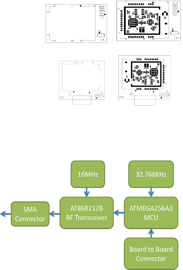
Module Layout
ZB-DCU3-T, ZB-WAN1-T
+
ZB-PM3-T
+
Block Diagram
=
=
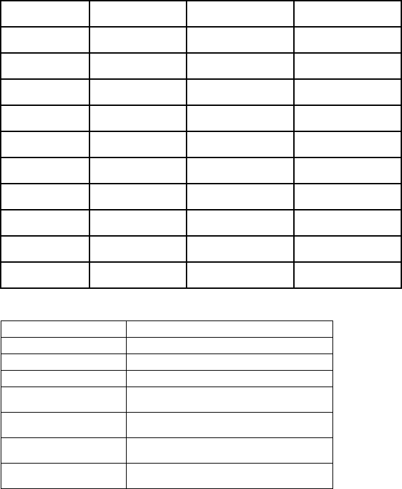
PIN Define
ZB-DCU3-T, ZB-WAN1-T
PIN Number
PIN Function
PIN Number
PIN Function
1 3.3V 2 3.3V
3 GND 4 GND
5 GND 6 GND
7 NC 8 NC
9 NC 10 NC
11 RXD 12 NC
13 TXD 14 NC
15 NC 16 NC
17 NC 18 NC
19 NC 20 RESET
ZB-PM3-T
PIN Number
PIN Function
1 VCC
2 TXD
3 RXD
4
RST
5
NC
6
GND
7
GND
Hardware Installation
The Sub-1G Module can be installed into Moxa DCU-8620-T Embedded
Computer system and Power Meter.
Steps for Installation on DCU
1. Attach the WLAN antenna to connector UI.
2. Let Sub-1G Module(ZB-DCU3-T and ZB-WAN1-T) connect to DCU-8620-T.
3. Screw on the Sub-1G Module
Steps for Installation on Power Meter
1. Let Sub-1G Module(ZB-PM3-T) connect to Power Meter.
2. Recover the Power Meter.
Software Installation
After physically installing the Sub-1G module, the module will be recognized on
the new system board after the following steps.
Steps for Installation
1. Apply power to the system board.
2. Run DCU-8620-T application program. Make sure it could communicate with
Sub-1G module(ZB-WAN1-T and ZB-DCU3-T).
3. Apply power to the Power Meter. Make sure the LED of “Ready” light-on on
Power Meter.
4. Run DCU-8620-T application program, make sure it could read data from
Power Meter through the air.

A
A.
Regulatory Statements
Federal Communication Commission Interference Statement
This device complies with Part 15 of the FCC Rules. Operation is subject to the following
two conditions: (1) This device may not cause harmful interference, and (2) this device
must accept any interference received, including interference that may cause undesired
operation.
This equipment has been tested and found to comply with the limits for a Class B digital
device, pursuant to Part 15 of the FCC Rules. These limits are designed to provide
reasonable protection against harmful interference in a residential installation. This
equipment generates, uses and can radiate radio frequency energy and, if not installed
and used in accordance with the instructions, may cause harmful interference to radio
communications. However, there is no guarantee that interference will not occur in a
particular installation. If this equipment does cause harmful interference to radio or
television reception, which can be determined by turning the equipment off and on, the
user is encouraged to try to correct the interference by one of the following measures:
- Reorient or relocate the receiving antenna.
- Increase the separation between the equipment and receiver.
- Connect the equipment into an outlet on a circuit different from that
to which the receiver is connected.
- Consult the dealer or an experienced radio/TV technician for help.
FCC Caution: Any changes or modifications not expressly approved by the party
responsible for compliance could void the user's authority to operate this equipment.
This transmitter must not be co-located or operating in conjunction with any other
antenna or transmitter.

Radiation Exposure Statement:
This equipment complies with FCC radiation exposure limits set forth for an uncontrolled
environment. This equipment should be installed and operated with minimum distance
20cm between the radiator & your body.
This device is intended only for OEM integrators under the following conditions:
1) The antenna must be installed such that 20 cm is maintained between the antenna
and users, and
2) The transmitter module may not be co-located with any other transmitter or antenna.
As long as 2 conditions above are met, further transmitter test will not be required.
However, the OEM integrator is still responsible for testing their end-product for any
additional compliance requirements required with this module installed
IMPORTANT NOTE: In the event that these conditions can not be met (for example certain
laptop configurations or co-location with another transmitter), then the FCC authorization
is no longer considered valid and the FCC ID can not be used on the final product. In these
circumstances, the OEM integrator will be responsible for re-evaluating the end product
(including the transmitter) and obtaining a separate FCC authorization.
End Product
Labeling
This transmitter module is authorized only for use in device where the antenna may be
installed such that 20 cm may be maintained between the antenna and users. The final
end product must be labeled in a visible area with the following: “Contains FCC
ID: SLE-ZB-PM3-T” or “Contains FCC ID: SLE-ZB-DCU3-T”. The grantee's FCC ID can be used
only when all FCC compliance requirements are met.
Manual Information To the End User
The OEM integrator has to be aware not to provide information to the end user regarding
how to install or remove this RF module in the user’s manual of the end product which
integrates this module.
The end user manual shall include all required regulatory information/warning as show in
this manual.