Msi 848P Neo V Motherboard Atx Users Manual ManualsLib Makes It Easy To Find Manuals Online!
2014-12-11
: Msi Msi-848P-Neo-V-Motherboard-Atx-Users-Manual-120716 msi-848p-neo-v-motherboard-atx-users-manual-120716 msi pdf
Open the PDF directly: View PDF ![]() .
.
Page Count: 61
i
G52-M6788X7
MS-6788 (v2.X) ATX Mainboard
865PE Neo2-V / 848P Neo-V Series

ii
Manual Rev: 2.0
Release Date: February 2004
FCC-B Radio Frequency Interference Statement
This equipment has been tested and found to comply with the limits for a class B
digital device, pursuant to part 15 of the FCC rules. These limits are designed to
provide reasonable protection against harmful interference when the equipment is
operated in a commercial environment. This equipment generates, uses and can
radiate radio frequency energy and, if not installed and used in accordance with the
instruction manual, may cause harmful interference to radio communications. Operation
of this equipment in a residential area is likely to cause harmful interference, in which
case the user will be required to correct the interference at his own expense.
Notice 1
The changes or modifications not expressly approved by the party responsible for
compliance could void the user’s authority to operate the equipment.
Notice 2
Shielded interface cables and A.C. power cord, if any, must be used in order to
comply with the emission limits.
VOIR LA NOTICE D’INSTALLATION AVANT DE RACCORDER AU RESEAU.
Micro-Star International
MS-6788

iii
Copyright Notice
The material in this document is the intellectual property of MICRO-STAR
INTERNATIONAL. We take every care in the preparation of this document, but no
guarantee is given as to the correctness of its contents. Our products are under
continual improvement and we reserve the right to make changes without notice.
Trademarks
All trademarks are the properties of their respective owners.
AMD, Athlon™, Athlon™ XP, Thoroughbred™, and Duron™ are registered
trademarks of AMD Corporation.
Intel® and Pentium® are registered trademarks of Intel Corporation.
PS/2 and OS®/2 are registered trademarks of International Business Machines
Corporation.
Microsoft is a registered trademark of Microsoft Corporation. Windows® 98/2000/NT/
XP are registered trademarks of Microsoft Corporation.
NVIDIA, the NVIDIA logo, DualNet, and nForce are registered trademarks or trade-
marks of NVIDIA Corporation in the United States and/or other countries.
Netware® is a registered trademark of Novell, Inc.
Award® is a registered trademark of Phoenix Technologies Ltd.
AMI® is a registered trademark of American Megatrends Inc.
Kensington and MicroSaver are registered trademarks of the Kensington Technology
Group.
PCMCIA and CardBus are registered trademarks of the Personal Computer Memory
Card International Association.
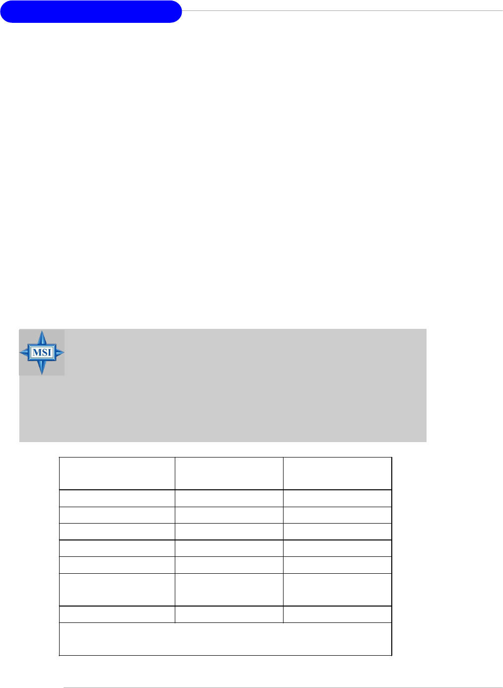
Revision History
Revision Revision History Date
V1.0 First release for PCB 1.X August 2003
with Intel® 848P & Intel® ICH5
V1.1 Audio driver updates October 2003
V2.0 First release for PCB 2.X February 2004
with Intel® 865PE/848P &
Intel® ICH5

iv
1. Always read the safety instructions carefully.
2. Keep this User’s Manual for future reference.
3. Keep this equipment away from humidity.
4. Lay this equipment on a reliable flat surface before setting it up.
5. The openings on the enclosure are for air convection hence protects the equip-
ment from overheating. Do not cover the openings.
6. Make sure the voltage of the power source and adjust properly 110/220V be-
fore connecting the equipment to the power inlet.
7. Place the power cord such a way that people can not step on it. Do not place
anything over the power cord.
8. Always Unplug the Power Cord before inserting any add-on card or module.
9. All cautions and warnings on the equipment should be noted.
10. Never pour any liquid into the opening that could damage or cause electrical
shock.
11. If any of the following situations arises, get the equipment checked by a service
personnel:
hThe power cord or plug is damaged.
hLiquid has penetrated into the equipment.
hThe equipment has been exposed to moisture.
hThe equipment has not work well or you can not get it work according to
User’s Manual.
hThe equipment has dropped and damaged.
hThe equipment has obvious sign of breakage.
12. Do not leave this equipment in an environment unconditioned, storage
temperature above 600 C (1400F), it may damage the equipment.
Safety Instructions
CAUTION: Danger of explosion if battery is incorrectly replaced.
Replace only with the same or equivalent type recommended by the
manufacturer.
Technical Support
If a problem arises with your system and no solution can be obtained from the user’s
manual, please contact your place of purchase or local distributor. Alternatively,
please try the following help resources for further guidance.
h Visit the MSI homepage & FAQ site for technical guide, BIOS updates, driver
updates, and other information: http://www.msi.com.tw & http://www.msi.
com.tw/program/service/faq/faq/esc_faq_list.php
h Contact our technical staff at: support@msi.com.tw
v
CONTENTS
FCC-B Radio Frequency Interference Statement ........................................................ ii
Copyright Notice ........................................................................................................... iii
Revision History ............................................................................................................ iii
Safety Instructions ...................................................................................................... iv
Technical Support ........................................................................................................ iv
Chapter 1. Getting Started................................................................................... 1-1
Mainboard Specifications .................................................................................. 1-2
Mainboard Layout .............................................................................................. 1-4
Chapter 2. Hardware Setup ................................................................................. 2-1
Quick Components Guide .................................................................................. 2-2
Central Processing Unit: CPU ............................................................................ 2-3
Example of CPU Core Speed Derivation Procedure ................................. 2-3
Memory Speed/CPU FSB Support Matrix .................................................. 2-3
CPU Installation Procedures for Socket 478............................................. 2-5
Installing the CPU Fan ................................................................................. 2-5
Memory ............................................................................................................... 2-7
Introduction to DDR SDRAM....................................................................... 2-7
DDR Population Rules ................................................................................. 2-7
Dual-channel DDR Introduction .................................................................. 2-8
Installing DDR Modules ............................................................................... 2-8
Power Supply ..................................................................................................... 2-9
ATX 20-Pin Power Connector: ATX1 ......................................................... 2-9
ATX 12V Power Connector: JPW1............................................................ 2-9
Back Panel ........................................................................................................ 2-10
Mouse Connector ..................................................................................... 2-10
Keyboard Connector ................................................................................ 2-10
Serial Port Connector: COM A .................................................................. 2-11
USB Connectors....................................................................................... 2-11
SPDIF-out Port Connector ........................................................................ 2-11
RJ-45 LAN Jack: 10/100 LAN (8100C) /Giga-bit LAN (8110S)
(Optional)..................................................................... 2-12
Audio Port Connectors ............................................................................. 2-12
Parallel Port Connector: LPT1 .................................................................. 2-13
Connectors ....................................................................................................... 2-14
Floppy Disk Drive Connector: FDD1 ........................................................ 2-14
Fan Power Connectors: CPUFAN1/SYSFAN1 ........................................ 2-14
vi
CD-In Connector: CD1 .............................................................................. 2-14
ATA100 Hard Disk Connectors: IDE1 & IDE2 ........................................... 2-15
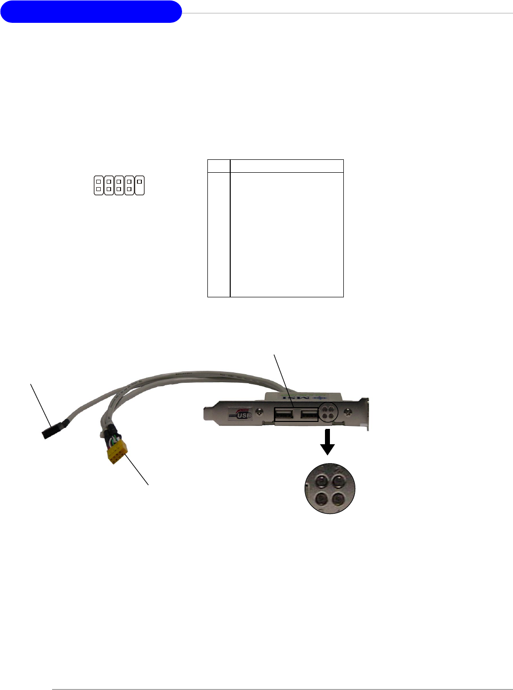
Front USB Connectors: JUSB2 & JUSB3 ................................................ 2-15
Serial ATA HDD Connectors: SATA1, SATA2 .......................................... 2-16
S-Bracket (SPDIF) Connector: JSP1 (Optional) ...................................... 2-17
Front Panel Connectors: JFP1 & JFP2..................................................... 2-18
Front Panel Audio Connector: JAUD1 ..................................................... 2-19
D-Bracket™ 2 Connector: JDB1 (Optional) ............................................ 2-20
Jumpers ............................................................................................................ 2-21
Clear CMOS Jumper: JBAT1 .................................................................... 2-21
Slots .................................................................................................................. 2-22
AGP (Accelerated Graphics Port) Slot ................................................... 2-22
PCI (Peripheral Component Interconnect) Slots...................................... 2-22
PCI Interrupt Request Routing .................................................................. 2-22
Chapter 3. BIOS Setup ........................................................................................... 3-1
Entering Setup .................................................................................................... 3-2
Selecting the First Boot Device ................................................................. 3-2
Control Keys ............................................................................................... 3-3
Getting Help ................................................................................................ 3-3
Main Menu ................................................................................................... 3-3
Default Settings .......................................................................................... 3-3
The Main Menu ................................................................................................... 3-4
Standard CMOS Features .................................................................................. 3-6
Advanced BIOS Features .................................................................................. 3-8
Advanced Chipset Features ........................................................................... 3-11
Power Management Features ......................................................................... 3-13
PNP/PCI Configurations .................................................................................... 3-16
Integrated Peripherals ...................................................................................... 3-19
PC Health Status .............................................................................................. 3-23
Frequency/Voltage Control .............................................................................. 3-24
Set Supervisor/User Password ...................................................................... 3-27
Load High Performance/BIOS Setup Defaults ................................................ 3-28

1-1
Getting Started
Chapter 1. Getting
Started
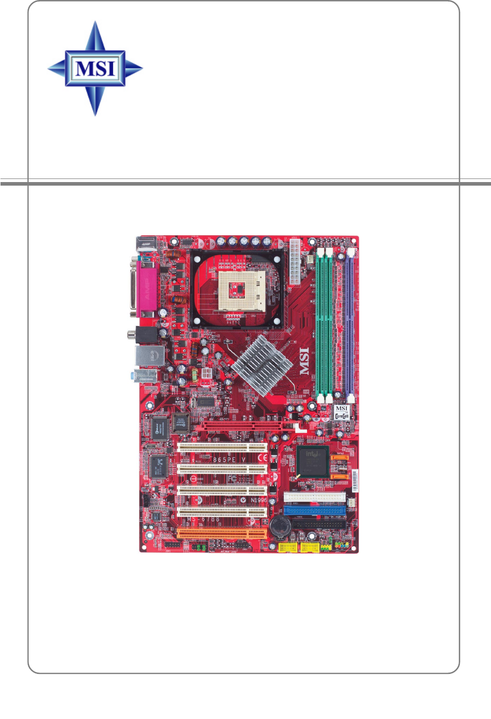
Thank you for choosing the 865PE Neo2-V / 848P Neo-V
Series (MS-6788) v2.X ATX mainboard. The 865PE Neo2-V / 848P
Neo-V Series is based on Intel® 865PE / 848P and ICH5 chipsets
for optimal system efficiency. Designed to fit the advanced Intel®
Pentium® 4 processors in 478 pin package, the 865PE Neo2-V
/ 848P Neo-V Series delivers a high performance and profes-
sional desktop platform solution.
Getting Started

1-2
MS-6788 ATX Mainboard
Mainboard Specifications
CPU
h Supports Intel® P4 Northwood / Prescott (Socket 478) processors.
h FSB 400MHz (for Northwood only) / 533MHz / 800MHz depending on the North
Bridge integrated.
h Supports up to 3.4GHz or higher speed P4 processor.
(For the latest information about CPU, please visit http://www.msi.com.tw/program/
products/mainboard/mbd/pro_mbd_cpu_support.php)
Chipset
h Intel® 865PE / 848P chipset
- Supports 400/533/800MHz Intel NetBurst micro-architecture bus.
- Supports AGP 8X/4X interface.
- Supports DDR266/333/400 memory interface.
h Intel® ICH5 chipset
- 8 Hi-Speed USB ports (USB2.0/1.1) controller, 480Mb/sec.
- 2 Serial ATA/150 ports.
- 2 channel Ultra ATA 100 bus Master IDE controller.
- PCI Master v2.3.
- I/O APIC.
Main Memory
hSupports bandwidth up to 3.2 GB/s (DDR 400) for single-channel mode and 6.
4GB/s (DDR 400) for dual-channel mode (for 865PE only).
hSupports two (for 848P) / three (for 865PE) unbuffered DIMM of 2.5 Volt DDR
SDRAM
hSupports up to 2GB (for 848P) / 3GB (for 865PE) memory size without ECC.
hSupports only x8, x16 DDR devices.
hSupports Dual-channel (for 865PE only) DDR 266/333/400 (based on DIMM 1.3).
(For the updated supporting memory modules, please visit http://www.msi.com.tw/
program/products/mainboard/mbd/pro_mbd_trp_list.php.)
Slots
hOne AGP slot supports 8x/4x.
hFive 32-bit v2.3 Master PCI bus slots (supports 3.3v/5v PCI bus interface).
On-Board IDE
h Dual Ultra DMA 66/100 IDE controllers integrated in ICH5.
- Supports PIO, Bus Master operation modes.
- Can connect up to four Ultra ATA drives.
h Serial ATA/150 controller integrated in ICH5.
- Up to 150MB/sec transfer rate.
- Can connect up to 2 Serial ATA drives.

1-3
Getting Started
On-Board Peripherals
h On-Board Peripherals includes:
- 1 floppy port supports 1 FDDs with 360K, 720K, 1.2M, 1.44M and 2.88Mbytes
- 1 serial port COM1
- 1 parallel port supports SPP/EPP/ECP mode
- 8 USB 2.0 ports (Rear * 4/ Front * 4)
- 1 Line-In/Line-Out/Mic-In port
- 1 RJ45 LAN jack (Optional)
- 1 RCA SPDIF Out
Audio
h AC’97 link controller integrated in ICH5.
h 6 channels software audio codec ALC655.
- Compliance with AC97 v2.2 Spec.
- Meet PC2001 audio performance requirement.
LAN (Optional)
h Realtek® 8110S/8100C Dual layout.
- Integrated Fast Ethernet MAC and PHY in one chip.
- Supports 10Mb/s, 100Mb/s and 1000Mb/s (1000Mb/s is only for Realtek 8110S)
auto-negotiation operation.
- Compliant with PCI v2.2.
- Supports ACPI Power Management.
BIOS
h The mainboard BIOS provides “Plug & Play” BIOS which detects the peripheral
devices and expansion cards of the board automatically.
h The mainboard provides a Desktop Management Interface (DMI) function which
records your mainboard specifications.
Dimension
h ATX Form Factor: 29.5 cm (L) x 21.0 cm (W).
Mounting
h 6 mounting holes.
1-4
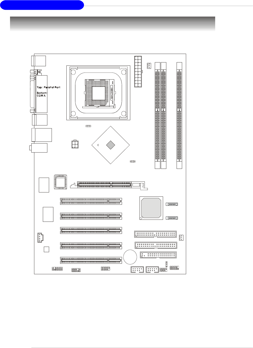
MS-6788 ATX Mainboard
Mainboard Layout
865PE Neo2-V (MS-6788 v2.X) ATX Mainboard
Intel
865PE
chipset
SYSFAN1
CPUFAN1
JSP1
JAUD1
JDB1
ATX Power
Supply
IDE 1
IDE 2
Winbond
W83627THF
Realtek
8110S/8100C
Top : mouse
Bottom: keyboard
T:LAN jack (Optional)
B:USB ports
T:SP DI F O ut
B:USB ports
CD1
JPW1
JBAT1
Codec
T:Line-In
M:
B:Mic
Line-Out
FDD1
AGP Slot
USB2 USB3 JFP1
SATA1
SATA2
JFP2
BATT
+
ICH 5
PCI Slot 5
PCI Slot 4
PCI Slot 3
PCI Slot 2
PCI Slot 1
DIMM 1
DIMM 3
BIOS
DIMM 2

1-5
Getting Started
848P Neo-V (MS-6788 v2.X) ATX Mainboard
Intel
848P
chipset
SYSFAN1
CPUFAN1
JSP1
JAUD1
JDB1
ATX Power
Supply
IDE 1
IDE 2
Winbond
W83627THF
Realtek
8110S/8100C
Top : mouse
Bottom: keyboard
T:LAN jack (Optional)
B:USB ports
T:SP DI F O ut
B:USB ports
CD1
JPW1
JBAT1
Codec
T:Line-In
M:
B:Mic
Line-Out
FDD1
AGP Slot
USB2 USB3 JFP1
SATA1
SATA2
JFP2
BATT
+
ICH 5
PCI Slot 5
PCI Slot 4
PCI Slot 3
PCI Slot 2
PCI Slot 1
DIMM 1
BIOS
DIMM 2

2-1
Hardware Setup
Chapter 2. Hardware
Setup
This chapter tells you how to install the CPU, memory modules, and
expansion cards, as well as how to setup the jumpers on the mainboard.
Also, it provides the instructions on connecting the peripheral devices, such
as the mouse, keyboard, etc.
While doing the installation, be careful in holding the components
and follow the installation procedures.
Hardware Setup
2-2
MS-6788 ATX Mainboard
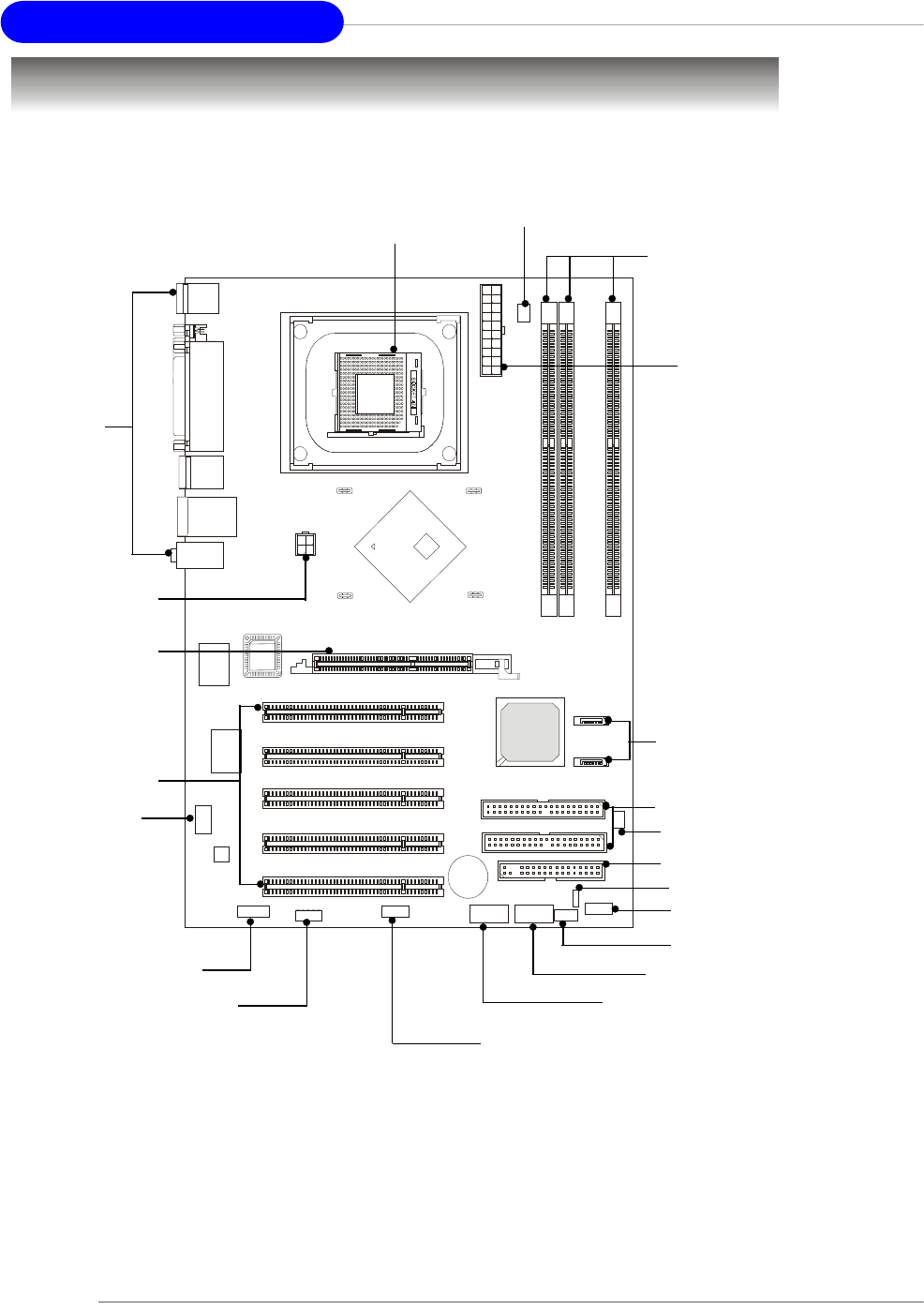
Quick Components Guide
DDR DIMMs, p.2-7
CPU, p.2-3
Back Panel
I/O, p.2-10
JDB1, p.2-20
JSP1, p.2-17
JFP1, p.2-18
AGP Slot, p.2-22
PCI Slots, p.2-22
CPUFAN1, p.2-14
SYSFAN1, p.2-14
JFP2, p.2-18
JAUD1, p.2-19
CD1, p.2-14
JUSB3, p.2-15
JUSB2, p.2-15
JBAT1, p.2-21
ATX1, p.2-9
FDD1, p.2-14
IDE1, IDE2, p.2-16
SATA1, SATA2, p.2-16
JPW1, p.2-9
2-3
Hardware Setup
Central Processing Unit: CPU
The mainboard supports Intel® Pentium® 4 processors in the 478 pin package.
The mainboard uses a CPU socket called PGA478 for easy CPU installation. When
you are installing the CPU, make sure the CPU has a heat sink and a cooling fan
attached on the top to prevent overheating. If you do not have the heat sink
and cooling fan, contact your dealer to purchase and install them before turning on
the computer.
For the latest information about CPU, please visit http://www.msi.com.tw/
program/products/mainboard/mbd/pro_mbd_cpu_support.php
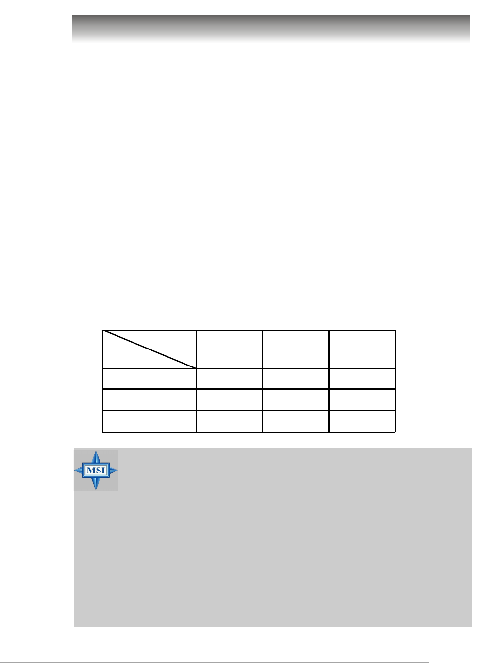
Memory Speed/CPU FSB Support Matrix
MSI Reminds You...
Overheating
Overheating will seriously damage the CPU and system, always make
sure the cooling fan can work properly to protect the CPU from
overheating.
Overclocking
This motherboard is designed to support overclocking. However,
please make sure your components are able to tolerate such abnor-
mal setting, while doing overclocking. Any attempt to operate beyond
product specifications is not recommended. We do not guarantee
the damages or risks caused by inadequate operation or be-
yond product specifications.
FSB
Memory DDR 266
400 MHz
DDR 333 DDR 400
533 MHz
800 MHz
OK N/A
OK OK
OK OK
N/A
N/A
N/A
Example of CPU Core Speed Derivation Procedure
If CPU Clock = 200MHz
Core/Bus ratio = 12
then CPU core speed = Host Clock x Core/Bus ratio
= 200MHz x 12
= 2.4 GHz
2-4
MS-6788 ATX Mainboard
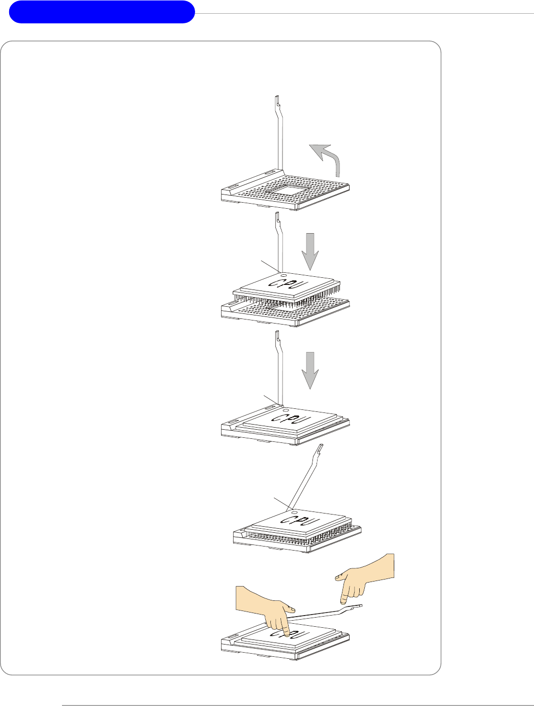
CPU Installation Procedures for Socket 478
1. Please turn off the power and
unplug the power cord before
installing the CPU.
2. Pull the lever sideways away
from the socket. Make sure to
raise the lever up to a 90-de-
gree angle.
3. Look for the gold arrow. The gold
arrow should point towards the
lever pivot. The CPU can only fit
in the correct orientation.
4. If the CPU is correctly installed,
the pins should be completely
embedded into the socket and
can not be seen. Please note
that any violation of the correct
installation procedures may
cause permanent damages to
your mainboard.
5. Press the CPU down firmly into
the socket and close the lever.
As the CPU is likely to move while
the lever is being closed, al-
ways close the lever with your
fingers pressing tightly on top of
the CPU to make sure the CPU is
properly and completely embed-
ded into the socket.
Open Lever
90 degree
Sliding
Plate
Close
Lever
Press down
the CPU
Gold arrow
Gold arrow
Gold arrow
Correct CPU placement
Incorrect CPU placement
X
O
2-5
Hardware Setup
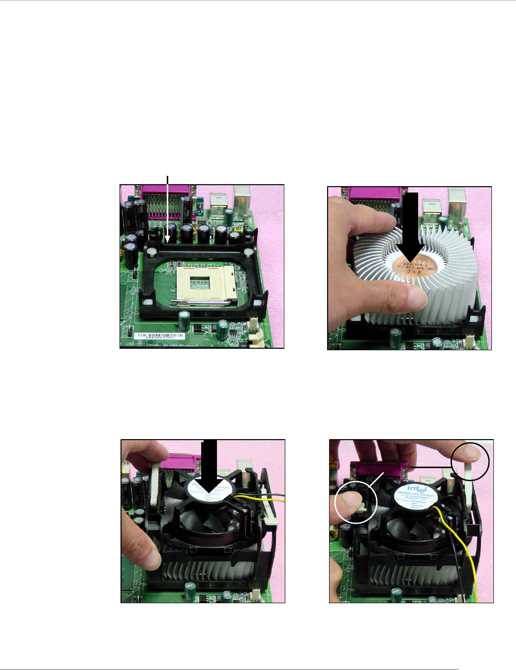
Installing the CPU Fan
As processor technology pushes to faster speeds and higher performance,
thermal management becomes increasingly important. To dissipate heat, you need to
attach the CPU cooling fan and heatsink on top of the CPU. Follow the instructions
below to install the Heatsink/Fan:
2. Position the heatsink onto the reten-
tion mechanism.
1. Locate the CPU and its retention
mechanism on the motherboard.
3. Mount the fan on top of the heatsink.
Press down the fan until its four clips
get wedged in the holes of the re-
tention mechanism.
4. Press the two levers down to fasten
the fan. Each lever can be pressed
down in only ONE direction.
retention mechanism
levers
2-6
MS-6788 ATX Mainboard
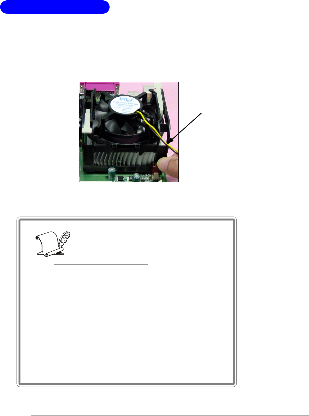
5. Connect the fan power cable from the mounted fan to the 3-pin fan power connec-
tor on the board.
fan power cable
NOTES

2-7
Hardware Setup
Memory
For 865PE Neo2-V: DIMM1~3,
max. memory 3GB.
For 848P Neo-V: DIMM1~2,
max. memory 2GB.
The mainboard provides 2/3 slots for 184-pin, 2.5V DDR DIMM modules and
supports the memory size up to 2 GB/3GB without ECC. You can install DDR266/
DDR333/DDR400 DDR SDRAM modules on the DDR DIMM slots. To operate properly,
at least one DIMM module must be installed.
For the updated supporting memory modules, please visit http://www.msi.
com.tw/program/products/mainboard/mbd/pro_mbd_trp_list.php.
Introduction to DDR SDRAM
DDR (Double Data Rate) SDRAM is similar to conventional SDRAM, but doubles
the rate by transferring data twice per cycle. It uses 2.5 volts as opposed to 3.3 volts
used in SDR SDRAM, and requires 184-pin DIMM modules rather than 168-pin DIMM
modules used by SDR SDRAM. High memory bandwidth makes DDR an ideal solution
for high performance PC, workstations and servers.
DDR Population Rules
Install at least one DIMM module on the slots. Each DIMM slot supports up to a
maximum size of 1GB. Users can install either single- or double-sided modules to
meet their own needs.
For 848PV, it supports only single-channel DDR. For 865PEV, it supports both
single-channel & dual-channel DDR.
DIMM1
DIMM2
DIMM3
2-8
MS-6788 ATX Mainboard
Dual-channel DDR Introduction
Please note that each DIMM can work respectively for single-channel
DDR, but there are some rules while using dual-channel DDR (Please refer to
the suggested DDR population table below). Inserting your memory modules in the
memory slot with different color will work as dual-channel DDR. Users may install
memory modules of different type and density on different-channel DDR DIMMs.
However, the same type and density memory modules are necessary while
using dual-channel DDR, or unstability may happen.
Please refer to the following table for detailed dual-channel DDR only for
865PE Neo2-V. Other combination not listed below will function as single-channel
DDR.
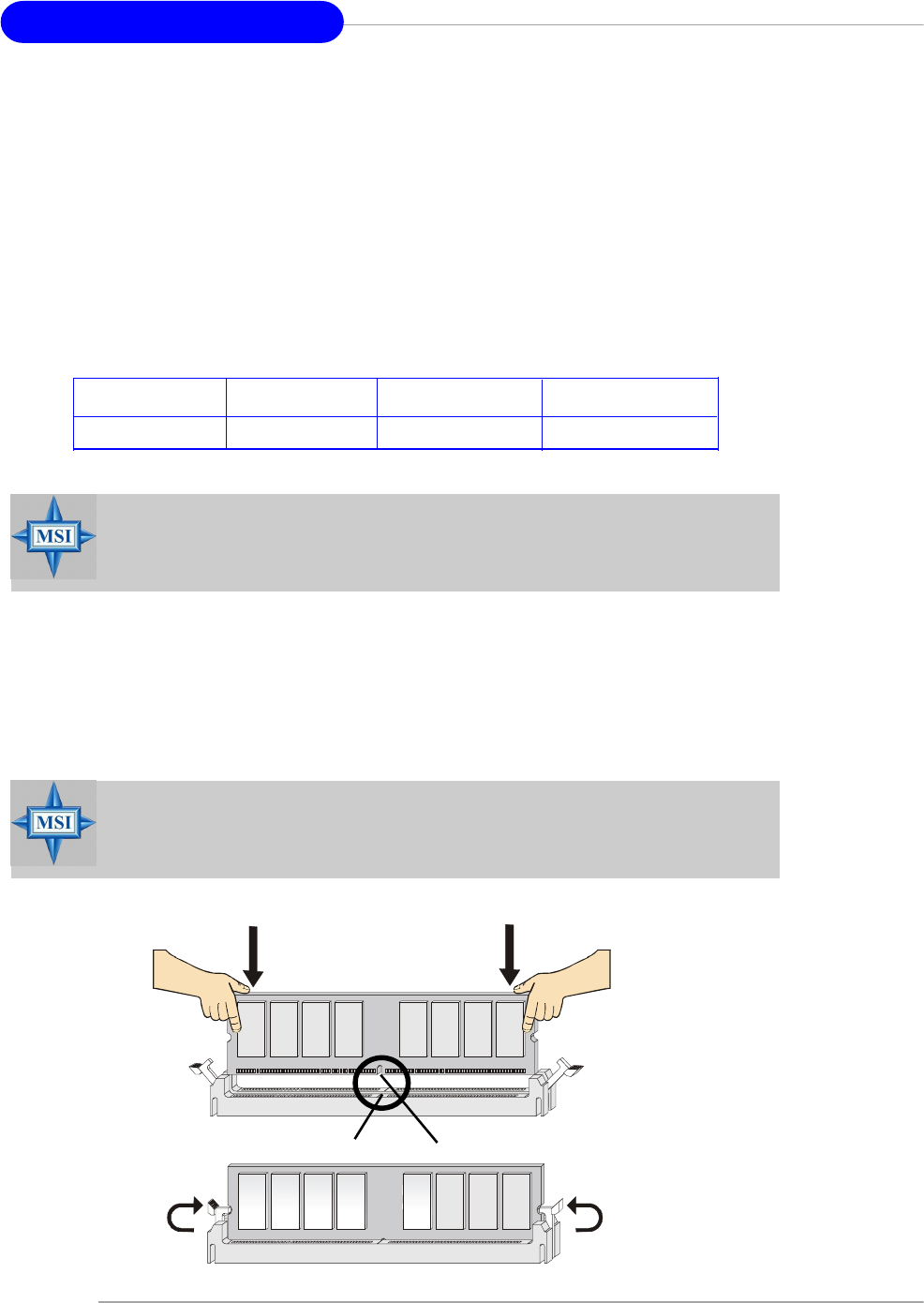
Installing DDR Modules
1. The DDR DIMM has only one notch on the center of module. The module will only
fit in the right orientation.
2. Insert the DIMM memory module vertically into the DIMM slot. Then push it in until
the golden finger on the memory module is deeply inserted in the socket.
3. The plastic clip at each side of the DIMM slot will automatically close.
Volt Notch
MSI Reminds You...
You can barely see the golden finger if the module is properly inserted
in the socket.
DIMM1 (Ch A) DIMM2 (Ch A) DIMM3 (Ch B) System Density
128MB~1GB 128MB~1GB 256MB~2GB
MSI Reminds You...
Dual-channel DDR for 865PE Neo2-V works ONLY in the DIMM1-DIMM3
combination listed in the table above.
2-9
Hardware Setup
Power Supply
The mainboard supports ATX power supply for the power system. Before
inserting the power supply connector, always make sure that all components are
installed properly to ensure that no damage will be caused.
ATX 20-Pin Power Connector: ATX1
This connector allows you to connect to an ATX power supply. To connect to
the ATX power supply, make sure the plug of the power supply is inserted in the
proper orientation and the pins are aligned. Then push down the power supply firmly
into the connector.
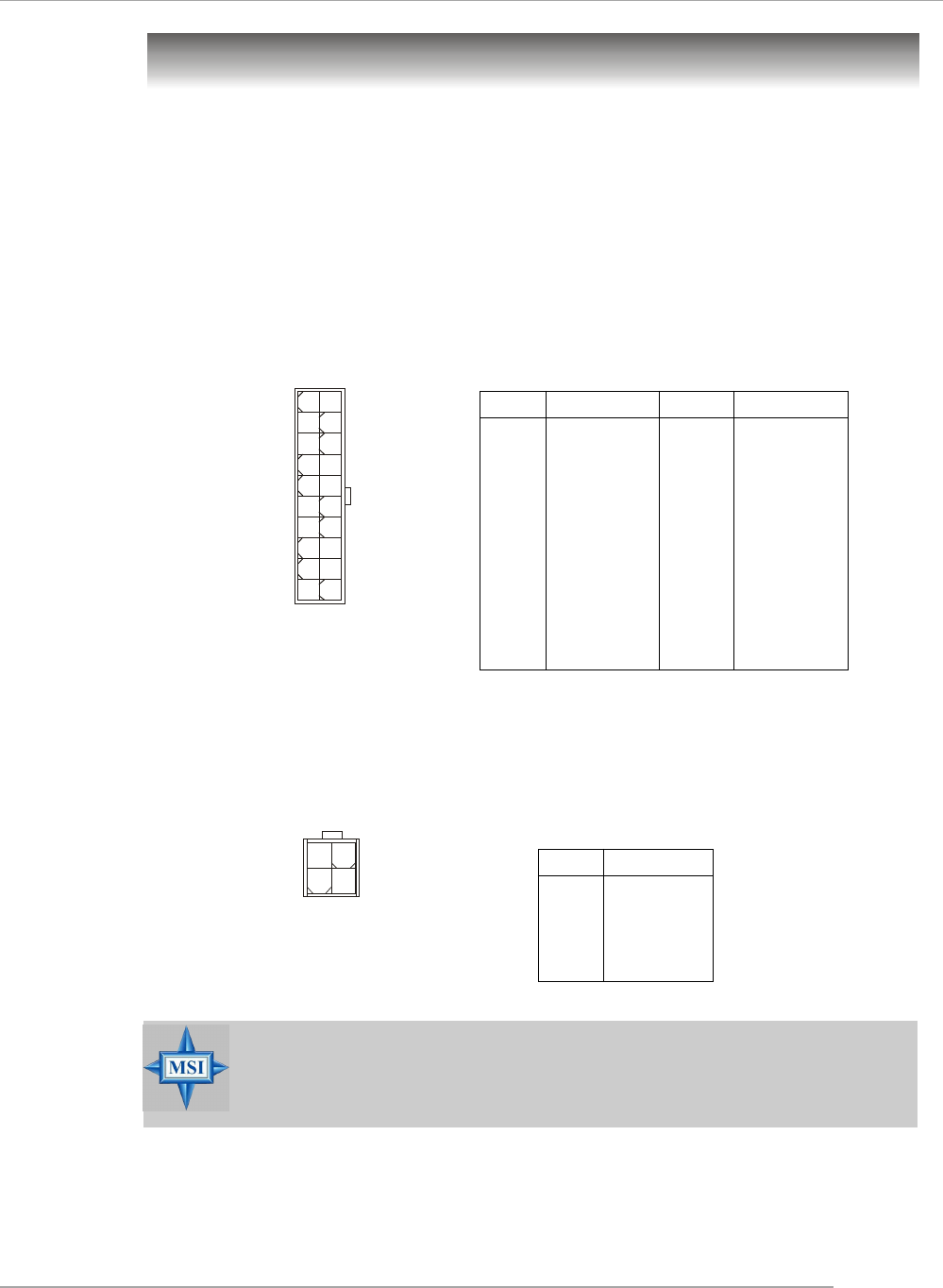
ATX 12V Power Connector: JPW1
This 12V power connector is used to provide power to the CPU.
PIN SIGNAL
1 GND
2 GND
3 12V
4 12V
JPW1 Pin Definition
PIN SIGNAL
11 3.3V
12 -12V
13 GND
14 PS_ON
15 GND
16 GND
17 GND
18 -5V
19 5V
20 5V
PIN SIGNAL
1 3.3V
2 3.3V
3 GND
45V
5 GND
65V
7 GND
8 PW_OK
9 5V_SB
10 12V
ATX1 Pin Definition
JPW1
1
34
2
ATX1
10
1
20
11
MSI Reminds You...
Power supply of 300 (and up) watt is highly recommended for system
stability.
2-10
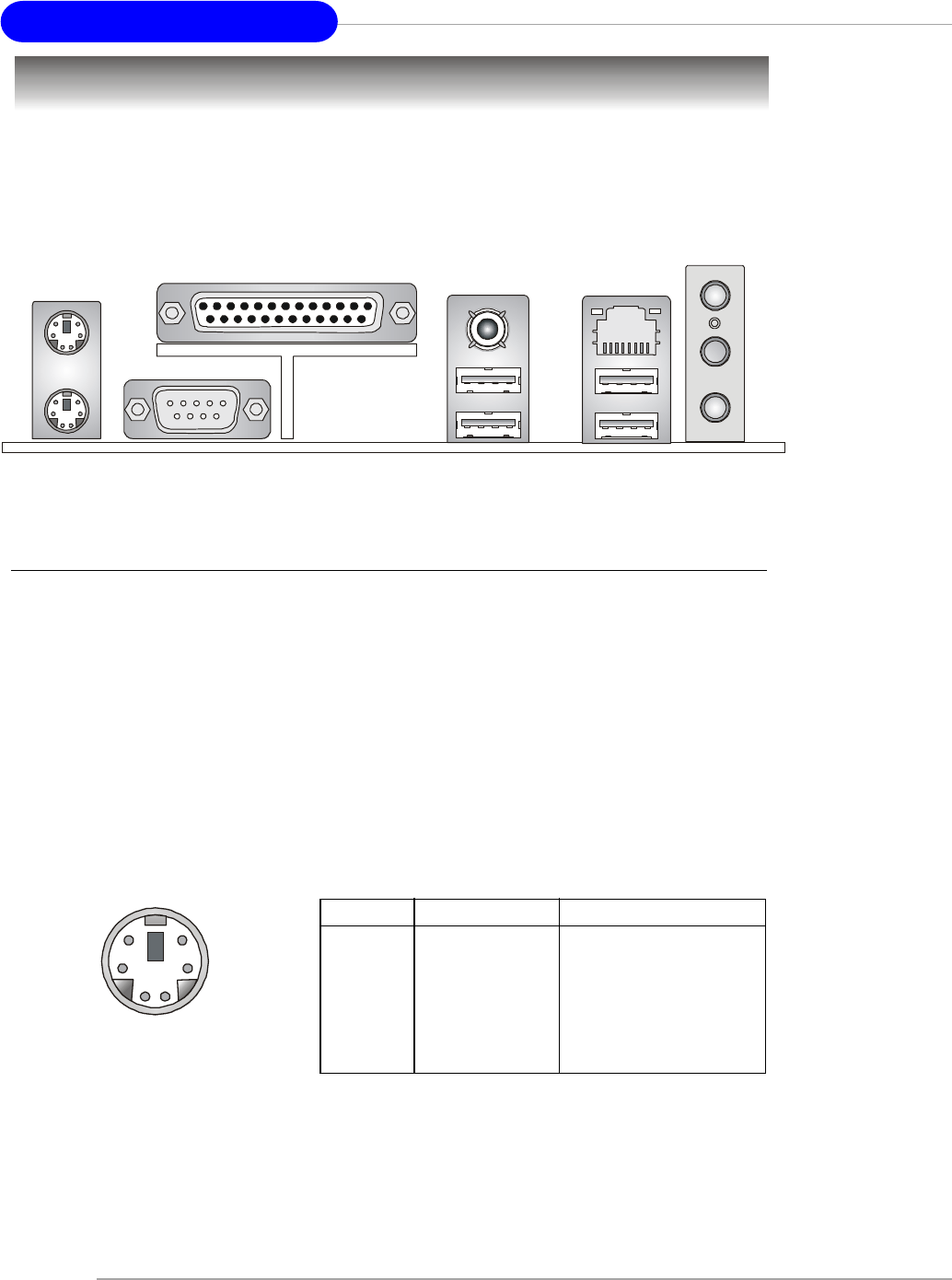
MS-6788 ATX Mainboard
The back panel provides the following connectors:
Back Panel
Mouse Connector
The mainboard provides a standard PS/2® mouse mini DIN connector for at-
taching a PS/2® mouse. You can plug a PS/2® mouse directly into this connector. The
connector location and pin assignments are as follows:
PS/2 Mouse (6-pin Female)
21
3
4
5
6
Keyboard Connector
The mainboard provides a standard PS/2® keyboard mini DIN connector for
attaching a PS/2® keyboard. You can plug a PS/2® keyboard directly into this connector.
PIN SIGNAL DESCRIPTION
1 Mouse DATA Mouse DATA
2 NC No connection
3 GND Ground
4 VCC +5V
5 Mouse Clock Mouse clock
6 NC No connection
Pin Definition
PS/2 Keyboard (6-pin Female)
Mouse Parallel
COM A USB Ports
Keyboard L-out
L-in
MIC
LAN
(Optional)
USB Ports
SPDIF-Out

2-11
Hardware Setup
USB Connectors
The mainboard provides a UHCI (Universal Host Controller Interface) Universal
Serial Bus root for attaching USB devices such as keyboard, mouse or other USB-
compatible devices. You can plug the USB device directly into the connector.
PIN SIGNAL DESCRIPTION
1 VCC +5V
2 -Data 0 Negative Data Channel 0
3 +Data0 Positive Data Channel 0
4 GND Ground
5 VCC +5V
6 -Data 1 Negative Data Channel 1
7 +Data 1 Positive Data Channel 1
8 GND Ground
USB Port Description
USB Ports
1 2 3 4
5 6 7 8
Serial Port Connector: COM A
The mainboard offers one 9-pin male DIN connector as serial port COM A. The
ports are 16550A high speed communication ports that send/receive 16 bytes FIFOs.
You can attach a serial mouse or other serial devices directly to the connectors.
PIN SIGNAL DESCRIPTION
1 DCD Data Carry Detect
2 SIN Serial In or Receive Data
3 SOUT Serial Out or Transmit Data
4 DTR Data Terminal Ready)
5 GND Ground
6 DSR Data Set Ready
7 RTS Request To Send
8 CTS Clear To Send
9 RI Ring Indicate
Pin Definition
9-Pin Male DIN Connector
1 2 3 4 5
6 7 8 9
SPDIF-out Port Connector
SPDIF-out is a jack for coaxial fiber connection for digital audio transmission.
SPDIF-out port
2-12
MS-6788 ATX Mainboard
Audio Port Connectors
Line Out is a connector for Speakers or Headphones. Line In is used for
external CD player, Tape player, or other audio devices. Mic is a connector for
microphones.
1/8” Stereo Audio Connectors Line Out
Line In
MIC
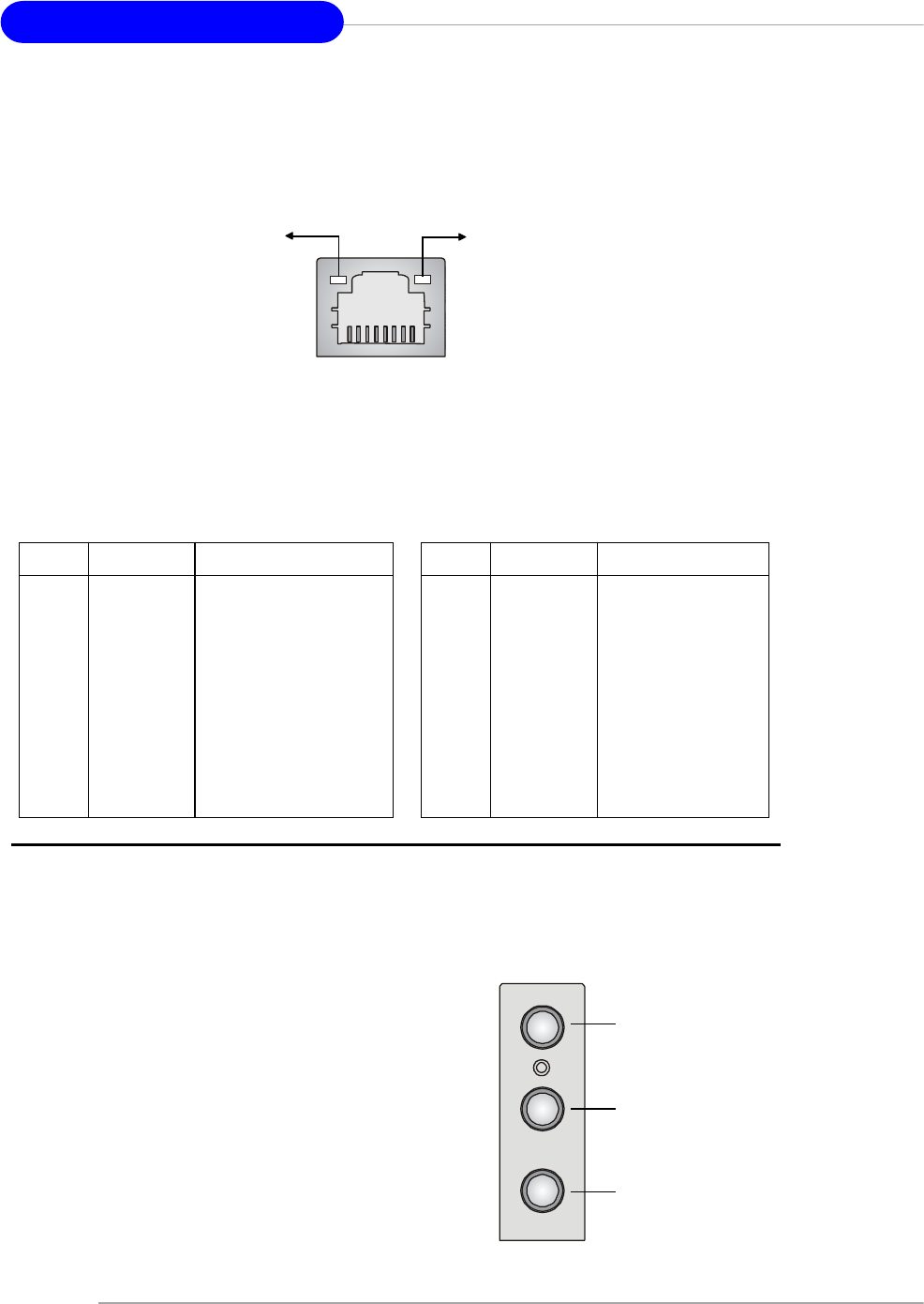
RJ-45 LAN Jack: 10/100 LAN (8100C) /Giga-bit LAN (8110S) (Optional)
The mainboard provides two standard RJ-45 jacks for connection to Local
Area Network (LAN). Giga-bit LAN enables data to be transferred at 1000, 100 or
10Mbps. You can connect a network cable to either LAN jack.
The pin assignments vary depending on the transfer rates: 10/100Mbps or
1000Mbps. Note that Pin 1/2, 3/6, 4/5, 7/8 must work in pairs. Please refer
to the following for details:
10/100 LAN Pin Definition Giga-bit LAN Pin Definition
PIN SIGNAL DESCRIPTION
1 D0P Differential Pair 0+
2 D0N Differential Pair 0-
3 D1P Differential Pair 1+
4 D2P Differential Pair 2+
5 D2N Differential Pair 2-
6 D1N Differential Pair 1-
7 D3P Differential Pair 3+
8 D3N Differential Pair 3-
PIN SIGNAL DESCRIPTION
1 TDP Transmit Differential Pair
2 TDN Transmit Differential Pair
3 RDP Receive Differential Pair
4 NC Not Used
5 NC Not Used
6 RDN Receive Differential Pair
7 NC Not Used
8 NC Not Used
RJ-45 LAN Jack
Link Indicator
8 1
Activity Indicator
2-13
Hardware Setup
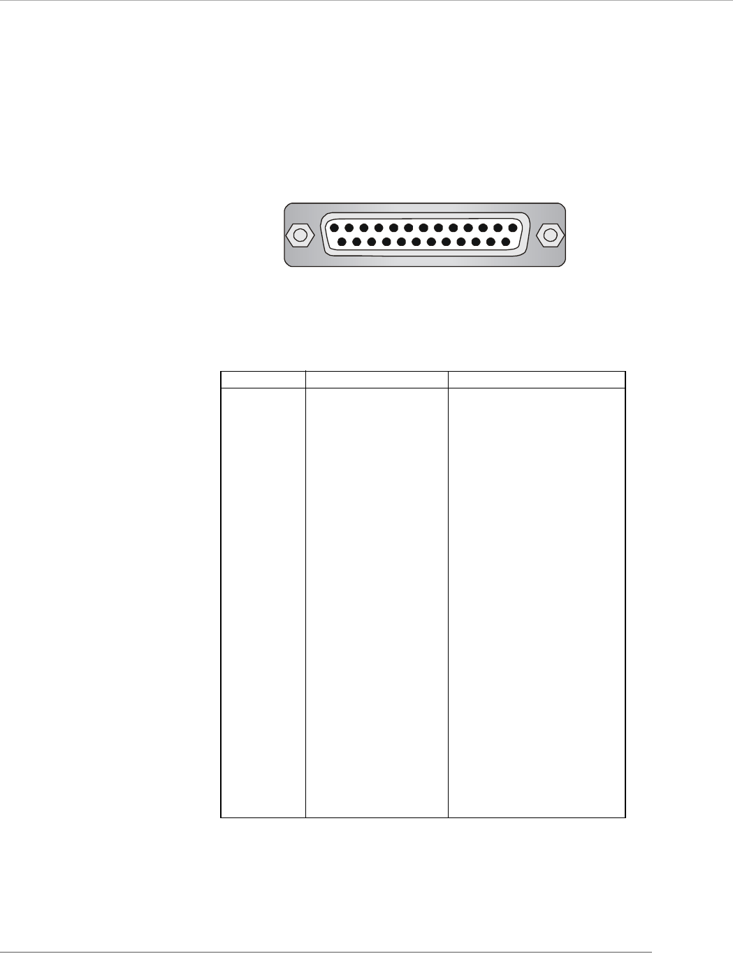
Parallel Port Connector: LPT1
The mainboard provides a 25-pin female centronic connector as LPT. A parallel
port is a standard printer port that supports Enhanced Parallel Port (EPP) and Ex-
tended Capabilities Parallel Port (ECP) mode.
13 1
14
25
PIN SIGNAL DESCRIPTION
1 STROBE Strobe
2 DATA0 Data0
3 DATA1 Data1
4 DATA2 Data2
5 DATA3 Data3
6 DATA4 Data4
7 DATA5 Data5
8 DATA6 Data6
9 DATA7 Data7
10 ACK# Acknowledge
11 BUSY Busy
12 PE Paper End
13 SELECT Select
14 AUTO FEED# Automatic Feed
15 ERR# Error
16 INIT# Initialize Printer
17 SLIN# Select In
18 GND Ground
19 GND Ground
20 GND Ground
21 GND Ground
22 GND Ground
23 GND Ground
24 GND Ground
25 GND Ground
Pin Definition
2-14
MS-6788 ATX Mainboard
The mainboard provides connectors to connect to FDD, IDE HDD, LAN, USB
Ports, and CPU/System/Power Supply FAN.
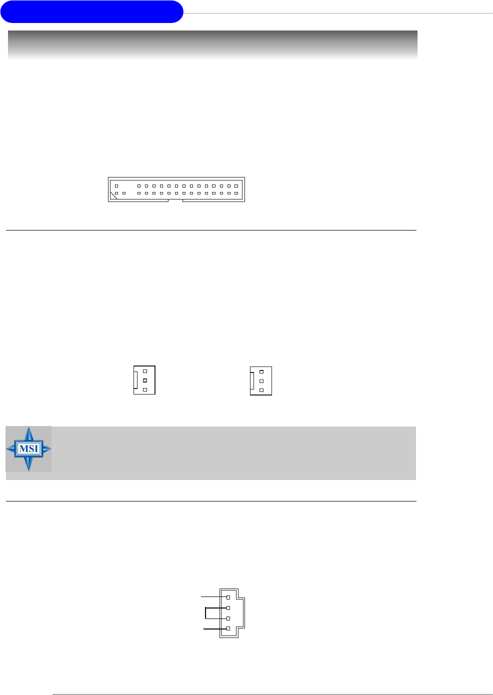
Floppy Disk Drive Connector: FDD1
The mainboard provides a standard floppy disk drive connector that supports
360K, 720K, 1.2M, 1.44M and 2.88M floppy disk types.
Connectors
FDD1
Fan Power Connectors: CPUFAN1/SYSFAN1
The CPUFAN1 (processor fan) and SYSFAN1 (system fan) support system
cooling fan with +12V. It supports three-pin head connector. When connecting the
wire to the connectors, always take note that the red wire is the positive and should
be connected to the +12V, the black wire is Ground and should be connected to GND.
If the mainboard has a System Hardware Monitor chipset on-board, you must use a
specially designed fan with speed sensor to take advantage of the CPU fan control.
CPUFAN1
Sensor
+12V
GND
SYSFAN1
Sensor
+12V
GND
CD-In Connector: CD1
The connector is for CD-ROM audio connector.
CD1
GND
L
R
MSI Reminds You...
1. Always consult the vendors for proper CPU cooling fan.
2. Please refer to the recommend CPU fans at Intel® official website.

2-15
Hardware Setup
ATA100 Hard Disk Connectors: IDE1 & IDE2
The mainboard has a 32-bit Enhanced PCI IDE and Ultra DMA 33/66/100 control-
ler that provides PIO mode 0~5, Bus Master, and Ultra DMA 33/66/100 function. You
can connect up to four hard disk drives, CD-ROM, 120MB Floppy and other devices.
These connectors support the provided IDE hard disk cable.
IDE1 (Primary IDE Connector)
The first hard drive should always be connected to IDE1. IDE1 can connect a Master
and a Slave drive. You must configure second hard drive to Slave mode by setting the
jumper accordingly.
IDE2 (Secondary IDE Connector)
IDE2 can also connect a Master and a Slave drive.
MSI Reminds You...
If you install two hard disks on cable, you must configure the second
drive to Slave mode by setting its jumper. Refer to the hard disk docu-
mentation supplied by hard disk vendors for jumper setting instructions.
IDE2
IDE1
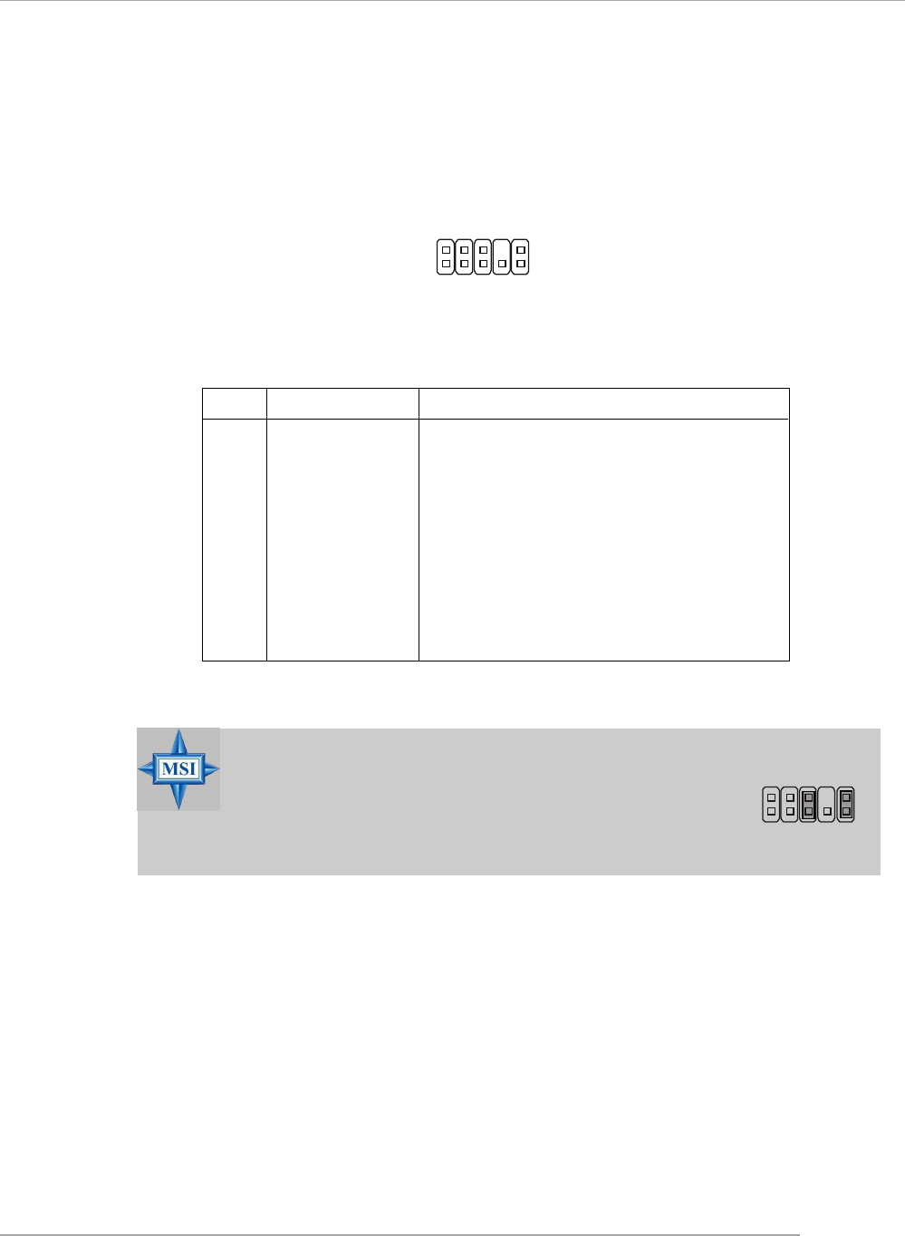
Front USB Connectors: JUSB2 & JUSB3
The mainboard provides two USB 2.0 pin headers JUSB2 & JUSB3 that are
compliant with Intel® I/O Connectivity Design Guide. USB 2.0 technology increases
data transfer rate up to a maximum throughput of 480Mbps, which is 40 times faster
than USB 1.1, and is ideal for connecting high-speed USB interface peripherals such
as USB HDD, digital cameras, MP3 players, printers, modems and the like.
PIN SIGNAL PIN SIGNAL
1 VCC 2 VCC
3 USB0- 4 USB1-
5 USB0+ 6 USB1+
7 GND 8 GND
9 Key (no pin) 10 USBOC
JUSB2 & JUSB3 Pin Definition
1
29
10
JUSB2 / JUSB3
2-16
MS-6788 ATX Mainboard
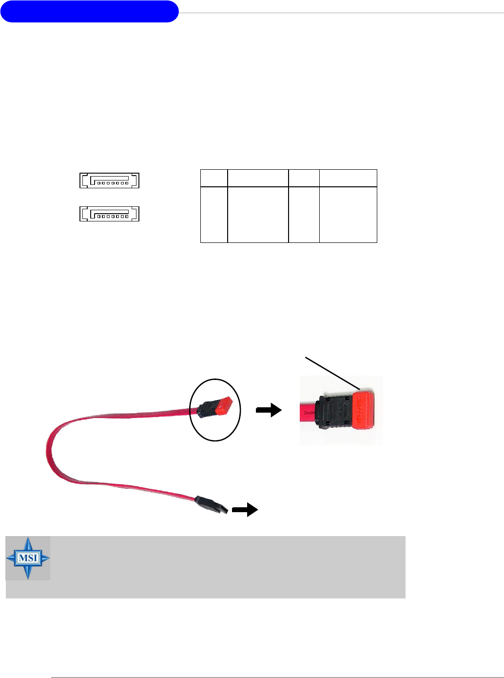
Serial ATA HDD Connectors: SATA1, SATA2
The mainboard provides dual high-speed Serial ATA interface ports. The ports
support 1st generation Serial ATA data rates of 150MB/s and are fully compliant with
Serial ATA 1.0 specifications. Each Serial ATA connector can connect to 1 hard disk
drive.
PIN SIGNAL PIN SIGNAL
1 GND 2 TXP
3 TXN 4 GND
5 RXN 6 RXP
7 GND
Pin Definition
Connect to SATA1 or SATA2
Take out the dust cover and
connect to the hard disk
devices
Optional Serial ATA cable
MSI Reminds You...
Please do not fold the Serial ATA cable into 90-degree angle. Otherwise,
the loss of data may occur during transmission.
SATA2
SATA1
7 1
2-17
Hardware Setup
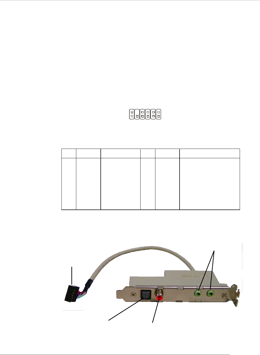
JSP1
1 11
12 2
PIN SIGNAL DESCRIPTION PIN SIGNAL DESCRIPTION
1 VCC5 VCC 5V 2 VDD3 VDD 3.3V
3 SPDFO S/PDIF output 4 (No Pin) Key
5 GND Ground 6 SPDFI S/PDIF input
7 LFE-OUT Audio bass output 8 SOUT-R Audio right surrounding output
9 CET-OUT Audio center output 10 SOUT-L Audio left surrounding output
11 GND Ground 12 GND Ground
JSP1 Pin Definition
Optional S-Bracket
SPDIF jack (optical) SPDIF jack (coaxial)
Analog Line-Out jack
Connect to JSP1
S-Bracket (SPDIF) Connector: JSP1 (Optional)
The connector allows you to connect a S-Bracket for Sony & Philips Digital
Interface (SPDIF). The S-Bracket offers 2 SPDIF jacks for digital audio transmission
(one for optical fiber connection and the other for coaxial), and 2 analog Line-Out
jacks for 4-channel audio output.
To attach the fiber-optic cable to optical SPDIF jack, you need to remove the
plug from the jack first. The two SPDIF jacks support SPDIF output only.
2-18
MS-6788 ATX Mainboard
Front Panel Connectors: JFP1 & JFP2
The mainboard provides two front panel connectors for electrical connection
to the front panel switches and LEDs. JFP1 is compliant with Intel® Front Panel I/O
Connectivity Design Guide.
1
29
10
JFP1
HDD
LED Reset
Switch
Power
LED Power
Switch
Power
LED
Speaker
1
27
8
JFP2
PIN SIGNAL DESCRIPTION
1 HD_LED_P Hard disk LED pull-up
2 FP PWR/SLP MSG LED pull-up
3 HD_LED_N Hard disk active LED
4 FP PWR/SLP MSG LED pull-up
5 RST_SW_N Reset Switch low reference pull-down to GND
6 PWR_SW_P Power Switch high reference pull-up
7 RST_SW_P Reset Switch high reference pull-up
8 PWR_SW_N Power Switch low reference pull-down to GND
9 RSVD_DNU Reserved. Do not use.
JFP1 Pin Definition
PIN SIGNAL PIN SIGNAL
1 GND 2 SPK-
3 SLED 4 BUZ+
5 PLED 6 BUZ-
7 NC 8 SPK+
JFP2 Pin Definition
2-19
Hardware Setup
Front Panel Audio Connector: JAUD1
The JAUD1 front panel audio connector allows you to connect to the
front panel audio and is compliant with Intel® Front Panel I/O Connectivity
Design Guide.
JAUD1
1
2
9
10
PIN SIGNAL DESCRIPTION
1 AUD_MIC Front panel microphone input signal
2 AUD_GND Ground used by analog audio circuits
3 AUD_MIC_BIAS Microphone power
4 AUD_VCC Filtered +5V used by analog audio circuits
5 AUD_FPOUT_R Right channel audio signal to front panel
6 AUD_RET_R Right channel audio signal return from front panel
7 HP_ON Reserved for future use to control headphone amplifier
8 KEY No pin
9 AUD_FPOUT_L Left channel audio signal to front panel
10 AUD_RET_L Left channel audio signal return from front panel
JAUD1 Pin Definition
MSI Reminds You...
If you don’t want to connect to the front audio header, pins
5 & 6, 9 & 10 have to be jumpered in order to have signal
output directed to the rear audio ports. Otherwise, the
Line-Out connector on the back panel will not function. 5
610
9
2-20
MS-6788 ATX Mainboard
D-Bracket™ 2 Connector: JDB1 (Optional)
The mainboard comes with a JDB1 connector for you to connect to D-Bracket™
2. D-Bracket™ 2 is a USB Bracket that supports both USB1.1 & 2.0 spec. It integrates
four LEDs and allows users to identify system problem through 16 various combina-
tions of LED signals. For definitions of 16 signal combinations, please refer to D-
Bracket™ 2 in Chapter 1.
Pin Signal
1 DBG1 (high for green color)
2 DBR1 (high for red color)
3 DBG2 (high for green color)
4 DBR2 (high for red color)
5 DBG3 (high for green color)
6 DBR3 (high for red color)
7 DBG4 (high for green color)
8 DBR4 (high for red color)
9 Key
10 NC
JDB1 Pin Definition
JDB1
1 9
2 10
D-Bracket™ 2
Connected to JUSB2 (the USB
pinheader in yellow color)
Connected to JDB1
LEDs
Depending on the optional bracket you buy, please
note there might be a Bluetooth Sticker to cover one
of the port, which marks “Do no remove, when
using bluetooth”.
2-21
Hardware Setup
The motherboard provides the following jumpers for you to set the computer’s
function. This section will explain how to change your motherboard’s function through
the use of jumpers.
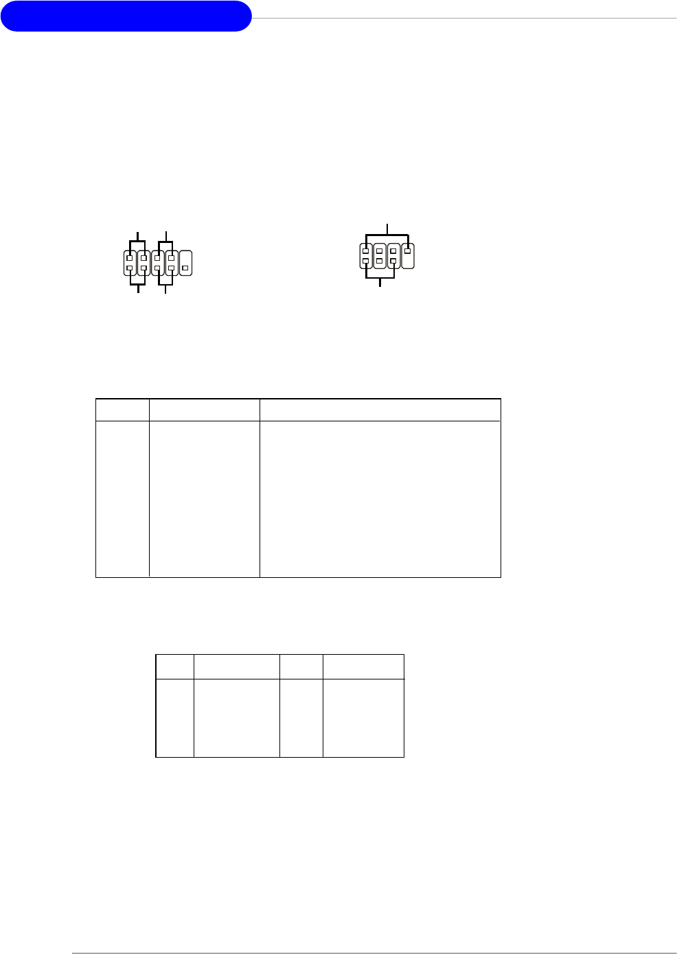
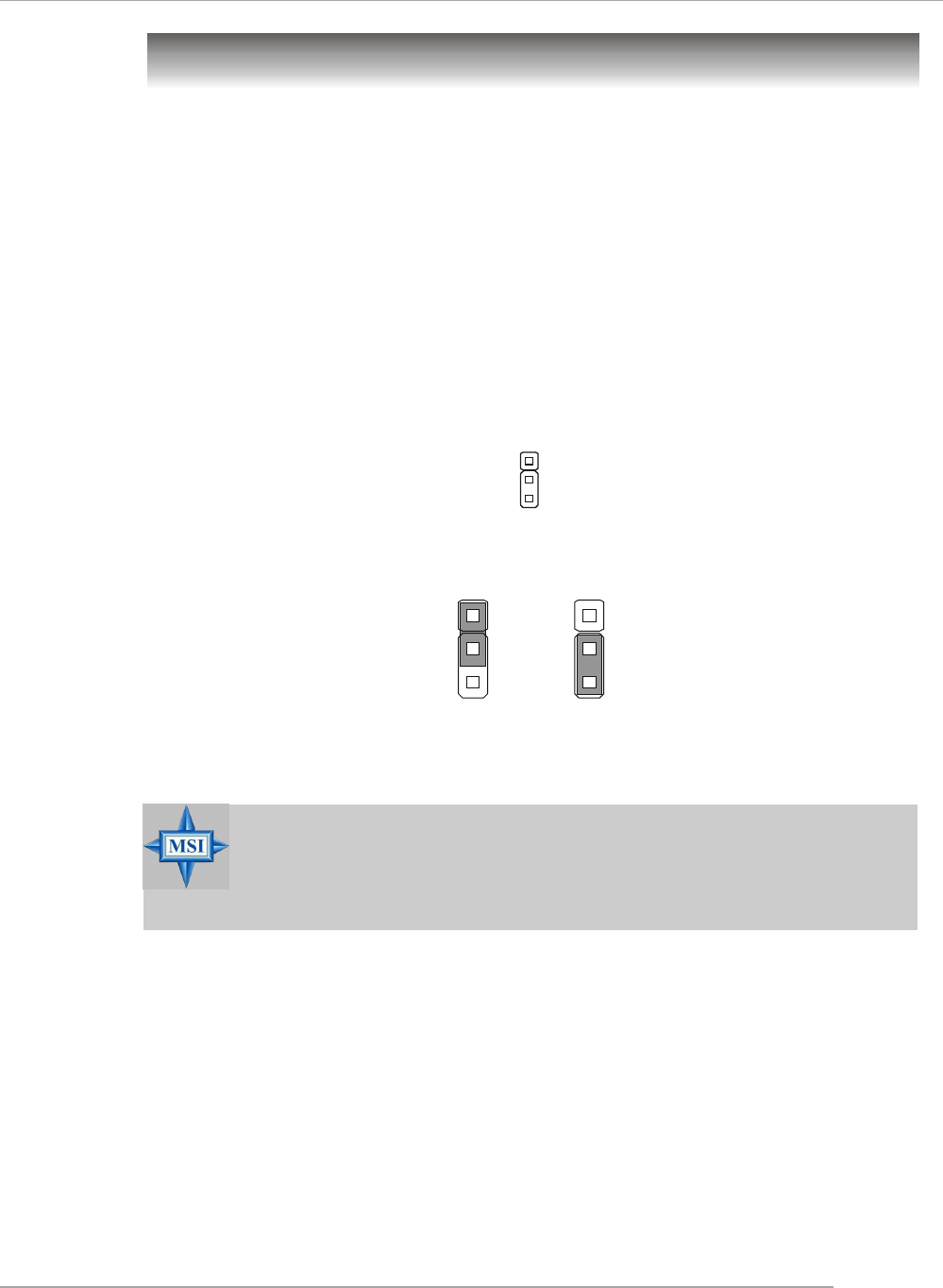
Clear CMOS Jumper: JBAT1
There is a CMOS RAM on board that has a power supply from external battery
to keep the data of system configuration. With the CMOS RAM, the system can
automatically boot OS every time it is turned on. If you want to clear the system
configuration, use the JBAT1 (Clear CMOS Jumper ) to clear data. Follow the instruc-
tions below to clear the data:
Jumpers
JBAT1
1
Clear Data
1
3
Keep Data
1
3
MSI Reminds You...
You can clear CMOS by shorting 2-3 pin while the system is off.
Then return to 1-2 pin position. Avoid clearing the CMOS while the
system is on; it will damage the mainboard.
2-22
MS-6788 ATX Mainboard
PCI Interrupt Request Routing
The IRQ, acronym of interrupt request line and pronounced I-R-Q, are hard-
ware lines over which devices can send interrupt signals to the microprocessor. The
PCI IRQ pins are typically connected to the PCI bus INT A# ~ INT D# pins as follows:
Slots
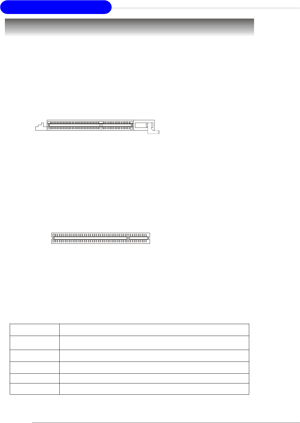
AGP (Accelerated Graphics Port) Slot
The AGP slot allows you to insert the AGP graphics card. AGP is an interface
specification designed for the throughput demands of 3D graphics. It introduces a
66MHz, 32-bit channel for the graphics controller to directly access main memory.
The slot supports 8x/4x AGP card.
PCI (Peripheral Component Interconnect) Slots
The PCI slots allow you to insert the expansion cards to meet your needs.
When adding or removing expansion cards, make sure that you unplug the power
supply first. Meanwhile, read the documentation for the expansion card to make any
necessary hardware or software settings for the expansion card, such as jumpers,
switches or BIOS configuration. The orange PCI slot (PCI5) also works as a
communcation slot, which allows you to insert the communcation card.
The motherboard provides one AGP slot and five 32-bit PCI bus slots.
PCI Slots
AGP Slot
Order 1 Order 2 Order 3 Order 4
PCI Slot 1 INT B# INT C# INT D# INT A#
PCI Slot 2 INT C# INT D# INT A# INT B#
PCI Slot 3 INT D# INT A# INT B# INT C#
PCI Slot 4 INT B# INT C# INT D# INT A#
PCI Slot 5 INT A# INT B# INT C# INT D#

3-1
BIOS Setup
Chapter 3. BIOS Setup
This chapter provides information on the BIOS Setup program and
allows you to configure the system for optimum use.
You may need to run the Setup program when:
An error message appears on the screen during the
system booting up, and requests you to run SETUP.
You want to change the default settings for customized
features.
BIOS Setup
MSI Reminds You...
1. The items under each BIOS category described in this chapter are
under continuous update for better system performance.
Therefore, the description may be slightly different from the latest
BIOS and should be held for reference only.
2. While booting up, the BIOS version is shown in the 1st line ap-
pearing after the memory counting. It is usually in the format:
example: W7005MS V2.0 091096
where:
1st digit refers to BIOS maker as A=AMI(R); W=AWARD(R)
2nd - 5th digit refers to the model number.
6th - 7th digit refers to the customer, MS=all standard customers.
V2.0 refers to the BIOS version.
091096 refers to the date this BIOS is released.

3-2
MS-6788 ATX Mainboard
Entering Setup
Power on the computer and the system will start POST (Power On Self Test)
process. When the message below appears on the screen, press <DEL> key to
enter Setup.
DEL: Setup F11: Boot Menu F12: Network boot TAB: Logo
If the message disappears before you respond and you still wish to enter
Setup, restart the system by turning it OFF and On or pressing the RESET button. You
may also restart the system by simultaneously pressing <Ctrl>, <Alt>, and <Delete>
keys.
Selecting the First Boot Device
You are allowed to select the 1st boot device without entering the BIOS setup
utility by pressing <F11>. When the same message as listed above appears on the
screen, press <F11> to trigger the boot menu.
The POST messages might pass by too quickly for you to respond in time. If
so, restart the system and press <F11> after around 2 or 3 seconds to activate the
boot menu similar to the following.
The boot menu will list all the bootable devices. Select the one you want to boot
from by using arrow keys, then press <Enter>. The system will boot from the se-
lected device. The selection will not make changes to the settings in the BIOS setup
utility, so next time when you power on the system, it will still use the original first
boot device to boot up.
Select First Boot Device
Floppy : 1st Floppy
IDE-0 : IBM-DTLA-307038
CDROM : ATAPI CD-ROM DRIVE 40X M
[Up/Dn] Select [RETURN] Boot [ESC] cancel

3-3
BIOS Setup
Control Keys
Getting Help
After entering the Setup utility, the first screen you see is the Main Menu.
Main Menu
The main menu displays the setup categories the BIOS supplies. You can use
the arrow keys ( ↑↓ ) to select the item. The on-line description for the selected setup
category is displayed at the bottom of the screen.
Default Settings
The BIOS setup program contains two kinds of default settings: the BIOS
Setup and High Performance defaults. BIOS Setup defaults provide stable perfor-
mance settings for all devices and the system, while High Performance defaults
provide the best system performance but may affect the system stability.
<↑>Move to the previous item
<↓>Move to the next item
<←>Move to the item in the left hand
<→>Move to the item in the right hand
<Enter> Select the item
<Esc> Jumps to the Exit menu or returns to the main menu from a
submenu
<+/PU> Increase the numeric value or make changes
<-/PD> Decrease the numeric value or make changes
<F7> Load BIOS Setup Defaults
<F9> Load High Performance Defaults
<F10> Save all the CMOS changes and exit
3-4
MS-6788 ATX Mainboard
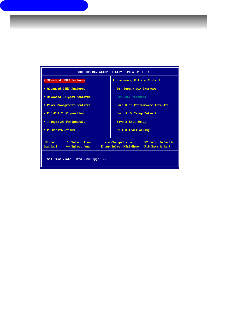
The Main Menu
Standard CMOS Features
Use this menu for basic system configurations, such as time, date etc.
Advanced BIOS Features
Use this menu to setup the items of AMI® special enhanced features.
Advanced Chipset Features
Use this menu to change the values in the chipset registers and optimize your system’s
performance.
Power Management Features
Use this menu to specify your settings for power management.
PNP/PCI Configurations
This entry appears if your system supports PnP/PCI.
Integrated Peripherals
Use this menu to specify your settings for integrated peripherals.
PC Health Status
This entry shows your PC health status.
Frequency/Voltage Control
Use this menu to specify your settings for frequency/voltage control.
Once you enter AMIBIOS NEW SETUP UTILITY, the Main Menu will appear on
the screen. The Main Menu displays twelve configurable functions and two exit
choices. Use arrow keys to move among the items and press <Enter> to enter the
sub-menu.

3-5
BIOS Setup
Set Supervisor Password
Use this menu to set Supervisor Password.
Set User Password
Use this menu to set User Password.
Load High Performance Defaults
Use this menu to load the BIOS values for the best system performance, but the
system stability may be affected.
Load BIOS Setup Defaults
Use this menu to load factory default settings into the BIOS for stable system perfor-
mance operations.
Save & Exit Setup
Save changes to CMOS and exit setup.
Exit Without Saving
Abandon all changes and exit setup.

3-6
MS-6788 ATX Mainboard
Standard CMOS Features
The items in Standard CMOS Features Menu includes some basic setup items.
Use the arrow keys to highlight the item and then use the <PgUp> or <PgDn> keys to
select the value you want in each item.
System Time
This allows you to set the system time that you want (usually the current time). The
time format is <hour> <minute> <second>.
System Date
This allows you to set the system to the date that you want (usually the current date).
The format is <month> <date> <year><day>.
month The month from Jan. through Dec.
date The date from 1 to 31 can be keyed by numeric
function keys.
year The year can be adjusted by users.
day Day of the week, from Sun to Sat, determined by
BIOS. Read-only.
Primary/Secondary/Third/Fourth IDE Master/Slave
Press PgUp/<+> or PgDn/<-> to select the hard disk drive type. The specification of
hard disk drive will show up on the right hand according to your selection.
Type Select how to define the HDD parameters
Cylinders Enter cylinder number
Heads Enter head number
Write Precompensation Enter write precomp cylinder
Sectors Enter sector number
Maximum Capacity Read the maximal HDD capacity

3-7
BIOS Setup
LBA Mode Select [Auto] for a hard disk > 512 MB under
Windows and DOS, or [Disabled] under
Netware and UNIX
Block Mode Select [Auto] to enhance the hard disk perfor-
mance
Fast Programmed I/O Select [Auto] to enhance hard disk performa-
Modes nce by optimizing the hard disk timing
32 Bit Transfer Mode Enable 32 bit to maximize the IDE hard disk data
transfer rate
Floppy Drive A:
This item allows you to set the type of the floppy drive installed. Available options:
[None], [360K, 5.25 in.], [1.2M, 5.25 in.], [720K, 3.5 in.], [1.44M, 3.5 in.], [2.88M, 3.5 in.].
3-8
MS-6788 ATX Mainboard
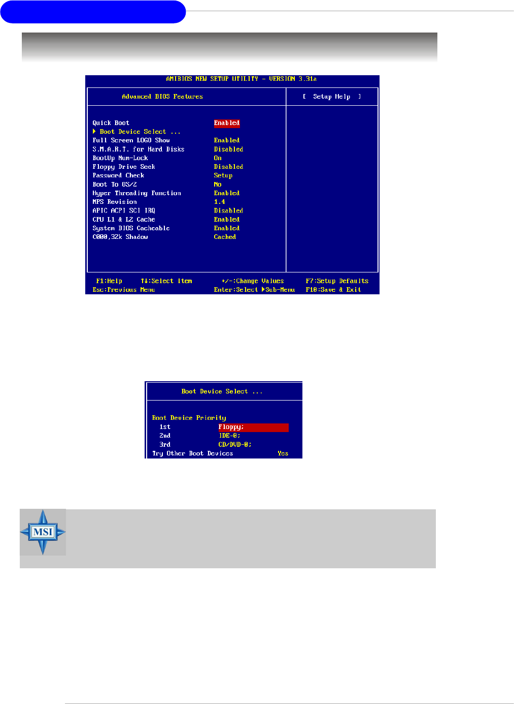
Advanced BIOS Features
Quick Boot
Setting the item to [Enabled] allows the system to boot within 5 seconds since it will
skip some check items. Available options: [Enabled], [Disabled].
Boot Device Select
Press <Enter> to enter the sub-menu screen.
1st/2nd/3rd Boot Device
The items allow you to set the sequence of boot devices where BIOS attempts
to load the disk operating system.
.
Try Other Boot Device
Setting the option to [Yes] allows the system to try to boot from other devices
if the system fails to boot from the 1st/2nd/3rd boot device.
Full Screen LOGO Show
This item enables you to show the company logo on the bootup screen. Settings are:
[Enabled] Shows a still image (logo) on the full screen at boot.
[Disabled] Shows the POST messages at boot.
MSI Reminds You...
Available settings for “1st/2nd/3rd Boot Device” vary depending on
the bootable devices you have installed. For example, if you did not
install a floppy drive, the setting “Floppy” does not show up.

3-9
BIOS Setup
S.M.A.R.T. for Hard Disks
This allows you to activate the S.M.A.R.T. (Self-Monitoring Analysis & Reporting
Technology) capability for the hard disks. S.M.A.R.T is a utility that monitors your disk
status to predict hard disk failure. This gives you an opportunity to move data from a
hard disk that is going to fail to a safe place before the hard disk becomes offline.
Settings: [Enabled], [Disabled].
BootUp Num-Lock
Toggle between [On] or [Off] to control the state of the NumLock key when the
system boots. When toggled [On], the numeric keypad generates numbers instead of
controlling cursor operations. Setting options:[On], [Off].
Floppy Drive Seek
This setting causes the BIOS to search for floppy disk drives at boot time. When
enabled, the BIOS will activate the floppy disk drives during the boot process: the
drive activity light will come on and the head will move back and forth once. First A:
will be done and then B: if it exists. Setting options: [Enabled], [Disabled].
Password Check
This specifies the type of AMIBIOS password protection that is implemented. Setting
options are described below.
Boot To OS/2
This allows you to run the OS/2® operating system with DRAM larger than 64MB.
When you choose [No], you cannot run the OS/2® operating system with DRAM
larger than 64MB. But it is possible if you choose [Yes].
Hyper Threading Function
This field is used to enable or disable the Intel Hyper Threading CPU function. Setting
to [Enabled] will increase the system performance. Settings: [Enabled], [Disabled].
Please disable this item if your operating system doesn’t support HT Function, or the
unreliability and instability may occur.
MSI Reminds You...
Enabling the functionality of Hyper-Threading Technology for your com-
puter system requires ALL of the following platform Components:
*CPU: An Intel® Pentium® 4 Processor with HT Technology;
*Chipset: An Intel® Chipset that supports HT Technology;
*BIOS: A BIOS that supports HT Technology and has it enabled;
*OS: An operating system that supports HT Technology. For
more information on Hyper-threading Technology, go
to: http://www.intel.com/info/hyperthreading
Option Description
[Setup] The password prompt appears only when end users try to run
Setup.
[Always] A password prompt appears every time when the computer is pow-
ered on or when end users try to run Setup.

3-10
MS-6788 ATX Mainboard
MPS Revision
This field allows you to select which MPS (Multi-Processor Specification) version to
be used for the operating system. You need to select the MPS version supported by
your operating system. To find out which version to use, consult the vendor of your
operating system. Settings: [1.4], [1.1].
APIC ACPI SCI IRQ
This field is used to enable or disable the APIC (Advanced Programmable Interrupt
Controller). Due to compliance to PC2001 design guide, the system is able to run in
APIC mode. Enabling APIC mode will expand available IRQs resources for the system.
Settings: [Enabled], [Disabled].
CPU L1 & L2 Cache
Cache memory is additional memory that is much faster than conventional DRAM
(system memory). When the CPU requests data, the system transfers the requested
data from the main DRAM into cache memory, for even faster access by the CPU. The
settings enable/disable the internal cache (also known as L1 or level 1 cache) and
external cache (also known as L2 or level 2 cache). Setting options: [Enabled],
[Disabled].
System BIOS Cacheable
Selecting [Enabled] allows caching of the system BIOS ROM at F0000h-FFFFFh,
resulting in better system performance. However, if any program writes to this
memory area, a system error may result. Setting options: [Enabled], [Disabled].
C000, 32k Shadow
This item specifies how the contents of the adapter ROM named in the item are
handled. Settings are described below:
Option Description
[Disabled] The specified ROM is not copied to RAM.
[Enabled] The contents of specified ROM are copied to RAM for faster
system performance.
[Cached] The contents of specified ROM are not only copied to RAM, the
contents of the ROM area can be written to and read from cache
memory.
3-11
BIOS Setup
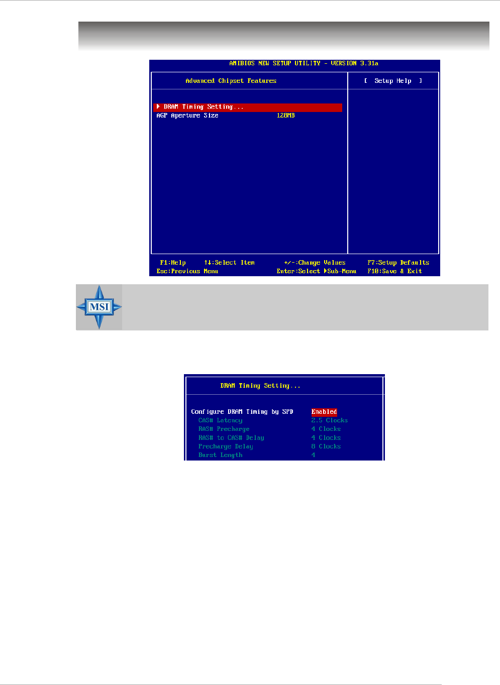
Advanced Chipset Features
DRAM Timing Setting...
Press <Enter> and to enter the sub-menu screen.
Configure SDRAM Timing by SPD
Selects whether DRAM timing is controlled by the SPD (Serial Presence Detect)
EEPROM on the DRAM module. Setting to [Enabled] enables the following fields
automatically to be determined by BIOS based on the configurations on the SPD.
Selecting [Disabled] allows users to configure these fields manually.
CAS# Latency
This controls the timing delay (in clock cycles) before SDRAM starts a read
command after receiving it. Settings: [2 Clocks], [2.5 Clocks]. [2 Clocks]
increases the system performance the most while [2.5 Clocks] provides
the most stable performance.
MSI Reminds You...
Change these settings only if you are familiar with the chipset.

3-12
MS-6788 ATX Mainboard
RAS# Precharge
This item controls the number of cycles for Row Address Strobe (RAS) to
be allowed to precharge. If insufficient time is allowed for the RAS to
accumulate its charge before DRAM refresh, refresh may be incomplete
and DRAM may fail to retain data. This item applies only when synchronous
DRAM is installed in the system. Available settings: [2 Clocks], [3 Clocks], [4
Clocks].
RAS# to CAS# Delay
When DRAM is refreshed, both rows and columns are addressed
separately. This setup item allows you to determine the timing of the tran-
sition from RAS (row address strobe) to CAS (column address strobe).
The less the clock cycles, the faster the DRAM performance. Setting options:
[2 Clocks], [3 Clocks], [4 Clocks].
Precharge Delay
The field specifies the idle cycles before precharging an idle bank. Settings:
[5 Clocks], [6 Clocks], [7 Clocks], [8 Clocks].
Burst Length
This setting allows you to set the size of Burst-Length for DRAM. Bursting
feature is a technique that DRAM itself predicts the address of the next
memory location to be accessed after the first address is accessed. To
use the feature, you need to define the burst length, which is the actual
length of burst plus the starting address and allows internal address coun-
ter to properly generate the next memory location. The bigger the size, the
faster the DRAM performance. Settings: [4], [8].
AGP Aperture Size (MB)
This setting controls just how much system RAM can be allocated to AGP for video
purposes. The aperture is a portion of the PCI memory address range dedicated to
graphics memory address space. Host cycles that hit the aperture range are for-
warded to the AGP without any translation. The option allows the selection of an
aperture size of [4MB], [8MB], [16MB], [32MB], [64MB], [128MB], and [256 MB].
3-13
BIOS Setup
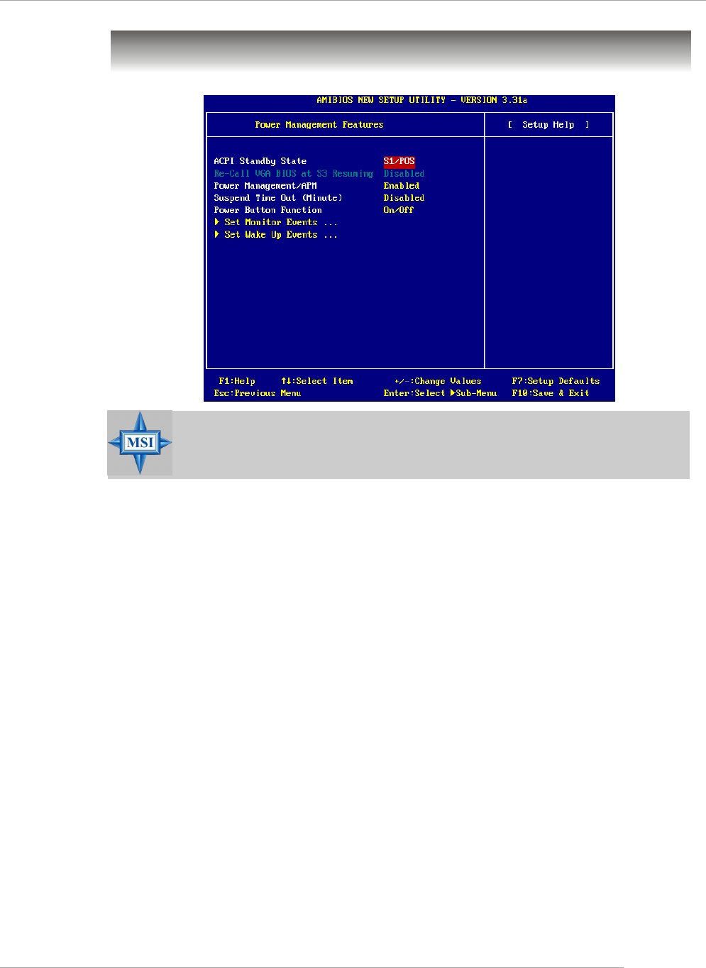
Power Management Features
ACPI Standby State
This item specifies the power saving modes for ACPI function. If your operating
system supports ACPI, such as Windows 98SE, Windows ME and Windows 2000,
you can choose to enter the Standby mode in S1 (POS) or S3 (STR) fashion through
the setting of this field. Options are:
[S1/POS] The S1 sleep mode is a low power state. In this state, no system
context is lost (CPU or chipset) and hardware maintains all system
context.
[S3/STR] The S3 sleep mode is a lower power state where the information of
system configuration and open applications/files is saved to main
memory that remains powered while most other hardware compo-
nents turn off to save energy. The information stored in memory will
be used to restore the system when a “wake up” event occurs.
[Auto] BIOS determines the best automatically.
Re-Call VGA BIOS at S3 Resuming
Selecting [Enabled] allows BIOS to call VGA BIOS to initialize the VGA card when
system wakes up (resumes) from S3 sleep state. The system resume time is short-
ened when you disable the function, but system will need an AGP driver to initialize
the VGA card. Therefore, if the AGP driver of the card does not support the initializa-
tion feature, the display may work abnormally or not function after resuming from S3.
MSI Reminds You...
S3-related functions described in this section are available only
when your BIOS supports S3 sleep mode.
3-14
MS-6788 ATX Mainboard
Power Management/APM
Setting to [Enabled] will activate an Advanced Power Management (APM) device to
enhance Max Saving mode and stop CPU internal clock. Settings: [Enabled], [Disabled].
Suspend Time Out (Minute)
If system activity is not detected for the length of time specified in this field, all
devices except CPU will be shut off. Settings: [Disabled], [1], [2], [4], [8], [10], [20],
[30], [40], [50], [60].
Power Button Function
This feature allows users to configure the Power Button function. Settings are:
[On/Off] The power button functions as a normal power-on/-off
button.
[Suspend] When you press the power button, the computer enters
the suspend/sleep mode, but if the button is pressed for
more than four seconds, the computer is turned off.
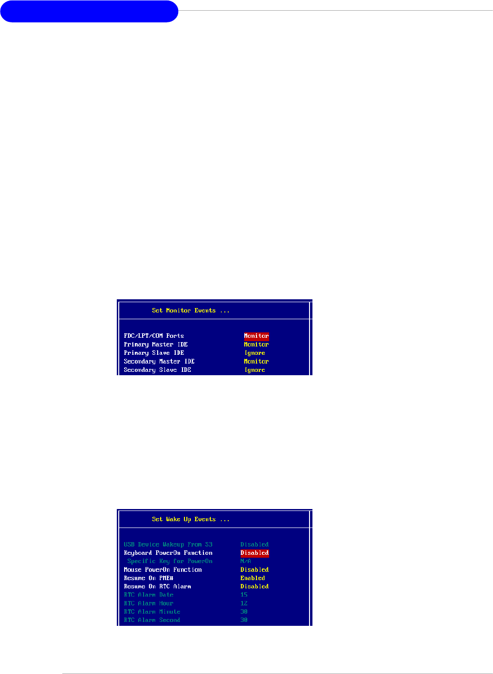
Set Monitor Events
Press <Enter> and the following sub-menu appears.
FDC/LPT/COM Ports, Primary/Secondary Master/Slave IDE
These items specify if the BIOS will monitor the activity of the specified hard-
ware peripherals or components. If set to [Monitor], any activity detected on the
specified hardware peripherals or components will wake up the system or
prevent the system from entering the power saving modes. Settings: [Monitor],
[Ignore].
Set WakeUp Events
Press <Enter> and the following sub-menu appears.

3-15
BIOS Setup
USB Device Wakeup From S3
This item allows the activity of the USB device to wake up the system from S3
(suspend to RAM) sleep state. Setting: [Enabled], [Disabled].
Keyboard PowerOn Function
This controls how and whether the PS/2 keyboard is able to power on the
system.You must type the password to power on the system. Settings:
[Disabled], [Any Key], [Specific Key].
Specific Key for PowerOn
Specify the password to enable for the Keyboard PowerOn Function
while setting to [Specific Key].
Mouse PowerOn Function
This controls how and whether the PS/2 mouse is able to power on the system.
Settings: [Disabled], [Any Action], [Left-button] and [Right-button].
Resume On PME#
This field specifies whether the system will be awakened from power saving
modes when activity or input signal of the specified hardware peripheral or
component is detected. Settings: [Enabled], [Disabled].
Resume On RTC Alarm
This is used to enable or disable the feature of booting up the system on a
scheduled time/date from the soft off (S5) state. Settings: [Enabled], [Disabled].
RTC Alarm Date/Hour/Minute/Second
If Resume On RTC Alarm is set to [Enabled], the system will automatically
resume (boot up) on a specific date/hour/minute/second specified in these
fields. Available settings for each item are:
Alarm Date 01 ~ 31, Every Day
Alarm Hour 00 ~ 23
Alarm Minute 00 ~ 59
Alarm Second 00 ~ 59
MSI Reminds You...
If you have changed this setting, you must let the system boot up until it
enters the operating system, before this function will work.
3-16
MS-6788 ATX Mainboard
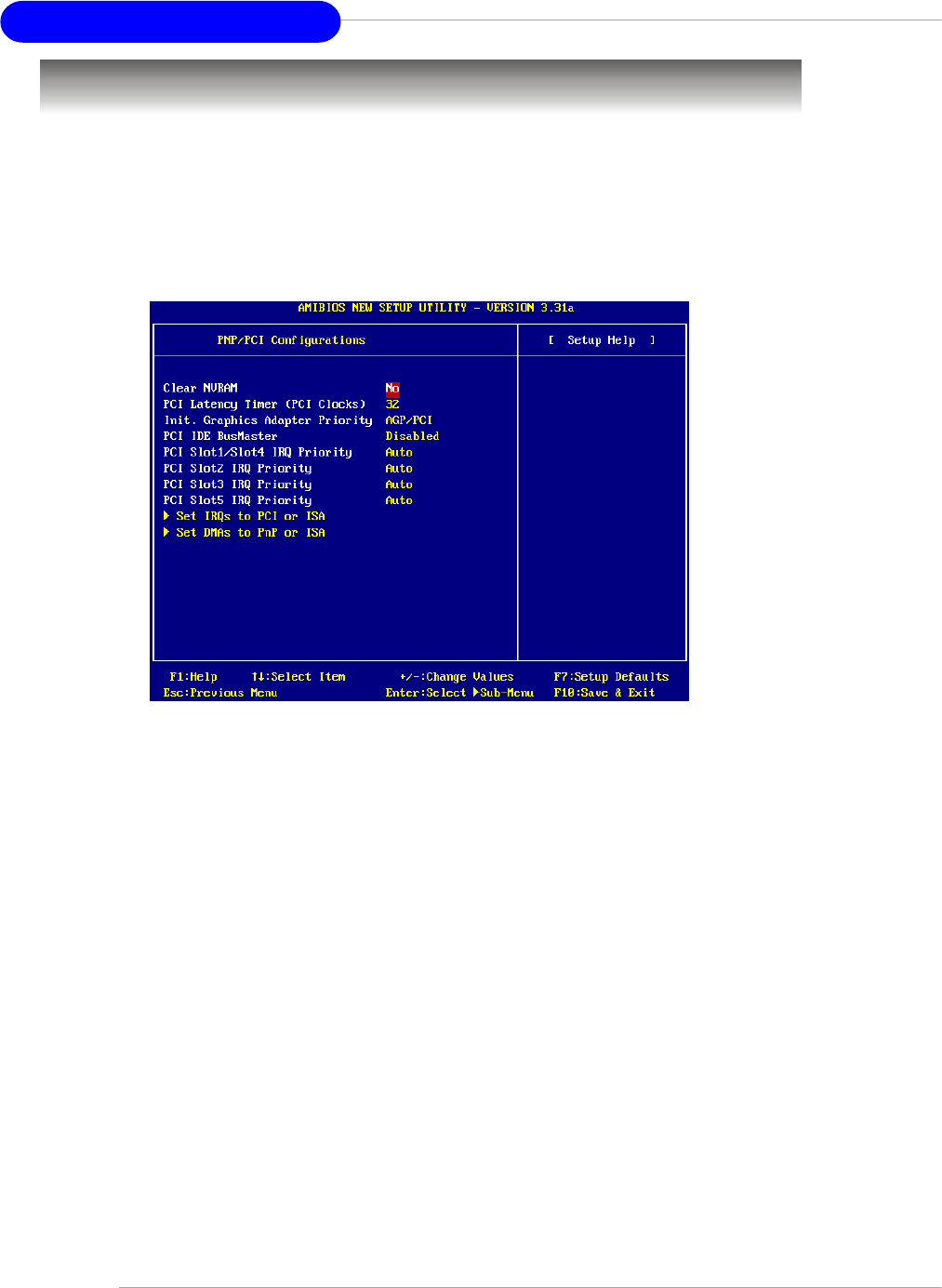
PNP/PCI Configurations
This section describes configuring the PCI bus system and PnP (Plug & Play)
feature. PCI, or Peripheral Component Interconnect, is a system which allows I/O
devices to operate at speeds nearing the speed the CPU itself uses when communi-
cating with its special components. This section covers some very technical items
and it is strongly recommended that only experienced users should make any changes
to the default settings.
Clear NVRAM
The ESCD (Extended System Configuration Data) NVRAM (Non-volatile Random Ac-
cess Memory) is where the BIOS stores resource information for both PNP and non-
PNP devices in a bit string format. When the item is set to [Yes], the system will reset
ESCD NVRAM right after the system is booted up and then set the setting of the item
back to [No] automatically.
PCI Latency Timer (PCI Clocks)
This item controls how long each PCI device can hold the bus before another takes
over. When set to higher values, every PCI device can conduct transactions for a
longer time and thus improve the effective PCI bandwidth. For better PCI performance,
you should set the item to higher values. Settings range from [32] to [248] at a 32
increment.
Init. Graphics Adapter Priority
This setting specifies which VGA card is your primary graphics adapter. Setting
options are:
[Internal VGA] The system initializes the onboard VGA device.
[AGP/Int-VGA] The system initializes the installed AGP card first. If an AGP card is
not available, it will initialize the onboard VGA device.
[AGP/PCI] The system initializes the installed AGP card first. If an AGP card is
not available, it will initialize the PCI VGA card.
3-17
BIOS Setup
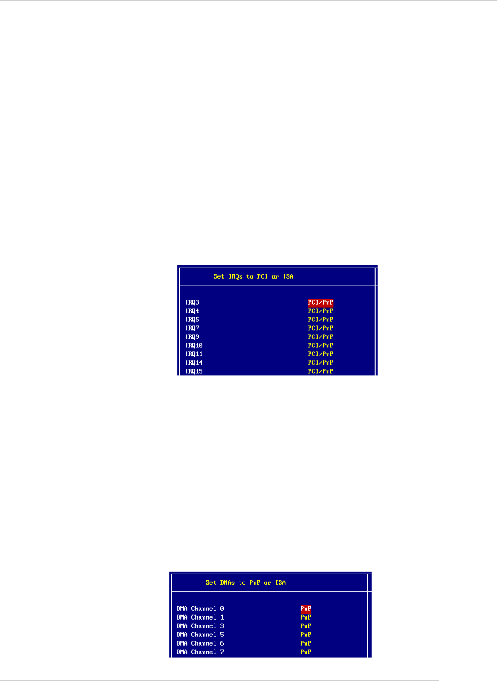
IRQ 3/4/5/7/9/10/11/14/15
These items specify the bus where the specified IRQ line is used.
The settings determine if AMIBIOS should remove an IRQ from the pool of
available IRQs passed to devices that are configurable by the system BIOS.
The available IRQ pool is determined by reading the ESCD NVRAM. If more IRQs
must be removed from the IRQ pool, the end user can use these settings to
reserve the IRQ by assigning an [ISA/EISA] setting to it. Onboard I/O is configured
by AMIBIOS. All IRQs used by onboard I/O are configured as PCI/PnP. If all IRQs
are set to [ISA/EISA], and IRQ 14/15 are allocated to the onboard PCI IDE, IRQ 9
will still be available for PCI and PnP devices. Available settings: [ISA/EISA] and
[PCI/PnP].
Set DMAs to PnP or ISA
Press <Enter> to enter the sub-menu and the following screen appears:
[PCI/AGP] The system initializes the installed PCI VGA card first. If a PCI VGA
card is not available, it will initialize the AGP card.
[PCI/Int-VGA] The system initializes the installed PCI VGA card first. If a PCI VGA
card is not available, it will initialize the onboard VGA device.
PCI IDE BusMaster
Set this option to [Enabled] to specify that the IDE controller on the PCI local bus has
bus mastering capability. Setting options: [Disabled], [Enabled].
PCI Slot1/Slot4 IRQ Priority, PCI Slot2 IRQ Priority, PCI Slot3 IRQ Priority, PCI
Slot5 IRQ Priority
These items specify the IRQ line for each PCI slot. Setting options: [3], [4], [5], [7], [9],
[10], [11], [Auto]. Selecting [Auto] allows BIOS to automatically determine the IRQ line
for each PCI slot.
Set IRQs to PCI or ISA
Press <Enter> to enter the sub-menu and the following screen appears:

3-18
MS-6788 ATX Mainboard
DMA Channel 0/1/3/5/6/7
These items specify the bus that the system DMA (Direct Memory Access)
channel is used.
The settings determine if AMIBIOS should remove a DMA from the available
DMAs passed to devices that are configurable by the system BIOS. The avail-
able DMA pool is determined by reading the ESCD NVRAM. If more DMAs must
be removed from the pool, the end user can reserve the DMA by assigning an
[ISA/EISA] setting to it.
3-19
BIOS Setup
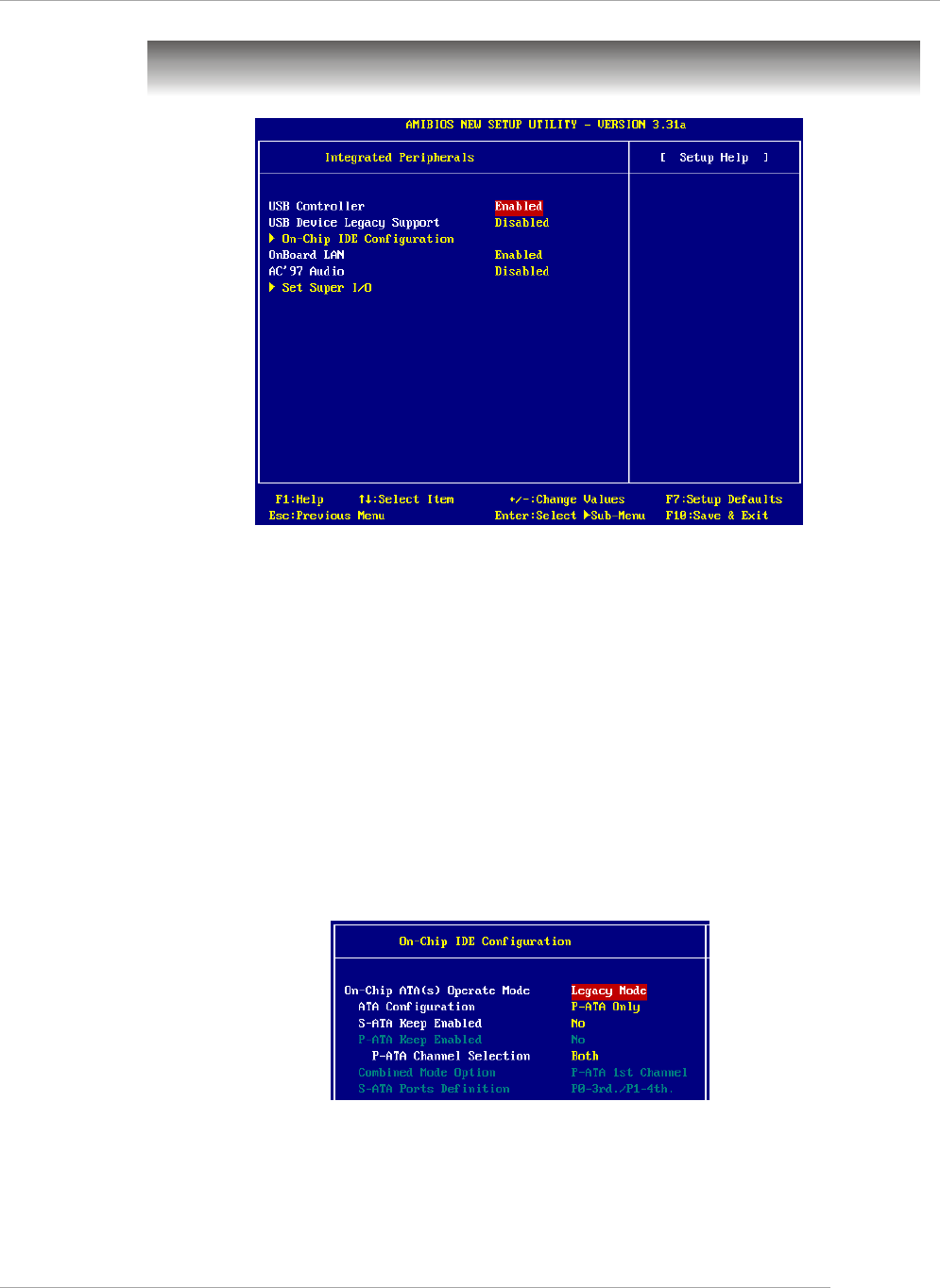
On-Chip ATA(s) Operate Mode
This setting allows you to determine how the RAID controller on the south
bridge is going to switch to SATA controller. [Legacy Mode] means you may use
the traditional 14 and 15 IRQs, while [Native Mode] means you may use all the
available IRQs. Setting options: [Legacy Mode], [Native Mode].
Integrated Peripherals
Please note that the options showed on your BIOS might be different de-
pending on the motherboard you buy.
USB Controller
This setting is used to enable/disable the onboard USB controllers. Setting options:
[Disabled], [Enabled].
USB Device Legacy Support
Set to [Enabled] if your need to use any USB 1.1/2.0 device in the operating system
that does not support or have any USB 1.1/2.0 driver installed, such as DOS and SCO
Unix. Set to [Disabled] only if you want to use any USB device other than the USB
mouse. Setting options: [Disabled], [Enabled].
On-Chip IDE Configuration
Press <Enter> to enter the sub-menu and the following screen appears:
3-20
MS-6788 ATX Mainboard
ATA Configuration
The field lets you configure the available ATA controller. Setting options:
[Disabled], [P-ATA Only], [S-ATA Only], [P-ATA+S-ATA].
S-ATA Keep Enabled
This item is available for you to enable/disable the onboard S-ATA. Setting
options: [Yes], [No].
P-ATA Keep Enabled
This item is available for you to enable/disable the onboard P-ATA. Setting
options: [Yes], [No].
P-ATA Channel Selection
This item is available for you to select the parallel ATA channel. Setting
options: [Primary], [Secondary], [Both].
Combined Mode Option
This item is available for you to select the combined mode of the ATA controllers.
Setting options: [P-ATA 1st Channel], [S-ATA 1st Channel].
S-ATA Ports Definition
This allows you to set the boot sequence of serial ATA ports.
MSI Reminds You...
If you wish to use S-ATA devices on your mainboard while the ATA
devices connected to the IDE1 and IDE2 are also available, you MUST
have Windows XP/2000 operation system in your computer, and con-
figure the settings listed as following when you enter the BIOS setup
program.
However, if you are using Windows 98/Me, please also refer to the
following settings for the best performance.
On-Chip IDE Configuration Settings in Windows XP/2000
(Maximum of 6 devices)
Settings in Windows 98/ME
(Maximum of 4 devices)
On-Chip ATA(s) Operate Mode Legacy Mode (not available)
ATA Configuration P-ATA Only P-ATA+S-ATA
S-ATA Keep Enabled Yes (not available)
P-ATA Keep Enabled (not available) (not available)
P-ATA Channel Selection Both (not available)
Combined Mode Option (not available) * S-ATA 1st Channel /
P-ATA 1st Channel
S-ATA Ports Definition P0-3rd. / P1-4th. P0-Master / P1-Slave
* When choosing S-ATA 1st Channel, you can use SATA1 & SATA2, IDE2.
When choosing P-ATA 1st Channel, you can use IDE1, SATA1 & SATA2.
3-21
BIOS Setup
OnBoard LAN
This setting controls the onboard LAN controller. Setting options: [Disabled], [Enabled].
AC’97 Audio
This item is used to enable or disable the onboard AC’97 (Audio Codec’97) feature.
Selecting [Auto] allows the mainboard to detect whether an audio device is used. If
an audio device is detected, the onboard AC’97 controller will be enabled; if not, the
controller is disabled. Disable the function if you want to use other controller cards to
connect an audio device. Settings: [Disabled] and [Auto].
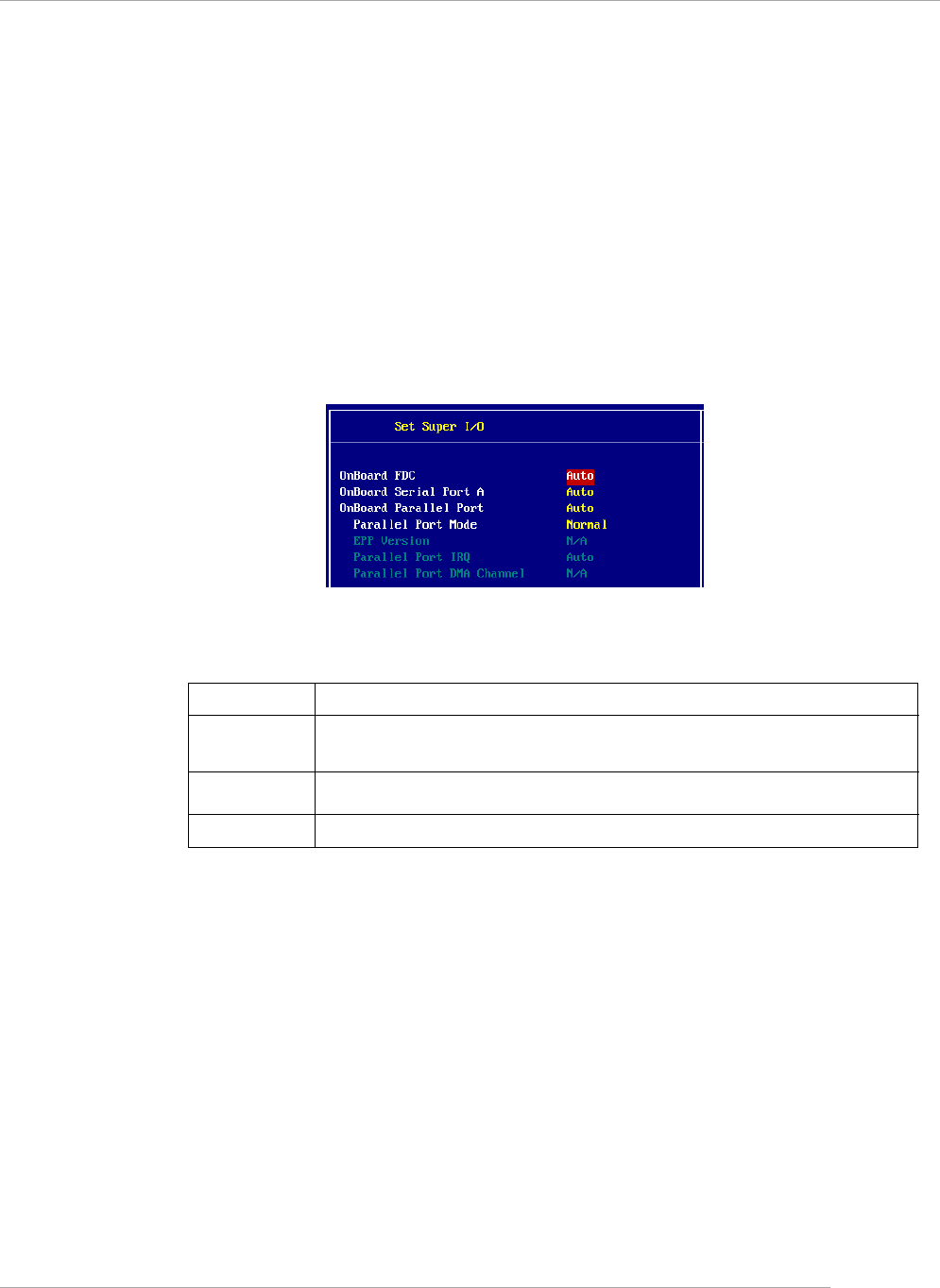
Set Super I/O
Press <Enter> to enter the sub-menu and the following screen appears:
OnBoard FDC
Select [Enabled] if your system has a floppy disk controller (FDD) installed on
the system board and you wish to use it.
Onboard Serial Port A
This item specifies the base I/O port addresses of the onboard Serial Port 1
(COM A). Selecting [Auto] allows AMIBIOS to automatically determine the cor-
rect base I/O port address. Settings: [Auto], [3F8/COM1], [2F8/COM2], [3E8/
COM3], [2E8/COM4] and [Disabled].
Onboard Parallel Port
This field specifies the base I/O port address of the onboard parallel port.
Selecting [Auto] allows AMIBIOS to automatically determine the correct base I/O
port address. Settings: [Auto], [378], [278], [3BC] and [Disabled].
Parallel Port Mode
This item selects the operation mode for the onboard parallel port: [ECP], [Normal],
[Bi-Dir] or [EPP].
Option Description
[Auto] BIOS will automatically determine whether to enable the
onboard Floppy controller or not.
[Enabled] Enables the onboard Floppy controller.
[Disabled] Disables the onboard Floppy controller.

3-22
MS-6788 ATX Mainboard
EPP Version
The item selects the EPP version used by the parallel port if the port is set
to EPP mode. Settings: [1.7] and [1.9].
Parallel Port IRQ
When Onboard Parallel Port is set to [Auto], the item shows [Auto]
indicating that BIOS determines the IRQ for the parallel port automatically.
Parallel Port DMA Channel
When Parallel Port Mode is set to [Auto], the field will show [Auto]
indicating that BIOS automatically determines the DMA channel for the par-
allel port.
3-23
BIOS Setup
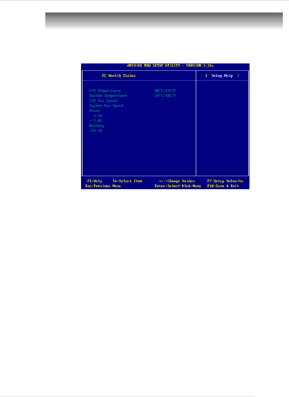
PC Health Status
This section shows the status of your CPU, fan, overall system status, etc.
Monitor function is available only if there is hardware monitoring mechanism onboard.
CPU/System Temperature, CPU/System Fan Speed, Vcore, 3.3V, +5.0V,
Battery, +5V SB
These items display the current status of all of the monitored hardware devices/
components such as CPU voltages, temperatures and all fans’ speeds.
3-24
MS-6788 ATX Mainboard
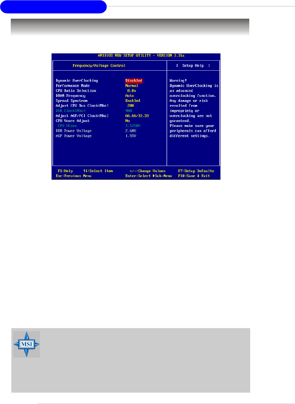
Use this menu to specify your settings for frequency/voltage control.
Frequency/Voltage Control
Dynamic OverClocking
Dynamic Overclocking Technology is the automatic overclocking function, included in
the MSITM’s newly developed CoreCellTM Technology. It is designed to detect the load
balance of CPU while running programs, and to adjust the best CPU frequency
automatically. When the motherboard detects CPU is running programs, it will speed
up CPU automatically to make the program run smoothly and faster. When the CPU is
temporarily suspending or staying in the low load balance, it will restore the default
settings instead. Usually the Dynamic Overclocking Technology will be powered only
when users' PC need to run huge amount of data like 3D games or the video process,
and the CPU frequency need to be boosted up to enhance the overall performance.
Setting options:
[Disabled] Disable Dynamic Overclocking.
[Private] 1st level of overclocking.
[Sergeant] 2nd level of overclocking.
[Captain] 3rd level of overclocking, also the default value of Load
High Performance Defaults.
[Colonel] 4th level of overclocking.
[General] 5th level of overclocking.
[Commander] 6th level of overclocking.
MSI Reminds You...
Even though the Dynamic Overclocking Technology is more stable
than manual overclocking, basically, it is still risky. We suggest user
to make sure that your CPU can afford to overclocking regularly first.
If you find the PC appears to be unstable or reboot incidentally, it's
better to disable the Dynamic Overclocking or to lower the level of
overclocking options. By the way, if you need to conduct overclocking
manually, you also need to disable the Dynamic OverClocking first.

3-25
BIOS Setup
Performance Mode
This item allows you to control the MAT (memory acceleration technology) function of
CPU. MAT is MSITM’s exclusive technology, specializing in optimizing the data transfer
rate among CPU, north bridge chip and memory, and also in procuring better memory
performance and bandwidth up to 10%. Selecting [Fast] will enable MAT. Please be
noted that not every memory is compatible with MAT. If the system fail to reboot for
four times, the BIOS will be restored to the Default value ([Normal]). Setting options:
[Normal], [Fast].
CPU Ratio Selection
This setting controls the multiplier that is used to determine the internal clock speed of
the processor relative to the external or motherboard clock speed.
DRAM Frequency
Use this field to configure the clock frequency of the installed DRAM. Settings are:
PSB 400: [100-355MHz]
PSB 533: [133-500MHz]
PSB 800: [200-500MHz]
Spread Spectrum
When the motherboard’s clock generator pulses, the extreme values (spikes) of the
pulses creates EMI (Electromagnetic Interference). The Spread Spectrum function
reduces the EMI generated by modulating the pulses so that the spikes of the pulses
are reduced to flatter curves. If you do not have any EMI problem, leave the setting at
[Disabled] for optimal system stability and performance. But if you are plagued by EMI,
activate the Spread Spectrum for EMI reduction. Remember to disable Spread
Spectrum if you are overclocking because even a slight jitter can introduce a tempo-
rary boost in clock speed which may just cause your overclocked processor to lock
up. Options: [Disabled], [Enabled].
MSI Reminds You...
1. Even though MAT is easy to use, it doesn't mean there's no risk at
all. We recommend you to check if your memory is able to bear
MAT setting or not before deciding to always use it. If your system
will be unstable or reboot incidentally after switching to [Fast],
please switch back to [Normal]. Moreover, if you want to conduct
FSB overclocking, you should set MAT as [Normal].
2. Meanwhile, for security reason, there are two functions to protect
BIOS and protect user’s system from crashing:
(a) There is a safe hotkey "Ins" in BIOS. If the overclocking or/and
MAT fails to run, you can press "Ins" key while rebooting system to
restore to the BIOS Defaults.
(b) If your system reboot for four times continually, the BIOS will be
restored to the Defaults ([Normal]), too

3-26
MS-6788 ATX Mainboard
Adjust CPU Bus Clock (Mhz)
This item allows you to select the CPU Bus clock frequency (in MHz) and overclock
the processor by adjusting the FSB clock to a higher frequency. Also the setting you
choose will change color for warning if the value is of over the specifications.
DDR Clock (Mhz)
This read-only item allows you to view the current DDR clock.
Adjust AGP/PCI Clock (Mhz)
This item allows you to select the AGP/PCI clock frequency (in MHz) by adjusting the
AGP/PCI clock to a higher frequency.
CPU Vcore Adjust
The setting allows you to adjust the CPU Vcore voltage. Available options: [Yes], [No].
CPU Vcore
The setting is adjustable if you set the CPU Vcore Adjust to [Yes] .
DDR Power Voltage
Adjusting the DDR voltage can increase the DDR speed. Any changes made to this
setting may cause a stability issue, so changing the DDR voltage for long-term
purpose is NOT recommended.
AGP Power Voltage
AGP voltage is adjustable in the field, allowing you to increase the performance of
your AGP display card when overclocking, but the stability may be affected.
MSI Reminds You...
The settings shown in different color in CPU Vcore (V), DDR Power
Voltage (V) and AGP Power Voltage (V) helps to verify if your setting
is proper for your system.
White: Safe setting.
Yellow: High performance setting.
Red: Not recommended setting and the system may be unstable.
MSI Reminds You...
Changing CPU Ratio/Vcore could result in the instability of the system;
therefore, it is NOT recommended to change the default setting for
long-term usage.

3-27
BIOS Setup
Set Supervisor/User Password
When you select this function, a message as below will appear on the screen:
Type the password, up to six characters in length, and press <Enter>. The
password typed now will replace any previously set password from CMOS memory.
You will be prompted to confirm the password. Retype the password and press
<Enter>. You may also press <Esc> to abort the selection and not enter a password.
To clear a set password, just press <Enter> when you are prompted to enter
the password. A message will show up confirming the password will be disabled.
Once the password is disabled, the system will boot and you can enter Setup
without entering any password.
When a password has been set, you will be prompted to enter it every time
you try to enter Setup. This prevents an unauthorized person from changing any part
of your system configuration.
Additionally, when a password is enabled, you can also have AMIBIOS to
request a password each time the system is booted. This would prevent unautho-
rized use of your computer. The setting to determine when the password prompt is
required is the PASSWORD CHECK option of the ADVANCED BIOS FEATURES menu.
If the PASSWORD CHECK option is set to Always, the password is required both at
boot and at entry to Setup. If set to Setup, password prompt only occurs when you
try to enter Setup.
MSI Reminds You...
About Supervisor Password & User Password:
Supervisor password: Can enter and change the settings of
thesetup menu.
User password: Can only enter but do not have the right to
change the settings of the setup menu.
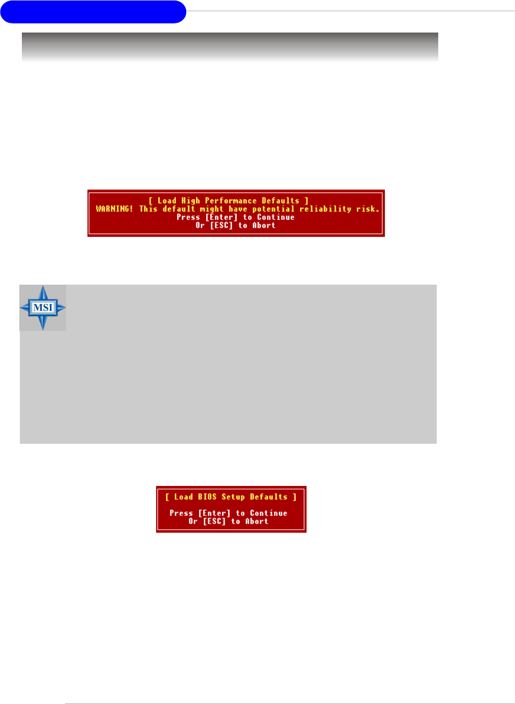
3-28
MS-6788 ATX Mainboard
Load High Performance/BIOS Setup Defaults
The two options on the main menu allow users to restore all of the BIOS
settings to High Performance defaults or BIOS Setup defaults. The High Performance
Defaults are the values set by the mainboard manufacturer for the best system
performance but probably will cause a stability issue. The BIOS Setup Defaults are
the default values also set by the mainboard manufacturer for stable performance of
the mainboard.
When you select Load High Performance Defaults, a message as below
appears:
Pressing <Enter> loads the default BIOS values that enable the best system
performance but may lead to a stability issue.
When you select Load BIOS Setup Defaults, a message as below appears:
Pressing <Enter> loads the default values that are factory settings for stable
system performance.
MSI Reminds You...
The option is for power or overclocking users only. Use of high
performance defaults will tighten most timings to increase the system
performance. Therefore, a high-end system configuration is a must,
which means you need high-quality VGA adapter, RAM and so on. We
don’t recommend that users should apply the high performance
defaults in their regular systems. Otherwise, the system may be-
come unstable or even crash. If the system crashes or hangs after
enabling the feature, please CLEAR CMOS DATA to resolve the
problem. For more information, refer to “Clear CMOS Jumper:JBAT1”
in Chapter 2.
