Msi K8N Neo4 F Motherboard Atx Users Manual ManualsLib Makes It Easy To Find Manuals Online!
2014-12-11
: Msi Msi-K8N-Neo4-F-Motherboard-Atx-Users-Manual-120721 msi-k8n-neo4-f-motherboard-atx-users-manual-120721 msi pdf
Open the PDF directly: View PDF ![]() .
.
Page Count: 92
i
English / French / German
Version
G52-M7125X6
MS-7125 (v1.X) ATX Mainboard
K8N Neo4 Series
ii
Manual Rev: 1.0
Release Date: February 2005
FCC-B Radio Frequency Interference Statement
This equipment has been tested and found to comply with the limits for a class B
digital device, pursuant to part 15 of the FCC rules. These limits are designed to
provide reasonable protection against harmful interference when the equipment is
operated in a commercial environment. This equipment generates, uses and can
radiate radio frequency energy and, if not installed and used in accordance with the
instruction manual, may cause harmful interference to radio communications. Operation
of this equipment in a residential area is likely to cause harmful interference, in which
case the user will be required to correct the interference at his own expense.
Notice 1
The changes or modifications not expressly approved by the party responsible for
compliance could void the user’s authority to operate the equipment.
Notice 2
Shielded interface cables and A.C. power cord, if any, must be used in order to
comply with the emission limits.
VOIR LA NOTICE D’INSTALLATION AVANT DE RACCORDER AU RESEAU.
Micro-Star International
MS-7125
This device complies with Part 15 of the FCC Rules. Operation is subject to the
following two conditions:
(1) this device may not cause harmful interference, and
(2) this device must accept any interference received, including interference that
may cause undesired operation

iii
Copyright Notice
The material in this document is the intellectual property of MICRO-STAR
INTERNATIONAL. We take every care in the preparation of this document, but no
guarantee is given as to the correctness of its contents. Our products are under
continual improvement and we reserve the right to make changes without notice.
Trademarks
All trademarks are the properties of their respective owners.
AMD, Athlon™, Athlon™ XP, Thoroughbred™, and Duron™ are registered
trademarks of AMD Corporation.
Intel® and Pentium® are registered trademarks of Intel Corporation.
PS/2 and OS®/2 are registered trademarks of International Business Machines
Corporation.
Microsoft is a registered trademark of Microsoft Corporation. Windows® 98/2000/NT/
XP are registered trademarks of Microsoft Corporation.
NVIDIA, the NVIDIA logo, DualNet, and nForce are registered trademarks or trade-
marks of NVIDIA Corporation in the United States and/or other countries.
Netware® is a registered trademark of Novell, Inc.
Award® is a registered trademark of Phoenix Technologies Ltd.
AMI® is a registered trademark of American Megatrends Inc.
Kensington and MicroSaver are registered trademarks of the Kensington Technology
Group.
PCMCIA and CardBus are registered trademarks of the Personal Computer Memory
Card International Association.
Revision History
Revision Revision History Date
V1.0 First release of PCB 1.0 December 2004
with nVIDIA nForce4 Ultra
V1.0 First release for PCB 1.0 February 2005
with nVIDIA nForce4 Ultra
For European manuals

iv
1. Always read the safety instructions carefully.
2. Keep this User’s Manual for future reference.
3. Keep this equipment away from humidity.
4. Lay this equipment on a reliable flat surface before setting it up.
5. The openings on the enclosure are for air convection hence protects the equip-
ment from overheating. Do not cover the openings.
6. Make sure the voltage of the power source and adjust properly 110/220V be-
fore connecting the equipment to the power inlet.
7. Place the power cord such a way that people can not step on it. Do not place
anything over the power cord.
8. Always Unplug the Power Cord before inserting any add-on card or module.
9. All cautions and warnings on the equipment should be noted.
10. Never pour any liquid into the opening that could damage or cause electrical
shock.
11. If any of the following situations arises, get the equipment checked by a service
personnel:
hThe power cord or plug is damaged.
hLiquid has penetrated into the equipment.
hThe equipment has been exposed to moisture.
hThe equipment has not work well or you can not get it work according to
User’s Manual.
hThe equipment has dropped and damaged.
hThe equipment has obvious sign of breakage.
12. Do not leave this equipment in an environment unconditioned, storage
temperature above 600 C (1400F), it may damage the equipment.
Technical Support
If a problem arises with your system and no solution can be obtained from the user’s
manual, please contact your place of purchase or local distributor. Alternatively,
please try the following help resources for further guidance.
h Visit the MSI homepage & FAQ site for technical guide, BIOS updates, driver
updates, and other information: http://www.msi.com.tw & http://www.msi.
com.tw/program/service/faq/faq/esc_faq_list.php
h Contact our technical staff at: support@msi.com.tw
Safety Instructions
CAUTION: Danger of explosion if battery is incorrectly replaced.
Replace only with the same or equivalent type recommended by the
manufacturer.
v
CONTENTS
FCC-B Radio Frequency Interference Statement ........................................................ ii
Copyright Notice ........................................................................................................... iii
Revision History ............................................................................................................ iii
Technical Support ........................................................................................................ iv
Safety Instructions ...................................................................................................... iv
English .................................................................................................................. E-1-1
1. Getting Started ........................................................................................... E-1-3
2. Hardware Setup ........................................................................................ E-2-1
3. BIOS Setup ................................................................................................. E-3-1
Français .................................................................................................................... F-1
Guide d’Utilisation ................................................................................................ F-3
Deutsch ................................................................................................................... G-1
Benutzerhandbuch............................................................................................. G-3

E-1-1
Getting Started
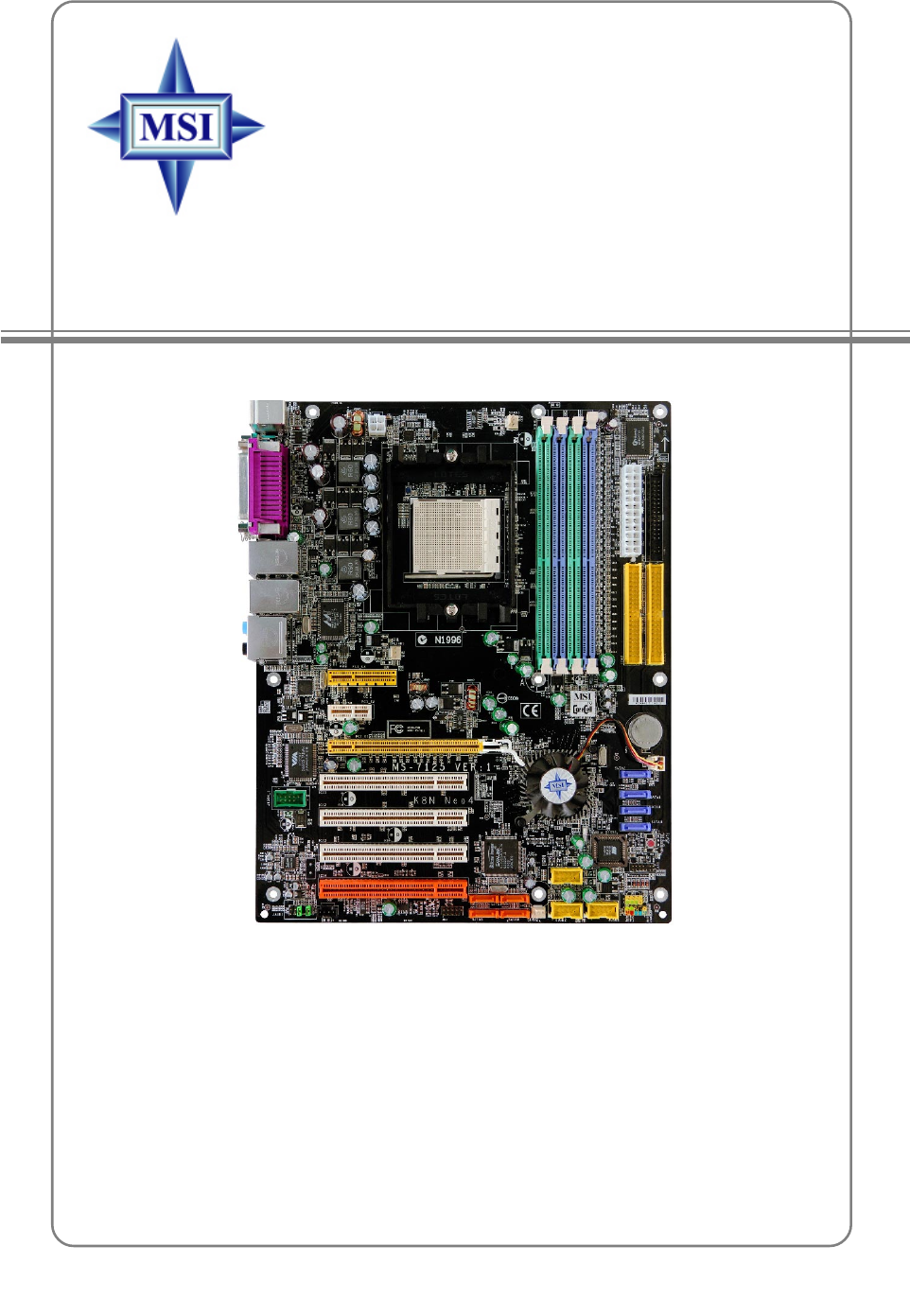
K8N Neo4 Platinum
(MS-7125 v1.X)
ATX mainboard.
English
E-1-1

E-1-2
MS-7125 M-ATX Mainboard

E-1-3
Getting Started
Chapter 1. Getting
Started
Getting Started
Thank you for choosing the K8N Neo4 Platinum (MS-7125)
v1.X ATX mainboard. The K8N Neo4 Platinum mainboard is based
on nVIDIA® nForce™4 Ultra chipset for optimal system efficiency.
Designed to fit the advanced AMD® K8 Athlon 64 FX / Athlon 64
processor, the K8N Neo4 Platinum mainboard delivers a high per-
formance and professional desktop platform solution.

E-1-4
MS-7125 M-ATX Mainboard
Mainboard Specifications
CPU
hSupports Socket-939 for AMD K8 Athlon 64 FX / Athlon 64 (Socket939) processor
hSupports up to Athlon64 3500+, 3800+, or higher CPU
(For the latest information about CPU, please visit http://www.msi.com.tw/program/
products/mainboard/mbd/pro_mbd_cpu_support.php)
Chipset
hnVIDIA nForce4 Ultra
- HyperTransport link to the AMD Athlon 64/Athlon 64 FX CPU
- HyperTransport supporting speed up to 1GHz (2000MT/s)
- Supports PCI Express x16/x1/x2 interface
- Two independent SATA controllers, for four drives
- Dual Fast ATA-133 IDE controllers
- IEEE802.3 nVIDIA MAC for 1000BASE-T
Main Memory
hSupports dual channel, eight memory banks DDR 266/333/400, using four 184-
pin DDR DIMMs
hSupports a maximum memory size up to 4GB
hSupports 2.5v DDR SDRAM DIMM
(For the updated supporting memory modules, please visit http://www.msi.com.tw/
program/products/mainboard/mbd/pro_mbd_trp_list.php.)
Slots
hOne PCI Express x16 slot (supports PCI Express Bus specification v1.0a
compliant)
hOne PCI Express x1 slots (supports PCI Express Bus specification v1.0a
compliant)
hOne PCI Express x4 slots (supports PCI Express x2 device only )
hFour 32-bit Master PCI Bus slots, includes one orange slot which is reserved as
a communication slot.
hSupport 3.3V/5V PCI bus Interface
On-Board IDE
hAn IDE controller on the nVIDIA® nForce4 Ultra chipset provides IDE HDD/CD-
ROM with PIO, Bus Master and Ultra DMA 66/100/133 operation modes
hCan connect up to 4 IDE devices
On-Board SATA
hNV RAID supports 4 SATA ports(SATA1-4). SATAII Transfer rate is up to
300MB/s.
hSilicon Image’s SATARAID5TM supports another 4 SATA ports(SATA5-8). SATA
Transfer rate is up to 150MB/s. (Optional)

E-1-5
Getting Started
USB Interface
h10 USB ports
- Controlled by nForce4 Ultra chipset
- 4 ports in the rear I/O, 6 ports via the external bracket
NV RAID (Software)
hSupports up to 4 SATA and 4 ATA133 Hard drives
- RAID 0 or 1, 0+1, JBOD is supported
- RAID function available for PATA+SATA H/D drives
Silicon Image’s SATARAID5TM (Software) (Optional)
hRAID 0 or 1, RAID5, RAID10, and JBOD groups are supported
hSupport up to 4 SATA devices connected to a single controller
Dual LAN (Optional)
hSupports dual LAN jacks
- 1st LAN supports 10/100/1000 Fast Ethernet by Marvell 88E1111
- 2nd LAN supports 10/100/1000 Fast Ethernet by Marvell 88E8053
IEEE 1394 (Optional)
hSupports up to two 1394 ports (rear panel x 1, pinheader x 1). Transfer rate is
up to 400Mbps
Audio
hChip integrated by Realtek ALC850
- Direct Sound AC97 audio
- 7.1 Channel output
On-Board Peripherals
hOn-Board Peripherals include:
- 1 floppy port supports 1 FDD with 360K, 720K, 1.2M, 1.44M and 2.88Mbytes
- 1 serial port
- 1 parallel port supporting SPP/EPP/ECP mode
- 1 Audio jack(5-in-1), coaxial/fiber SPDIF out
- 1 IrDA pinheader
- 1 CD-In pinheader
- 1 D-Bracket2 pinheader
- 2 IEEE1394 ports (Rear * 1 / Front * 1)(Optional)
- 10 USB1.1/2.0 ports (Rear * 4 / Front * 6)

E-1-6
MS-7125 M-ATX Mainboard
BIOS
hThe mainboard BIOS provides “Plug & Play” BIOS which detects the peripheral
devices and expansion cards of the board automatically.
hThe mainboard provides a Desktop Management Interface (DMI) function which
records your mainboard specifications.
hSupports boot from LAN, USB Device 1.1 & 2.0, and SATA HDD.
Dimension
hATX Form Factor (30.4 cm X 24.4 cm)
Mounting
h9 mounting holes
MSI Reminds You...
1. Now the nVidia nForce4 system driver is only available for Windows
2000 and Windows XP.
2. To create a bootable RAID volume for a Windows 2000 environment,
Microsoft’s Windows 2000 Service Pack 4 (SP4) is required. As the
end user cannot boot without SP4, a combination installation CD
must be created before attempting to install the operating system
onto the bootable RAID volume.
To create the combination installation CD, please refer to the follow-
ing website:
http://www.microsoft.com/windows2000/downloads/
servicepacks/sp4/HFdeploy.htm
E-1-7
Getting Started
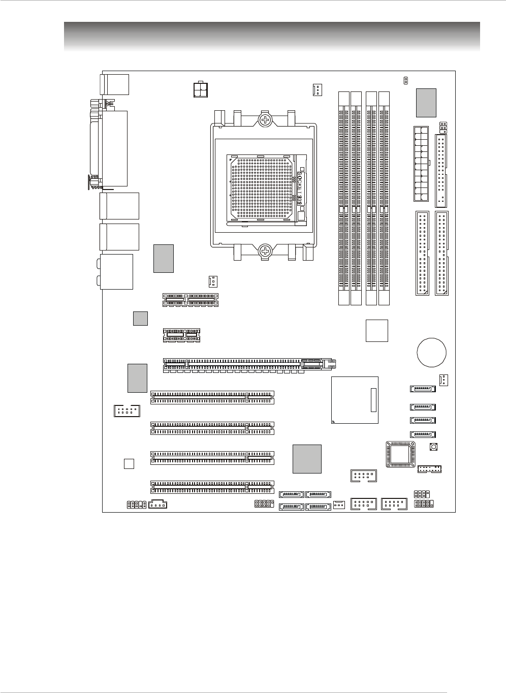
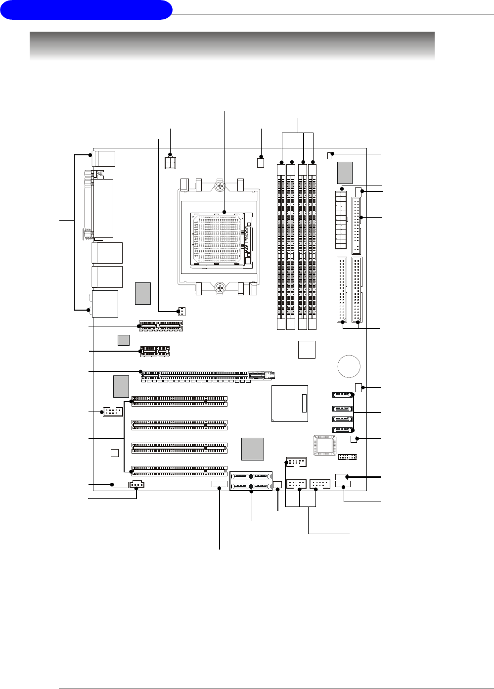
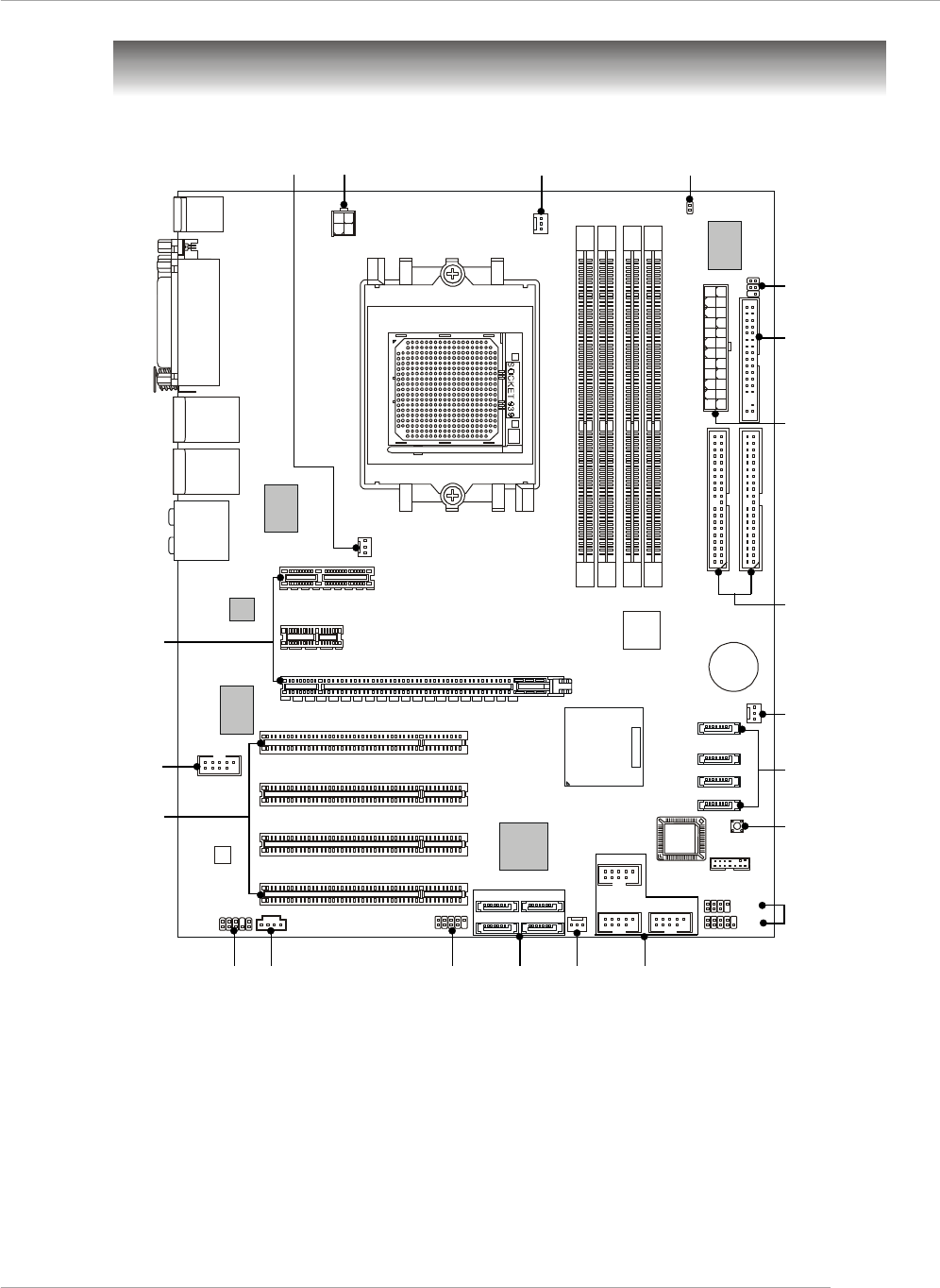
K8N Neo4 Platinum (MS-7125 v1.X) ATX Mainboard
CPUFAN1
NBFAN1
S1W
SFAN2
JPW1
FDD1
SATA3
SATA5 SATA8
SATA6 SATA7
SATA4
SATA1
SATA2
JCD1
T:
M:
B:
Line-In
Line-Out
Mic
T:RS -Out
M:CS
B:SPDIF Out
-Out
T: LAN j ac k
B: USB ports
(Optional)
T: LAN j ack
B: USB ports
(Optional)
Winbond
W83627THF
Silicon Image
SATALink
Sil3114CT176
(Optional)
VIA
VT6307
(Optional)
88E1111-RCJ
(Optional)
BATT
+
DIMM 1
SFAN1
DIMM 3
DIMM 2
DIMM 4
ATX1
PCI Slot 3
PCI Slot 2
PCI Slot 1
PCI _E3
PCI _E2
PCI _E1
IDE 2
IDE 1
JFP1
JDB1
JFP2
JIR1JIR1
JCI1
JLPC1
JAUD1 JUSB2 JUSB3
JUSB1
J1394_1
(Optional)
Top : Parallel Port
Bottom:
COM Port
1394 Port (Optional)
SPDIF OUT
Top : mouse
Bottom: keyboard
MSI
CoreCell
BIOS
Codec
PCI Slot 4
88E8053-NNC
(Optional)
NForce4
Ultra
(
Optional
)
Mainboard Layout
E-1-8
MS-7125 M-ATX Mainboard
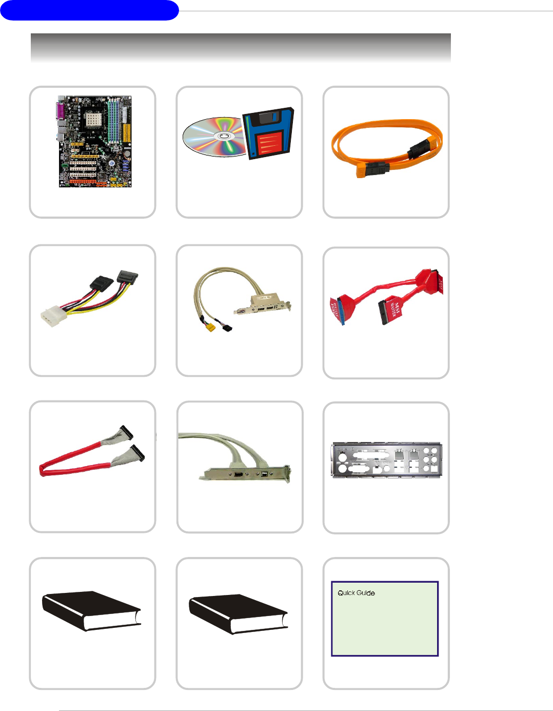
Packing Contents
Power Cable
SATA Cable (Optional)
User’s Guide Test Report
D-Bracket 2 (Optional)
MSI motherboard
MSI Driver/Utility CD
SATA RAID Driver
Diskette
Round Cable of
IDE Devices
Back IO Shield
Quick Guide
1394 Cable (Optional)
Round Cable of
Floppy Disk

Hardware Setup
E-2-1
Chapter 2. Hardware Setup
This chapter tells you how to install the CPU, memory modules,
and expansion cards, as well as how to setup the jumpers on the
mainboard. Also, it provides the instructions on connecting the periph-
eral devices, such as the mouse, keyboard, etc.
While doing the installation, be careful in holding the compo-
nents and follow the installation procedures.
Hardware Setup
MS-7125 M-ATX Mainboard
E-2-2
Quick Components Guide
DDR DIMMs, p.2-7
JDB1, p.2-22
JFP1, p.2-19
Back Panel
I/O, p.2-12
JPW1, p.2-10
IDE1/2, p.2-17
ATX1, p.2-10
JFP2, p.2-19
PCI_E2, p.2-26
PCI Slots 1~4,
p.2-26
JUSB1~3, p.2-19
SATA1~4,
p.2-18
J1394_1, p.2-21
(Optional)
NBFAN1,
p.2-16
CPUFAN1, p.2-16
JAUD1, p.2-20
SW1, p.2-25
FDD1, p.2-16
SFAN1, p.2-16
JCD1, p.2-18
JCI1, p.2-7
JIR1, p.2-20
SFAN2,
p.2-16
SATA5~8,
p.2-18
PCI_E1, p.2-26
PCI_E3, p.2-26
CPU, p.2-3

Hardware Setup
E-2-3
Central Processing Unit: CPU
The mainboard supports AMD® Athlon64 processor. The mainboard uses a CPU
socket called Socket-939 for easy CPU installation. When you are installing the CPU,
make sure the CPU has a heat sink and a cooling fan attached on the top to
prevent overheating. If you do not have the heat sink and cooling fan, contact your
dealer to purchase and install them before turning on the computer.
For the latest information about CPU, please visit http://www.msi.com.tw/program/
products/mainboard/mbd/pro_mbd_cpu_support.php.
MSI Reminds You...
Overheating
Overheating will seriously damage the CPU and system, always make
sure the cooling fan can work properly to protect the CPU from
overheating.
Replacing the CPU
While replacing the CPU, always turn off the ATX power supply or
unplug the power supply’s power cord from grounded outlet first to
ensure the safety of CPU.
Overclocking
This motherboard is designed to support overclocking. However, please
make sure your components are able to tolerate such abnormal setting,
while doing overclocking. Any attempt to operate beyond product speci-
fications is not recommended. We do not guarantee the damages
or risks caused by inadequate operation or beyond product
specifications.
MS-7125 M-ATX Mainboard
E-2-4
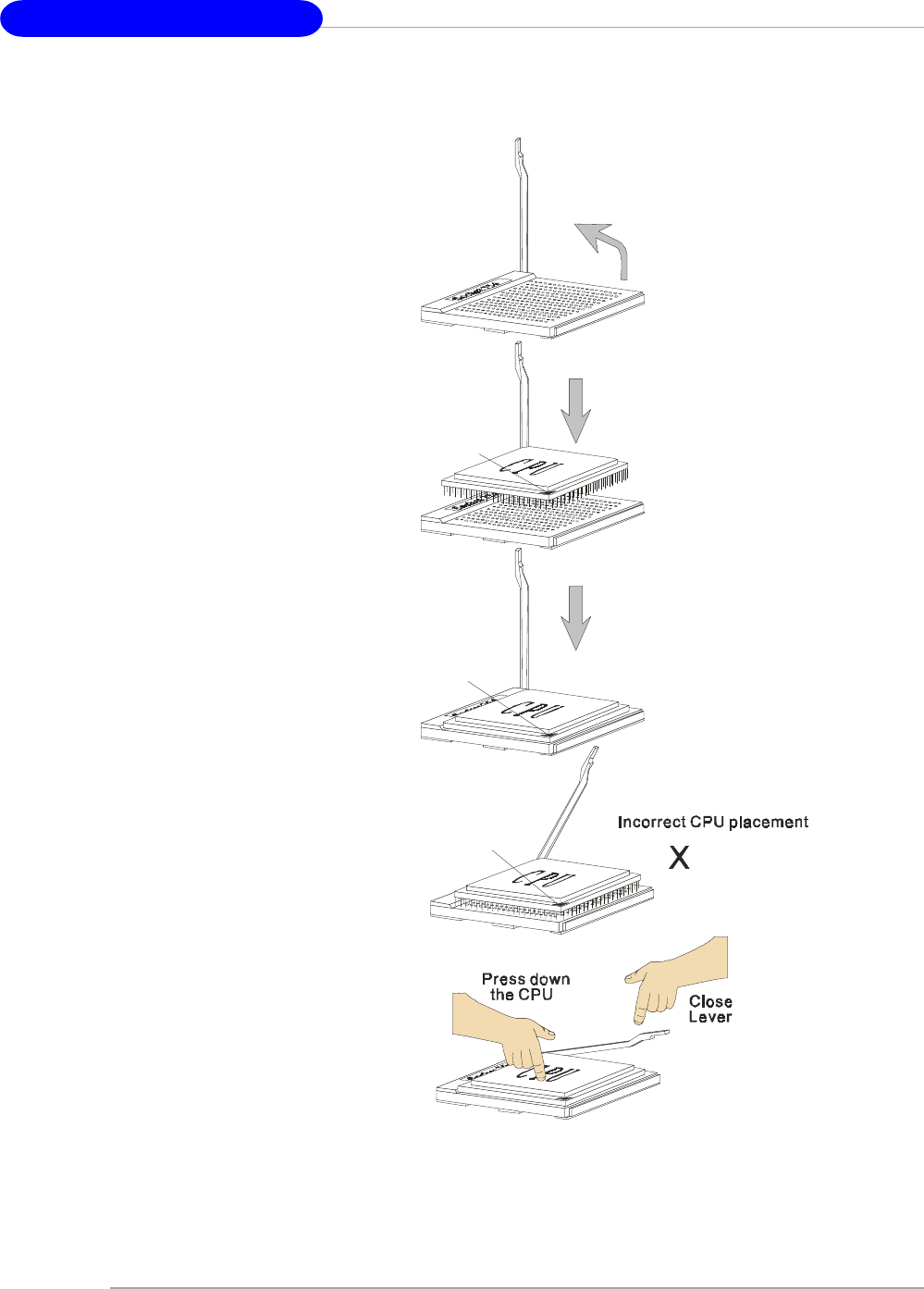
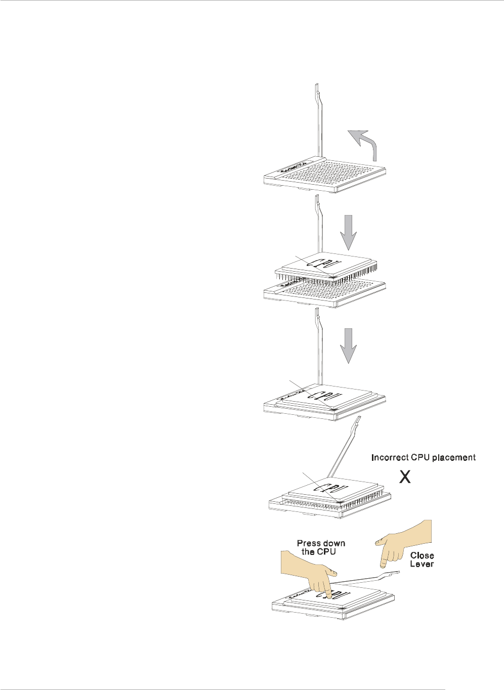
CPU Installation Procedures for Socket 939
1. Please turn off the power and
unplug the power cord before
installing the CPU.
2. Pull the lever sideways away
from the socket. Make sure to
raise the lever up to a 90-de-
gree angle.
3. Look for the gold arrow on the
CPU. The gold arrow should point
as shown in the picture. The CPU
can only fit in the correct
orientation.
4. If the CPU is correctly installed,
the pins should be completely
embedded into the socket and
can not be seen. Please note
that any violation of the correct
installation procedures may
cause permanent damages to
your mainboard.
5. Press the CPU down firmly into
the socket and close the lever.
As the CPU is likely to move while
the lever is being closed, al-
ways close the lever with your
fingers pressing tightly on top of
the CPU to make sure the CPU is
properly and completely embed-
ded into the socket.
Open Lever
90 degree
Sliding
Plate
Gold arrow
Gold arrow
Gold arrow
Correct CPU placement
O
Hardware Setup
E-2-5
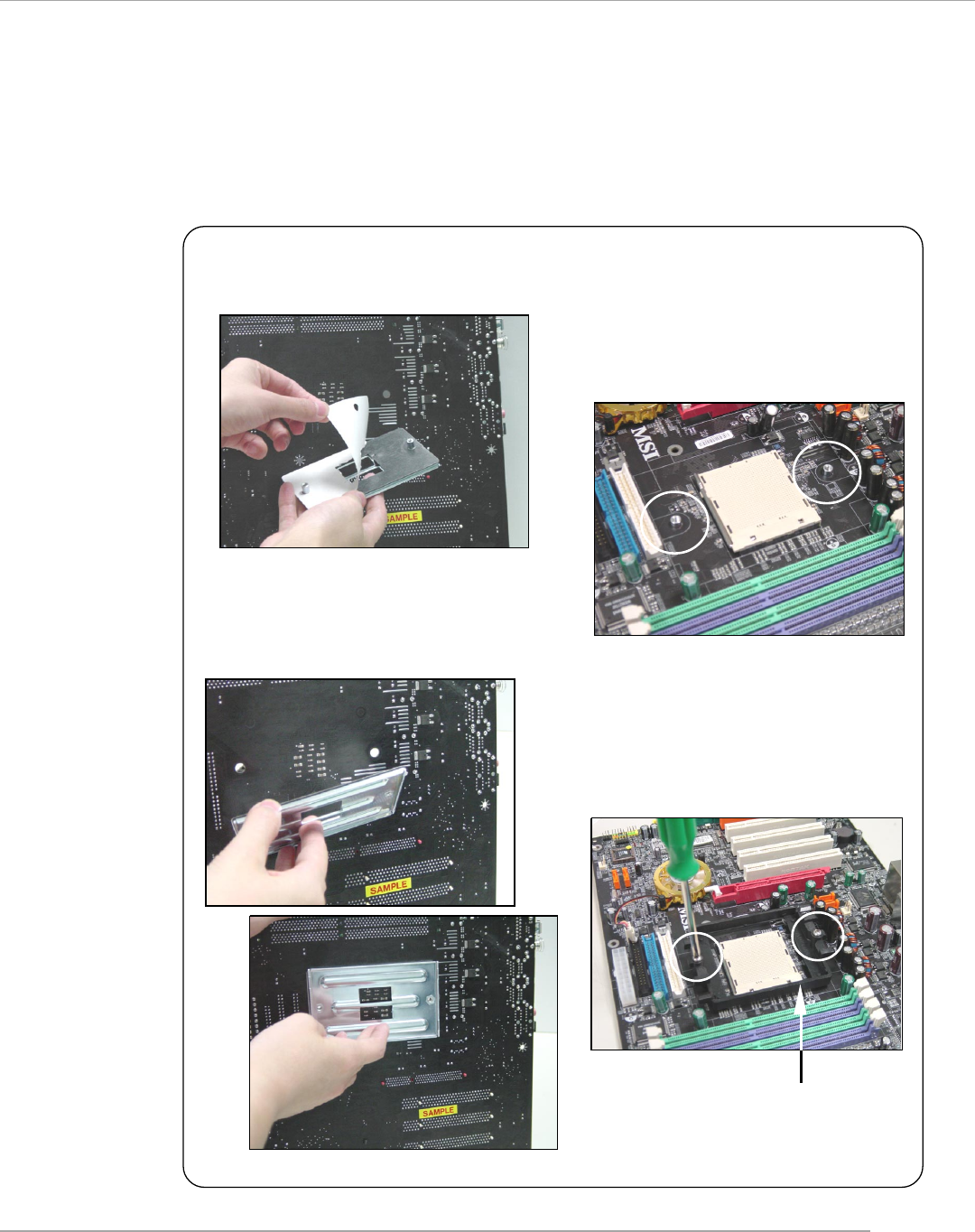
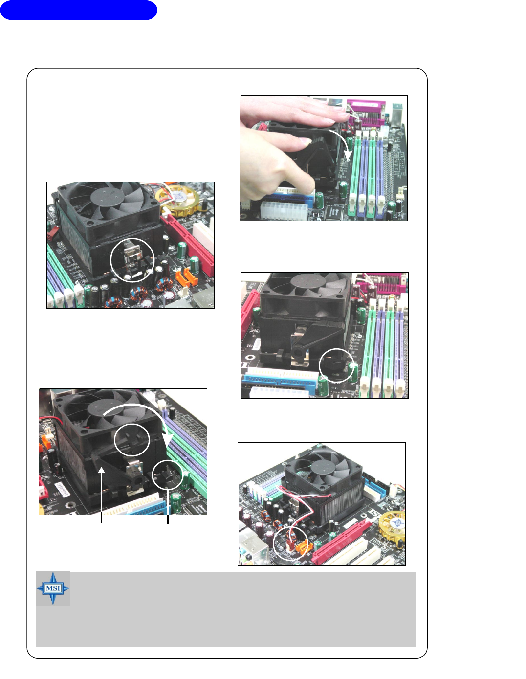
Installing AMD Athlon64 CPU Cooler Set
When you are installing the CPU, make sure the CPU has a heat sink and a
cooling fan attached on the top to prevent overheating. If you do not have the
heat sink and cooling fan, contact your dealer to purchase and install them before
turning on the computer.
1. Detach the shield of the backplate’s
paster.
2. Turn over the mainboard, and install
the backplate to the proper position.
3. Turn over the mainboard again, and
place the mainboard on the flat
surface.
Locate the two screw holes of the
mainboard.
4. Align the retention mechanism and
the backplate.
Fix the retention mechanism and the
backplate with two screws.
retention mechanism
MS-7125 M-ATX Mainboard
E-2-6
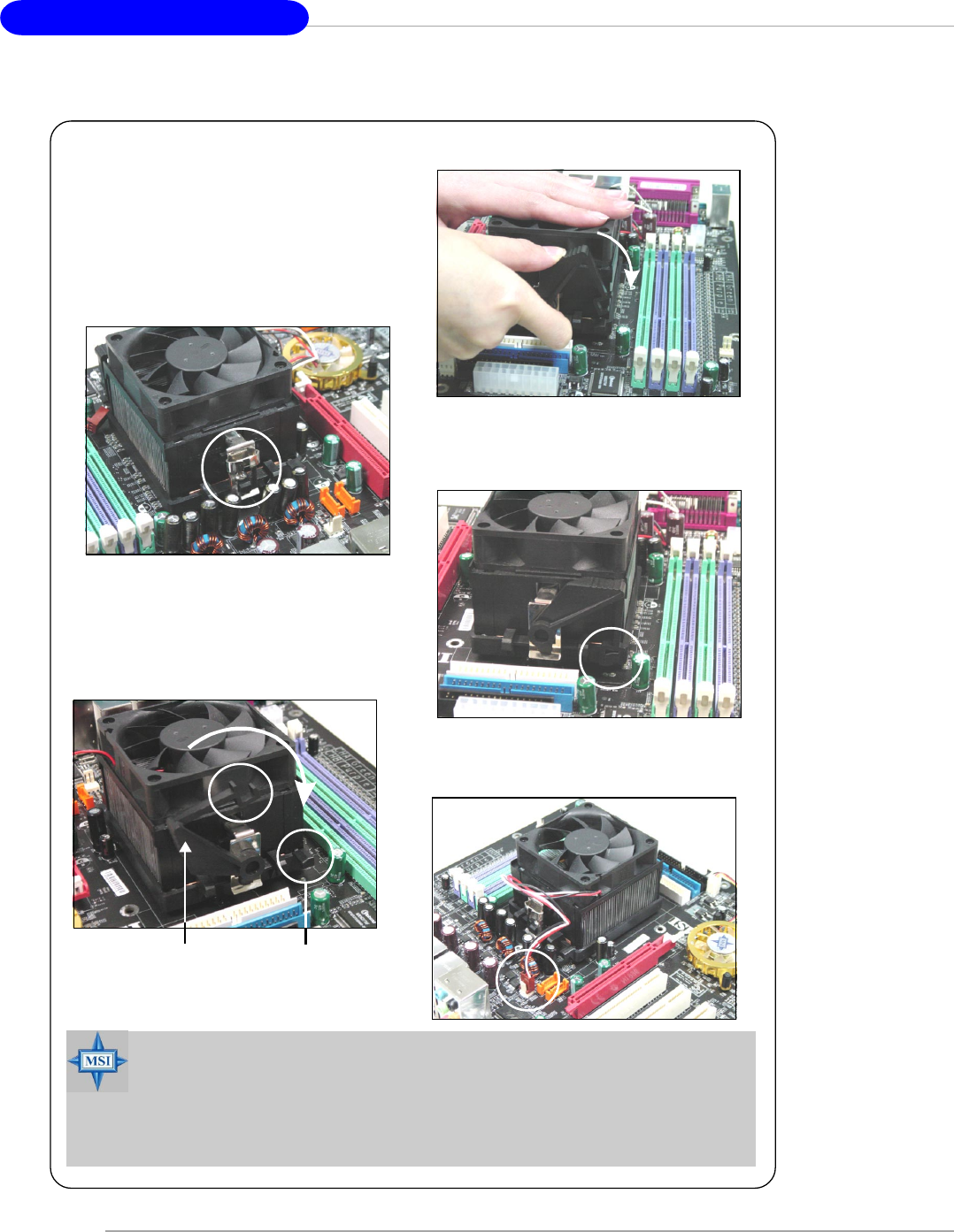
6. Locate the Fix Lever, Safety Hook
and the Fixed Bolt.
Lift up the intensive fixed lever.
5. Position the cooling set onto the re-
tention mechanism.
Hook one end of the clip to hook first,
and then press down the other end
of the clip to fasten the cooling set
on the top of the retention mechanism.
7. Fasten down the lever.
8. Make sure the safety hook completely
clasps the fixed bolt of the retention
mechanism.
Safety Hook
Fixed Bolt
Fixed Lever
9. Attach the CPU Fan cable to the CPU
fan connector on the mainboard.
MSI Reminds You...
While disconnecting the Safety Hook from the fixed bolt, it is neces-
sary to keep an eye on your fingers, because once the Safety Hook is
disconnected from the fixed bolt, the fixed lever will spring back instantly.
Hardware Setup
E-2-7
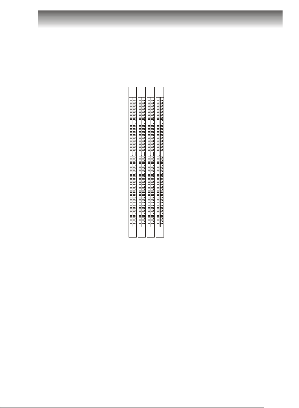
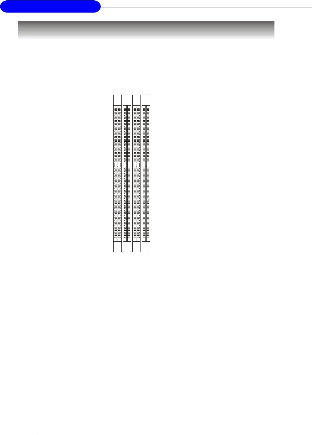
Memory
DIMM1~4
(from left to right)
The mainboard provides 4 slots for 184-pin DDR SDRAM DIMM (Double In-Line Memory
Module) modules and supports the memory size up to 4GB. You can install DDR266/
333/400 modules on the DDR DIMM slots (DDR 1~4).
For the updated supporting memory modules, please visit http://www.msi.com.tw/
program/products/mainboard/mbd/pro_mbd_trp_list.php.
DIMM Module Combination
Install at least one DIMM module on the slots. Each DIMM slot supports up to a maximum
size of 1GB. Users can install either single- or double-sided modules to meet their
own needs. Please note that each DIMM can work respectively for single-
channel DDR, but there are some rules while using dual-channel DDR (Please
refer to the suggested DDR population table below). Users may install memory modules
of different type and density on different-channel DDR DIMMs. However, the same
type and density memory modules are necessary while using dual-channel DDR,
or instability may happen. Please refer to the following table for detailed dual-channel
DDR. Other combination not listed below will function as single-channel DDR.
Introduction to DDR SDRAM
DDR (Double Data Rate) SDRAM is similar to conventional SDRAM, but doubles the
rate by transferring data twice per cycle. It uses 2.5 volts as opposed to 3.3 volts
used in SDR SDRAM, and requires 184-pin DIMM modules rather than 168-pin DIMM
modules used by SDR SDRAM. High memory bandwidth makes DDR an ideal solution
for high performance PC, workstations and servers.
MS-7125 M-ATX Mainboard
E-2-8
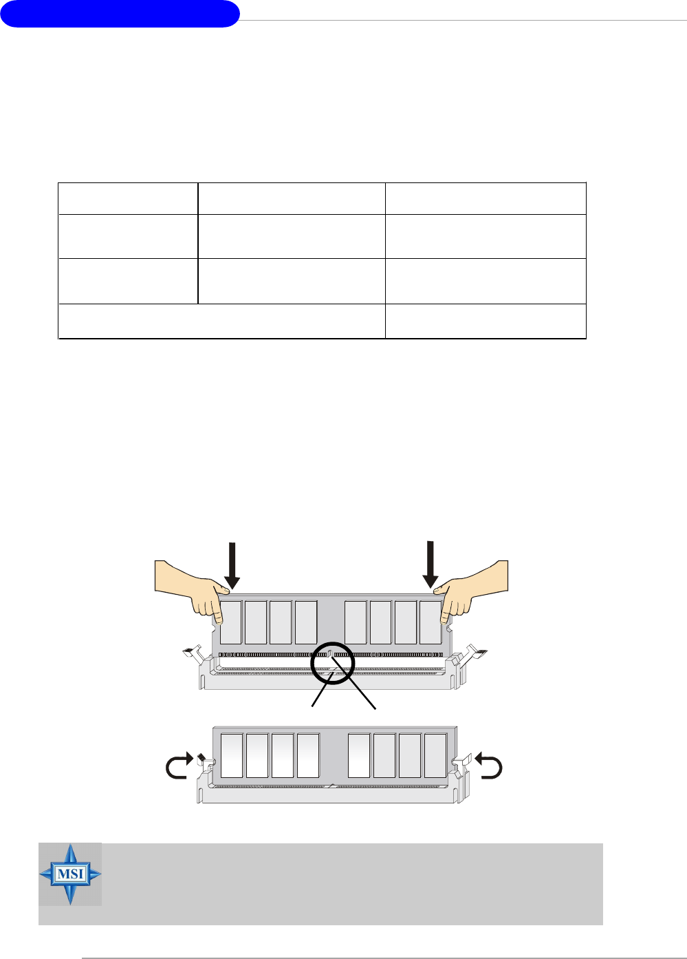
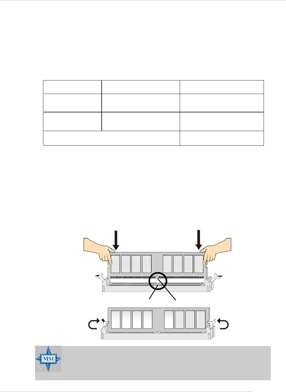
Installing DDR Modules
1. The DDR DIMM has only one notch on the center of module. The module will
only fit in the right orientation.
2. Insert the DIMM memory module vertically into the DIMM slot. Then push it in
until the golden finger on the memory module is deeply inserted in the socket.
3. The plastic clip at each side of the DIMM slot will automatically close.
DIMM Module Combination
Install at least one DIMM module on the slots. You can install either single- or double-
sided modules in any order to meet your own needs.
Memory modules can be installed in any combination as follows:
S: Single Side D: Double Side
Slot Memory Module Total Memory
DDR 2
(Bank 2 & 3) S/D 64MB~1GB
Maximum System Memory Supported 64MB~2GB
DDR 1
(Bank 0 & 1) S/D 64MB~1GB
Volt Notch
MSI Reminds You...
You can barely see the golden finger if the module is properly in-
serted in the socket.
Hardware Setup
E-2-9
Power Supply
The mainboard supports ATX power supply for the power system. Before inserting
the power supply connector, always make sure that all components are installed
properly to ensure that no damage will be caused.
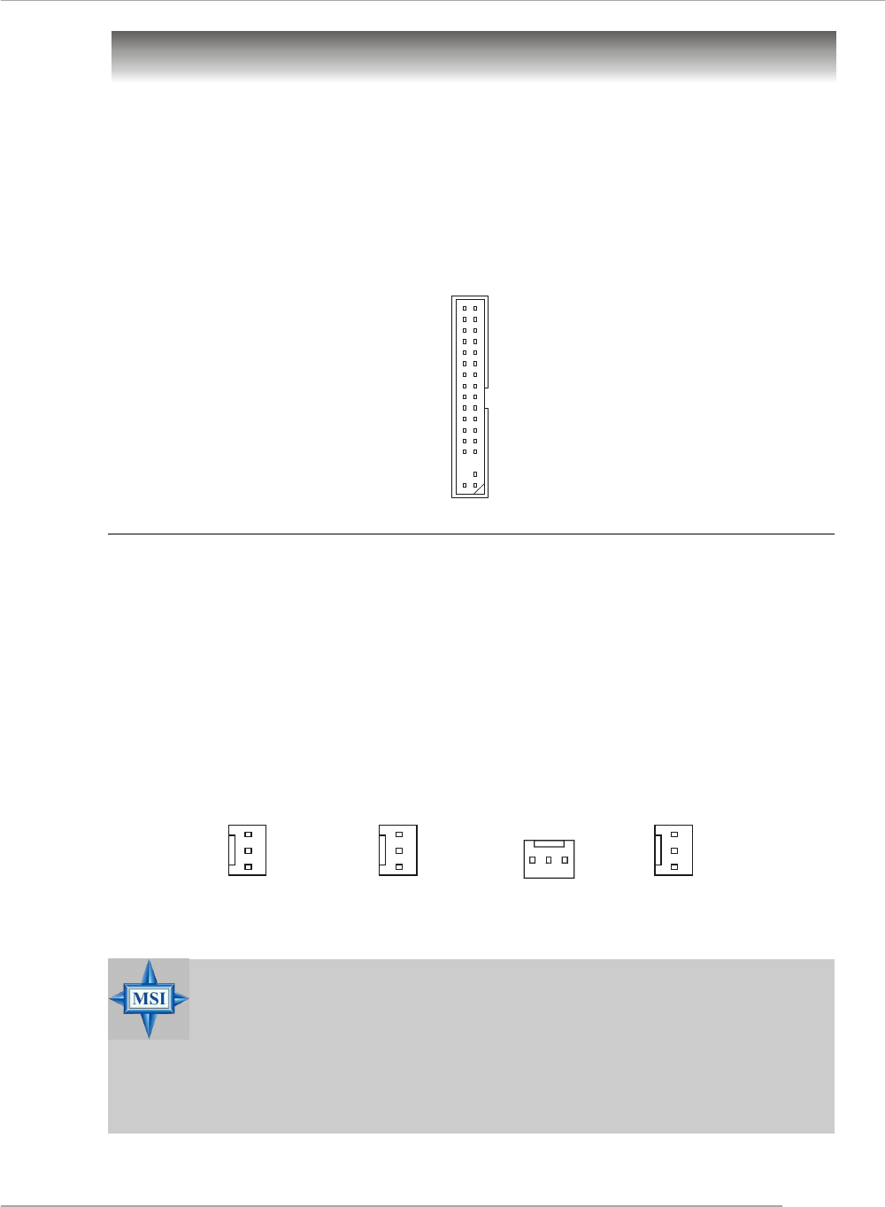
PIN SIGNAL
13 +3.3V
14 -12V
15 GND
16 PS-ON#
17 GND
18 GND
19 GND
20 Res
21 +5V
22 +5V
23 +5V
24 GND
PIN SIGNAL
1 +3.3V
2 +3.3V
3 GND
4 +5V
5 GND
6 +5V
7 GND
8 PWR OK
9 5VSB
10 +12V
11 +12V
12 N C
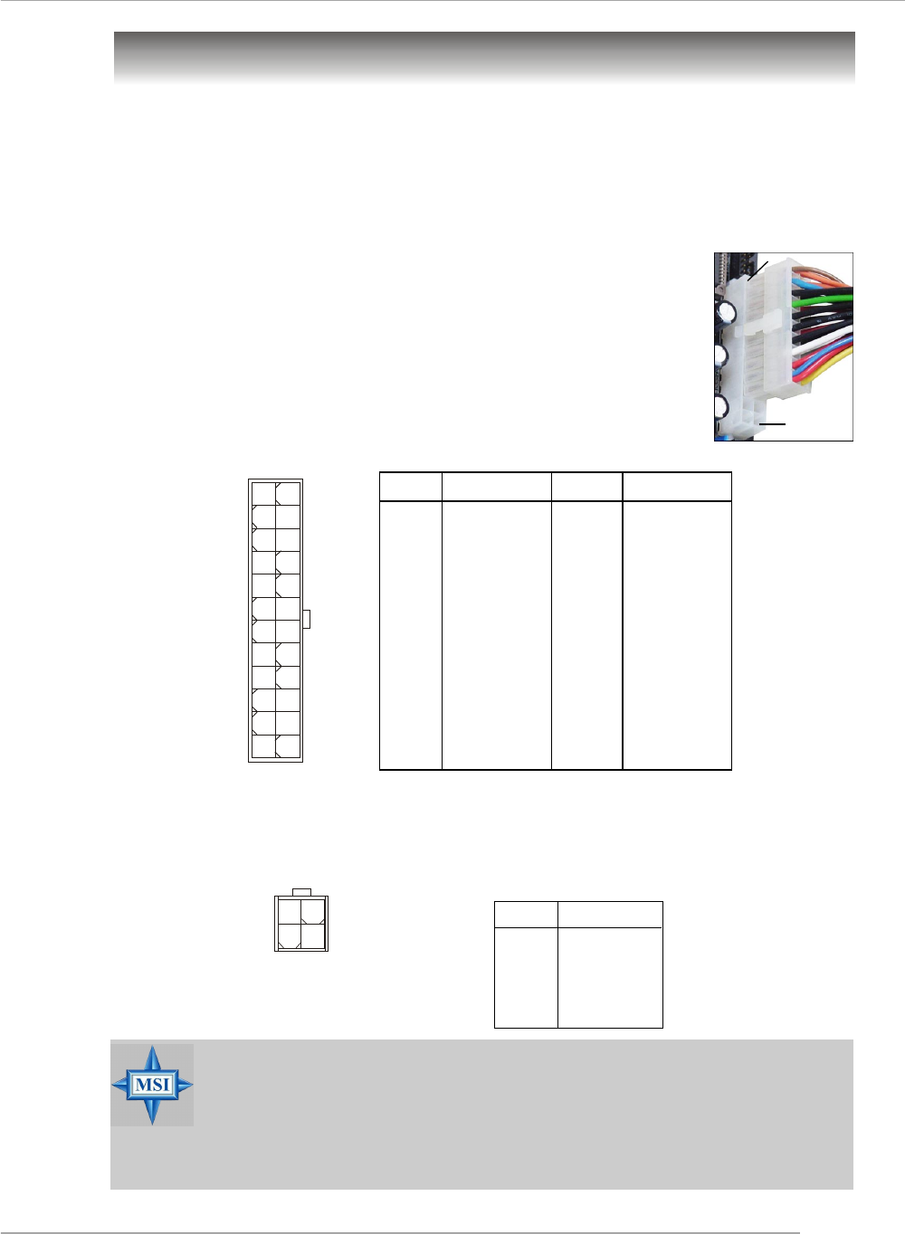
Pin Definition
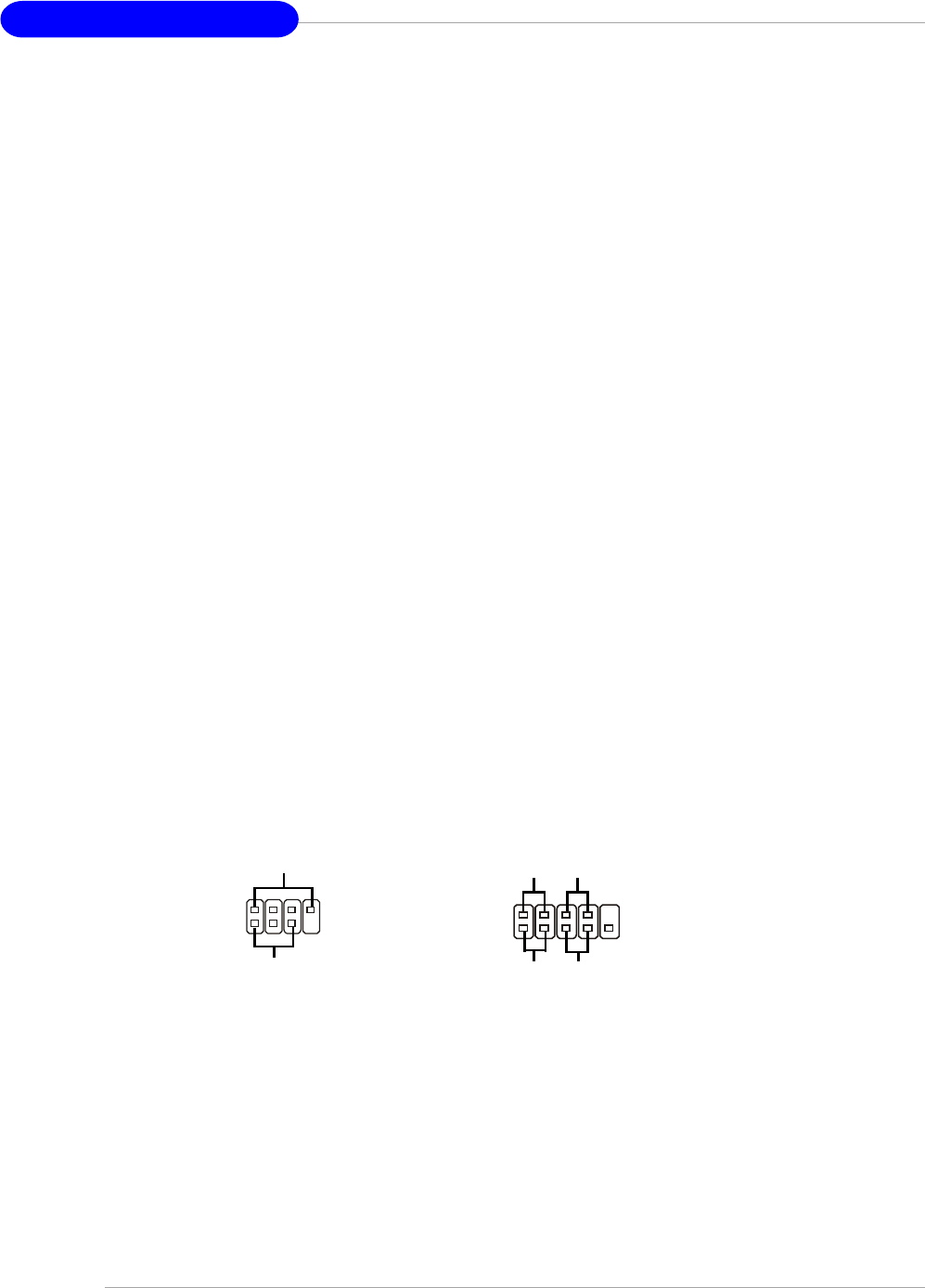
ATX 24-Pin Power Connector: ATX1
This connector allows you to connect an SSI power supply. To connect the
SSI power supply, make sure the plug of the power supply is
inserted in the proper orientation and the pins are aligned. Then
push down the power supply firmly into the connector.
You may use the 20-pin ATX power supply or 24-pin SSI
power supply as you like. If you’d like to use the ATX power supply,
please plug your power supply along with pin 1 & pin 13 (refer to
the image at the right hand). There is also a foolproof design on pin
11, 12, 23 & 24 to avoid wrong installation. pin 12
pin 13
ATX1
12
113
24
PIN SIGNAL
1 GND
2 GND
3 12V
4 12V
JPW1 Pin Definition
ATX 12V Power Connector: JPW1
This 12V power connector is used to provide power to the CPU.
MSI Reminds You...
1. These two connectors connect to the ATX power supply and have to
work together to ensure stable operation of the mainboard.
2. Power supply of 350 watts (and above) is highly recommended for
system stability.
3. For ATX 12V power connection, it should be greater than 18A.
JPW1
1
3 4
2
MS-7125 M-ATX Mainboard
E-2-10
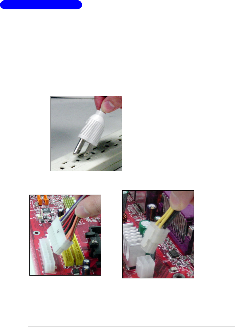
Important Notification about Power Issue
NForce chipset is very sensitive to ESD (Electrostatic Discharge), therefore this
issue mostly happens while the users intensively swap memory modules under S5
(power-off) states, and the power code is plugged while installing modules. Due to
several pins are very sensitive to ESD, so this kind of memory-replacement actions
might cause system chipset unable to boot. Please follow the following solution to
avoid this situation.
Unplug the AC power cable (shown in figure 1) or unplug the ATX1 & JPW1 power
connectors (shown in figure 2 & figure 3) before the 1st installation or during sys-
tem upgrade procedure.
Figure 1:
Unplug the AC power cable
Figure 2:
Unplug the ATX1 power connector Figure 3:
Unplug the JPW1 power connector
Hardware Setup
E-2-11
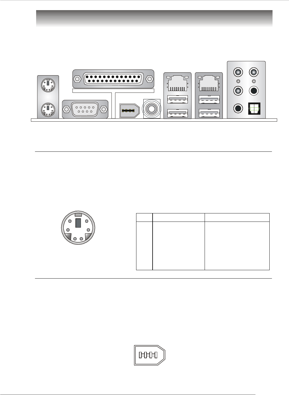
The back panel provides the following connectors:
Back Panel
Mouse Connector (Green) / Keyboard Connector (Purple)
The mainboard provides a standard PS/2® mouse/keyboard mini DIN connector for
attaching a PS/2® mouse/keyboard. You can plug a PS/2® mouse/keyboard directly
into this connector. The connector location and pin assignments are as follows:
PS/2 Mouse / Keyboard
(6-pin Female)
21
3
4
5
6PIN SIGNAL DESCRIPTION
1 Mouse/Keyboard Data Mouse/Keyboard data
2 NC No connection
3 GND Ground
4 VCC +5V
5 Mouse/Keyboard Clock Mouse/Keyboard clock
6 NC No connection
Pin Definition
Keyboard COM Port USB Ports L-Out
Mic
L-In
Mouse Parallel LAN
(Optional)
1394 Port
(Optional) SPDIF
Out
(Coaxial)
RS-Out
CS-Out
SPDIF Out
(Optical)
IEEE1394 Port (Optional)
The back panel provides one standard IEEE 1394 port. The standard IEEE1394 port
connects to IEEE1394 devices without external power. The IEEE1394 high-speed
serial bus complements USB by providing enhanced PC connectivity for a wide range
of devices, including consumer electronics audio/video (A/V) appliances, storage
peripherals, other PCs, and portable devices.
IEEE1394 Port
LAN
(Optional)
MS-7125 M-ATX Mainboard
E-2-12
USB Connectors
The mainboard provides two OHCI (Open Host Controller Interface) Universal Serial
Bus roots for attaching USB devices such as keyboard, mouse or other USB-com-
patible devices. You can plug the USB device directly into the connector.
USB Ports
1 2 3 4
5 6 7 8
PIN SIGNAL DESCRIPTION
1 VCC +5V
2 -Data 0 Negative Data Channel 0
3 +Data0 Positive Data Channel 0
4 GND Ground
5 VCC +5V
6 -Data 1 Negative Data Channel 1
7 +Data 1 Positive Data Channel 1
8 GND Ground
USB Port Description
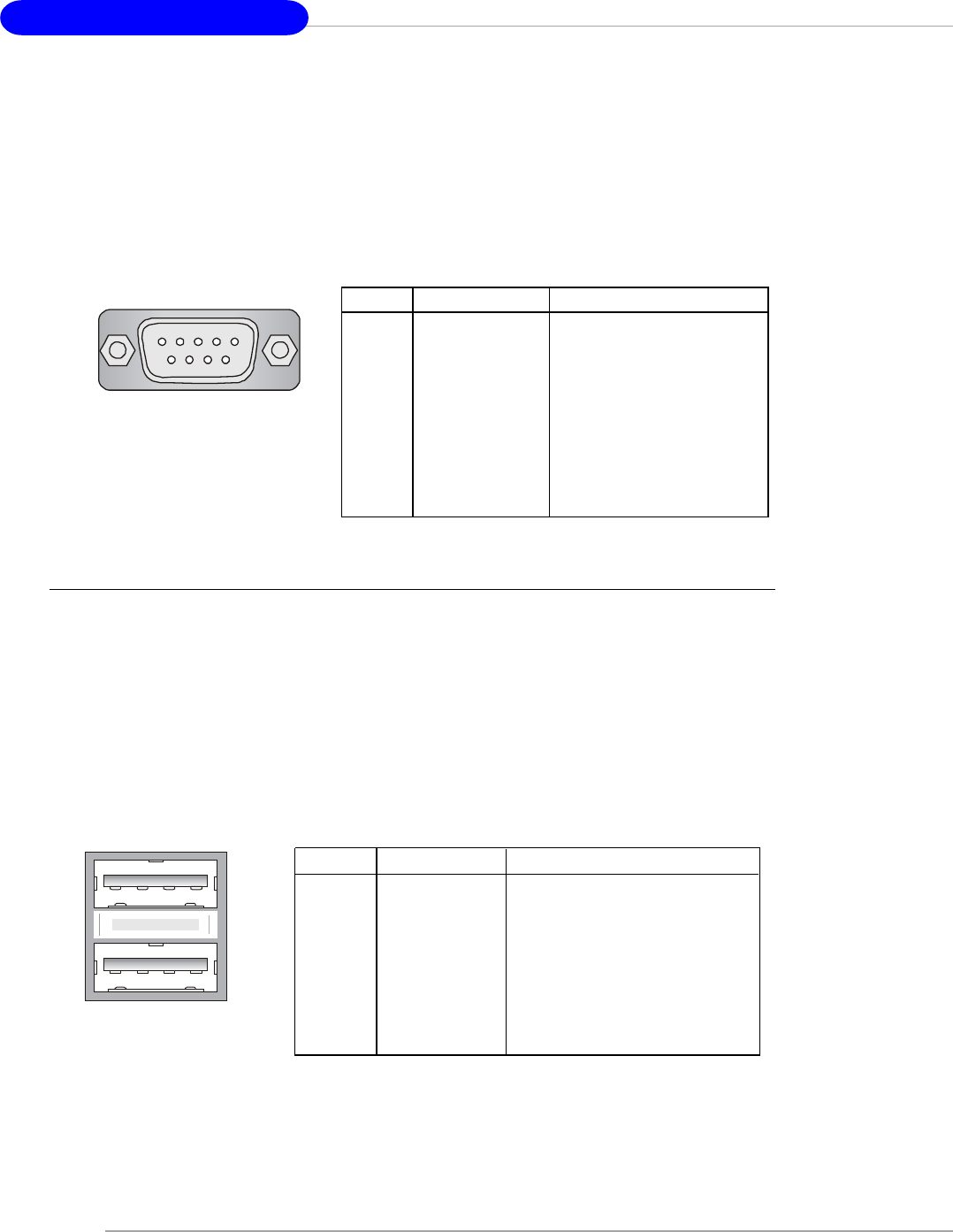
Serial Port Connector
The mainboard offers one 9-pin male DIN connector as the serial port. The port is a
16550A high speed communication port that sends/receives 16 bytes FIFOs. You
can attach a serial mouse or other serial devices directly to the connector.
PIN SIGNAL DESCRIPTION
1 DCD Data Carry Detect
2 SIN Serial In or Receive Data
3 SOUT Serial Out or Transmit Data
4 DTR Data Terminal Ready)
5 GND Ground
6 DSR Data Set Ready
7 RTS Request To Send
8 CTS Clear To Send
9 RI Ring Indicate
Pin Definition
9-Pin Male DIN Connector
1 2 3 4 5
6 7 8 9
Hardware Setup
E-2-13
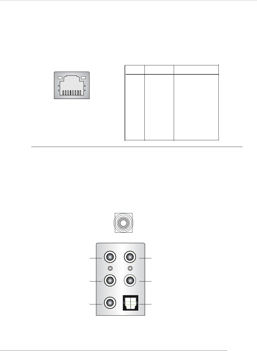
LAN (RJ-45) Jack (Optional)
The mainboard provides 2 standard RJ-45 jacks for connection to single Local Area
Network (LAN). This Giga-bit LAN enables data to be transferred at 1000, 100 or
10Mbps. You can connect a network cable to either LAN jack.
Audio Port Connectors
The left 3 audio jacks are for 2-channel mode for stereo speaker output: Line Out is
a connector for Speakers or Headphones. Line In is used for external CD player,
Tape player, or other audio devices. Mic is a connector for microphones.
However, there is an advanced audio application provided by Realtek ALC850 to
offer support for 7.1-channel audio operation and can turn rear audio connectors
from 2-channel to 4-/5.1-/7.1 channel audio.
S/PDIF Out-Coaxial
Rear Speaker Out
(in 7.1CH / 6CH / 4CH)
Line Out
Line In
( in 7.1CH / 6CH)
MIC
Center/Subwoofer
Speaker Out
( in 7.1CH / 6CH)
S/PDIF Out-Optical
(in 7.1CH / 6CH)
Giga-bit LAN Pin Definition
PIN SIGNAL DESCRIPTION
1 D0P Differential Pair 0+
2 D0N Differential Pair 0-
3 D1P Differential Pair 1+
4 D2P Differential Pair 2+
5 D2N Differential Pair 2-
6 D1N Differential Pair 1-
7 D3P Differential Pair 3+
8 D3N Differential Pair 3-
RJ-45 LAN Jack
MS-7125 M-ATX Mainboard
E-2-14
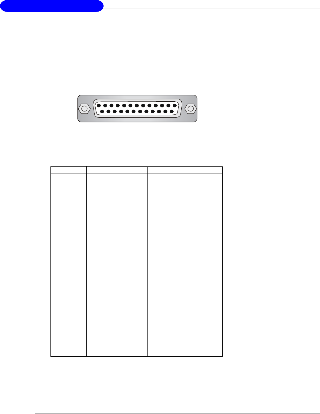
Parallel Port Connector: LPT1
The mainboard provides a 25-pin female centronic connector as LPT. A parallel port
is a standard printer port that supports Enhanced Parallel Port (EPP) and Extended
Capabilities Parallel Port (ECP) mode.
13 1
14
25
PIN SIGNAL DESCRIPTION
1 STROBE Strobe
2 DATA0 Data0
3 DATA1 Data1
4 DATA2 Data2
5 DATA3 Data3
6 DATA4 Data4
7 DATA5 Data5
8 DATA6 Data6
9 DATA7 Data7
10 ACK# Acknowledge
11 BUSY Busy
12 PE Paper End
13 SELECT Select
14 AUTO FEED# Automatic Feed
15 ERR# Error
16 INIT# Initialize Printer
17 SLIN# Select In
18 GND Ground
19 GND Ground
20 GND Ground
21 GND Ground
22 GND Ground
23 GND Ground
24 GND Ground
25 GND Ground
Pin Definition
Hardware Setup
E-2-15
The mainboard provides connectors to connect to FDD, IDE HDD, case, LAN, USB
Ports, IR module and CPU/System FAN.
Floppy Disk Drive Connector: FDD1
The mainboard provides a standard floppy disk drive connector that supports 360K,
720K, 1.2M, 1.44M and 2.88M floppy disk types.
Connectors
FDD1
Fan Power Connectors: CPUFAN1 / SFAN1 / SFAN2 / NBFAN1
The CPUFAN1 (processor fan), SFAN1 (system fan 1), SFAN2 (system fan 2) and
NBFAN1 (NorthBridge Chipset fan) support system cooling fan with +12V. It supports
three-pin head connector. When connecting the wire to the connectors, always take
note that the red wire is the positive and should be connected to the +12V, the black
wire is Ground and should be connected to GND. If the mainboard has a System
Hardware Monitor chipset on-board, you must use a specially designed fan with
speed sensor to take advantage of the CPU fan control.
SFAN2 NBFAN1
+12V
GND
Sensor
CPUFAN1
SENSOR
+12V
GND
SFAN1
+12V
GND
MSI Reminds You...
1. Always consult the vendors for proper CPU cooling fan.
2. CPUFAN1 supports fan control. You can install Core Center util-
ity that will automatically control the CPU fan speed according to
the actual CPU temperature.
3. Please refer to the recommended CPU fans at AMD® official
website.
+12V
GND
NC
SENSOR
MS-7125 M-ATX Mainboard
E-2-16
Hard Disk Connectors: IDE1 / IDE2
The mainboard has a 32-bit Enhanced PCI IDE and Ultra DMA 33/66/100/133 controller
that provides PIO mode 0~4, Bus Master, and Ultra DMA 33/66/100/133 function. You
can connect up to four hard disk drives, CD-ROM, or other devices.
IDE1 (Primary IDE Connector)
The first hard drive should always be connected to IDE1. IDE1 can connect a Master
and a Slave drive. You must configure second hard drive to Slave mode by setting the
jumper accordingly.
IDE2 (Secondary IDE Connector)
IDE2 can also connect a Master and a Slave drive.
IDE1IDE2
MSI Reminds You...
If you install two hard disks on cable, you must configure the second
drive to Slave mode by setting its jumper. Refer to the hard disk
documentation supplied by hard disk vendors for jumper setting
instructions.
Chassis Intrusion Switch Connector: JCI1
This connector is connected to a 2-pin chassis switch. If the chas-
sis is opened, the switch will be short. The system will record this
status and show a warning message on the screen. To clear the
warning, you must enter the BIOS utility and clear the record. JCI1
2
1
GND
CINTRU
Hardware Setup
E-2-17
CD-In Connector: JCD1
The connector is for CD-ROM audio connector. JCD1
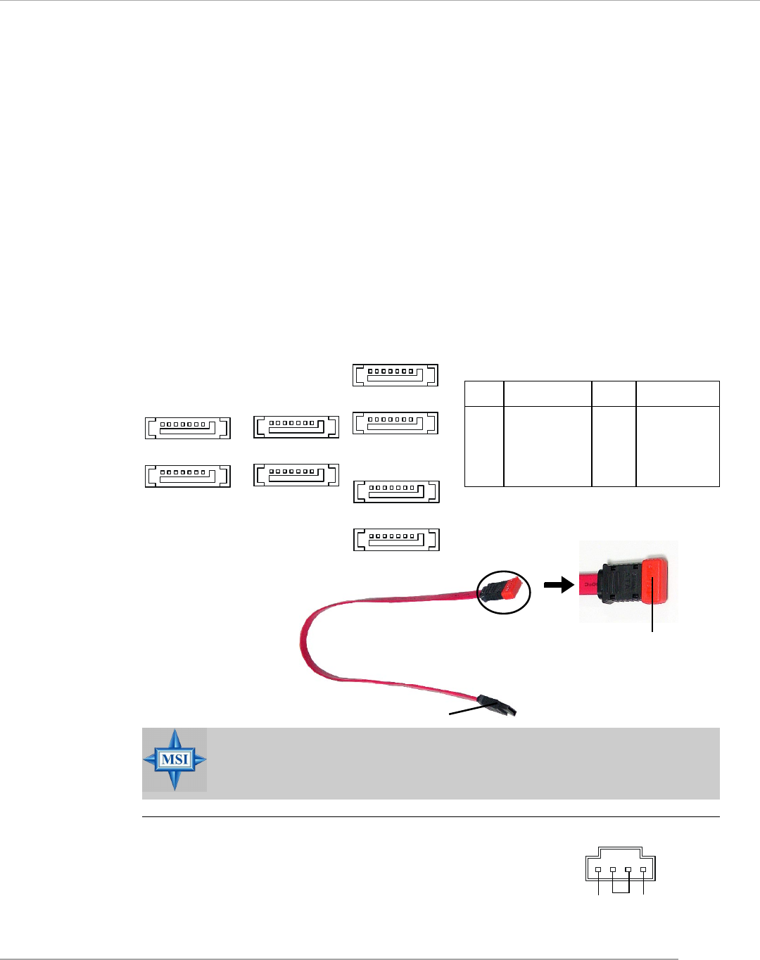
Serial ATA/Serial ATA RAID Connectors controlled by
nForce4 Ultra: SATA1 / SATA2 / SATA3 / SATA4;
Serial ATA/Serial ATA RAID Connectors controlled by
Silicon Image’s SATARAID5TM: SATA5 / SATA6 / SATA7 / SATA8
(Optional)
The Southbridge of this mainboard is nForce4 Ultra which supports four serial
ATA connectors SATA1~SATA4. Silicon Image’s SATARAID5TM of this mainboard sup-
ports another four serial ATA connectors SATA5~SATA8.
SATA1~SATA8 are dual high-speed Serial ATA interface ports. Each supports
1st generation serial ATA data rates of 300MB/s(SATA1-4)/150 MB/s(SATA5-8). Both
connectors are fully compliant with Serial ATA 1.0 specifications. Each Serial ATA
connector can connect to 1 hard disk device. Please refer to the nVidia RAID
Introduction & Silicon Image RAID Introduction for detail software installation
procedure.
GND
RL
MSI Reminds You...
Please do not fold the serial ATA cable in a 90-degree angle, which will
cause the loss of data during the transmission.
Take out the dust cover
and connect to the hard
disk devices
PIN SIGNAL PIN SIGNAL
1 GND 2 TXP
3 TXN 4 GND
5 RXN 6 RXP
7 GND
SATA1~ SATA8 Pin Definition
SATA6
SATA5
1
7
SATA7
SATA8
1
7
SATA4
SATA2
SATA1
1
7
SATA3
1
7
Serial ATA cable
(Optional)
Connect to serial ATA ports
MS-7125 M-ATX Mainboard
E-2-18
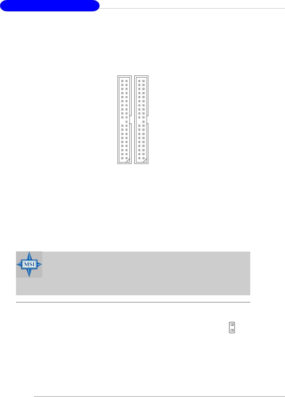
Front Panel Connectors: JFP1 / JFP2
The mainboard provides two front panel connectors for electrical connection
to the front panel switches and LEDs. JFP1 is compliant with Intel® Front Panel I/O
Connectivity Design Guide.
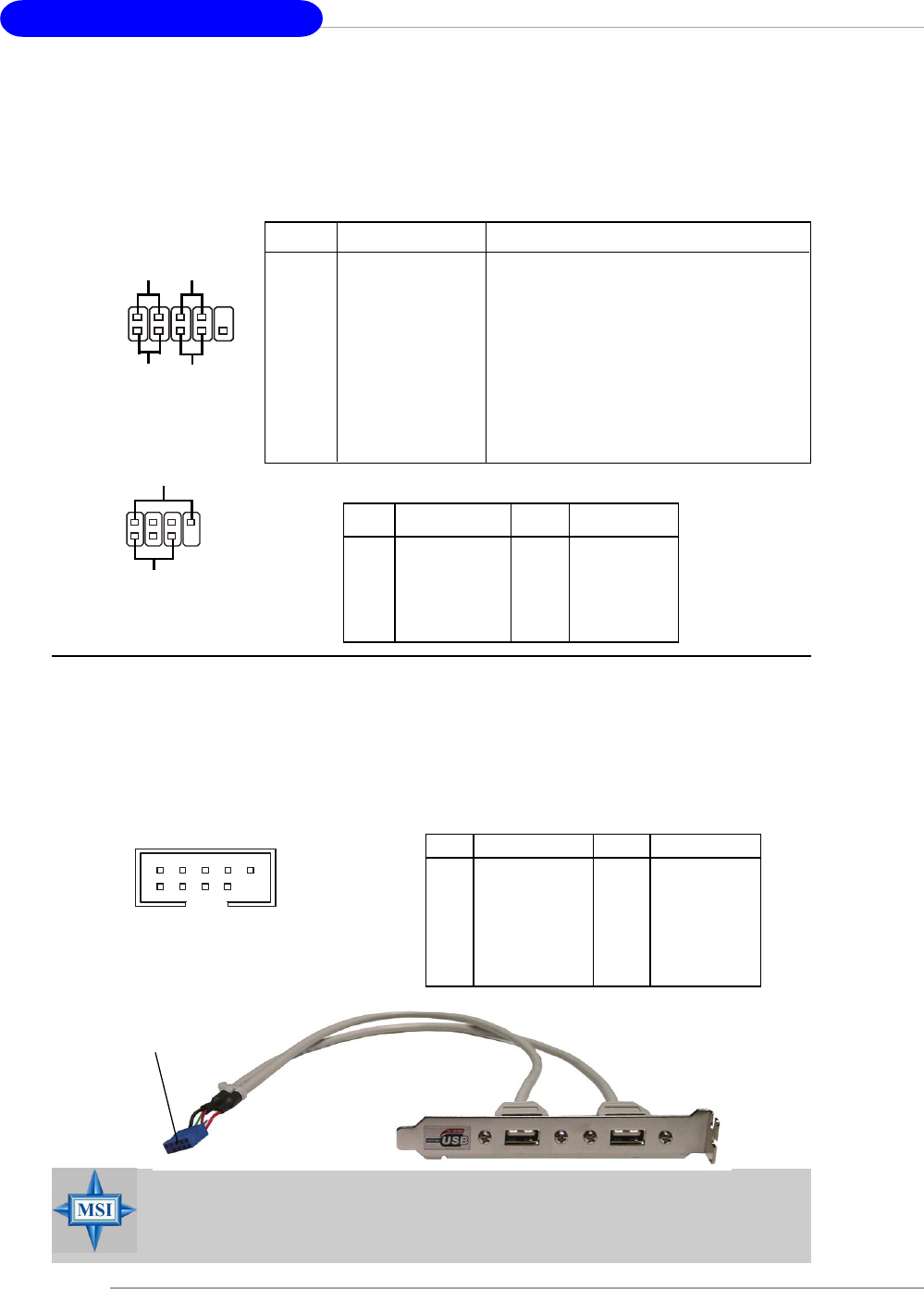
Front USB Connectors: JUSB1 / JUSB2 / JUSB3
The mainboard provides three standard USB 2.0 pin headers JUSB1 & JUSB2
& JUSB3. USB 2.0 technology increases data transfer rate up to a maximum throughput
of 480Mbps, which is 40 times faster than USB 1.1, and is ideal for connecting high-
speed USB interface peripherals such as USB HDD, digital cameras, MP3 players,
printers, modems and the like.
MSI Reminds You...
Note that the pins of VCC and GND must be connected correctly, or it
may cause some damage.
7
8
Power
LED
Speaker
1
2
JFP2
JFP1 19
10
2
Power
LED Power
Switch
Reset
Switch
HDD
LED
PIN SIGNAL DESCRIPTION
1 HD_LED_P Hard disk LED pull-up
2 FP PWR/SLP MSG LED pull-up
3 HD_LED_N Hard disk active LED
4 FP PWR/SLP MSG LED pull-up
5 RST_SW_N Reset Switch low reference pull-down to GND
6 PWR_SW_P Power Switch high reference pull-up
7 RST_SW_P Reset Switch high reference pull-up
8 PWR_SW_N Power Switch low reference pull-down to GND
9 RSVD_DNU Reserved. Do not use.
JFP1 Pin Definition
PIN SIGNAL PIN SIGNAL
1 GND 2 SPK-
3 SLED 4 BUZ+
5 PLED 6 BUZ-
7 NC 8 SPK+
JFP2 Pin Definition
PIN SIGNAL PIN SIGNAL
1 VCC 2 VCC
3 USB0- 4 USB1-
5 USB0+ 6 USB1+
7 GND 8 GND
9 Key (no pin) 10 USBOC
JUSB1 & JUSB2 & JUSB3 Pin Definition
JUSB1, JUSB2, JUSB3
(USB 2.0)
1
2 10
9
Connected to JUSB1, JUSB2, or
JUSB3 (the USB pinheader in
YELLOW color) USB 2.0 Bracket
(Optional)
Hardware Setup
E-2-19
Front Panel Audio Connector: JAUD1
The JAUD1 front panel audio connector allows you to connect to the front
panel audio and is compliant with Intel® Front Panel I/O Connectivity Design Guide.
JAUD1
1
29
10
PIN SIGNAL DESCRIPTION
1 AUD_MIC Front panel microphone input signal
2 AUD_GND Ground used by analog audio circuits
3 AUD_MIC_BIAS Microphone power
4 AUD_VCC Filtered +5V used by analog audio circuits
5 AUD_FPOUT_R Right channel audio signal to front panel
6 AUD_RET_R Right channel audio signal return from front panel
7 HP_ON Reserved for future use to control headphone amplifier
8 KEY No pin
9 AUD_FPOUT_L Left channel audio signal to front panel
10 AUD_RET_L Left channel audio signal return from front panel
Pin Definition
MSI Reminds You...
If you don’t want to connect to the front audio header,
pins 5 & 6, 9 & 10 have to be jumpered in order to have
signal output directed to the rear audio ports. Otherwise,
the Line-Out connector on the back panel will not
function. 5
610
9
IrDA Infrared Module Header: JIR1
The connector allows you to connect to IrDA Infrared module. You must con-
figure the setting through the BIOS setup to use the IR function. JIR1 is compliant with
Intel® Front Panel I/O Connectivity Design Guide.
JIR1
JIR1 Pin Definition
6 5
21
Pin Signal Pin Signal
1NC 2 NC
3 VCC5 4 GND
5 IRTX 6 IRRX
MS-7125 M-ATX Mainboard
E-2-20
Foolproof
design
Connected to J1394 (the 1394
pinheader in GREEN color)
IEEE1394 Bracket (Optional)
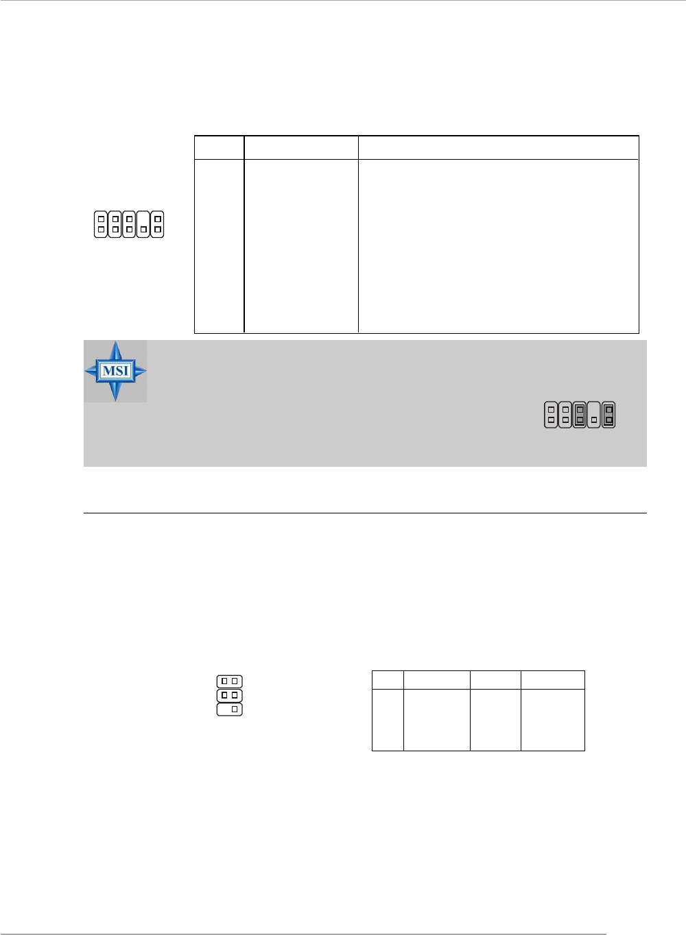
IEEE 1394 Connectors: J1394_1 (Optional)
The mainboard provides another 1394 pin header that allows you to connect
IEEE 1394 ports via an external IEEE1394 bracket (optional).
Pin Definition
PIN SIGNAL PIN SIGNAL
1TPA+ 2 TPA-
3 Ground 4 Ground
5 TPB+ 6 TPB-
7 Cable power 8 Cable power
9 Key (no pin) 10 Ground
J1394_1
1
2 9
10
Hardware Setup
E-2-21
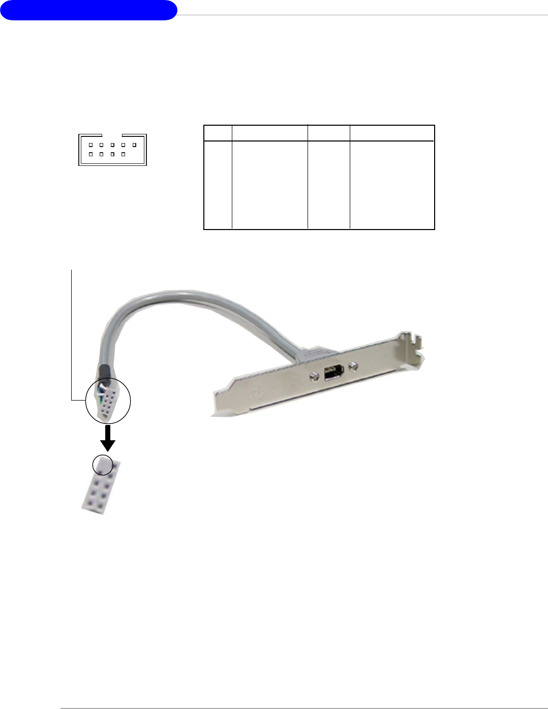
D-Bracket™ 2 Connector: JDB1
The mainboard comes with a JDB1 connector for you to connect to D-Bracket™ 2. D-
Bracket™ 2 is a USB Bracket that supports both USB1.1 & 2.0 spec. It integrates four
LEDs and allows users to identify system problem through 16 various combinations
of LED signals.
Pin Signal
1 DBG1 (high for green color)
2 DBR1 (high for red color)
3 DBG2 (high for green color)
4 DBR2 (high for red color)
5 DBG3 (high for green color)
6 DBR3 (high for red color)
7 DBG4 (high for green color)
8 DBR4 (high for red color)
9 Key
10 NC
Pin Definition
JDB1
1 9
2 10
D-Bracket™ 2
(Optional)
Connected to JUSB1, JUSB2 or JUSB3
(the USB pinheader in YELLOW color)
Connected to JDB1
LEDs
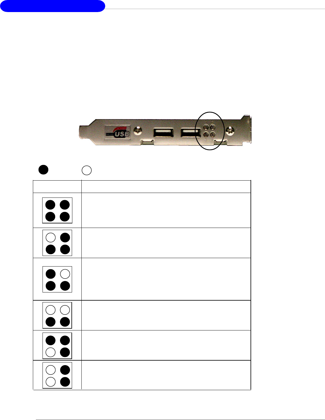
MS-7125 M-ATX Mainboard
E-2-22
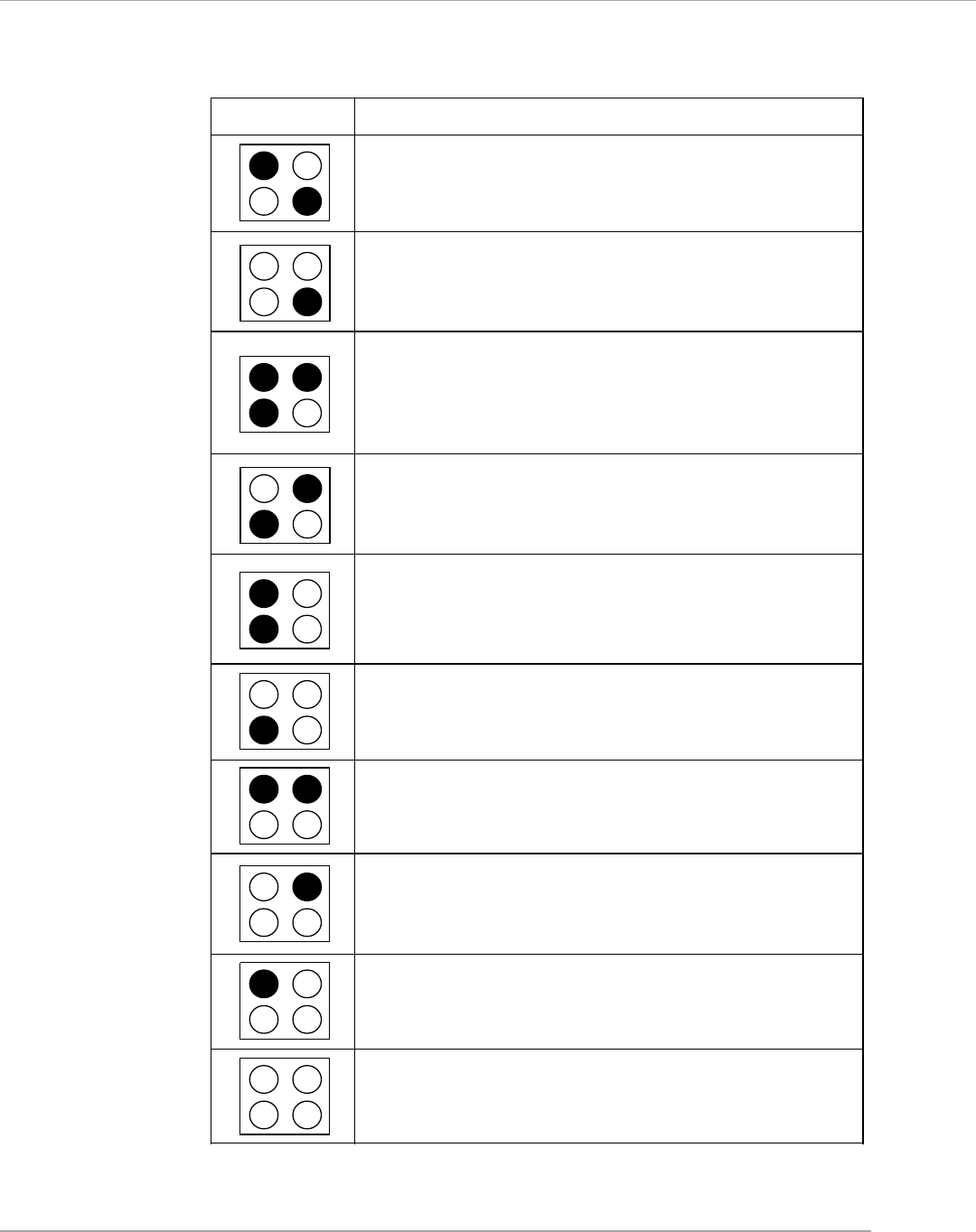
Red Green
Description
System Power ON
The D-LED will hang here if the processor is damaged or
not installed properly.
Early Chipset Initialization
Memory Detection Test
Testing onboard memory size. The D-LED will hang if the
memory module is damaged or not installed properly.
Decompressing BIOS image to RAM for fast booting.
1 2
3 4
Initializing Keyboard Controller.
Testing VGA BIOS
This will start writing VGA sign-on message to the screen.
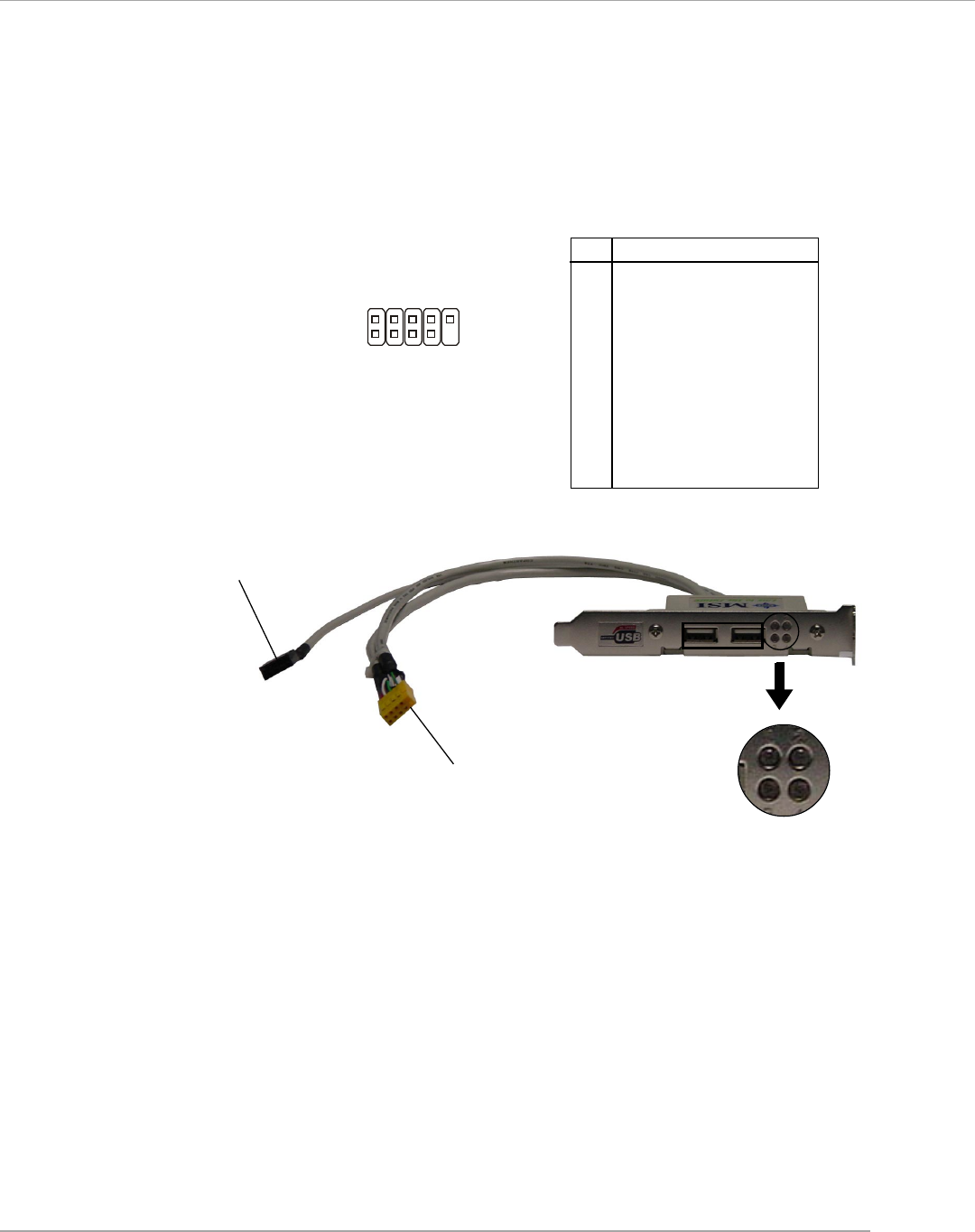
D-Bracket™ 2
D-Bracket™ 2 is an external USB bracket integrating four Diagnostic LEDs, which
use graphic signal display to help users understand their system. The LEDs provide
up to 16 combinations of signals to debug the system. The 4 LEDs can debug all
problems that fail the system, such as VGA, RAM or other failures. This special
feature is very useful for the overclocking users. These users can use the feature to
detect if there are any problems or failures.
D-Bracket™ 2 supports both USB 1.1 & 2.0 specification.
D-Bracket™ 2 1 2
3 4
Hardware Setup
E-2-23
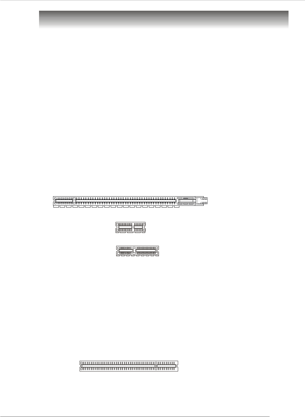
D-Bracket™ 2 Description
Processor Initialization
This will show information regarding the processor (like
brand name, system bus, etc...)
Testing RTC (Real Time Clock)
Initializing Video Interface
This will start detecting CPU clock, checking type of video
onboard. Then, detect and initialize the video adapter.
BIOS Sign On
This will start showing information about logo, proces-
sor brand name, etc...
Testing Base and Extended Memory
Testing base memory from 240K to 640K and extended
memory above 1MB using various patterns.
Assign Resources to all ISA.
Initializing Hard Drive Controller
This will initialize IDE drive and controller.
Initializing Floppy Drive Controller
This will initialize Floppy Drive and controller.
Boot Attempt
This will set low stack and boot via INT 19h.
Operating System Booting
1 2
3 4

MS-7125 M-ATX Mainboard
E-2-24
The motherboard provides the following button for you to set the computer’s
function. This section will explain how to change your motherboard’s function through
the use of button.
Button
Clear CMOS Button: SW1
There is a CMOS RAM on board that has a power supply from external battery
to keep the system configuration data. With the CMOS RAM, the system can auto-
matically boot OS every time it is turned on. If you want to clear the system
configuration, use the SW1 (Clear CMOS Button ) to clear data. Press the button in
the middle of the connector top side to clear the data.
SW1
Hardware Setup
E-2-25
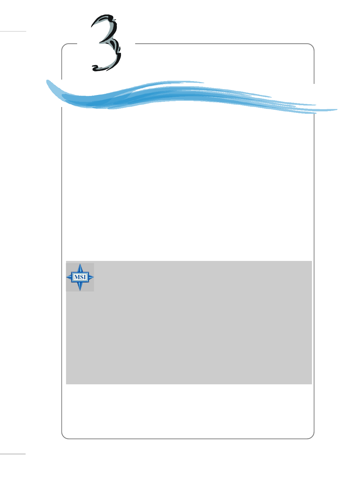
Slots
PCI Express Slots
The PCI Express slots, as a high-bandwidth, low pin count, serial, intercon-
nect technology. You can insert the expansion cards to meet your needs. When
adding or removing expansion cards, make sure that you unplug the power supply
first. PCI Express architecture provides a high performance I/O infrastructure for
Desktop Platforms with transfer rates starting at 2.5 Giga transfers per second over
a PCI Express x1 lane for Gigabit Ethernet, TV Tuners, 1394 controllers, and general
purpose I/O. Also, desktop platforms with PCI Express Architecture will be designed
to deliver highest performance in video, graphics, multimedia and other sophisticated
applications. Moreover, PCI Express architecture provides a high performance graphics
infrastructure for Desktop Platforms doubling the capability of existing AGP8x de-
signs with transfer rates of 4.0 GB/s over a PCI Express x16 lane for graphics
controllers, while PCI Express x1 supports transfer rate of 250 MB/s.
The mainboard provides one PCI Express x16 slot, one PCI Express x1 slot,
one PCI Express x4 slot and four 32-bit PCI bus slots.
PCI Express x1 slot
PCI Express x16 slot
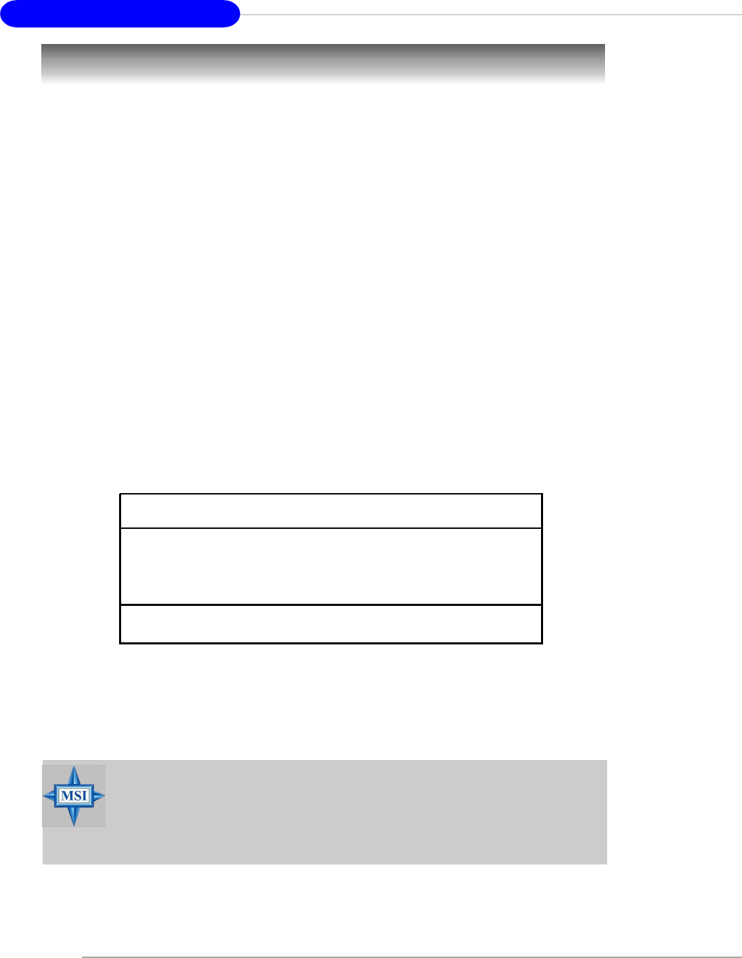
PCI (Peripheral Component Interconnect) Slots
The PCI slots allow you to insert the expansion cards to meet your needs.
When adding or removing expansion cards, make sure that you unplug the power
supply first. Meanwhile, read the documentation for the expansion card to make any
necessary hardware or software settings for the expansion card, such as jumpers,
switches or BIOS configuration.
The orange PCI slot (PCI4) also works as a communcation slot, which allows
you to insert the communcation card.
PCI Slots
PCI Express x4 slot
(supports PCI-E x2 device only)

MS-7125 M-ATX Mainboard
E-2-26
PCI Interrupt Request Routing
The IRQ, acronym of interrupt request line and pronounced I-R-Q, are hard-
ware lines over which devices can send interrupt signals to the microprocessor. The
PCI IRQ pins are typically connected to the PCI bus INT A# ~ INT D# pins as follows:
Order 1 Order 2 Order 3 Order 4
PCI Slot 1 INT A# INT B# INT C# INT D#
PCI Slot 2 INT B# INT C# INT D# INT A#
PCI Slot 3 INT C# INT D# INT A# INT B#
PCI Slot 4 INT D# INT A# INT B# INT C#
BIOS Setup
E-3-1
Chapter 3. BIOS Setup
BIOS Setup
This chapter provides information on the BIOS Setup program and allows you
to configure the system for optimum use.
You may need to run the Setup program when:
An error message appears on the screen during the system
booting up, and requests you to run SETUP.
You want to change the default settings for customized
features.
MSI Reminds You...
1. The items under each BIOS category described in this chapter are
under continuous update for better system performance. Therefore,
the description may be slightly different from the latest BIOS and
should be held for reference only.
2. While booting up, the BIOS version is shown in the 1st line appear-
ing after the memory counting. It is usually in the format:
example: W7125NMS V1.0B32 061704
where:
1st digit refers to BIOS maker as A=AMI(R); W=AWARD(R)
2nd - 5th digit refers to the model number.
6th digit refers to nVIDIA chipset.
7th - 8th digit refers to the customer, MS=all standard customers.
V1.0 refers to the BIOS version.
061704 refers to the date this BIOS is released.
MS-7125 M-ATX Mainboard
E-3-2
Entering Setup
Power on the computer and the system will start POST (Power On Self Test) process.
When the message below appears on the screen, press <DEL> key to enter Setup.
Press DEL to enter SETUP
If the message disappears before you respond and you still wish to enter Setup,
restart the system by turning it OFF and On or pressing the RESET button. You may also
restart the system by simultaneously pressing <Ctrl>, <Alt>, and <Delete> keys.
MSI Reminds You...
The items under each BIOS category described in this chapter are
under continuous update for better system performance. Therefore,
the description may be slightly different from the latest BIOS and
should be held for reference only.
Selecting the First Boot Device
You are allowed to select the 1st boot device without entering the BIOS setup utility by
pressing <F11>. When the same message as listed above appears on the screen,
press <F11> to trigger the boot menu.
The POST messages might pass by too quickly for you to respond in time. If so, restart
the system and press <F11> after around 2 or 3 seconds to activate the boot menu
similar to the following.
The boot menu will list all the bootable devices. Select the one you want to boot from by
using arrow keys, then press <Enter>. The system will boot from the selected device.
The selection will not make changes to the settings in the BIOS setup utility, so next time
when you power on the system, it will still use the original first boot device to boot up.
Select First Boot Device
Floppy : 1st Floppy
IDE-0 : IBM-DTLA-307038
CDROM : ATAPI CD-ROM DRIVE 40X M
[Up/Dn] Select [RETURN] Boot [ESC] cancel
BIOS Setup
E-3-3
Control Keys
Getting Help
After entering the Setup menu, the first menu you will see is the Main Menu.
Main Menu
The main menu lists the setup functions you can make changes to. You can use the
arrow keys ( ↑↓ ) to select the item. The on-line description of the highlighted setup
function is displayed at the bottom of the screen.
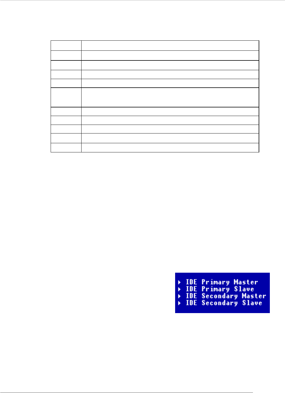
Sub-Menu
If you find a right pointer symbol (as shown in the right view) appears to the left of
certain fields that means a sub-menu can be launched from this field. A sub-menu
contains additional options for a field parameter.
You can use arrow keys ( ↑↓ ) to highlight the
field and press <Enter> to call up the sub-menu.
Then you can use the control keys to enter
values and move from field to field within a
sub-menu. If you want to return to the main
menu, just press the <Esc >.
General Help <F1>
The BIOS setup program provides a General Help screen. You can call up this screen
from any menu by simply pressing <F1>. The Help screen lists the appropriate keys to
use and the possible selections for the highlighted item. Press <Esc> to exit the Help
screen.
<↑> Move to the previous item
<↓> Move to the next item
<←> Move to the item in the left hand
<→> Move to the item in the right hand
<Enter> Select the item
<Esc> Jumps to the Exit menu or returns to the main menu from a
submenu
<+/PU> Increase the numeric value or make changes
<-/PD> Decrease the numeric value or make changes
<F5> Previous Values
<F7> Load Optimized Defaults
<F10> Save all the CMOS changes and exit
MS-7125 M-ATX Mainboard
E-3-4
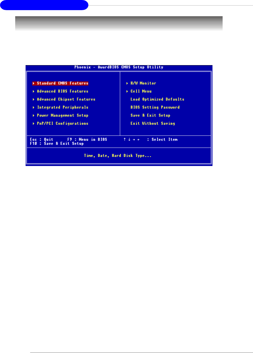
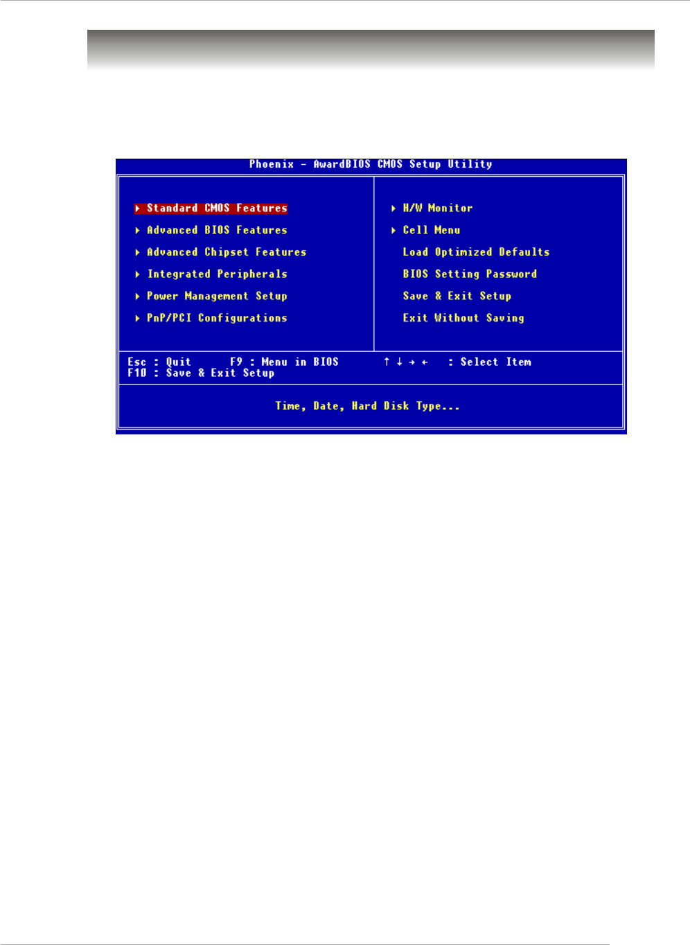
The Main Menu
Standard CMOS Features
Use this menu for basic system configurations, such as time, date etc.
Advanced BIOS Features
Use this menu to setup the items of AWARD® special enhanced features.
Advanced Chipset Features
Use this menu to change the values in the chipset registers and optimize your system’s
performance.
Integrated Peripherals
Use this menu to specify your settings for integrated peripherals.
Power Management Setup
Use this menu to specify your settings for power management.
PNP/PCI Configurations
This entry appears if your system supports PnP/PCI.
H/W Monitor
Use this menu to specify your settings for hardware.
Cell Menu
Use this menu to specify your settings for CPU/AGP frequency/voltage control and
overclocking.
Once you enter Phoenix-Award® BIOS CMOS Setup Utility, the Main Menu will
appear on the screen. The Main Menu allows you to select from twelve setup functions
and two exit choices. Use arrow keys to select among the items and press <Enter> to
accept or enter the sub-menu.

BIOS Setup
E-3-5
Load Optimized Defaults
Use this menu to load the BIOS values for the best system performance, but the system
stability may be affected.
BIOS Setting Password
Use this menu to set the password for BIOS.
Save & Exit Setup
Save changes to CMOS and exit setup.
Exit Without Saving
Abandon all changes and exit setup.
MS-7125 M-ATX Mainboard
E-3-6
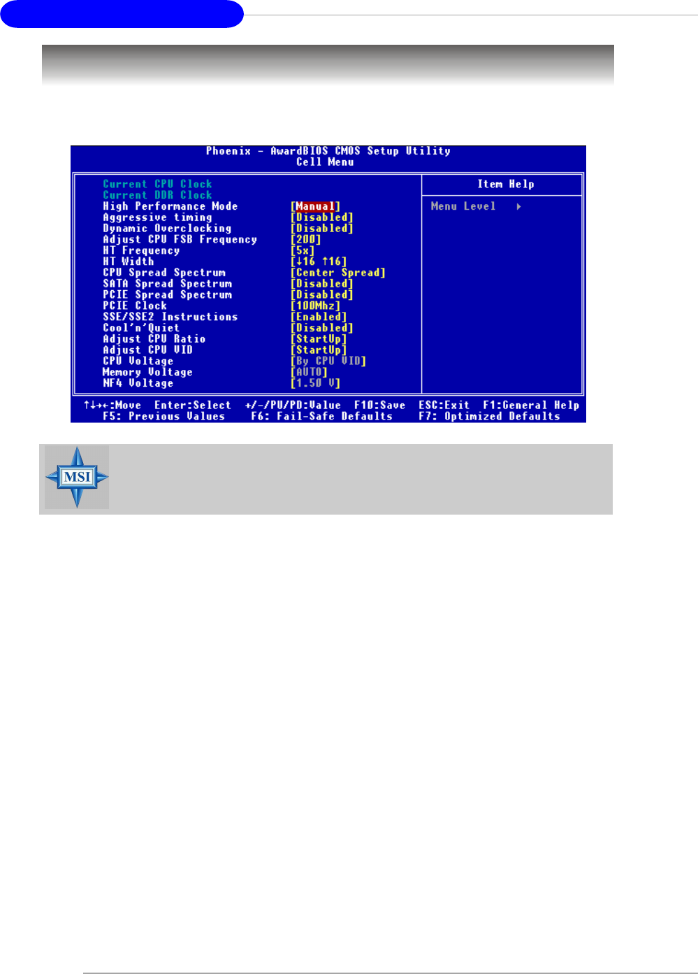
Cell Menu
The items in Cell Menu includes some important settings of CPU, AGP, DRAM and
overclocking functions.
Current CPU / DDR Clock
These two items show the current clocks of CPU & DDR. Read-only.
MSI Reminds You...
Change these settings only if you are familiar with the chipset.
High Performance Mode
This field allows you to select the DDR timing setting. Setting options: [Manual], [Optimized].
Aggressive timing
This item allows you to enable or disable the memory clock. When [Enabled] is selected,
the timing delay of memory will be shorten to increase the performance. Setting options:
[Enabled], [Disabled].

BIOS Setup
E-3-7
Dynamic Overclocking
Dynamic Overclocking Technology is the automatic overclocking function, included in
the MSITM’s newly developed CoreCellTM Technology. It is designed to detect the load
balance of CPU while running programs, and to adjust the best CPU frequency
automatically. When the motherboard detects CPU is running programs, it will speed up
CPU automatically to make the program run smoothly and faster. When the CPU is
temporarily suspending or staying in the low load balance, it will restore the default
settings instead. Usually the Dynamic Overclocking Technology will be powered only
when users' PC need to run huge amount of data like 3D games or the video process,
and the CPU frequency need to be boosted up to enhance the overall performance.
Setting options:
[Disabled] Disable Dynamic Overclocking function.
[Private] 1st level of overclocking, increasing the CPU frequency by 1%.
[Sergeant] 2nd level of overclocking, increasing the CPU frequency by 3%.
[Captain] 3rd level of overclocking, also the default value of "Load High
Performance Defaults", increasing the CPU frequency by 5%.
[Colonel] 4th level of overclocking, increasing the CPU frequency by 7%.
[General] 5th level of overclocking, increasing the CPU frequency by 9%.
[Commander] 6th level of overclocking, increasing the CPU frequency by 11%.
MSI Reminds You...
Even though the Dynamic Overclocking Technology is more stable
than manual overclocking, basically, it is still risky. We suggest user
to make sure that your CPU can afford to overclocking regularly first. If
you find the PC appears to be unstable or reboot incidentally, it's better
to disable the Dynamic Overclocking or to lower the level of overclocking
options. By the way, if you need to conduct overclocking manually, you
also need to disable the D.O.T Ranger first.
Adjust CPU FSB Frequency
This item allows you to select the CPU Front Side Bus clock frequency (in MHz). Select
the number between [200]~[400] for needed frequency.
HT Frequency
This setting specifies the maximum operating frequency of the link’s transmitter clock.
Setting options: [1x], [1.5x], [2x], [2.5x], [3x], [4x], [5x].
HT Width
This field allows you to set the HT Width between CPU & Chip.↑ mark means Chip to
CPU HT Width. And ↓ mark means CPU to Chip HT Width. Setting options: [ ↓ 8 ↑ 8],
[ ↓ 16 ↑ 8], [↓ 8 ↑16], [ ↓16 ↑16].
CPU Spread Spectrum
This setting is used to enable or disable the CPU Spread Spectrum feature. When
overclocking the CPU, always set it to [Disabled]. Setting options: [Center Spread],
[Disabled].

MS-7125 M-ATX Mainboard
E-3-8
SATA Spread Spectrum
This setting is used to enable or disable the SATA Spread Spectrum feature. Setting
options: [Disabled], [Down Spread].
PCIE Spread Spectrum
This setting is used to enable or disable the CPU Spread Spectrum feature. When
overclocking the CPU, always set it to [Disabled]. Setting options: [Disabled], [Down
Spread].
PCIE Clock
The system board designer selects whether the PCIE clock is tightly synchronized
with the CPU clock or is asynchronous. Setting options: [100MHz]~[145MHz].
SSE/ SSE2 Instructions
This setting disables/enables the SSE/SSE2 Instructions. The Streaming SIMD Exten-
sions (SSE) were introduced in the Pentium III processor. The SSE extensions consist
of a new set of instructions and a new set of registers. These instructions and
registers are designed to allow Single-Instruction Multiple-Data (SIMD) computations to
be made on single-precision floating-point numbers.
The Streaming SIMD Extensions 2 (SSE2) were introduced in the Pentium 4 and Intel
Xeon processors. They consist of a new set of instructions that operate on the XXM
and MXCSR registers and perform SIMD operations on double-precision floating-point
values and on integer values.Several of these new SSE/SSE2 instructions also oper-
ate in the MMX registers. Setting options: [Enabled], [Disabled].
Cool’n’Quiet control
This feature is especially designed for AMD Athlon processor, which provides a CPU
temperature detecting function to prevent your CPU’s from overheating due to the
heavy working loading. Setting options: [Disabled], [Enabled].

BIOS Setup
E-3-9
Adjust CPU Ratio
This item lets you adjust the CPU ratio. Setting to [Startup] enables the CPU running at
the fastest speed which is detected by system. Setting options are: [Startup], [x4]~
[x12].
Adjust CPU VID
This item lets you adjust the CPU VID. Setting to [Startup] enables the CPU running at the
default VID which is detected by system. Setting options are: [Startup], [0.825V], [0.
850V],[0.875V],~, [1.550V].
CPU Voltage
This feature allows you to trim the voltage of CPU. Setting options are: [By CPU VID],
[Over VID 3.3%], [Over VID 5.0%],[Over VID 8.3%].
Memory Voltage
Adjusting the DDR voltage can increase the DDR speed. Any changes made to this
setting may cause a stability issue, so changing the DDR voltage for long-term
purpose is NOT recommended. Setting options are: [Auto], [2.50V]~[2.85V].
NF4 Voltage
NV4 voltage is adjustable in the field. Setting options are: [1.50V]~[1.85V].
MSI Reminds You...
The settings shown in different color in CPU Voltage, Memory Volt-
age and NF4 Voltage help to verify if your setting is proper for your
system.
Gray: Default setting.
Yellow: High performance setting.
Red: Not recommended setting and the system may be
unstable.
Changing CPU VID, CPU Voltage, Memory Voltage and NF4 Volt-
age may result in the instability of the system; therefore, it is NOT
recommended to change the default setting for long-term usage.

F-1
Manuel d’Utilisation
K8N Neo4 Platinum
(MS-7125 v1.X)
Carte Mère ATX
Français
F-1

F-2
Carte Mère ATX MS-7125

F-3
Manuel d’Utilisation
Chapter 1. Getting
Started
K8N Neo4 Platinum
Manuel d’utilisation
Féliciation vous venez d’acheter une carte mèreATX K8N
Neo4 Platinum (MS-7125) v1.X. La K8N Neo4 Platinum est basée
sur le chipset nVIDIA® nForce4 offrant des performances
importantes. Elle fonctionne avec les processeurs AMD® K8 Athlon
64FX / Athlon 64 et offre un système hautement performant tant
pour les particuliers que pour les professionnels.

F-4
Carte Mère ATX MS-7125
Spécificités de la Carte
CPU
hProcesseur AMD K8 Socket-939 pour Athlon 64 FX / Athlon 64
hJusqu’à Athlon64 3500+, 3800+ ou supérieur
(Pour une mise à jour sur les dernières informations CPU, veuillez visiter : http://
www.msi.com.tw/program/products/mainboard/mbd/pro_mbd_cpu_support.php)
Chipset
hnVIDIA nForce4 Ultra
- Lien HyperTransport avec le CPU AMD Athlon 64/Athlon 64 FX CPU
- HyperTransport support une vitesse maxi de 1GHz (2000MT/s)
- Supporte l’interface PCI Express x16/x1/x2
- Deux contrôleurs SATA indépendants pour quatre disques
- Contrôleurs Dual Fast ATA-133 IDE
- IEEE802.3 nVIDIA MAC pour 1000BASE-T
Mémoire Principale
hSupport du double canal, 8 banques de mémoire DDR 266/333/400 184 broches
hSupporte un maximum de mémoire de 4GB
hSupporte le 2.5v DDR SDRAM DIMM
(Pour une mise à jour sur les modules de mémoire, veuillez vivister : http://www.msi.
com.tw/program/products/mainboard/mbd/pro_mbd_trp_list.php.)
Slots
hUn slot PCI Express x16 slot (supportant les spec. PCI Express Bus v1.0a)
hUn slot PCI Express x1 slots (supportant les spec. PCI Express Bus v1.0a)
hUn slot PCI Express x4 (supportant PCI Express x2 uniquement )
hQuatre slots 32-bit Master PCI Bus, slot orange réservé pour une carte de
commuinication.
hSupporte l’interface 3.3V/5V PCI bus
IDE Intégré
hUn contrôleur IDE sur le chipset nVIDIA® nForce4 Ultra procurant IDE HDD/CD-
ROM avec PIO, Bus Master et les modes opératoires Ultra DMA 66/100/133
hCan connect up to 4 IDE devices
SATA Intégré
hSuporte NV RAID 4 ports SATA (SATA1-4). Le taux de transfert du SATAII est de
300MB/s maximum.
hSilicon Image’s SATARAID5TM supportant 4 autres ports SATA (SATA5-8). Le taux
de transfert SATA est de 150MB/s. (Option)

F-5
Manuel d’Utilisation
Interface USB
h10 ports USB
- Contrôllé par le chipset nForce4 Ultra
- 4 ports à l’arrière, 6 ports via bracket externe
NV RAID (Logiciel)
hSupporte jusqu’à 4 SATA et 4 ATA133 disques durs
- RAID 0 or 1, 0+1, JBOD sont supportés
- Fonction RAID disponible pour les disques durs PATA+SATA
Silicon Image’s SATARAID5TM (logiciel) (Option)
hRAID 0 ou 1, RAID5, RAID10, et groupes JBOD sont supportés
hSupporte jusqu’à 4 SATA connecté à un simple connecteur
Dual LAN (Optional)
hSupporte dual LAN jack
- 1er LAN supportant 10/100/1000 Fast Ethernet par Marvell 88E1111
- 2ème LAN supportant 10/100/1000 Fast Ethernet par Marvell 88E8053
IEEE 1394 (Option)
hSupporte jusqu’à 2 ports 1394 (panneau arrière x 1, broches x 1). Taux de transfert
jusqu’à 400Mbps
Audio
hChip intégré Realtek ALC850
- Direct Sound AC97 audio
- 7.1 canaux en sortie
Périphériques Intégrés
hLes périphériques intégrés sont :
- 1 port floppy supportant 1 FDD avec 360K, 720K, 1.2M, 1.44M et 2.88Mbytes
- 1 port série
- 1 port parallèle supportant les modes SPP/EPP/ECP
- 1 Audio jack(5-in-1), coaxial/fiber SPDIF out
- 1 jeu de broches IrDA
- 1 jeu de broches CD-In
- 1 jeu de broches D-Bracket2
- 2 ports IEEE1394 (Arrière * 1 / Façade * 1)(Option)
- 10 ports USB1.1/2.0 (Arrière * 4 / Façade * 6)

F-6
Carte Mère ATX MS-7125
BIOS
hLe BIOS est “Plug & Play” ce qui permet nue détection automatique des périphériques
et/ou cartes d’extensions.
hLa carte mère procure une interface DMI (Desktop Management Interface) qui
permet d’enregistrer les spécificités de la carte.
hSupporte le boot à partir : LAN, matériel USB 1.1 & 2.0, et disque dur SATA.
Dimension
hFormat ATX (30.4 cm X 24.4 cm)
Montage
h9 trous de montage
MSI Vous Rappelle...
1. nVidia nForce4 uniquement disponible pour Windows 2000 et Win-
dows XP.
2. Pour créer un boot RAID sous Microsoft’s Windows 2000 il faut
utiliser le Service Pack 4 (SP4). Vous ne pouvez installer le système
d’exploitation sans avoir ce CD. Pour le créer, veuillez vous reporter
au site :
http://www.microsoft.com/windows2000/downloads/
servicepacks/sp4/HFdeploy.htm
F-7
Manuel d’Utilisation
Schéma de la Carte
Carte Mère ATX K8N Neo4 Platinum (MS-7125 v1.X) ATX
CPUFAN1
NBFAN1
S1W
SFAN2
JPW1
FDD1
SATA3
SATA5 SATA8
SATA6 SATA7
SATA4
SATA1
SATA2
JCD1
T:
M:
B:
Line-In
Line-Out
Mic
T: R S - O u t
M:CS
B:SPDIF Out
-Out
T: L A N j ac k
B: USB ports
(Optional)
T: L A N j ac k
B: USB ports
(Optional)
Winbond
W83627THF
Silic on Image
SATALink
Sil3114CT 176
(Optional)
VIA
VT6307
(Optional)
88E1111-RCJ
(Optional)
BATT
+
DIMM 1
SFAN1
DIMM 3
DIMM 2
DIMM 4
AT X1
PCI Slot 3
PCI Slot 2
PCI Slot 1
PCI _E3
PCI _E2
PCI _E1
IDE 2
IDE 1
JFP1
JDB1
JFP2
JIR1JIR1
JCI1
JLPC1
JAUD1 JUSB2 JU SB3
JUSB1
J1394_1
(Optional)
Top : Parallel Port
Bottom:
COM Port
1394 Port (Optional)
SPDIF OUT
To p : m o u s e
Bottom: keyboard
MSI
CoreCell
BIOS
Codec
PCI Slot 4
88E8053-NNC
(Optional)
NForce4
Ultra
(Optional)
7
126
5
6
1
15
24
4
13
4
48
3
11
9
1014
17
16
F-8
Carte Mère ATX MS-7125
1. Connecteur d’alimentation ATX 24 broches : ATX1. Ce connecteur vous
permet de vous connecter à une alimentation ATX.
2. Connecteur d’alimentation ATX 12V : JPW1. Ce connecteur d’alimentation
est utilisé pour alimenter le CPU.
3. Connecteur Floppy Disk Drive : FDD1. La carte mère procure un connecteur
floppy disk drive standard supportant les floppy disk drives de 360K,
720K, 1.2M, 1.44M et 2.88M.
4. Connecteur d’alimentation du ventilateur: CPUFAN1/SFAN1/SFAN2/NBFAN1.
The CPUFAN1 (ventilateur de processeur), SFAN1 (ventilateur de système
1), SFAN2 (ventilateur de système 2) et NBFAN1 (ventilateur de chipset
NorthBridge ) supportent le +12V.
5. Connecteurs de disques durs ATA 133 : IDE1 & IDE2. Cette carte mère
possède un contrôleur 32-bit Enhanced PCI IDE et Ultra DMA 66/100/133
qui procure les fonctions PIO mode 0~4, Bus Master et Ultra DMA 66/100/
133.
6. Connecteurs Serial ATA/Serial ATA RAID contrôlés par
nForce4 Ultra: SATA1 / SATA2 / SATA3 / SATA4; Connecteurs Serial ATA/
Serial ATA RAID contrôlés par Silicon Image’s SATARAID5TM:
SATA5 / SATA6 / SATA7 / SATA8 (Optionnel). Le Southbridge de cette
carte mère est nForce4 Ultra qui supporte quatre connecteurs serial ATA
SATA1~SATA4. Silicon Image’s SATARAID5TM supporte quatre autres
connecteurs serial ATA SATA5~SATA8. SATA1~SATA8 sont des ports
d’interface serial ATA haute vitesse. Chacun supporte un taux de
données serial ATA de 300MB/s(SATA1-4)/150 MB/s(SATA5-8).
7. Connecteurs Front Panel : JFP1/JFP2. La carte mère procure deux
connecteurs two front panel pour les connections éléctriques de
l’interrupteur en façade et des LEDs
8. Connecteur CD-In : JCD1. Le connecteur est destiné aux branchements
audio du CD-ROM..
9. Connecteur Chassis Intrusion Switch : JCI1. Ce connecteur est connecté
à un chassis switch 2 broches. Si le chassis est ouvert, le système
enregistrera la statut
10. Connecteur D-Bracket™ 2 : JDB1. La carte mère procure un connecteur
JDB1 permettant de se connecter au D-BracketTM 2. D-Bracket™ 2 est un
bracket USB qui supporte les specificités USB1.1 & 2.0
JFP1
19
10
2
Power
LED Power
Switch
Reset
Switch
HDD
LED
Power
LED
Speaker
1
27
8
JFP2

F-9
Manuel d’Utilisation
11. Connecteur Infra rouge IrDA : JIR1. Ce connecteur pemret la connection au
module infrarouge IrDA. Vous devez configurer les paramètres du BIOS pour
utiliser la fonction IR.
12.Connecteurs Front USB: JUSB1, JUSB2 & JUSB3. Cette carte mère procure trois
connecteurs standards USB2.0: JUSB1, JUSB2 & JUSB3.
13. ConnecteursIEEE1394 (Optionnel): J1394_1. la carte mère procure un connecteur
1394 qui pemrmettent une connection aux ports IEEE 1394 par un bracket externel
IEEE1394 (optionnel).
14. Connecteur Front Panel Audio : JAUD1. Ce connecteur front panel audio permet
de vous connecter au front panel audio et est compatible avec with Intel® Front
Panel I/O Connectivity Design Guide.
15. Bouton Clear CMOS: SW1. Le CMOS RAM intégré est alimenté par une batteie
extérieur qui garde les données de configuration du système. Avec le CMOS
RAM, le système peut automatiquement booter avec les paramètres personnalisés
du BIOS chaque fois que le PC est allumé.
16. PCI (Peripheral Component Interconnect) Slots. Les slots PCI Express possède
une large bande passante. Vous pouvez insérer des cartes d’expansion selon
vos besoins. Lorsque vous ajoutez ou enlever une carte d’expansion, assurez-
vous que le PC n’est pas relié au secteur. Pour la configuration des cartes PCI,
veuillez vous reporter au manuelm fournit avec votre matériel. ilo est parfois
nécessaire de configurer le BIOS pour que la carte PCI soit fonctionnelle.
Le slot PCI orange (PCI5) fonctionne aussi comme slot de communication, ce
qui vous permet d’y insérer une carte de communication pour le Wifi (réseau
sans fil) par exemple.
17. Slots PCI (Peripheral Component Interconnect) Express. Les slots PCI Express
possèdent une large bande passante, supportent les plateformes desktop AMD
haute performances utilisant le processeur AMD ainsi que les avantages de
cette plateforme.
MSI Vous Rappelle...
A Noter que les broches VCC et GND doivent être correctement
connecter. afin d’éviter tout endommagement.

F-10
Carte Mère ATX MS-7125
Central Processing Unit: CPU
La carte mčre supporte les processeurs AMD® Athlon64. La carte utilise un
socket appelé Socket-939. Lors de l’installation du CPU, assurez-vous de bien in-
staller un dissipateur + ventilateur afin d’éviter la surchauffe. Si vous ne savez pas
le modèle qu’il vous faut, il est recommandé de prendre contact avec
votre revendeur.
Pour une mise à jour sur les informations relatives au CPU, veuillez visiter http:/
/www.msi.com.tw/program/products/mainboard/mbd/pro_mbd_cpu_support.php.
MSI Vous Rappelle...
Surchauffe
Une surchauffe peut sérieusement endommager le CPU et le système,
assurez vous toujours que le système de reffroidissement fonctionne
correctement pour protéger le CPU d’une surchauffe.
Remplacer le CPU
Avant de remplacer le CPU, éteignez toujours l’alimentation ATX ou
débranchez la prise pour assurer la sécurité du CPU.
Overclocking
Cette carte mère a été créée pour supporter l’overclocking. Assurez
vous que vos composants sont capables de tolérer de tels réglages,
avant d’overclocker le système. Tout essais au delà des spécifications
des produits n’est pas recommandé. Nous ne garantissons pas les
dommages causés par une mauvaises opération ou au delà des
spécifications du produit.

F-11
Manuel d’Utilisation
Installation du CPU AMD Athlon64
Quand vous installez votre CPU, assurez-vous que le CPU possède un système
de refroidissement pour prévenir les surchauffes.
1. Détacher la protection
2.Retourner la carte mère et installer la
plaque métallique
3. Retourner la carte mère et localiser
les deux trous de vis sur la carte
mère.
4. Aligner le méchanisme de rétention
et la plaque métallique.
Fixer le méchanisme de rétention et
la plaque métallique avec les vis.
retention mechanism
F-12
Carte Mère ATX MS-7125
6. Localiser le levier de fixation et le
crochet de sécurité
Relever le levier.
5. Positionner le ventilateur sur le
méchanisme de rétention.
Attacher un coté puis l’autre en
s’assurant que l’ensemble est bien
sécurisé.
7. Abaisser le levier
8. S’assurer que le crochet est sécurisé
( avec le méchanisme de rétention).
Safety Hook
Fixed Bolt
Fixed Lever
9.Connectez le câble d’alimentation sur
le connecteur de la carte mère prévu
à cet effet
MSI Vous Rapelle...
Lorsque vous déconnectez le crochet, il est nécessaire de garder un
oeil sur vos doigts car une fois le crochet déconnecté, celui-ci reprend
sa position initial du à son ressort.
F-13
Manuel d’Utilisation
Procédure d’installation du CPU pour Socket 939
1. Veuillez éteindre et débrancher
votr e PC avant l’installation du
CPU
2. Tirez le levier vers le haut.
Assurez-vous que celui-ci est
bien en position ouverte maxi-
mum (angle de 90°)
3. Repérez la flèche dorée. La
flèche dorée doit se trouver
comme indiqué sur le dessin. Le
CPU ne peut être installer que
dans un seul sens.
4. Si le CPU est correctement
installé alors les broches ne sont
plus visibles. Une mauvaise in-
stallation pourrait entraîner des
dommages vis-à-vis de la carte
mère
5. Appuyez sur le CPU pendant que
vous abaissez le levier. Il faut
toujours exercer une pression
sur le CPU pour éviter que ce
dernier ne soit pas bien fixé une
fois le levier abaissé.
Open Lever
90 degree
Sliding
Plate
Gold arrow
Gold arrow
Gold arrow
Correct CPU placement
O
F-14
Carte Mère ATX MS-7125
Mémoire
DIMM1~4
(de gauche à droite)
La carte mère procure 4 slots DDR DIMM (Double In-Line Memory Module) (184
broches) et supporte jusqu’à 4GB de mémoire. Vous pouvez installer les modules
DDR 266/333/400 sur les slotsDDR DIMM (DIMM 1~4).
Pour les dernières mises à jours sur les modules de mémoires, veuillez visiter le site
suivant : http://www.msi.com.tw/program/products/mainboard/mbd/pro_mbd_trp_list.
php.
DIMM Module Combination
Installez au moins un module DIMM sur les slots. Chaque slot DIMM supporte
une taille maximum d’ 1GB. Merci de noter que chaque DIMM fonctionnera
respectivement avec le single channell DDR mais certaines règles permettent d’utiliser
le dual channel DDR(merci de vous reporter au tavleau ci-contre). Vous pouvez
installer des modules simples ou doubles faces selon vos besoins. Vous pouvez
installer des mémoires de modules de différent type et de densité sur les différents
canaux DDR DIMMs. Les modules de mémoire de même type et densité sont requis
lors de l’utilisation dual-channel DDR, sinon une instabilité peut apparaître.
Merci de vous reférer au tableau suivant pour les détails sur le dual channel DDR.
D’autres combinaisons non référencées peuvent fonctionner en single channel DDR
Introduction à la DDR SDRAM
La DDR SDRAM est similaire à la SDRAM conventionnelle mais double le taux de
transfert de données deux fois par cycle. Il utilise le 2.5v contrairement au 3.3v de la
SDR SDRAM.
Les modules de DDR possèdent 184 broches, contre 168 pour les modules
DIMM utilisé par SDR SDRAM. C’est une solution idéale pour les PC haute performance,
de travail et les serveurs.
F-15
Manuel d’Utilisation
nstallation des modules DDR
1. La DDR DIMM ne posséde qu’une encoche en son centre. Le mod
ule ne peut être monté que dans le bon sens
2. Insérez le module de mémoire DIMM verticalement sur le slot. Puis
appuyez dessus
3. Le clip en plastique situé de chaque coté du module va se fermer
automatiquement
Combinaison des modules DIMM
Installez au moins un module DIMM sur les slots. Vous pouvez installer des modules
simples ou doubles faces selon vos besoins.
Les modules de mémoire peuvent être installés selon les combinaisons suivantes:
S: Single Side D: Double Side
Slot Module de Mémoire Mémoire Totale
DDR 2
(Bank 2 & 3) S/D 64MB~1GB
Maximum System Memory Supported 64MB~2GB
DDR 1
(Bank 0 & 1) S/D 64MB~1GB
Volt Encoche
MSI Vous Rappelle...
La marque dorée doit ą peine źtre visible lorsque le module est
correctement installé.

F-16
Carte Mère ATX MS-7125
Allumez votre ordinateur, le système lance le processus de POST (Power On Self
Test). Quand le message ci-dessous apparaît à l’écran, appuyez sur le bouton <DEL>
pour entrer dans le setup.
Press DEL to enter SETUP
Si le message disparaît avant que vous ne puissiez entrer dans le setup, redémarrez
votre ordinateur en appuyant sur le bouton RESET. Vous pouvez aussi utiliser
simultanément la combinaison de touches : <Ctrl>, <Alt>, et <Delete>. .
Setup du BIOS
Control Keys
<↑>Se déplacer au champ précédent.
<↓>Se déplacer au champ suivant.
<←>Se déplacer au champ sur la gauche.
<→>Se déplacer au champ sur la droit.
<Enter> Séléctoinner le champ.
<Esc> Quitter ou retourner au menu principal.
<+/PU> Augmente la valeur numérique ou change l’option.
<-/PD> Diminue la valeur numérique ou change l’option.
<F5> Restaure la précédente valeur du CMOS
<F7> Charge les valeurs optimisées par défaut
<F10> Sauve toute les mofications du CMOS et quitte.
F-17
Manuel d’Utilisation
Menu Principal
Standard CMOS Features
Cette fonction permet le paramétrage des éléments standards du BIOS.
Advanced BIOS Features
Cette fonction permet de paramétrer des éléments avancés du Bios.
Advanced Chipset Features
Cette option vous permet de paramétrer les éléments relatifs au registre
du chipset, permettant ainsi d’optimiser les performances de votre système.
Integrated Peripherals
Utilisez ce menu pour changer les choix relatifs aux périphériques intégrés.
Power Management Setup
Utilisez ce menu pour appliquer vos choix en ce qui concerne le power management
PNP/PCI Configurations
Apparaīt si votre systčme supporte PNP/PCI.
H/W Monitor
Voir les statuts des CPU, ventilateur, et alarme système.
Cell Menu
Utilisez ce menu pour spécifier vos paramètres pour la fréquence et le voltage des
CPU/DRAM/AGP.
Une fois entré dans le BIOS Phoenix-Award® CMOS Setup Utility, Le menu
apparaît à l’écran. Le Menu permet de sélectionner douze fonctions et deux choix de
choix de sortie de l’utilitaire. Utilisez les flèches pour vous diriger et utilisez la touche
ENTREE pour sélectionner un élément ou entrer dans le sous-menu.

F-18
Carte Mère ATX MS-7125
Load Optimized Defaults
Charge les paramètres optimum du BIOS sans affecter la stabilité du système.
BIOS Setting Password
Utilisez ce menu pour entrer un mot de passe du BIOS
Save & Exit Setup
Les modifications sont enregistrées dans le CMOS avant la sortie du setup
Exit Without Saving
Les modifications sont abandonnées avant la sorti du setup

F-19
Manuel d’Utilisation
Cell Menu
Vous pouvez dans ce menu gérer d’importantes fonctions du CPU, AGP, DRAM et
d’overclocking.
MSI vous rapelle...
Ne changer ces paramètres que si vous maîtrisez bien ce chipset.
Current CPU / DDR Clock
Vitesse d’horloge des CPU & DDR. Lecture seule.
High Performance Mode
Sélectionner les paramètres the CPU/FSB. Options: [Manual], [Optimized]. Lorsque
[Optimized] est sélectionné, le système utilisera des paramètres d’overclocking pour
le CPU/FSB. Sélectionner [Manual] pour le mode normal CPU/FSB.
Aggressive timing
Cet élément permet d’activer/désactiver l’horloge mémoire. Quiand [Enabled] est
selectionné, le temps d’attente de la mémoire sera diminué afin d’accroître les
performances. Les paramètres sont : [Enabled], [Disabled].

F-20
Carte Mère ATX MS-7125
Dynamic Overclocking
Le DOT (Dynamic Overclocking Technology) est une fonction overclocking automatique
inclut dans la nouvelle technologie CoreCellTM développée par MSITM. Déstiné à détecter
la charge de travail du CPU lors de l’utilisation de programmes, le DOT permet
d’augmenter la fréquence du CPU automatiquement afin que le programme soit utilisé
dans les meilleures conditions. Quand le CPU ne travaille pas ou que son activité est
faible alors les paramètres par défaut sont utilisés. En règle général, le DOT se met en
action lorsque la demande en puissance est importante comme lorsque vous utilisez
des jeux 3D. Les options sont :
[Disabled] Désactive la fonction DOT.
[Private] 1er niveau d’overclocking, augmentant la fréquence CPU de 1%.
[Sergeant] 2ème niveau d’overclocking, augmentant la fréquence CPU de
3%.
[Captain] 3ème niveau d’overclocking ( "Load High Performance Defaults")
augmentant la fréquence CPU de 5%.
[Colonel] 4ème niveau d’overclocking, augmentant la fréquence CPU de
7%.
[General] 5ème niveau d’overclocking, augmentant la fréquence CPU de
9%.
Commander] 6ème niveau d’overclocking, augmentant la fréquence CPU de
11%
MSI Vous Rappelle...
Męme si le DOT est plus stable que l’overclocking manuel, cela
reste risqué. Nous vous suggérons de faire un overclocking
Adjust CPU FSB Frequency
Cet élément vous permet de sélectionner la fréquence du FSB du CPU (en MHz).
Choisir un nombre entre [200]~[300] pour la fréquence voulue.
HT Frequency
Ce paramètre spécifie la fréquence maximale d’exploitation. Les options: [1x], [2x],
[3x], [4x], [5x]
HT Width
Ce champs vous permet de paramétrer l’HT Width entre CPU & Chip.- mark means
Chip to CPU HT Width. Options: [ 8 - 8], [16 - 8], [8 -16], [16 -16].
CPU Spread Spectrum
Ce paramètre permet d’activer/désactiver la fonction de Spread Spectrum CPU.
Lorsque vous faites de l’overclocking sur le FSB, veuillez toujours sélectionner
[Disabled]. Les options : [Center Spread], [Disabled].

F-21
Manuel d’Utilisation
SATA Spread Spectrum
Ce paramètre permet d’activer/désactiver la fonction de Spread Spectrum SATA. Les
options: [Disabled], [Down Spread].
PCIE Spread Spectrum
Ce paramètre permet d’activer/désactiver la fonction de Spread Spectrum CPU.
Lorsque vous faites de l’overclocking sur le FSB, veuillez toujours sélectionner
[Disabled]. Les options : Disabled], [Down Spread].
PCIE Clock
Ce paramètre détermine la fréquence d’horloge des slots PCI Expresss. Setting options:
[100MHz] ~ [145MHz].
Instructions SSE/SSE2
Cet élément active/désactive les instructions SSE/SSE2. Le SSE (Streaming SIMD
Extensions) est introduit avec les processeurs Pentium III. Les extensions SSE con-
sistent en un nouveau jeu d’instructions pour le registre. Ces fonctions sont
développées pour des instructions simples ou multiples (SIMD).
Les SSE2 (Streaming SIMD Extensions 2) sont introduites avec les processeurs
Pentium 4 et Intel Xeon. Elles consistent en de nouveaux jeux d’instructions qui
fonctionnent avec les registres XXM et MXCSR pour améliorer les performances
SIMD des opérations en virgules flottantes et en valeurs intégrées. Plusieurs de ces
nouvelles instructions fonctionnent avec le registre MMX. Options: [Enabled],
[Disabled].
Cool’n’Quiet control
Cette fonction est exclusivement réservée aux processeurs AMD Athlon, elle pro-
cure une fonction de détection de la température du CPU permettant ainsi d’éviter la
surchauffe. Les options: [Disabled], [Auto].

F-22
Carte Mère ATX MS-7125
Adjust CPU Ratio
Cet élément vous permet d’ajuster le ratio du CPU. En mode [Startup] cela permet au
CPU de fonctionner plus rapidement. Les options : [Startup], [x4]~[x16].
Adjust CPU VID
Ce champs vous permet d’ajuster le CPU VID. En position [Startup] cela permet au
CPU de fonctionner avec le VID par défaut détecter par le système. Paramètres:
[Startup], [1.550V] ~ [0.825V].
CPU Voltage
Ce champs vous permet d’équilibrer le voltage du CPU. Options: [By CPU VID], [Over
VID 3.3%], [Over VID 5.0%],[Over VID 8.3%].
Memory Voltage
Modifier le voltage DDR peut augmenter la vitesse de la DDR. Tous les changements
peuvent entraîner une instabilité, par conséquent l’utilisation d’un paramètre modifié e
doit pas se faire de façon défintive mais temporaire.
NF4 Voltage
NF4 voltage est ajustable dans ce champs.
MSI Vous Rappelle...
Les paramètres de couleurs différentes pour CPU Voltage, Memory
Voltage et AGP Voltage vous aident à vérifier si les paramètres pour
votre système sont correctes.
Gris: Paramètres par défaut.
Jaune: Paramètres hautes performances.
Rouge: Paramètres non recommandés et système instable.
Changer le CPU Voltage, Memory Voltage et AGP Voltage peut
entraîner une instabilité, c’est pourquoi nous ne recommandons pas
de changer ces paramètres pour une utilisation prolongée.

G-1
Benutzerhandbuch
K8N Neo4 Platinum
(MS-7125 V1.X)
ATX Mainboard.
Deutsch
G-1

G-2
MS-7125 ATX Mainboard

G-3
Benutzerhandbuch
Chapter 1. Getting
Started
K8N Neo4 Platinum
Benutzerhandbuch
Danke, dass Sie das K8N Neo4 Platinum (MS-7125) V1.X
ATX Mainboard gewählt haben. Das K8N Neo4 Platinum Mainboard
basiert auf dem nVIDIA® nForce™4 Ultra Chipsatz und ermöglicht
somit ein optimales und effizientes System. Entworfen, um den
hochentwickelten AMD® K8 Athlon 64 FX / Athlon 64 Prozessor
aufzunehmen, stellt das Mainboard K8N Neo4 Platinu die ideale
Lösung zum Aufbau eines professionellen Hochleistungs-
desktopsystems dar.

G-4
MS-7125 ATX Mainboard
Mainboard Spezifikationen
CPU
hUnterstützt den Sockel-939 für AMD K8 Athlon 64 FX / Athlon 64 (Sockel939)
Prozessoren
hUnterstützt Prozessoren bis hin zum Athlon64 3500+, 3800+, oder höher
(Die neuesten Informationen zu unterstützten Prozessoren finden Sie unter http://
www.msi.com.tw/program/products/mainboard/mbd/pro_mbd_cpu_support.php)
Chipsatz
hnVIDIA nForce4 Ultra
- HyperTransport Link zur AMD Athlon 64/Athlon 64 FX CPU
- HyperTransport unterstützt Geschwindigkeiten bis hin zu 1GHz (2000MT/s)
- Bietet PCI Express x16/x1/x2 Schnittstellen
- Zwei unabhängige SATA Kontroller, für vier Laufwerke
- Zwei Fast ATA-133 IDE Kontroller
- IEEE802.3 nVIDIA MAC für 1000BASE-T
Hauptspeicher
hUnterstützt Zweikanal DDR 266/333/400, auf acht Speicherbänken für vier 184-
Pin DDR DIMMs
hUnterstützt einen maximalen Speicherausbau von bis zu 4GB
hUnterstützt 2,5V DDR SDRAM DIMM
(Um den letzten Stand bezüglich der unterstützten Speichermodule zu erhalten,
besuchen Sie bitte http://www.msi.com.tw/program/products/mainboard/mbd/
pro_mbd_trp_list.php.)
Steckplätze
hEin PCI Express x16 Sockel (erfüllt die PCI Express Bus Spezifikation V1.0a)
hEin PCI Express x1 Sockel (erfüllt die PCI Express Bus Spezifikation V1.0a)
hEin PCI Express x4 Sockel (unterstützt nur PCI Express x2 Karten )
hVier 32-bit Master PCI Bus Slots, einschließlich eines orangefarbenen, der auch
als Kommunicationssockel dienen kann
hUnterstützt 3,3V/5V PCI- Bus
Onboard IDE
hEin im nVIDIA® nForce4 Ultra Chipsatz enthaltener IDE Kontroller bietet für den
Festplatten- und CD-ROM-Zugriff PIO, Bus Mastering und Betrieb mit Ultra DMA
66/100/133
hBis zu vier IDE Geräte anschließbar
Onboard SATA
hNV RAID unterstützt 4 SATA II Anschlüsse (SATA1-4), mit einer
Datenübertragunsrate von bis zu 300 MB/s.
hSilicon Image’s SATARAID5TM unterstützt weitere 4 SATA Ports(SATA5-8), mit
einer Datenübertragunsrate von bis zu 150 MB/s. (Optional)

G-5
Benutzerhandbuch
USB Schnittstellen
h10 USB Anschlüsse
- Kontrolliert durch den nForce4 Ultra Chipsatz
- 4 Anschlüsse im hinteren Ein-/Ausgabebereich, 6 Anschlüsse über ein externes
Slotblech
NV RAID (Software)
hUnterstützt bus zu 4 SATA und 4 ATA133 Festplatten
- Bietet RAID 0 oder 1, 0+1, sowie JBOD
- RAID Funktionalität verfügbar für PATA+SATA Festplatten
Silicon Image’s SATARAID5TM (Software) (Optional)
hUnterstützt RAID 0 oder 1, RAID5, RAID10, und JBOD Gruppierungen (ohne RAID-
Funktionalität)
hUnterstützt bis zu 4 SATA Geräte an einem einzelnen Kontroller
Dual LAN (Optional)
hUnterstütz zwei LAN Buchsen
- 1ste LAN unterstützt 10/100/1000 Fast Etherneth durch den Marvell 88E1111
- 2te LAN unterstützt 10/100/1000 Fast Ethernet durch den Marvell 88E8053
IEEE 1394 (Optional)
hUnterstützt bis zu zwei 1394 Ports (1 am hinteren Anschlusspaneel, 1 als Stifblock
auf dem Mainboard). Übertragunsrate von bis zu 400Mbps
Audio
hIn den Chip integriert mit Realtek ALC850
- Direct Sound AC97 Audio Lösung
- 7.1 Kanal Ausgabet
Peripherieanschlüsse onboard
hhierzu gehören:
- 1 Anschluss für 1 Diskettenlaufwerk mit 360 KB, 720 KB, 1,2 MB, 1,44 MB oder
2,88 MB.
- 1 Serielle Schnittstelle
- 1 Parallele Schnittstelle, die die Betriebsmodi SPP/EPP/ECP unterstützt.
- 1 Audio Buchse(5-in-1), koaxial/Glasfaser SPDIF Ausgang
- 1 IrDA Stiftleiste
- 1 CD-Eingang als Stiftleiste
- 1 D-Bracket 2 Stiftleistenanschluss
- 2 IEEE 1394 (1 hintere / 1 vordere)(Optional)
- 10 USB1.1/2.0 Anschlüsse (4 hintere / 6 vordere)

G-6
MS-7125 ATX Mainboard
BIOS
h Das Mainboard- BIOS verfügt über “Plug & Play”- Funktionalität, mit der
angeschlossene Peripheriegeräte und Erweiterungskarten automatisch erkannt
werden.
hDas Mainboard stellt ein Desktop - Management - Interface (DMI) zur Verfügung,
welches automatisch die Spezifikationen Ihres Mainboards aufzeichnet.
hUnterstützt Systemstart über LAN, von USB 1.1 und 2.0 Geräten und SATA
Festplatte.
Abmessungen
hATX Form Faktor (30,4 cm X 24,4 cm)
Montage
h9 Montagebohrungen
MSI weist darauf hin ...
1. Derzeit steht der nVidia nForce4 Systemtreiber nur für Windows
2000 und Windows XP zur Verfügung.
2. Um ein bootfähiges RAID Laufwerk unter Windows 2000 zu erzeugen,
wird Microsoft’s Windows 2000 Service Pack 4 (SP4) benötigt. Da
der Endanwender nicht ohne SP4 booten kann, muss eine kombinierte
Installations- CD erstellt werden, bevor der Versuch unternommen
werden kann, das Betriebssystem auf ein bootfähiges RAID Laufwerk
zu installieren.
Entnehmen Sie bitte folgender Website, wie Sie eine kombinierte
Installations- CD erstellen:
http://www.microsoft.com/windows2000/downloads/
servicepacks/sp4/HFdeploy.htm
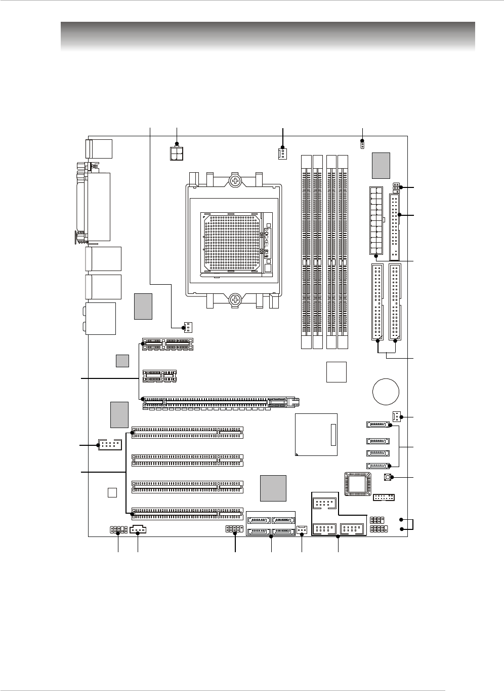
G-7
Benutzerhandbuch
Mainboard Layout
K8N Neo4 Platinum (MS-7125 V1.X) ATX Mainboard
CPUFAN1
NBFAN1
S1W
SFAN2
JPW1
FDD1
SATA3
SATA5 SATA8
SATA6 SATA7
SATA4
SATA1
SATA2
JCD1
:
M:
:
O Line-In
Line-Out
UMic
:RS-Out
:CS
:SPDIF Out
O
M-Out
U
O Buchse (Optional)
U: LAN
: USB ports
O Buchse (Optional)
UP
: LAN
: USB orts
Winbond
W83627THF
Silicon Image
SATALink
Sil3114CT176
(Optional)
VIA
VT6307
(Optional)
88E1111-RCJ
(Optional)
BATT
+
DIMM 1
SFAN1
DIMM 3
DIMM 2
DIMM 4
ATX1
PCI Slot 3
PCI Slot 2
PCI Slot 1
PCI _E3
PCI _E2
PCI _E1
IDE 2
IDE 1
JFP1
JDB1
JFP2
JIR1JIR1
JCI1
JLPC1
JAUD1 JUSB2 JUSB3
JUSB1
J1394_1
(Optional)
Oben : Parallele Schnittstelle
Unten:
COM Port
1394 Port (Optional)
SPDIF Ausgang
Oben : Maus
Unten : Tastatur
MSI
CoreCell
BIOS
Codec
PCI Slot 4
88E8053-NNC
(Optional)
NForce4
Ultra
(Optional)
7
126
5
6
1
15
24
4
13
4
48
3
11
9
1014
17
16

G-8
MS-7125 ATX Mainboard
1. ATX 24-Pin Stromanschluss: ATX1. Hier können Sie ein ATX Netzteil anschließen
2. ATX 12V Stromanschluss: JPW1. Dieser 12V Stromanschluss wird verwendet,
um die CPU mit Strom zu versorgen.
3. Anschluss des Diskettenlaufwerks: FDD1. Das Mainboard verfügt über einen
Standardanschluss für Diskettenlaufwerke mit 360 KB, 720 KB, 1,2 MB, 1,44 MB
oder 2,88 MB Kapazität.
4. Stromanschlüsse für Lüfter: CPUFAN1/SFAN1/SFAN2/NBFAN1. Die Anschlüsse
CPUFAN1 (Prozessorlüfter), SFAN1 (Systemlüfter 1), SFAN2 (Systemlüfter 2)
und NBFAN1 (NorthBridge Chipsatz Lüfter) unterstützen aktive Systemlüfter mit
+ 12V
5. ATA 133 Festplattenanschlüsse: IDE1/IDE2. Das Mainboard besitzt einen 32-Bit
Enhanced PCI IDE und Ultra DMA 66/100/133 Kontroller, der die PIO Modi 0- 4
bereitstellt, Bus Mastering beherrscht und Ultra DMA 66/100/133 Funktionalität
bietet.
6. Serial ATA/Serial ATA RAID Anschlüsse gesteuert durch den nForce4 Ultra:
SATA1 / SATA2 / SATA3 / SATA4; Serial ATA Anschlüsse gesteuert durch
den Silicon Image’s SATARAID5TM:SATA5 / SATA6 / SATA7 / SATA8
(Optional). Die Southbridge dieses Mainboards ist der nForce4 Ultra,
der die vier Serial ATA Anschlüsse SATA1~SATA4 unterstützt. Der auf
diesem Mainboard vorhandene Silicon Image’s SATARAID5TM unterstützt vier
weitere Serial ATA Anschlüsse SATA5~SATA8. SATA1~SATA8 sind
Serial Dual ATA Hochgeschwindigkeitsschnitt -stellen. Jede unterstützt Se-
rial ATA der ersten Generation mit einem Datendurchsatz von
300MB/s(SATA1-4)/150 MB/s(SATA5-8).
7. Frontpaneel Anschlüsse: JFP1 / JFP2. Das Mainboard verfügt über zwei
Anschlüsse für das Frontpaneel, diese dienen zum Anschluss der Schalter und
LEDs des Frontpaneels.
8. CD- Eingang: JCD1. Hier kann das Audiokabel des CD-ROM Laufwerkes
angeschlossen werden.
9. Gehäusekontaktschalter: JCI1. Dieser Anschluss wird mit einem 2-poligen
Kontaktschalter verbunden. Wird das Gehäuse geöffnet, wird der Schalter
geschlossen.
JFP1
19
10
2
System
LED System-
schalter
Reset
Schalter
Fest-
platten
LED
System
LED
Lautsprecher
1
27
8
JFP2

G-9
Benutzerhandbuch
10. D-BracketTM 2 Anschluss: JDB1. Das Mainboard verfügt über einen JDB1
Anschluss, der den Anschluss der D-Bracket™ 2 ermöglicht. Die D-Bracket™ 2 ist
ein USB Slotblech, welches sowohl den Standards USB1.1 und 2.0 entspricht.
11. IrDA Infrarotmodul Stifleiste: JIR1. Gestattet den Anschluss eines Infrarotmoduls.
Sie müssen im BIOS die notwendigen Einstellungen vornehmen, um die IR Funktion
nutzen zu können.
12. Das Mainboard verfügt über drei Standard- USB- 2.0- Anschlüsse in Form der
Stift- Blöcke JUSB1 & JUSB2 & JUSB3.
MSI weist darauf hin...
Bitte beachten Sie, dass Sie die mit VCC (Stromführende Leitung) und
GND (Erdleitung) bezeichneten Pins korrekt verbinden müssen,
ansonsten kann es zu Schäden kommen
13. IEEE 1394 Anschlüsse (Optional): J1394_1. Das Mainboard verfügt über einen
IEEE1394 Stiftblock, der den Anschluss von 1394 Ports über ein externes IEEE1394
Slotblech (optional) ermöglichen.
14. Audioanschluss des Frontpaneels: JAUD1 Der Audio Vorderanschluss JAUD1
ermöglicht den Anschluss von Audioein- und -ausgängen eines Frontpaneels
und erfüllt die Anforderungen des “Intel Front Panel I/O Connectivity Design
Guide.”
15. Taster zur CMOS Löschung: SW1. Auf dem Mainboard gibt es einen sogenannten
CMOS Speicher (RAM), der über eine Batterie gespeist wird und die Daten der
Systemkonfiguration enthält. Er ermöglicht es dem Betriebssystem, mit jedem
Einschalten automatisch hochzufahren.
16. PCI(Peripheral Component Interconnect) Slots. Die PCI Steckplätze ermöglichen
Ihnen den Einsatz von PCI-Karten, um das System Ihren Anforderungen
anzupassen. Stellen Sie vor dem Einsetzen oder Entnehmen von Karten sicher,
dass Sie den Netzstecker gezogen haben. Studieren Sie bitte die Anleitung zur
Erweiterungskarte, um jede notwendige Hard - oder Softwareeinstellung für die
Erweiterungskarte vorzunehmen, sei es an Steckbrücken (“Jumpern”), Schaltern
oder im BIOS. Der orange PCI Slot (PCI5) funktioniert ebenso als Kommunkationsslot,
der es erlaubt, eine Kommunikationskarte einzusetzen, wie z.B. die WLAN PCI
Karten von MSI.
17. Die PCI Express Sockel verwenden eine serielle Anschlusstechnologie, die sich
durch eine hohe Bandbreite und eine niedrige Anzahl an Pins auszeichnet. Hier
können Sie Erweiterungskarten einsetzen, um das System Ihren Anforderungen
anzupassen. Stellen Sie vor dem Einsetzen oder Entnehmen von Karten sicher,
dass Sie den Netzstecker gezogen haben.

G-10
MS-7125 ATX Mainboard
Hauptprozessor: CPU
Das Mainboard unterstützt AMD® Athlon64 Prozessoren. Hierbei setzt das
Mainboard den CPU Sockel 939 ein, um den CPU- Einbau zu erleichtern. Achten Sie
beim Einbau bitte darauf, dass die CPU immer mit einem Kühlkörper mit aktivem
Prozessorlüfter versehen sein muss, um Überhitzung zu vermeiden.
Verfügen Sie über keinen Kühler, setzen Sie sich bitte mit Ihrem Händler in Verbindung,
um einen solchen zu erwerben und danach zu installieren, bevor Sie Ihren Computer
anschalten.
(Um die neuesten Informationen zu unterstützten Prozessoren zu erhalten, besuchen
Sie bitte http://www.msi.com.tw/program/products/mainboard/mbd/
pro_mbd_cpu_support.php)
MSI Reminds You...
Überhitzung
Überhitzung beschädigt die CPU und das System nachhaltig, stellen
Sie stets eine korrekte Funktionsweise des CPU Kühlers sicher, um
die CPU vor Überhitzung zu schützen.
CPU Wechsel
Stellen Sie während eines CPU-Wechsels immer sicher, dass das
ATX Netzteil ausgeschaltet ist und ziehen Sie zuerst den Netzstecker,
um die Unversehrtheit Ihrer CPU zu gewährleisten
Übertakten
Dieses Motherboard wurde so entworfen, dass es Übertakten unterstützt.
Stellen Sie jedoch bitte sicher, dass die betroffenen Komponenten mit
den abweichenden Einstellungen während des Übertaktens zurecht
kommen. Von jedem Versuch des Betriebes außerhalb der
Produktspezifikationen kann nur abgeraten werden. Wir übernehmen
keinerlei Garantie für die Schäden und Risiken, die aus
unzulässigem oder Betrieb jenseits der Produktspezifikationen
resultieren.
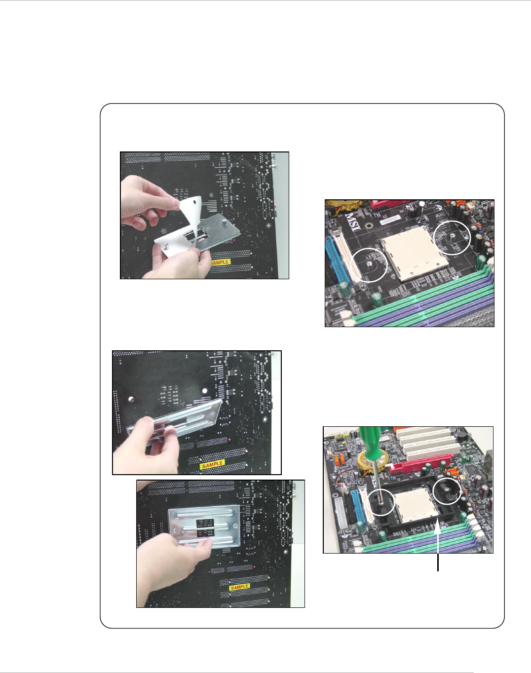
G-11
Benutzerhandbuch
Installation des AMD Athlon64 CPU Kühlersets
Wenn Sie die CPU einbauen, stellen Sie bitte sicher, dass Sie auf der
CPU einen Kühlkörper mit aktiven Prozessorlüfter anbringen, um
Überhitzung zu vermeiden. Verfügen Sie über keinen aktiven Prozessorlüfter mit
Kühlkörper, setzen Sie sich bitte mit Ihrem Händler in Verbindung, um einen solchen
zu erwerben und zu installieren, bevor Sie Ihren Computer anschalten.
1. Ziehen Sie die Schutzfolie von der
Klebstoffschicht der Rückplatte ab
2. Drehen Sie das Mainboard um und
bringen Sie die Rückplatte an der
geeigneten Stelle an.
3. Drehen Sie das Mainboard wieder auf
die Vorderseite und legen Sie es auf
einer ebenen Fläche ab.
Machen Sie die zwei Bohrungen auf
dem Mainboard ausfinding.
4. Richten Sie den Rückhalte-
mechanismus und die Rückplatte
aufeinander aus.
Sichern Sie beide mit zwei Schrauben
gegeneinander.
Rückhaltemechanismus
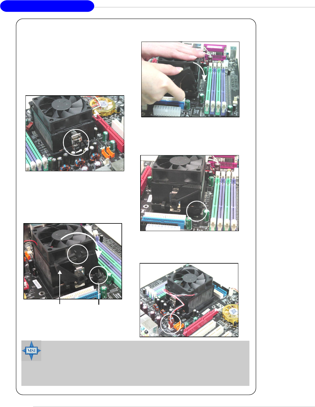
G-12
MS-7125 ATX Mainboard
7. Drücken Sie den Sicherungshebel
herab.
8. Stellen Sie sicher, dass der Sicher-
ungshaken den Sicherungsbolzen
des Rückhaltemechanismus
vollständig umschliesst.
9. Verbinden Sie das Stromkabel des
CPU Lüfters mit dem Anschluss auf
dem Mainboard.
MSI weist darauf hin...
Es besteht Verletzungsgefahr, wenn Sie den Sicherungs-haken vom
Sicherungsbolzen trennen. Sobald der Sicher-ungshaken gelöst
wird, schnellt der Sicherungshaken sofort zurück.
6. Machen Sie den Sicherungshebel,
den Sicherungshaken und den
Sicherungsbolzen ausfindig.
Heben Sie den Sicherungshebel
5. Setzen Sie das Kühlerset auf den
Rückhaltemechanismus.
Haken Sie zuerst ein Ende des
Haltebügels ein, dann drücken Sie
das andere Ende des Bügels
herunter, um das Kühlerset auf
dem Rückhaltemechanismus zu
befestigen.
Sicherungs-
haken
Sicherungsbolzen
Sicherungshebel
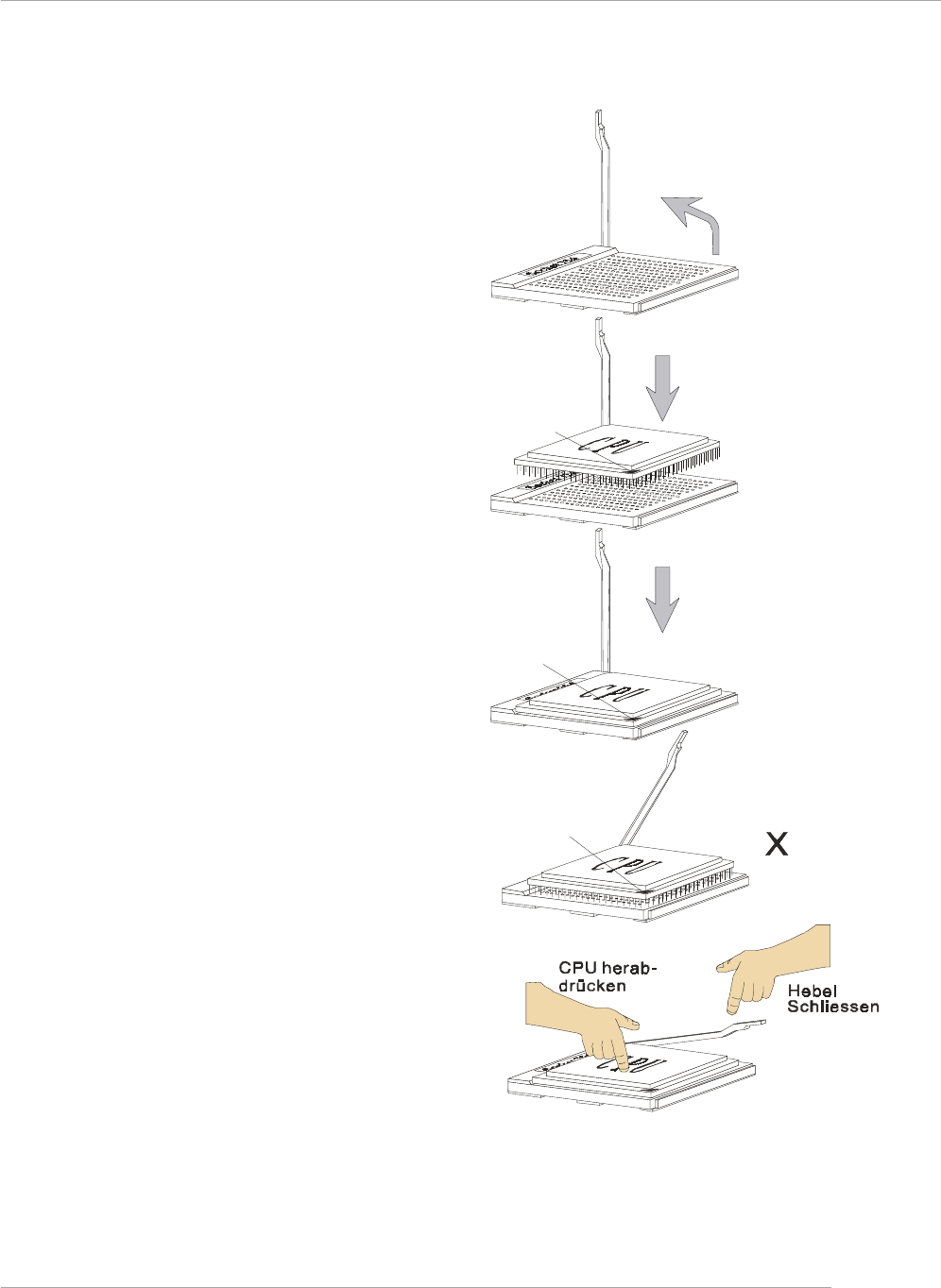
G-13
Benutzerhandbuch
CPU Einbau Sockel 939
Hebel
鐪
fnen
90 Grad
Gleitplatte
Goldener
Pfeil
Goldener
Pfeil
Goldener
Pfeil
Richtige Platzierung
der CPU
Falsche Platzierung
der CPU
O
1. Bitte Schalten Sie das System
aus und ziehen Sie den Netz-
stecker, bevor Sie die CPU
einbauen.
2. Ziehen Sie den Hebel leicht
seitlich weg vom Sockel, heben
Sie ihn danach bis zu einem
Winkel von ca. 90° an.
3. Suchen Sie nach einem goldenen
Pfeil. Der goldene Pfeil sollte auf
das Hebelgelenk zeigen. Die CPU
passt nur in der korrekten Aus-
richtung.
4. Ist die CPU korrekt installiert,
sollten die Pins an der Unterseite
vollständig versenkt und nicht
mehr sichtbar sein. Beachten Sie
bitte, dass jede Abweichunng
von der richtigen Vorgehens-
weise beim Einbau Ihr Mainboard
dauerhaft beschädigen kann.
5. Drücken Sie die CPU fest in den
Sockel und drücken Sie den
Hebel wieder nach unten bis in
seine Ursprungsstellung. Da die
CPU während des Schließens
des Hebels dazu neigt, sich zu
bewegen, sichern Sie diese bitte
während des Vorgangs durch
permanenten Fingerdruck von
oben, um sicherzustellen, dass
die CPU richtig und vollständig
im Sockel sitzt.
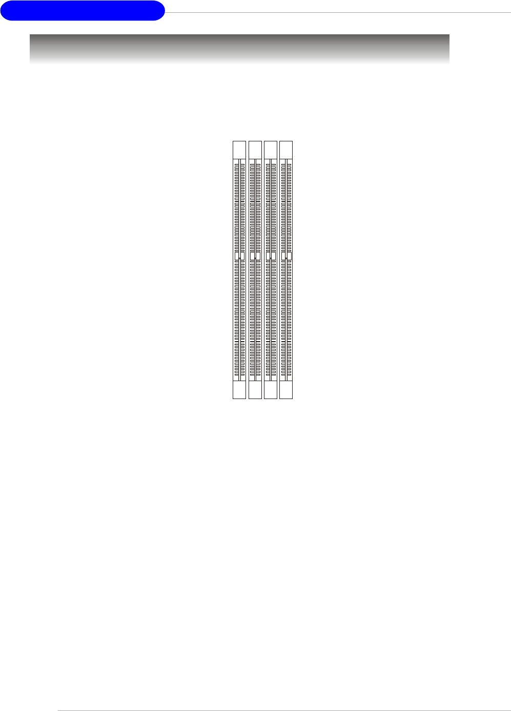
G-14
MS-7125 ATX Mainboard
Speicher
DIMM1~4
(von links nach
rechts)
Das Mainboard bietet Platz für vier 184-pin DDR SDRAM DIMMs (Double In-Line Memory
Module) und unterstützt den Speicherausbau auf bis zu 4GB. Sie können DDR266/
333 oder 400 Module in die DDR DIMM Sockel einsetzen (DDR 1- 4).
Um den letzten Stand bezüglich der unterstützten Speichermodule zu erhalten,
besuchen Sie bitte http://www.msi.com.tw/program/products/mainboard/mbd/
pro_mbd_trp_list.php
DDR Speicherzusammensetzung
Setzen Sie mindestens ein Speichermodul in einen Stecksockel. Jeder DIMM
Sockel unterstützt einen Speicherriegel mit maximal 1 GB. Gemäß Ihren Anforderungen
können Sie entweder ein- oder doppelseitige Module verwenden. Bitte beachten Sie,
dass jedes DIMM jeweils im Einkanal- DDR- Betrieb verwendet werden kann,
jedoch einige Regeln beachtet werden müssen, falls Sie sie im
Zweikanalbetrieb verwenden wollen. (Entnehmen Sie bitte der Tabelle unten die
Vorschläge zur Speicherbestückung). Sie können Speicherriegel unterschiedlichen
Typs und unterschiedlicher Größe in unterschiedlichen Speicherkanälen verwenden.
Es kann jedoch zu Stabilitätsproblemen kommen, falls Sie nicht Module gleichen
Typs und gleicher Größe im Zweikanalbetrieb verwenden. Bitte entnehmen Sie
der folgenden Tabelle detailliert geeignete Zweikanalanordnungen. Abweichende
Speicherzusammenstellungen, die unten nicht aufgeführt sind, funktionieren als
Einkanalspeicher.
Einführung zu DDR SDRAM
DDR (Double Data Rate) SDRAM entspricht konventionellem SDRAM, verdoppelt
aber die Datenrate, indem in jedem Taktzyklus zweimal Daten übertragen werden. Es
werden im Gegensatz zu den 3,3 Volt des SDR SDRAMS 2,5 Volt verwendet, und
ebenso statt einem 168- Pin Modul ein 184- Pin Modul. Die hohe Speicherbandbreite
macht DDR zur idealen Lösung für Hochleistungs- PCs, Workstations und Server.
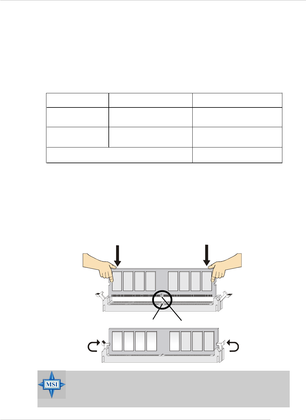
G-15
Benutzerhandbuch
DIMM Modulzusammensetzung
Setzen Sie mindestens ein Speichermodul in einen Stecksockel ein. Die Speichermodule
können in beliebiger Reihenfolge eingesetzt werden. Gemäß Ihren Anforderungen
können Sie entweder ein- oder doppelseitige Module verwenden.
Die Speichermodule können in jeder der folgenden Kombinationen eingesetzt werden:
Vorgehensweise beim Einbau von DDR Modulen
1. DDR DIMMs haben nur eine Kerbe in der Mitte des Moduls. Sie passen nur in
einer Richtung in den Sockel.
2. Setzen Sie den DIMM- Speicherbaustein senkrecht in den DIMM- Sockel, dann
drücken Sie ihn hinein, bis die goldenen Kontakte tief im Sockel sitzen.
3. Die Plastikklammern an den Seiten des DIMM- Sockels schließen sich
automatisch.
Volt Kerbe
MSI weist darauf hin...
Die goldenen Kontakte sind kaum noch sichtbar, wenn die Module
richtig eingesetzt sind.
E: Einseitig D: Doppelseitig
Sockel Speichermodule Gesamtspeicher
DDR 2
(Bank 2 & 3) E/D 64MB~1GB
Maximaler Systemspeicherausbau 64MB~2GB
DDR 1
(Bank 0 & 1) E/D 64MB~1GB

G-16
MS-7125 ATX Mainboard
BIOS Setup
Nach dem Einschalten beginnt der Computer den POST (Power On Self Test -
Selbstüberprüfung nach Anschalten). Sobald die Meldung unten erscheint, drücken
Sie die Taste <Entf>(<Del>) um das Setup aufzurufen.
Press DEL to enter SETUP
Wenn die Nachricht verschwindet, bevor Sie reagieren und Sie möchten immer
noch ins Setup, starten Sie das System neu, indem Sie es erst AUS- und danach
wieder ANSCHALTEN, oder die “RESET”-Taste am Gehäuse betätigen. Sie können
das System außerdem neu starten, indem Sie gleichzeitig die Tasten <Strg>,<Alt> und
<Entf> drücken (bei manchen Tastaturen <Ctrl>,<Alt> und <Del>).
Steuertasten
<↑> Vorhergehender Menüpunkt
<↓> Nächster Menüpunkt
<←> Ein Eintrag nach links
<→> Ein Eintrag nach rechts
<Eingaber> Auswahl eines Eintrages
<Esc> Menü verlassen oder Aufruf des Hauptmenüs aus
Untermenü
<+/Bild auf> Hochzählen eines Wertes oder Ändern
<-/Bild ab> Herunterzählen eines Wertes oder Änderns
<F5> Wiederherstellung der vorhergehenden Werte
<F7> Wählt Standardwerte für den leistungsmaximalen Betrieb
<F10> Speichern aller Änderungen im CMOS u.Verlassen d. BIOS

G-17
Benutzerhandbuch
The Main Menu
Standard CMOS Features
In diesem Menü können Sie die Basiskonfiguration Ihres Systems anpassen, so z.B.
die Uhrzeit, das Datum usw.
Advanced BIOS Features
Verwenden Sie diesen Menüpunkt, AWARD® spezifische weitergehende Einstellungen
an Ihrem System vorzunehmen.
Advanced Chipset Features
Verwenden Sie dieses Menü, um die Werte in den Chipsatzregistern zu ändern und
die Leistungsfähigkeit Ihres Systems zu optimieren.
Integrated Peripherals
Verwenden Sie dieses Menü, um die Einstellungen für integrierte Peripheriegeräte
vorzunehmen.
Power Management Setup
Verwenden Sie dieses Menü, um die Einstellungen für die Stromsparfunktionen
vorzunehmen.
PNP/PCI Configurations
Dieser Eintrag erscheint, wenn Ihr System Plug and Play- Geräte am PCI-Bus
unterstützt.
H/W Monitor
Hier können Sie Ihre Einstellungen für Hardware festlegen.
Nachdem Sie das Phoenix-Award® BIOS CMOS Setup Utility, aufgerufen haben,
erscheint das Hauptmenü. Es weist zwölf Setup- Funktionen und zwei Arten das
Menü zu verlassen auf. Verwenden Sie die Pfeiltasten, um im Menü zu navigieren
und drücken Sie die Eingabetaste (<Enter>), um ein Untermenü aufzurufen.

G-18
MS-7125 ATX Mainboard
Cell Menu
Hier können Sie die Einstellungen bezüglich Frequenz und Spannung von CPU und
AGP sowie zur Übertaktung vornehmen.
Load Optimized Defaults
Hier können Sie die Werkseinstellungen des BIOS für die höchste Systemleistung
laden, diese können jedoch zu Stabilitätsproblemen führen.
BIOS Setting Password
Verwenden sie dieses Menü, um das Kennwort für den BIOS- Zugriff einzugeben.
Save & Exit Setup
Abspeichern der BIOS-Änderungen im CMOS und verlassen des BIOS.
Exit Without Saving
Verlassen des BIOS´ ohne Speicherung, vorgenommene Änderungen verfallen
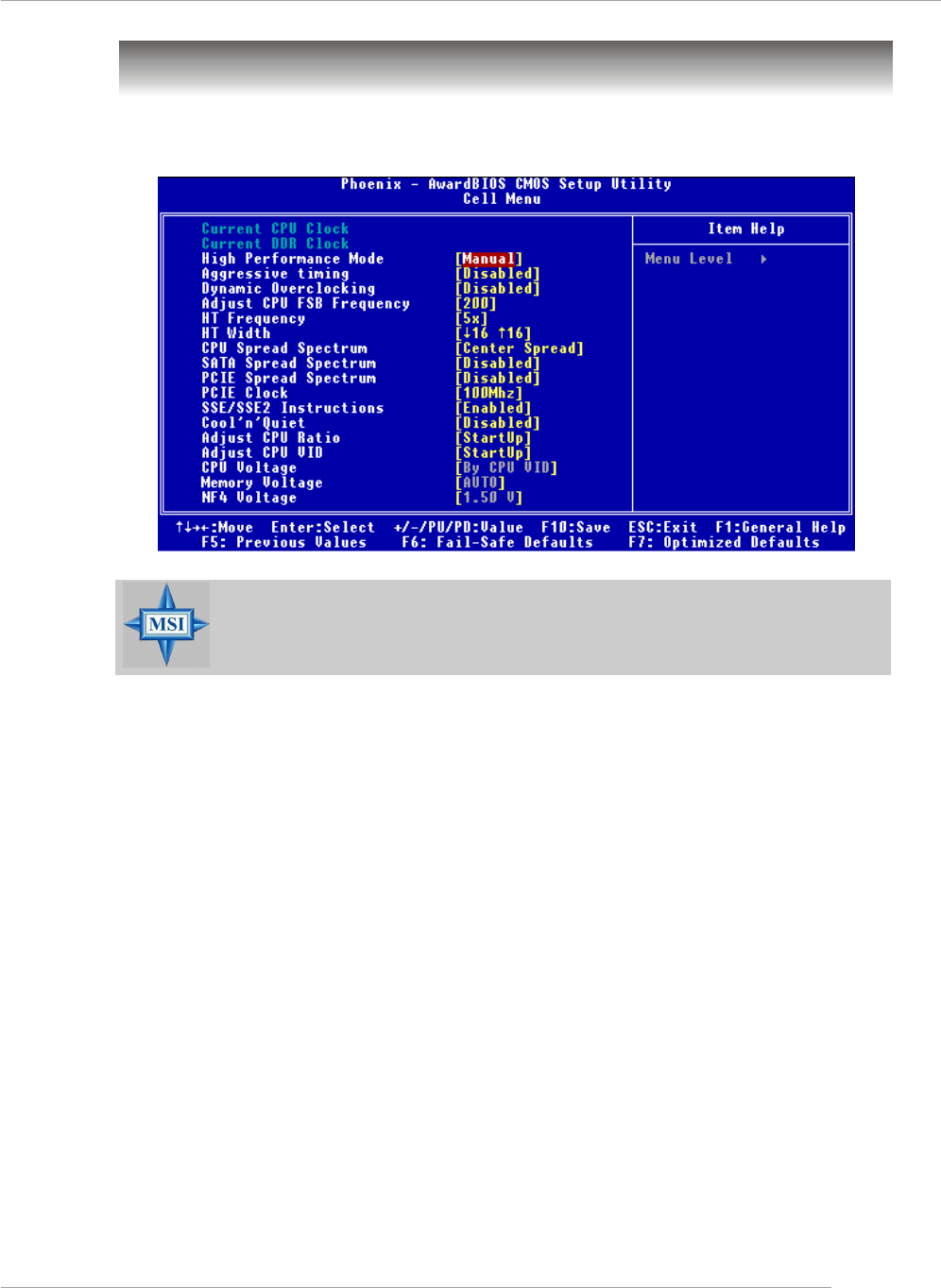
G-19
Benutzerhandbuch
Cell Menu
Hier können Sie wichtige Einstellungen bezüglich CPU, AGP und DRAM, sowie
zur Übertaktung vornehmen.
Current CPU / DDR Clock
Diese beiden Punkte zeigen die derzeitige Taktung der CPU und des eingebauten
Speichers an. Nur Anzeige.
MSI weist darauf hin...
Ändern Sie diese Einstellungen nur, wenn Sie mit diesem Chipsatz
vertraut sind.
High Performance Mode
Gestattet Ihnen die Einstellungen des DDR Timings. Mögliche Einstellungen: [Optimized],
[Manual].
Aggressive timing
Gestattet den Speichertakt ein- oder auszuschalten. Lautet die Auswahl [Enabled]
(eingeschaltet), wird die Verzögerung im Speichertiming verkürzt, um eine
Leistungssteigerung zu erzielen. [Enabled] (eingeschaltet) oder [Disabled]
(ausgeschaltet).

G-20
MS-7125 ATX Mainboard
Adjust CPU FSB Frequency
Gestattet es, die Taktfrequenz(in Mhz) des CPU Front Side Bus zu wählen. Wählen
Sie die benötigte Frequenz als Zahl zwischen [200] und [400].
HT Frequency
Setzt die maximale Betriebsfrequenz des Taktgebers des Hypertransport Links fest.
Mögliche Einstellungen: [1x], [1.5x], [2x], [2.5x], [3x], [4x], [5x].
HT Width
Dies dient zur Einstellung der HT Bandbreite zwischen CPU & Chip.Die Markierung
“↑“ bedeuted Bandbreite vom Chip zur CPU. Ein ↓ bedeutet HT Bandbreite vom CPU
zum Chip HT. Mögliche Einstellungen: [ ↓ 8 ↑ 8], [ ↓ 16 ↑ 8], [↓ 8 ↑16], [ ↓16 ↑16].
CPU Spread Spectrum
Dient zum Ein- oder Ausschalten der CPU Spread Spectrum Funktion. Setzen Sie
diese Einstellung stets [Disabled] (ausgeschaltet), wenn Sie die CPU übertakten.
Mögliche Einstellungen: [Center Spread], [Disabled] (ausgeschaltet).
Dynamic Overclocking
Dynamic Overclocking Technology (D.O.T) ist die automatische Übertaktungsfunktion,
die in MSITM’s neu entwickelter CoreCellTM Technologie enthalten ist. Sie dient zur
Feststellung des Auslastungsgrades der CPU, während diese Programme abarbeitet,
und passt die CPU-Frequenz automatisch an. Stellt das Motherboard fest, dass die
CPU Programme ausführt, beschleunigt es automatisch die CPU und erlaubt so eine
flüssige und schnellere Ausführung. Ist die CPU ohne Last oder nur wenig ausgelastet,
werden statt dessen die Voreinstellungen wieder hergestellt. Üblicherweise kommt
die Technologie der dynamischen Übertaktung nur zum Einsatz, wenn große
Datenmengen bewältigt werden müssen, wie das bei 3D Spielen oder der
Videoverarbeitung der Fall ist. In diesen Fällen ist es notwendig, die CPU -Frequenz
zu erhöhen, um die Gesamtleistung des Systems zu erhöhen. Die möglichen
Einstellungen sind:
[Disabled] Dynamic Overclocking ist ausgeschaltet.
[Private] Erste Übertaktungsstufe, Steigerung der CPU Frequenz um 1%.
[Sergeant] Zweite Übertaktungsstufe, Steigerung der CPU Frequenz um 3%.
[Captain] Dritte Übertaktungsstufe, Steigerung der CPU Frequenz um 5%,
ebenso die Voreinstellung für "Load High Performance Defaults".
[Colonel] Vierte Übertaktungsstufe, Steigerung der CPU Frequenz um 7%.
[General] Fünfte Übertaktungsstufe, Steigerung der CPU Frequenz um 9%.
[Commander] Sechste Übertaktungsstufe, Steigerung der CPU Frequenz um
11%.
MSI weist darauf hin...
Obgleich Dynamic Overclocking Technology stabiler ist, als
manuelles Übertakten, ist es dennoch grundsätzlich riskant. Es ist
empfehlenswert zuerst sicher zu stellen, dass Ihre CPU eine
regelmäßige Übertaktung verträgt. Sollten Sie feststellen, dass Ihr
PC instabil erscheint oder ohne erkennbaren Grund Neustarts
durchführt, it es besser, die dynamische Übertaktung abzuschalten
oder aber eine niedrigere Übertaktungsstufe zu wählen. Im Übrigen
ist zu erwähnen, dass Sie den D.O.T Ranger zuerst abschalten
müssen, bevor Sie Ihr System manuell übertakten.

G-21
Benutzerhandbuch
SATA Spread Spectrum
Dient zum Ein- oder Ausschalten der SATA Spread Spectrum Funktion. Mögliche
Einstellungen: [Disabled] (ausgeschaltet), [Down Spread].
PCIE Spread Spectrum
Dient zum Ein- oder Ausschalten der PCIE Spread Spectrum Funktion. Setzen Sie
diese Einstellung stets [Disabled] (ausgeschaltet), wenn Sie die CPU übertakten.
Mögliche Einstellungen: [Disabled] (ausgeschaltet), [Down Spread].
PCIE Clock
Gestattet es, die Taktfrequenz (in Mhz) des PCIE Bus zu wählen. Wählen Sie die
benötigte Frequenz als Zahl zwischen [100] und [145].
K8 CPU SSE/ SSE2 Instructions
Diese Einstellung schaltet die SSE/SSE2 Instructions ein-/aus. Die Streaming SIMD
Extensions (SSE) wurden mit dem Pentium III Prozessor eingeführt. Die SSE
Erweiterungen bestehen aus einem neuen Satz von Befehlen und einem neuen Satz
von Registern. Diese Befehle und Register wurden entworfen, um Single-Instruction
Multiple-Data (SIMD) Berechnungen mit einfach präzisen Fließkommazahlen
durchzuführen.
Die Streaming SIMD Extensions2 (SSE2) wurden mit den Pentium 4 und Intel Xeon
Prozessoren eingeführt. Sie bestehen aus einem neuen Satz von Befehlen die in den
XXM und MXCSR Registern arbeiten und SIMD Operationen mit zweifach präzisen
Fließkommazahlen und Ganzzahlwerten durchführen. Verschiedene dieser neuer
SSE/SSE2 Anweisungen arbeiten auch in den MMX Registern. Mögliche Einstellungen:
[Enabled] (eingeschaltet) oder [Disabled] (ausgeschaltet).
Cool’n’Quiet control
Wurde speziell für AMD Athlon Prozessoren entworfen, und stellt eine Funktion zur
Erfassung der CPU Temperatur bereit, um Ihre CPU vor Überhitzung durch hohe Last
zu bewahren. Mögliche Einstellungen: [Disabled] (ausgeschaltet), [Auto].
MSI weist darauf hin...
Um einen stabilen Betrien der Cool'n'Quiet Funktion sicher zu stellen,
ist es immer angeraten, die Speicherbank DMM1 zu bestücken.

G-22
MS-7125 ATX Mainboard
Adjust CPU Ratio
Hier können Sie den CPU-Taktrelation (Taktmultiplikator) angeben. Die Einstellung
[Startup] ermöglicht es dem Prozessor mit der schnellsten vom System ermittelten
Geschwindigkeit zu laufen. Die möglichen Einstellungen sind:[Startup], [x4] bis [x12].
Adjust CPU VID
Erlaubt Ihnen die CPU VID anzupassen. Die Einstellung [Startup] gestattet es der CPU
mit der voreingestellten VID zu laufen, welche vom System erkannt wird. Mögliche
EInstellungen: [Startup], [0.825V], [0.850V],[0.875V],~, [1.550V].
CPU Voltage
Gestattet die Anpassung der CPU Spannung. Mögliche EInstellungen: [By CPU VID],
[Over VID 3.3%], [Over VID 5.0%],[Over VID 8.3%].
Memory Voltage
Die Spannung des DDR anzuheben, kann diesen beschleunigen. Jede Änderung dieser
Option kann zu Stabilitätsproblemen führen, deswegen wird von einer langfristigen
Änderung der DDR Spannung ABGERATEN. Mögliche EInstellungen:[Auto], [2.
50V]~[2.85V].
NF4 Voltage
Gestattet die Anpassung der NF4 Spannung. Mögliche EInstellungen: [1.50V]~[1.
85V].
MSI weist darauf hin...
Die unterschiedliche Farbgebung der Punkte CPU Voltage, Memory
Voltage und NF4 Voltage hilft Ihnen zu überprüfen, ob Ihre
Einstellungen für Ihr System angemessen sind.
Grau: Voreinstellung.
Gelb: Hochleistungseinstellung.
Rot: Nicht empfehlenswerte Einstellung, das System kann
instabil sein.
CPU Voltage, Memory Voltage und NF4 Voltage zu verändern
kann zur Instabilität des Systems führen, aus diesem Grunde wird
davon ABGERATEN, längerfristig von den Voreinstellungen
abzuweichen.
