Msi Ms 96C8 Series Owner S Manual 96C8v1.0 Preface.p65
2014-07-06
: Msi Msi-Ms-96C8-Series-Owner-S-Manual msi-ms-96c8-series-owner-s-manual msi pdf
Open the PDF directly: View PDF ![]() .
.
Page Count: 113 [warning: Documents this large are best viewed by clicking the View PDF Link!]

ii
Copyright Notice
The material in this document is the intellectual property of MICRO-STAR
INTERNATIONAL. We take every care in the preparation of this document, but no
guarantee is given as to the correctness of its contents. Our products are under
continual improvement and we reserve the right to make changes without notice.
Trademarks
All trademarks are the properties of their respective owners.
NVIDIA, the NVIDIA logo, DualNet, and nForce are registered trademarks or trade-
marks of NVIDIA Corporation in the United States and/or other countries.
AMD, Athlon™, Athlon™ XP, Thoroughbred™, and Duron™ are registered trade-
marks of AMD Corporation.
Intel® and Pentium® are registered trademarks of Intel Corporation.
PS/2 and OS®/2 are registered trademarks of International Business Machines
Corporation.
Windows® 98/2000/NT/XP/Vista are registered trademarks of Microsoft Corporation.
Netware® is a registered trademark of Novell, Inc.
Award® is a registered trademark of Phoenix Technologies Ltd.
AMI® is a registered trademark of American Megatrends Inc.
Revision History
Revision Revision History Date
V1.0 First release April 2009
Technical Support
If a problem arises with your system and no solution can be obtained from the user’s
manual, please contact your place of purchase or local distributor. Alternatively,
please try the following help resources for further guidance.
Visit the MSI website for FAQ, technical guide, BIOS updates, driver up-
dates and other information: http://www.msi.com/index.php?func=service
Contact our technical staff at: http://ocss.msi.com
PDF created with pdfFactory Pro trial version www.pdffactory.com

iii
Safety Instructions
1. Always read the safety instructions carefully.
2. Keep this User’s Manual for future reference.
3. Keep this equipment away from humidity.
4. Lay this equipment on a reliable flat surface before setting it up.
5. The openings on the enclosure are for air convection hence protects the equip-
ment from overheating. DO NOT COVER THE OPENINGS.
6. Make sure the voltage of the power source and adjust properly 110/220V be-
fore connecting the equipment to the power inlet.
7. Place the power cord such a way that people can not step on it. Do not place
anything over the power cord.
8. Always Unplug the Power Cord before inserting any add-on card or module.
9. All cautions and warnings on the equipment should be noted.
10. Never pour any liquid into the opening that could damage or cause electrical
shock.
11. If any of the following situations arises, get the equipment checked by service
personnel:
The power cord or plug is damaged.
Liquid has penetrated into the equipment.
The equipment has been exposed to moisture.
The equipment does not work well or you can not get it work according to
User’s Manual.
The equipment has dropped and damaged.
The equipment has obvious sign of breakage.
12. DO NOT LEAVE THIS EQUIPMENT IN AN ENVIRONMENT UNCONDITIONED, STOR-
AGE TEMPERATURE ABOVE 600 C (1400F), IT MAY DAMAGE THE EQUIPMENT.
CAUTION: Danger of explosion if battery is incorrectly replaced.
Replace only with the same or equivalent type recommended by the
manufacturer.
此为
A
级产品,在生活环境中,该产品可能会造成无线电干扰。
在这种情况下,可能需要用户对其干扰采取切实可行的措施。
PDF created with pdfFactory Pro trial version www.pdffactory.com

iv
FCC-B Radio Frequency Interference Statement
This equipment has been
tested and found to comply
with the limits for a Class B
digital device, pursuant to Part
15 of the FCC Rules. These limits are designed to provide reasonable protection
against harmful interference in a residential installation. This equipment generates,
uses and can radiate radio frequency energy and, if not installed and used in accor-
dance with the instructions, may cause harmful interference to radio communications.
However, there is no guarantee that interference will not occur in a particular
installation. If this equipment does cause harmful interference to radio or television
reception, which can be determined by turning the equipment off and on, the user is
encouraged to try to correct the interference by one or more of the measures listed
below.
† Reorient or relocate the receiving antenna.
† Increase the separation between the equipment and receiver.
† Connect the equipment into an outlet on a circuit different from that to
which the receiver is connected.
† Consult the dealer or an experienced radio/television technician for help.
Notice 1
The changes or modifications not expressly approved by the party responsible for
compliance could void the user’s authority to operate the equipment.
Notice 2
Shielded interface cables and A.C. power cord, if any, must be used in order to
comply with the emission limits.
VOIR LA NOTICE D ’INSTALLATION AVANT DE RACCORDER AU RESEAU.
Micro-Star International
MS-96C8
This device complies with Part 15 of the FCC Rules. Operation is subject to the
following two conditions:
(1) this device may not cause harmful interference, and
(2) this device must accept any interference received, including interference that
may cause undesired operation.
PDF created with pdfFactory Pro trial version www.pdffactory.com


viii
CONTENTS
Copyright Notice..............................................................................................................ii
Trademarks.......................................................................................................................ii
Revision History..............................................................................................................ii
Technical Support...........................................................................................................ii
Safety Instructions.........................................................................................................iii
FCC-B Radio Frequency Interference Statement........................................................iv
WEEE (Waste Electrical and Electronic Equipment) Statement....................................v
Chapter 1 Getting Started.....................................................................................1-1
Mainboard Specifications...................................................................................1-2
Mainboard Layout................................................................................................1-4
Chapter 2 Hardware Setup....................................................................................2-1
Quick Components Guide....................................................................................2-2
CPU (Central Processing Unit)............................................................................2-3
Memory.................................................................................................................2-7
Power Supply......................................................................................................2-8
Back Panel I/O......................................................................................................2-9
Connector..........................................................................................................2-10
Jumper................................................................................................................2-17
Slot......................................................................................................................2-18
Chapter 3 BIOS Setup.............................................................................................3-1
Entering Setup.....................................................................................................3-2
The Menu Bar......................................................................................................3-4
Main......................................................................................................................3-5
Advanced............................................................................................................3-6
Boot....................................................................................................................3-20
Security..............................................................................................................3-24
Chipset...............................................................................................................3-25
Exit......................................................................................................................3-29
Appendix A Intel ICH10R SATA RAID...................................................................A-1
Introduction..........................................................................................................A-2
BIOS Configuration..............................................................................................A-3
Installing Driver..................................................................................................A-10
Installing Software............................................................................................A-12
RAID Migration Instructions...............................................................................A-16
Recovery Volume Creation...............................................................................A-23
Degraded RAID Array........................................................................................A-27
PDF created with pdfFactory Pro trial version www.pdffactory.com
ix
Appendix B LSI SAS RAID......................................................................................B-1
1. Introduction to Integrated RAID......................................................................B-2
2. Integrated Mirroring Overview.......................................................................B-3
3. Creating Integrated Mirroring Volumes..........................................................B-9
4. Integrated Striping Overview.......................................................................B-16
5. Creating Integrated Striping Volumes..........................................................B-19
PDF created with pdfFactory Pro trial version www.pdffactory.com

1-1
Getting Started
Getting Started
Chapter 1
Thank you for choosing the 5500 Master Series (MS-
96C8 V1.X), an excellent server board from MSI.
Based on the innovative Intel® 5500 & ICH10R chipsets
for optimal system efficiency, the 5500 Master Series
accommodate the latest 45nm Intel® Nehalem proces-
sor (up to 95W) in LGA1366 package and support up
to 6 DDR3 800/1066/1333 DIMM slots to provide the
maximum of 48GB memory capacity.
In the advanced-level and mid-range market segment,
the 5500 Master Series can provide a high-perform-
ance solution for today’s front-end and general pur-
pose server, as well as in the future.
PDF created with pdfFactory Pro trial version www.pdffactory.com

MS-96C8 Server Board
1-2
Mainboard Specifications
Processor
- 45nm Intel Nehalem processor (up to 95W) in LGA1366 package
Supported QPI
- Up to 6.4 GT/s
Chipset
- North Bridge: Intel 5500 chipset
- South Bridge: Intel ICH10R chipset
Memory
- 6 DDR3 800/1066/1333 DIMM slots
- Supports the maximum of 48GB RDIMM or 24GB UDIMM
LAN
- Supports Gb LAN by Intel 82574 & 82567 Gb Ethernet controller
IDE
- 1 IDE port by ITE IT8213F
- Supports Ultra DMA 66/100/133 mode
- Supports PIO, Bus Master operation mode
SATA
- 6 SATAII ports by Intel ICH10R
- Supports 6 SATAII devices
- Supports up to 3Gb/s data transfer rate
SAS
- 2 mini SAS ports by LSI Logic SAS1068E Host Controller
- Data transfer rate at up to 3Gb/s
Graphics
- Aspeed AST1100 (default)/ AST2050 (optional) graphics controller
Server Management
- Aspeed AST1100 (default)/ AST2050 (optional) BMC controller
with IPMI 2.0/1.5 compliance
PDF created with pdfFactory Pro trial version www.pdffactory.com
1-3
Getting Started
Onboard I/O
Back Panel
- 1 PS/2 mouse port
- 1 PS/2 keyboard port
- 2 USB 2.0 ports
- 1 serial port
- 1 D-Sub VGA port
- 2 RJ-45 LAN jacks
Onboard Connectors
- 2 USB 2.0 pinheaders (4 ports)
- 1 serial port connector
- 1 SMBus connector
- 1 SPI Flash ROM pinheader (for debugging)
- 1 chassis intrusion connector
- 1 TPM connector
Slot
- 1 PCI Express 2.0 x16 slot
- 1 PCI-Express 2.0 x8 slot
- 2 PCI-Express 2.0 x4 slots
- 1 32-bit/33MHz PCI slot
Dimension
- 12" x 10.5" SSI CEB form factor
Mounting
- 9 mounting holes
PDF created with pdfFactory Pro trial version www.pdffactory.com
MS-96C8 Server Board
1-4
B
A
T
T
+
USB Ports
T: Mouse
B: Keyboard
COM1
VGA1
JLAN1
JLAN2
CLR_CMOS
JPWR1
JPWR3
iTE
IT8213F
SYS_FAN5
CPU1_FAN
JPWR2
S
A
T
A
4
S
A
T
A
2
S
A
T
A
0
S
A
T
A
5
S
A
T
A
3
S
A
T
A
1
MINISAS1
M
I
N
I
S
A
S
2
JCD1
JID1
JTPM1
COM2
JSMBUS1
JSSI1
JUSB2 JUSB3
SYS_FAN1
SYS_FAN2
SYS_FAN4
CPU0_FAN
SYS_FAN3
J2
PCI_E1
CPU1
CPU0
CPU1_DIMM3CPU1_DIMM3
CPU0_DIMM1
CPU1_DIMM2CPU1_DIMM2
CPU0_DIMM2
CPU1_DIMM1CPU1_DIMM1
CPU0_DIMM3
PCI_E3
PCI_E4
PCI1
PCIE2
INTRUDER
RECOVERY
Intel
ICH10R
Intel
5500
LSI
SAS1068E
JBIOS_WP
JGPIO33
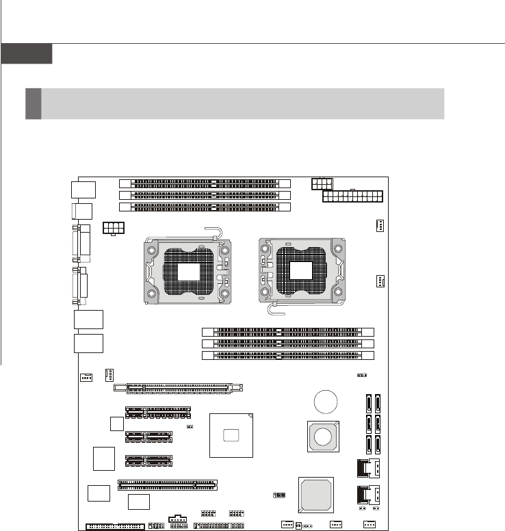
5500 Master Series (MS-96C8 V1.X) Server Board
Mainboard Layout
PDF created with pdfFactory Pro trial version www.pdffactory.com

2-1
Hardware Setup
Hardware Setup
Chapter 2
This chapter provides you with the information about
hardware setup procedures. While doing the installation,
be careful in holding the components and follow the
installation procedures. For some components, if you
install in the wrong orientation, the components will not
work properly.
Use a grounded wrist strap before handling computer
components. Static electricity may damage the
components.
PDF created with pdfFactory Pro trial version www.pdffactory.com
2-2
MS-96C8 Server Board
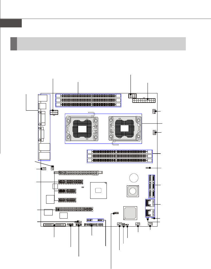
Quick Components Guide
B
A
T
T
+
JPWR2, p.2-8
CPU0_FAN,
p.2-12
JPWR3, p.2-8
DIMM Slots,
p.2-7
CPU, p.2-3
SYS_FAN4,
p.2-12
SYS_FAN5,
p.2-12
DIMM Slots, p.2-7
JPWR1, p.2-8
JSMBUS1,
p.2-14
JSSI1,
p.2-16
JUSB2~3,
p.2-13
COM2, p.2-12
SATA0~5,
p.2-11
INTRUDER, p.2-13
CLR_CMOS,
p.2-17
Back Panel
I/O, p.2-9
PCI Express
Slots, p.2-18
CPU1_FAN,
p.2-12
MINISAS1~2,
p.2-11
JCD1, p.2-10
JTPM1, p.2-15
SYS_FAN1, p.2-12
RECOVERY, p.2-17
SYS_FAN2, p.2-12
SYS_FAN3, p.2-12
J2, p.2-14
PCI Slot, p.2-18
JBIOS_WP,
p.2-17
JGPIO33,
p.2-14
PDF created with pdfFactory Pro trial version www.pdffactory.com
2-3
Hardware Setup
Important
Overheating
Overheating will seriously damage the CPU and system. Always make sure
the cooling fan can work properly to protect the CPU from overheating. Make
sure that you apply an even layer of thermal paste (or thermal tape) between
the CPU and the heatsink to enhance heat dissipation.
Replaceing the CPU
While replacing the CPU, always turn off the power supply or unplug the
power supply’s power cord from the grounded outlet first to ensure the safety
of CPU.
CPU (Central Processing Unit)
When you are installing the CPU, make sure that you install the cooler to
prevent the CPU from overheating. If you do not have the CPU cooler, consult
your dealer before turning on the computer.
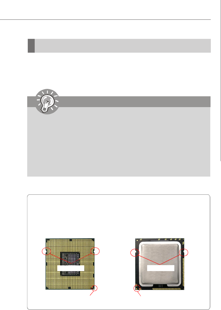
Introduction to LGA 1366 CPU
The surface of LGA 1366 CPU.
Remember to apply some ther-
mal paste on it for better heat
dispersion.
Yellow triangle is the Pin 1 indicator
The pin-pad side of LGA 1366
CPU.
Yellow triangle is the Pin 1 indicator
Alignment Key Alignment Key
PDF created with pdfFactory Pro trial version www.pdffactory.com
2-4
MS-96C8 Server Board
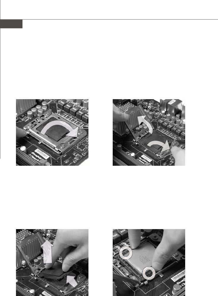
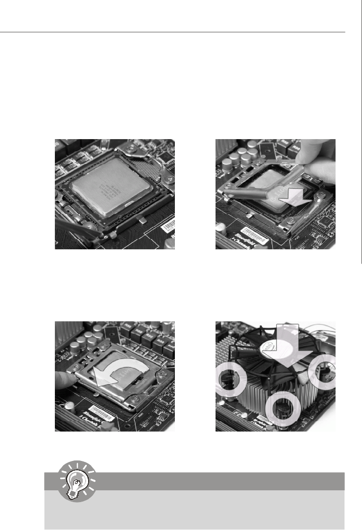
2.Lift the load lever up and open the
load plate.
1. Open the load level.
CPU & Cooler Installation
When you are installing the CPU, make sure the CPU has a cooler attached on
the top to prevent overheating. Meanwhile, do not forget to apply some thermal
paste on CPU before installing the heat sink/cooler fan for better heat dispersion.
Follow the steps below to install the CPU & cooler correctly. Wrong installation will
cause the damage of your CPU & mainboard.
4.After confirming the CPU direction for
correct mating, put down the CPU in
the socket housing frame. Be sure
to grasp on the edge of the CPU base.
Note that the alignment keys are
matched.
alignment key
3. The CPU socket has a plastic cap on
it to protect the contack from damage.
Before you install CPU, always cover
it to protect the socket pin. Romove
the cap from the lever hinge side (as
the arrow shows).
PDF created with pdfFactory Pro trial version www.pdffactory.com
2-5
Hardware Setup
6.Cover the load plate onto the
package.
5.Visually inspect if the CPU is seated
well into the socket. If not, take out
the CPU with pure vertical motion and
reinstall.
7.Press down the load lever lightly onto
the load plate, and then secure the
lever with the hook under retention
tab.
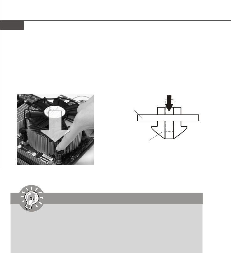
8.Align the holes on the mainboard with
the heatsink. Push down the cooler
until its four clips get wedged into
the holes of the mainboard.
Important
1.Confirm if your CPU cooler is firmly installed before turning on your system.
2. Do not touch the CPU socket pins to avoid damaging.
PDF created with pdfFactory Pro trial version www.pdffactory.com
2-6
MS-96C8 Server Board
9.Align the holes on the mainboard with
the heatsink. Push down the cooler
until its four clips get wedged into
the holes of the mainboard.
10. Turn over the mainboard to confirm
that the clip-ends are correctly
inserted.
Mainboard
Hook
Important
1. Read the CPU status in BIOS.
2. Whenever CPU is not installed, always protect your CPU socket pin with the
plastic cap covered (shown in Figure 1) to avoid damaging.
3. Mainboard photos shown in this section are for demonstration of the CPU/
cooler installation only. The appearance of your mainboard may vary depend-
ing on the model you purchase.
PDF created with pdfFactory Pro trial version www.pdffactory.com
2-7
Hardware Setup
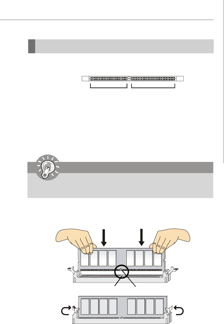
Memory
These DIMM slots are intended for system memory modules.
Installing Memory Modules
1. Locate the DIMM slots on the mainboard. Flip open the retaining clip at each side
of the DIMM slot.
2. Align the notch on the DIMM with the key on the slot. Insert the DIMM vertically into
the DIMM slot. Then push it in until the golden finger on the DIMM is deeply inserted
in the DIMM slot. The retaining clip at each side of the DIMM slot will automatically
close if the DIMM is properly seated.
3. Manually check if the DIMM has been locked in place by the retaining clips at the
sides.
4. Follow the same procedures to install more DIMMs if necessary.
Important
You can barely see the golden finger if the DIMM is properly inserted in the
DIMM slot.
Volt Notch
72x2=144 pin
DDR3
240-pin, 1.5V
48x2=96 pin
PDF created with pdfFactory Pro trial version www.pdffactory.com
2-8
MS-96C8 Server Board
Power Supply
PIN SIGNAL
13 +3.3V
14 -12V
15 GND
16 PS-ON#
17 GND
18 GND
19 GND
20 NC
21 +5V
22 +5V
23 +5V
24 GND
PIN SIGNAL
1 +3.3V
2 +3.3V
3 GND
4 +5V
5 GND
6 +5V
7 GND
8 PWR OK
9 +5VSB
10 +12V
11 +12V
12 +3.3V
JPWR2 Pin Definition
Important
1. Make sure that all power connectors are connected to the power supply to
ensure stable operation of the mainboard.
2. Power supply of 600 watts (and above) is highly recommended for system
stability.
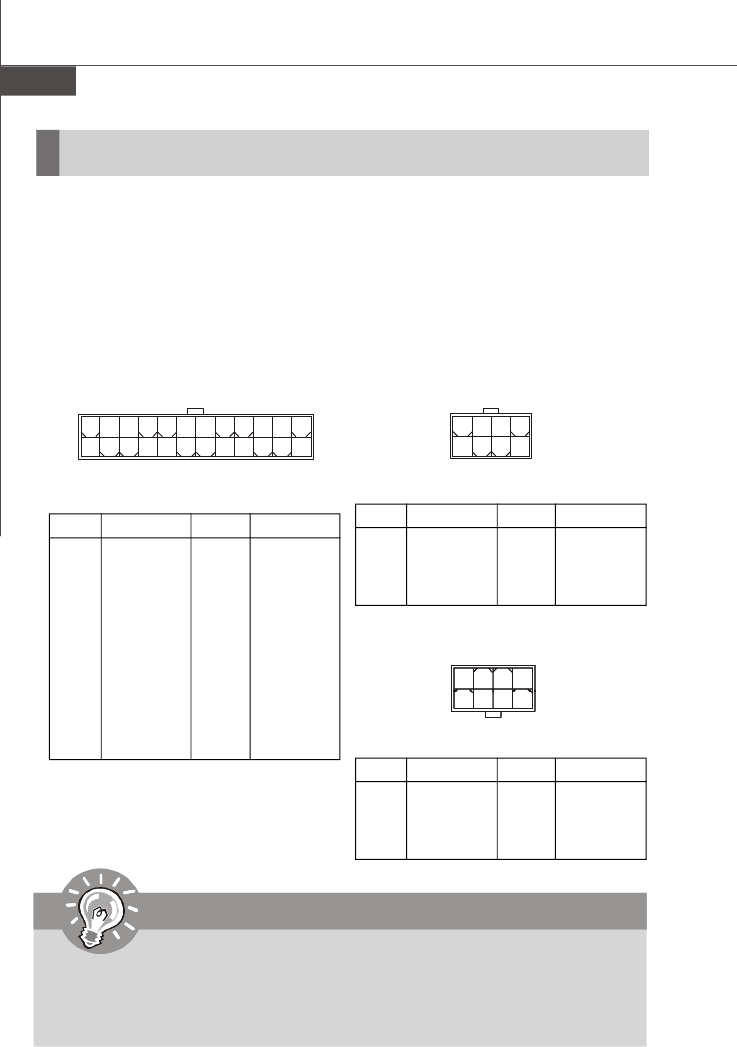
System Power Connector: JPWR2
This connector allows you to connect a power supply. To connect the power supply,
make sure the plug of the power supply is inserted in the proper orientation and the
pins are aligned. Then push down the power supply firmly into the connector.
CPU/Memory Power Connector: JPWR1, JPWR3
These connectors provide 12V power output to the CPUs & memory.
PIN SIGNAL
5+12V
6+12V
7+12V
8+12V
PIN SIGNAL
1GND
2GND
3GND
4GND
JPWR1 Pin Definition
JPWR2
12 1
24 13
JPWR1
1
8 5
4
PIN SIGNAL
5+12V
6+12V
7+12V
8+12V
PIN SIGNAL
1GND
2GND
3GND
4GND
JPWR3 Pin Definition
JPWR3
1
85
4
PDF created with pdfFactory Pro trial version www.pdffactory.com
2-9
Hardware Setup
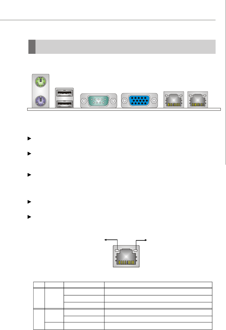
Back Panel I/O
LED Color LED State Condition
Off LAN link is not established.
Left Orange On (steady state) LAN link is established.
On (brighter & pulsing)The computer is communicating with another computer on the LAN.
Green Off 10 Mbit/sec data rate is selected.
Right On 100 Mbit/sec data rate is selected.
Orange On 1000 Mbit/sec data rate is selected.
Mouse/Keyboard
The standard PS/2® mouse/keyboard DIN connector is for a PS/2® mouse/keyboard.
USB Port
The USB (Universal Serial Bus) port is for USB devices such as keyboard, mouse, or
other USB-compatible devices.
Serial Port
The serial port is a 16550A high speed communications port that sends/ receives 16
bytes FIFOs. You can attach a serial mouse or other serial devices directly to the
connector.
VGA Port
The DE-15 female connector is provided for monitor.
LAN
The standard RJ-45 LAN jack is for connection to Local Area Network (LAN). You
can connect a network cable to it.
Link/Active Indicator Mode Indicator
RJ-45 LAN Jack
Keyboard
Mouse
LAN Jacks
Serial PortUSB Ports VGA Port
PDF created with pdfFactory Pro trial version www.pdffactory.com
2-10
MS-96C8 Server Board
Connector
Important
If you install two IDE devices on the same cable, you must configure the
drives separately to master / slave mode by setting jumpers. Refer to IDE
device’s documentation supplied by the vendors for jumper setting
instructions.
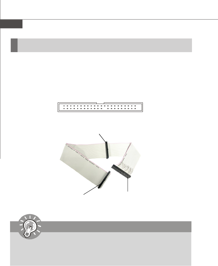
JCD1
44-Pin IDE Connector: JCD1
This 44-pin IDE connector connects to an optional converter that enables connection
to one 44-pin IDE device and one 40-pin IDE device, such as hard disk drives, CD-
ROM and other IDE devices.
Connect to JCD1 Connect to 40-pin
IDE device
Connect to 44-pin
IDE device
PDF created with pdfFactory Pro trial version www.pdffactory.com
2-11
Hardware Setup
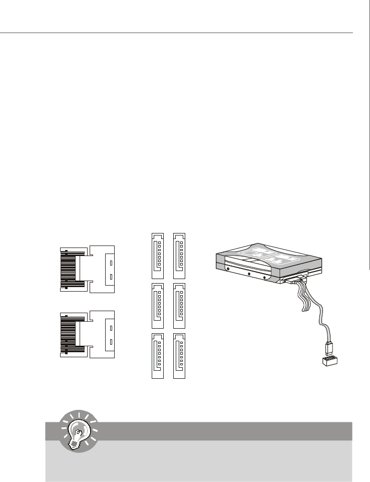
Serial Attached SCSI Connector: MINISAS1, MINISAS2
The SAS connector is a new generation serial communication protocol for devices
designed to allow for much higher speed data transfers. It supports data transfer
speeds up to 3 Gbit/s. SAS uses serial communication instead of the parallel method
found in traditional SCSI devices but still uses SCSI commands for interacting with
SAS devices. Each SAS connector can connect to 1 disk drive.
Serial ATA Connector: SATA0 ~ SATA5
This connector is a high-speed Serial ATA interface port. Each connector can con-
nect to one Serial ATA device.
MINISAS2
MINISAS1
SATA5
SATA4
SATA3
SATA2
SATA1
SATA0
Important
Please do not fold the SATA/SAS accessory cable into 90-degree angle.
Otherwise, data loss may occur during transmission.
PDF created with pdfFactory Pro trial version www.pdffactory.com
2-12
MS-96C8 Server Board
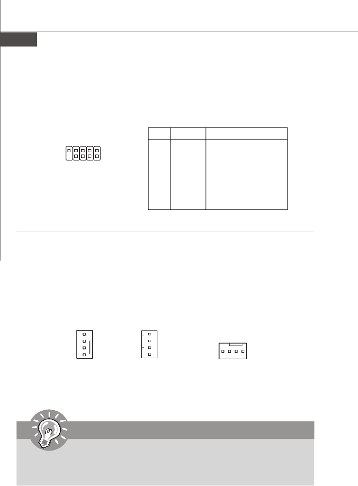
Fan Power Connector: CPU0_FAN, CPU1_FAN, SYS_FAN1/2/3/4/5
The fan power connectors support system cooling fan with +12V. When connecting
the wire to the connectors, always note that the red wire is the positive and should
be connected to the +12V; the black wire is Ground and should be connected to GND.
If the mainboard has a System Hardware Monitor chipset onboard, you must use a
specially designed fan with speed sensor to take advantage of the CPU fan control.
Important
Please refer to the recommended CPU fans at processor’s official website or
consult the vendors for proper CPU cooling fan.
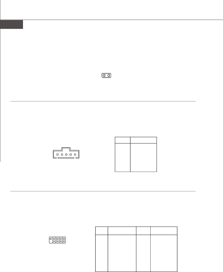
Serial Port Connector: COM2
This connector is a 16550A high speed communications port that sends/receives 16
bytes FIFOs. You can attach a serial device to it through the optional serial port
bracket.
PIN SIGNAL DESCRIPTION
1 DCD Data Carry Detect
2 SIN Serial In or Receive Data
3 SOUT Serial Out or Transmit Data
4 DTR Data Terminal Ready
5 GND Ground
6 DSR Data Set Ready
7 RTS Request To Send
8 CTS Clear To Send
9 RI Ring Indicate
Pin Definition
CPU0_FAN
SENSOR
+12V
GND
CONTROL
CPU1_FAN,
SYS_FAN4
SENSOR
+12V
GND
CONTROL
SYS_FAN1/2/3/5
SENSOR
+1 2 V
GND
CONTROL
COM2
19
2
PDF created with pdfFactory Pro trial version www.pdffactory.com
2-13
Hardware Setup
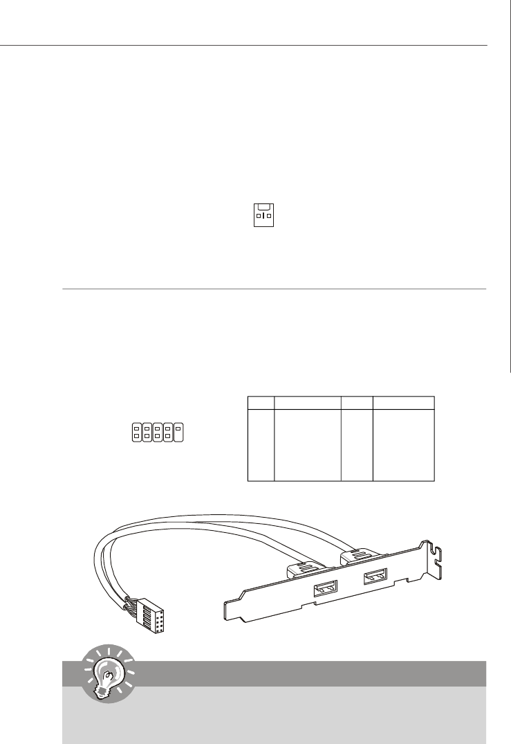
Front USB Connector: JUSB2, JUSB3
This connector, compliant with Intel® I/O Connectivity Design Guide, is ideal for con-
necting high-speed USB interface peripherals such as USB HDD, digital cameras,
MP3 players, printers, modems and the like.
PIN SIGNAL PIN SIGNAL
1VCC 2 VCC
3USB0- 4 USB1-
5USB0+ 6 USB1+
7GND 8 GND
9Key (no pin) 10 NC
Pin Definition
Important
Note that the pins of VCC and GND must be connected correctly to avoid
possible damage.
USB 2.0 Bracket
(Optional)
Chassis Intrusion Switch Connector: INTRUDER
This connector connects to the chassis intrusion switch cable. If the chassis is
opened, the chassis intrusion mechanism will be activated. The system will record
this status and show a warning message on the screen. To clear the warning, you
must enter the BIOS utility and clear the record.
INTRUDER
2
CINTRU
GND
1
1
2
9
10
JUSB2/3
PDF created with pdfFactory Pro trial version www.pdffactory.com
2-14
MS-96C8 Server Board
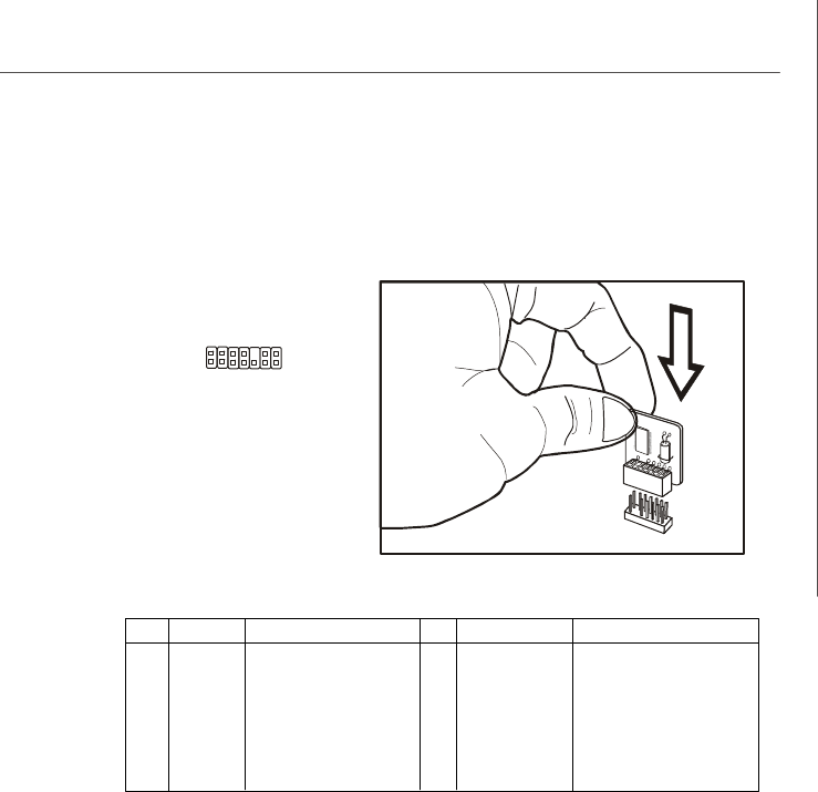
SPI Flash ROM Connector: J2
This connector is used to flash SPI flash ROM.
Pin Description Pin Description
1+3.3V DUAL 2 +3.3V DUAL
3 SPI_MISO 4 SPI_MOSI
5 SPI_CS0# 6 SPI_CLK
7GND 8 GND
9SPI_HOLD# 10 NC
Pin Definition
I2C Bus Connector: JSMBUS1
This connector, known as I2C, is for users to connect System Management Bus
(SMBus) interface.
PIN SIGNAL
1SMB Clock
2SMB Data
3PS Alert
4GND
5+3.3V
Pin Definition
JSMBUS1
51
1
J2
2
9
10
ME Enable/Disable Header: JGPIO33
This connector is provided for factory use only.
JGPIO33
GNDGPIO33
1
PDF created with pdfFactory Pro trial version www.pdffactory.com
2-15
Hardware Setup
TPM Connector: JTPM1 (Optional)
This connector connects to an optional TPM (Trusted Platform Module). Please refer
to the TPM security platform manual for more details.
PIN SIGNAL DESCRIPTION PIN SIGNAL DESCRIPTION
1LCLK LPC clock 2 +3.3V DUAL 3.3V standby power
3 LRST# LPC reset 4 +3.3V 3.3V power
5LAD0 LPC address & data pin0 6 SIRQ Serial IRQ
7LAD1 LPC address & data pin1 8 +5V 5V power
9LAD2 LPC address & data pin2 10 KEY No pin
11 LAD3 LPC address & data pin3 12 GND Ground
13 LFRAME#LPC Frame 14 GND Ground
2
1
14
13
JTPM1
PDF created with pdfFactory Pro trial version www.pdffactory.com
2-16
MS-96C8 Server Board
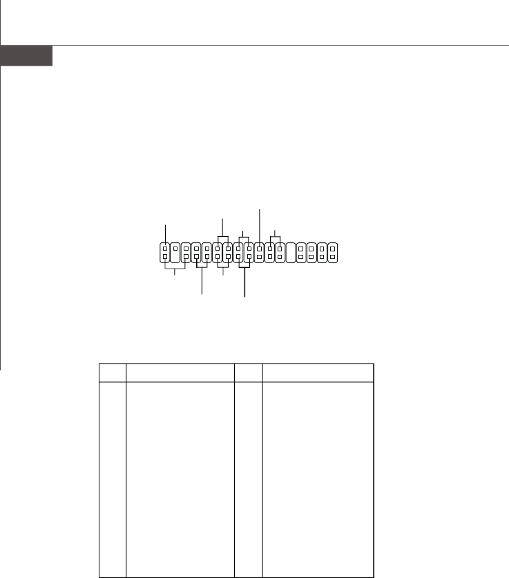
Front Panel Connector: JSSI1
The mainboard provides one front panel connector for electrical connection to the
front panel switches and LEDs.
Pin Description Pin Description
1 Power LED + 2 +5VSB
3 Key 4 NC
5 Power LED - 6 NC
7 HDD Activity LED + 8 System Status LED +
9 HDD Activity LED - 10 System Status LED -
11 Power Switch+ 12 LAN2 Activity LED +
13 Power Switch- 14 LAN2 Activity LED -
15 Reset Switch+ 16 SMBus DAT
17 Reset Switch- 18 SMBus CLK
19 Buzzer+ 20 Chassis Intrusion
21 Buzzer- 22 LAN1 Activity LED +
23 NMI to CPU Switch 24 LAN1 Activity LED -
25 Key 26 Key
27 ID LED+ 28 SGPIO Clock
29 ID LED- 30 SGPIO Load
31 ID# 32 SGPIO Dataout 0
33 GND 34 SGPIO Dataout 1
JSSI1 Pin Definition
JSSI1 34
Standby
Power (5V)
Power LED
HDD
LED Reset Switch
Power
Switch
Gigabit
LAN2 LED Gigabit
LAN1 LEDSMBus
Chassis
Intruder
33
2
1
PDF created with pdfFactory Pro trial version www.pdffactory.com
2-17
Hardware Setup
Jumper
Clear CMOS Jumper: CLR_CMOS
There is a CMOS RAM onboard that has a power supply from an external battery to
keep the data of system configuration. With the CMOS RAM, the system can auto-
matically boot OS every time it is turned on. If you want to clear the system configuration,
set the jumper to clear data.
CLR_CMOS
1
Important
You can clear CMOS by shorting 2-3 pin while the system is off. Then return
to 1-2 pin position. Avoid clearing the CMOS while the system is on; it will
damage the mainboard.
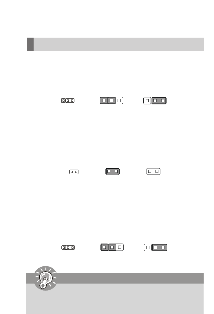
BIOS Recovery Jumper: RECOVERY
Users can short connect pin#2-3 to recover the system BIOS with a Recovery
Floppy. When the system is done with the job, the buzzer will beep to remind the user
to set the jumper to its normal state (pin#1-2 short connected).
Keep Data
1 3
Clear Data
1 3
RECOVERY
1
Normal
1 3
Recovery
1 3
BIOS Write Protect Jumper: JBIOS_WP
This jumper is used to enable/disable the BIOS flash. When you intend to update the
BIOS code, uncap this jumper first. Under normal operation, we suggest that you
disable the BIOS flash by capping this jumper to protect the system BIOS from virus
infection.
Enable BIOS FlashDisable BIOS Flash
JBIOS_WP
PDF created with pdfFactory Pro trial version www.pdffactory.com
2-18
MS-96C8 Server Board
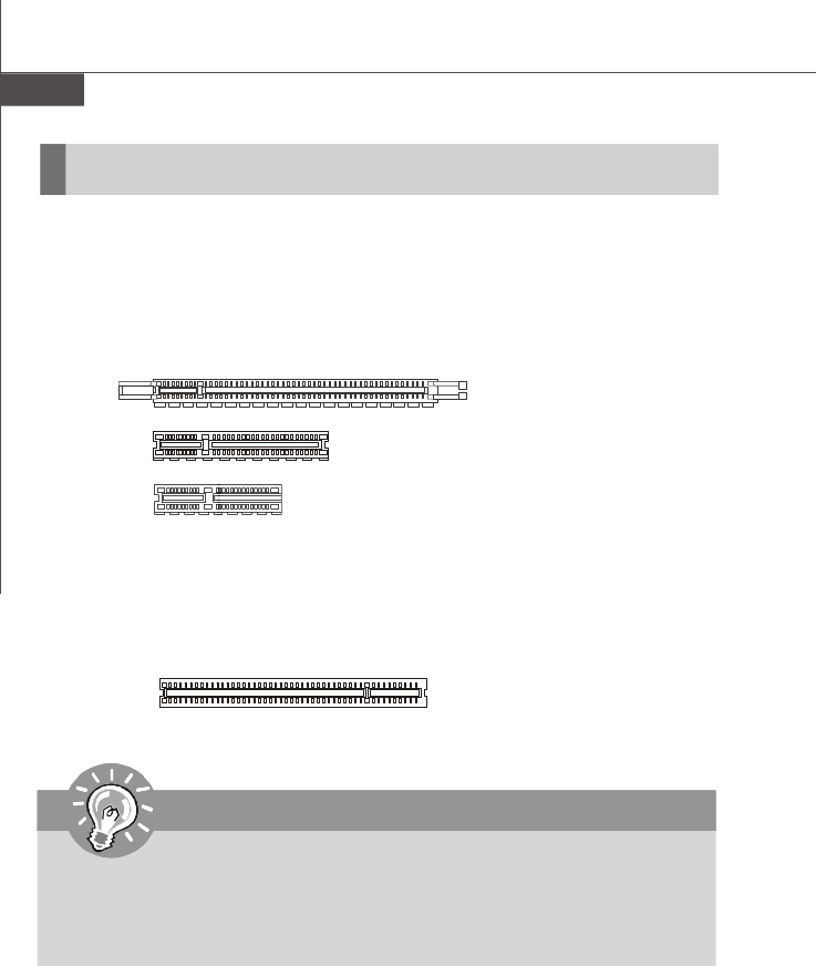
Slot
PCI (Peripheral Component Interconnect) Express Slot
The PCI Express slot supports the PCI Express interface expansion card.
The PCI Express 2.0 x16 slot supports up to 8.0 GB/s transfer rate.
The PCI Express 2.0 x8 slot supports up to 4.0 GB/s transfer rate.
The PCI Express 2.0 x4 slot supports up to 2.0 GB/s transfer rate.
PCI (Peripheral Component Interconnect) Slot
The PCI slot supports LAN card, SCSI card, USB card, and other add-on cards that
comply with PCI specifications.
PCI Express x16 Slot
32-bit PCI Slot
PCI Express x8 Slot
Important
When adding or removing expansion cards, make sure that you unplug the
power supply first. Meanwhile, read the documentation for the expansion card
to configure any necessary hardware or software settings for the expansion
card, such as jumpers, switches or BIOS configuration.
PCI Express x4 Slot
PDF created with pdfFactory Pro trial version www.pdffactory.com

3-1
BIOS Setup
Chapter 3
BIOS Setup
This chapter provides information on the BIOS Setup
program and allows you to configure the system for
optimum use.
You may need to run the Setup program when:
²An error message appears on the screen during the
system booting up, and requests you to run SETUP.
²You want to change the default settings for cus-
tomized features.
PDF created with pdfFactory Pro trial version www.pdffactory.com

3-2
MS-96C8 Server Board
Entering Setup
Important
1.The items under each BIOS category described in this chapter are under
continuous update for better system performance. Therefore, the descrip-
tion may be slightly different from the latest BIOS and should be held for
reference only.
2.Upon boot-up, the 1st line appearing after the memory count is the BIOS
version. It is usually in the format:
A96C8IMS V1.0 022709 where:
1st digit refers to BIOS maker as A = AMI, W = AWARD, and P =
PHOENIX.
2nd - 5th digit refers to the model number.
6th digit refers to the chipset as I = Intel, N = nVidia, and V = VIA.
7th - 8th digit refers to the customer as MS = all standard customers.
V1.0 refers to the BIOS version.
022709 refers to the date this BIOS was released.
Power on the computer and the system will start POST (Power On Self Test) process.
When the message below appears on the screen, press <Del> key to enter Setup.
Press Del to enter SETUP
If the message disappears before you respond and you still wish to enter Setup,
restart the system by turning it OFF and On or pressing the RESET button. You may
also restart the system by simultaneously pressing <Ctrl>, <Alt>, and <Delete> keys.
PDF created with pdfFactory Pro trial version www.pdffactory.com
3-3
BIOS Setup
Getting Help
After entering the Setup menu, the first menu you will see is the Main Menu.
Main Menu
The main menu lists the setup functions you can make changes to. You can use the
arrow keys ( -¯ ) to select the item. The on-line description of the highlighted setup
function is displayed at the bottom of the screen.
Sub-Menu
If you find a right pointer symbol (as shown in the right view)
appears to the left of certain fields that means a sub-menu can
be launched from this field. A sub-menu contains additional
options for a field parameter. You can use arrow keys ( -¯ ) to highlight the field and
press <Enter> to call up the sub-menu. Then you can use the control keys to enter
values and move from field to field within a sub-menu. If you want to return to the
main menu, just press the <Esc >.
General Help <F1>
The BIOS setup program provides a General Help screen. You can call up this screen
from any menu by simply pressing <F1>. The Help screen lists the appropriate keys
to use and the possible selections for the highlighted item. Press <Esc> to exit the
Help screen.
Control Keys
<->Move to the previous item
<¯>Move to the next item
<¬>Move to the item in the left hand
<®>Move to the item in the right hand
<Enter> Select the item
<Esc> Jumps to the Exit menu or returns to the main menu from a
submenu
<+/PU> Increase the numeric value or make changes
<-/PD> Decrease the numeric value or make changes
<F9> Load Optimized Defaults
<F8> Load Fail-Safe Defaults
<F10> Save all the CMOS changes and exit
PDF created with pdfFactory Pro trial version www.pdffactory.com
3-4
MS-96C8 Server Board
The Menu Bar
Main
Use this menu for basic system configurations, such as time, date etc.
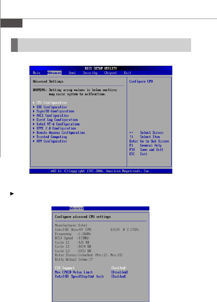
Advanced
Use this menu to set up the items of special enhanced features.
Boot
Use this menu to specify the priority of boot devices.
Security
Use this menu to set supervisor and user passwords.
Chipset
This menu controls the advanced features of the onboard Northbridge and Southbridge.
Exit
This menu allows you to load the BIOS default values or factory default settings into
the BIOS and exit the BIOS setup utility with or without changes.
PDF created with pdfFactory Pro trial version www.pdffactory.com
3-5
BIOS Setup
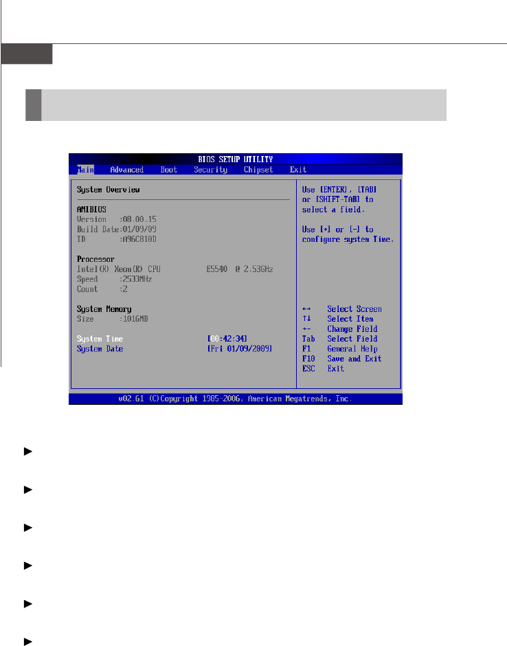
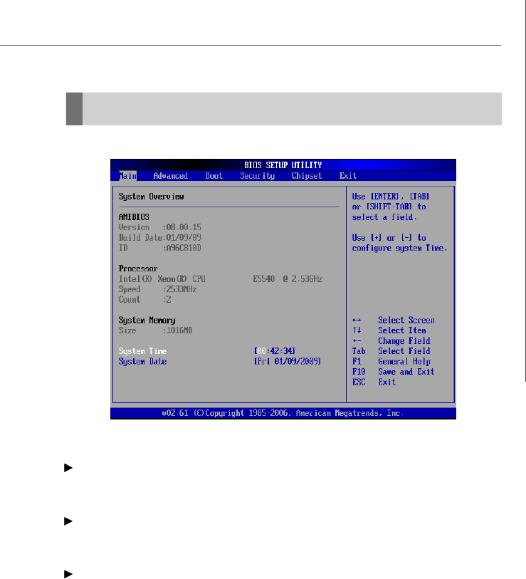
Main
AMI BIOS, Processor, System Memory
These items show the firmware and hardware specifications of your system. Read
only.
System Time
This setting allows you to set the system time. The time format is <Hour> <Minute>
<Second>.
System Date
This setting allows you to set the system date. The date format is <Day>, <Month>
<Date> <Year>.
PDF created with pdfFactory Pro trial version www.pdffactory.com

3-7
BIOS Setup
C1E Support
When the C1E Support (Enhanced Halt Powerdown State) is enabled, the proc-
essor will transition to a lower core to bus ratio and lower voltage ID driven by
the processor to the voltage regulator before entering Halt Powerdown State
(C1). Not all porcessors support Enhanced Halt Powerdown State (C1E).
Max CPUID Value Limit
The Max CPUID Value Limit BIOS feature allows you to circumvent problems
with older operating systems that do not support the Intel Pentium 4 processor
with Hyper-Threading Technology. When enabled, the processor will limit the
maximum CPUID input value to 03h when queried, even if the processor sup-
ports a higher CPUID input value. When disabled, the processor will return the
actual maximum CPUID input value of the processor when queried.
Intel(R) SpeedStep(tm) Tech
EIST (Enhanced Intel SpeedStep Technology) allows the system to dynamically
adjust processor voltage and core frequency, which can result in decreased
average power consumption and decreased average heat production.
PDF created with pdfFactory Pro trial version www.pdffactory.com
3-8
MS-96C8 Server Board
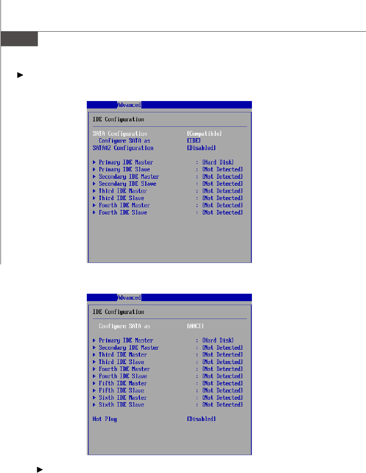
IDE Configuration
With “Configure SATA as ” set to [IDE]
With “Configure SATA as ” set to [AHCI]
SATA Configuration, SATA#2 Configuration
This setting specifies SATA controller mode. Please note that Pre-Win2K OS do
not work in Enhanced mode.
[Compatible] SATA and PATA drives are auto-detected and placed in Legacy
mode.
[Enhanced] SATA and PATA drives are auto-detected and placed in Native
IDE mode.
PDF created with pdfFactory Pro trial version www.pdffactory.com
3-9
BIOS Setup
Configure SATA ass
This setting specifies the operation mode of the onboard SATA drive. Setting
options: [IDE], [AHCI], [RAID].
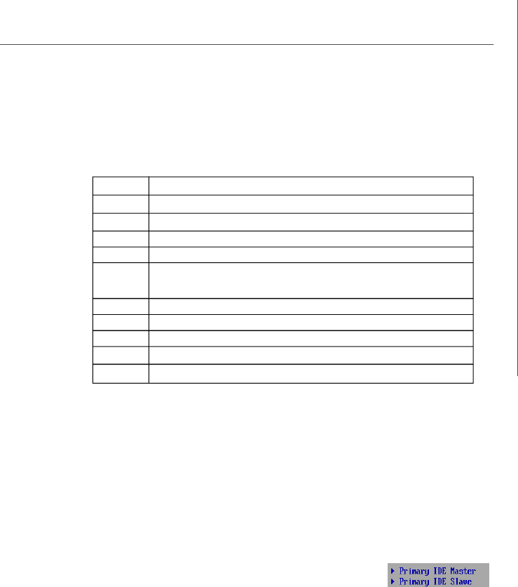
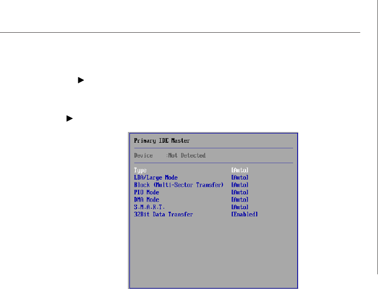
Primary/Secondary/Third/Fourth/Fifth/Sixth IDE Master/Slave
[Type] Press PgUp/<+> or PgDn/<-> to select
[Manual], [None] or [Auto] type. Note that the
specifications of your drive must match with
the drive table. The hard disk will not work
properly if you enter improper information for
this category. If your hard disk drive type is
not matched or listed, you can use [Manual] to
define your own drive type manually.
[LBA/Large Mode] Enabling LBA causes Logical Block Ad-
dressing to be used in place of Cylinders,
Heads and Sectors
[Block(Multi-Sector Transfer)]Any selection except Disabled determines
the number of sectors transferred per block
[PIO Mode] Indicates the type of PIO (Programmed Input/
Output)
[DMA Mode] Indicates the type of Ultra DMA
[S.M.A.R.T.] This allows you to activate the S.M.A.R.T.
(Self-Monitoring Analysis & Reporting
Technology) capability for the hard disks. S.
M.A.R.T is a utility that monitors your disk sta
tus to predict hard disk failure. This gives you
an opportunity to move data from a hard disk
that is going to fail to a safe place before the
hard disk becomes offline.
[32 Bit Data Transfer] Enables 32-bit communication between
CPU and IDE device
PDF created with pdfFactory Pro trial version www.pdffactory.com
3-10
MS-96C8 Server Board
Hot Plug
This setting enables/disables the hot plug function of the onboard SATA de-
vices and only appears when Configure SATA as is set to [AHCI] or [RAID].
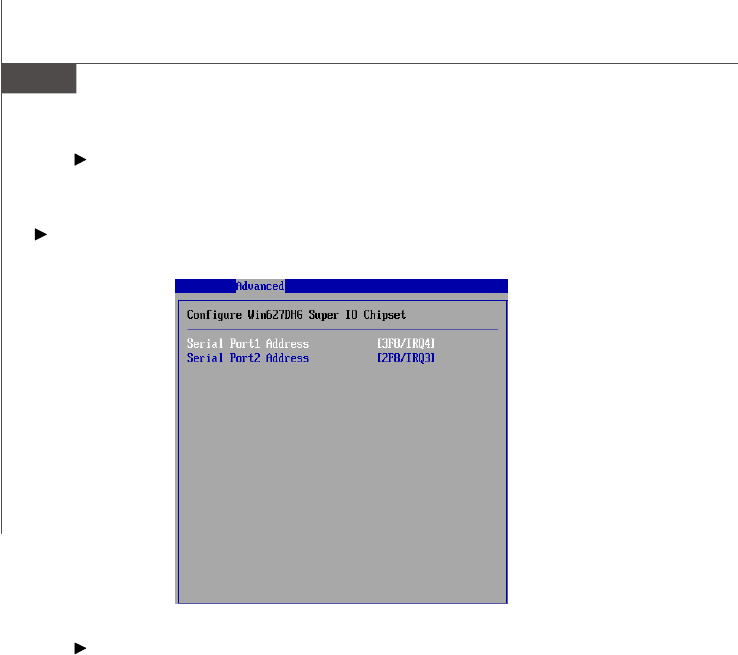
Super IO Configuration
Serial Port 1 Address, Serial Port 2 Address
Select an address and a corresponding interrupt for the serial port 1/2.
PDF created with pdfFactory Pro trial version www.pdffactory.com
3-11
BIOS Setup
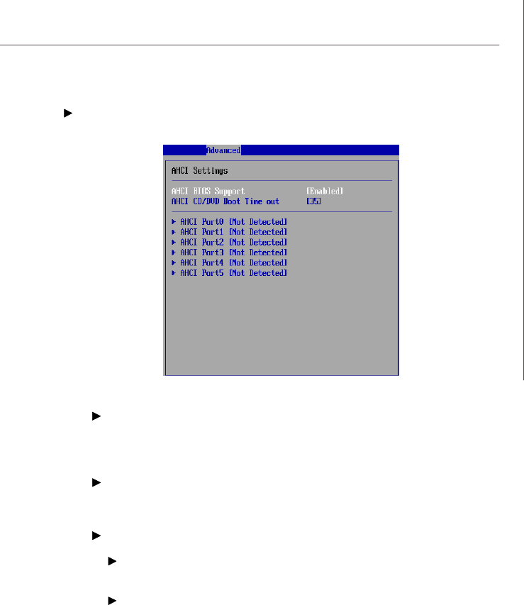
AHCI Configuration
AHCI BIOS Support
This BIOS feature controls the SATA controller's AHCI (Advanced Host Control-
ler Interface) functionality. It is a new interface specification that enables ad-
vanced SATA features like Native Command Queuing (NCQ) and hot-plugging.
AHCI CD/DVD Boot Time Out
This setting specifies the delay of the AHCI CD/DVD drivers loading for multi-
read/write. Changing the value to 0 will grant no delay at boot.
AHCI Port 0/1/2/3/4/5
SATA Port 0
This setting controls the SATA port 0.
S.M.A.R.T.
This allows you to activate the S.M.A.R.T. (Self-Monitoring Analysis & Re-
porting Technology) capability for the hard disks. S.M.A.R.T is a utility that
monitors your disk status to predict hard disk failure. This gives you an
opportunity to move data from a hard disk that is going to fail to a safe place
before the hard disk becomes offline.
PDF created with pdfFactory Pro trial version www.pdffactory.com
3-14
MS-96C8 Server Board
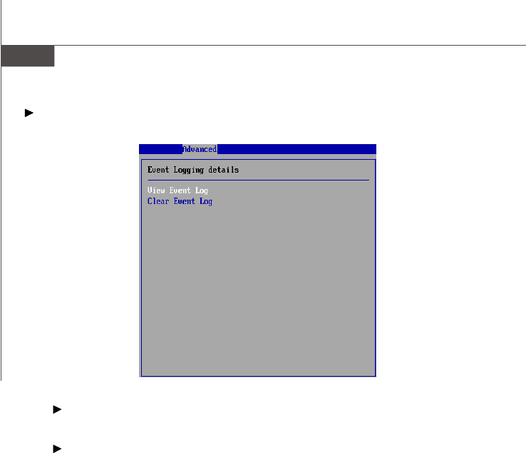
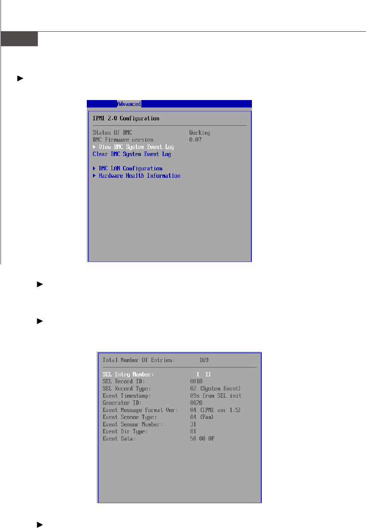
IPMI 2.0 Configuration
Status of BMC, BMC Firmware Version
These settings show the status of the BMC (Baseboard Management
Controller) chip and its firmware version. Read only.
View BMC System Event Log
Use this function to view system event logs recorded by BMC.
Clear BMC System Event Log
Use this function to clear system event logs recorded by BMC.
PDF created with pdfFactory Pro trial version www.pdffactory.com
3-15
BIOS Setup
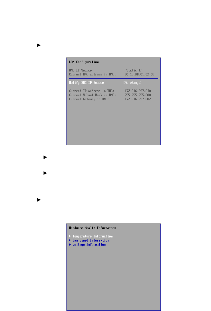
BMC LAN Configuration
Notify BMC IP Source
Use this setting to check the BMC IP source.
Current IP Address in BMC, Current Subnet Mask in BMC, Cur-
rent Gateway in BMC
Use these settings to view the IP address, subnet mask, and gateway in
BMC.
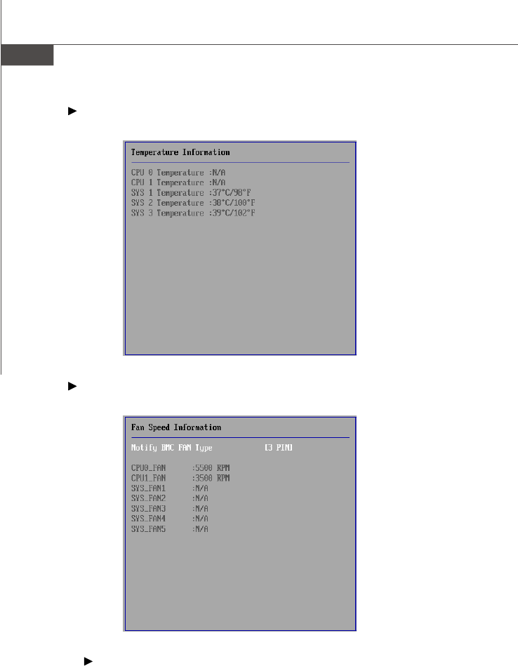
Hardware Health Information
These items display the current status of all of the monitored hardware de-
vices/components such as voltages, temperatures and all fans’ speeds.
PDF created with pdfFactory Pro trial version www.pdffactory.com
3-17
BIOS Setup
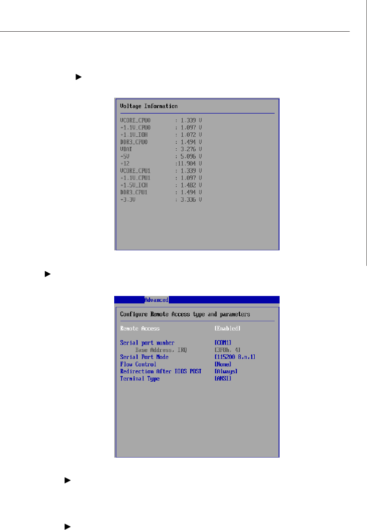
Voltage Information
Remote Access Configuration
Remote Access
The setting enables/disables the remote access function. When set to [Enabled],
users may configure the following settings for remote access type and
parameters.
Serial Port Number, Base Address, IRQ, Serial Port Mode
Use these settings to configure ports for remote access.
PDF created with pdfFactory Pro trial version www.pdffactory.com
3-18
MS-96C8 Server Board
Flow Control
Flow control is the process of managing the rate of data transmission between
two nodes. It’s the process of adjusting the flow of data from one device to
another to ensure that the receiving device can handle all of the incoming data.
This is particularly important where the sending device is capable of sending
data much faster than the receiving device can receive it.
Redirection After BIOS POST
This setting determines whether or not to keep terminals’ console redirection
running after the BIOS POST has booted.
Terminal Type
To operate the system’s console redirection, you need a terminal supporting
ANSI terminal protocol and a RS-232 null modem cable connected between the
host system and terminal(s). This setting specifies the type of terminal device
for console redirection.
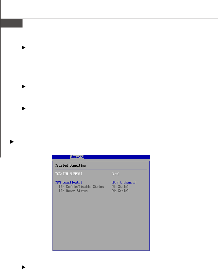
Trusted Computing
TCG/TPM Support
This setting controls the Trusted Platform Module (TPM) designed by the Trusted
Computing Group (TCG). TPMs are special-purpose integrated circuits (ICs)
built into a variety of platforms to enable strong user authentication and ma-
chine attestation—essential to prevent inappropriate access to confidential
and sensitive information and to protect against compromised networks. TPM
Services is now a new feature set in Windows Server "Longhorn" and Win-
dows Vista.
PDF created with pdfFactory Pro trial version www.pdffactory.com
3-19
BIOS Setup
TPM Deactivated
When the TPM is cleared, all the keys you previously had stored on your vault
will be lost. You should create an archive of your TPM Keys before clearing the
TPM. To recover your TPM keys, you will need to restore your keys from an
archive.
TPM Enable/Disable Status
This setting displays the TPM enable/disable status. Read only.
TPM Owner Status
This setting shows the TPM ownership. Read only.
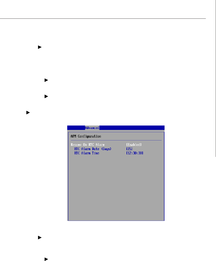
APM Configuration
Resume On RTC Alarm
When [Enabled], your can set the date and time at which the RTC (real-time
clock) alarm awakens the system from suspend mode.
RTC Alarm Date (Days), RTC Alarm Time
If Resume On RTC Alarm is set to [Enabled], the system will automatically
resume (boot up) on a specific date/hour/minute/second specified in these
fields (using the <+> and <-> to select the date & time settings). Available
settings for each item are:
Date 01 ~ 31, Every Day
Time (HH:MM:SS) 00 ~ 23 : 00 ~ 59 : 00 ~ 59
PDF created with pdfFactory Pro trial version www.pdffactory.com

3-21
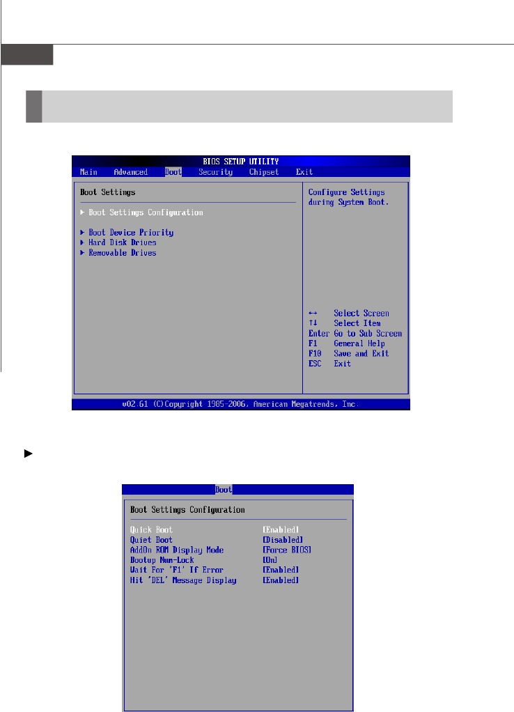
BIOS Setup
Quick Boot
Enabling this setting will cause the BIOS power-on self test routine to skip some
of its tests during bootup for faster system boot.
Quiet Boot
This BIOS feature determines if the BIOS should hide the normal POST mes-
sages with the motherboard or system manufacturer's full-screen logo.
When it is enabled, the BIOS will display the full-screen logo during the boot-up
sequence, hiding normal POST messages.
When it is disabled, the BIOS will display the normal POST messages, instead of
the full-screen logo.
Please note that enabling this BIOS feature often adds 2-3 seconds of delay to
the booting sequence. This delay ensures that the logo is displayed for a
sufficient amount of time. Therefore, it is recommended that you disable this
BIOS feature for a faster boot-up time.
AddOn ROM Display Mode
This item is used to determine the display mode when an optional ROM is
initialized during POST. When set to [Force BIOS], the display mode used by AMI
BIOS is used. Select [Keep Current] if you want to use the display mode of
optional ROM.
Bootup Num-Lock
This setting is to set the Num Lock status when the system is powered on.
Setting to [On] will turn on the Num Lock key when the system is powered on.
Setting to [Off] will allow users to use the arrow keys on the numeric keypad.
Wait For ‘F1’ If Error
When this setting is set to [Enabled] and the boot sequence encounters an
error, it asks you to press F1. If disabled, the system continues to boot without
waiting for you to press any keys.
Hit ‘DEL’ Message Display
Set this option to [Disabled] to prevent the message as follows:
Hit Del if you want to run setup
It will prevent the message from appearing on the first BIOS screen when the
computer boots. Set it to [Enabled] when you want to run the BIOS Setup Utility.
PDF created with pdfFactory Pro trial version www.pdffactory.com
3-22
MS-96C8 Server Board
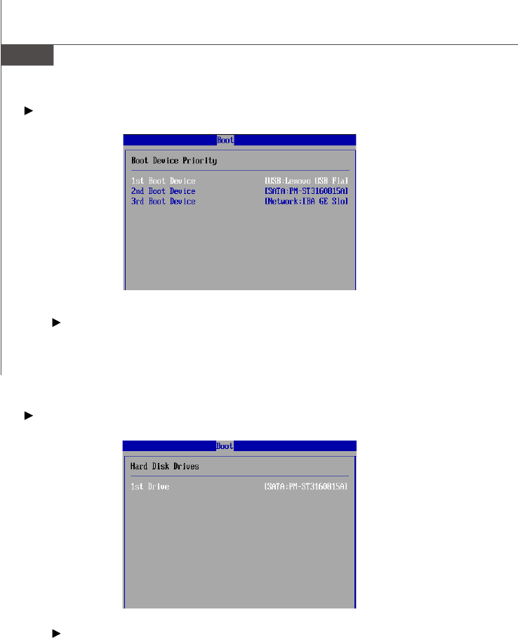
Boot Device Priority
1st Boot Device, 2nd Boot Device, 3rd Boot Device
The items allow you to set the sequence of boot devices where BIOS attempts
to load the disk operating system. First press <Enter> to enter the sub-menu.
Then you may use the arrow keys ( -¯ ) to select the desired device, then
press <+>, <-> or <PageUp>, <PageDown> key to move it up/down in the
priority list.
Hard Disk Drives
1st Drive
The items allow you to set the sequence of HDD devices where BIOS attempts
to load the disk operating system. First press <Enter> to enter the sub-menu.
Then you may use the arrow keys ( -¯ ) to select the desired device, then
press <+>, <-> or <PageUp>, <PageDown> key to move it up/down in the
priority list.
PDF created with pdfFactory Pro trial version www.pdffactory.com
3-23
BIOS Setup
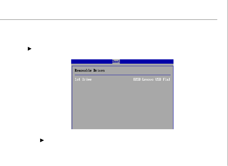
Removable Drives
1st Drive
This setting allows users to set the priority of the removable devices. First
press <Enter> to enter the sub-menu. Then you may use the arrow keys ( -¯ )
to select the desired device, then press <+>, <-> or <PageUp>, <PageDown>
key to move it up/down in the priority list.
PDF created with pdfFactory Pro trial version www.pdffactory.com
3-24
MS-96C8 Server Board
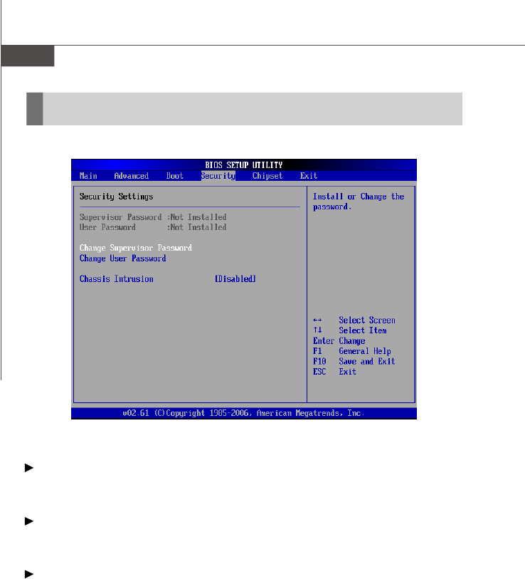
Security
Supervisor Password / Change Supervisor Password
Supervisor Password controls access to the BIOS Setup utility. These settings allow
you to set or change the supervisor password.
User Password / Change User Password
User Password controls access to the system at boot. These settings allow you to
set or change the user password.
Chassis Intrusion
The field enables or disables the feature of recording the chassis intrusion status
and issuing a warning message if the chassis is once opened. To clear the warning
message, set the field to [Reset]. The setting of the field will automatically return to
the default value later.
PDF created with pdfFactory Pro trial version www.pdffactory.com
3-26
MS-96C8 Server Board
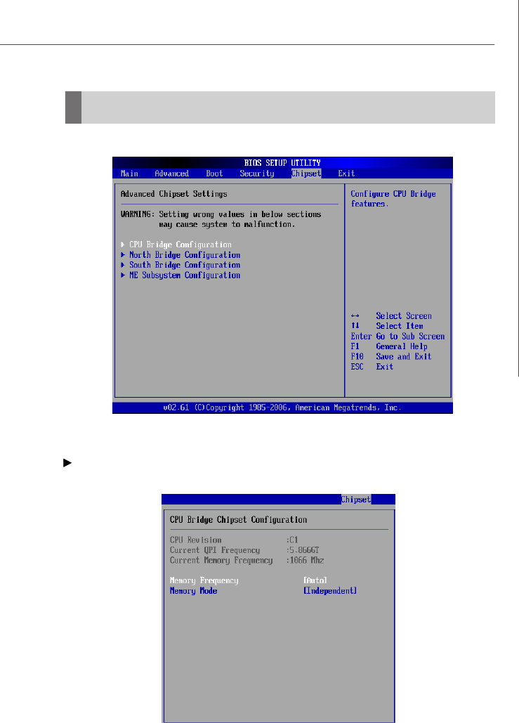
Memory Frequency
This item allows you to select the memory frequency.
Memory Mode
This setting specifies the memory mode.
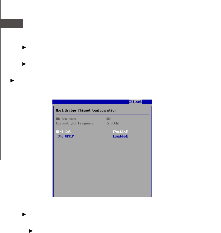
North Bridge Configuration
This sub-menu shows the north bridge information.
MINI SAS
This setting enables/disables the onboard mini SAS controller.
SAS OPROM
This setting enables/disables the initialization of the SAS boot ROM during
bootup. Selecting [Disabled] will speed up the boot process.
PDF created with pdfFactory Pro trial version www.pdffactory.com
3-27
BIOS Setup
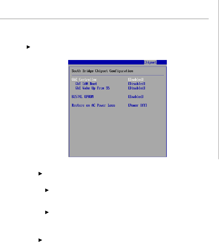
South Bridge Configuration
GbE Controller
These settings disable/enable the specified LAN controllers.
GbE LAN Boot, 82574L OPROM
The items enable or disable the initialization of the onboard LAN Boot ROMs
during bootup. Selecting [Disabled] will speed up the boot process.
GbE Wake Up From S5
This field specifies whether the system will be awakened from power sav-
ing modes when activity or input signal of the onboard Gigabit LAN is
detected.
Restore on AC Power Loss
This setting specifies whether your system will reboot after a power failure or
interrupt occurs. Available settings are:
[Power Off] Leaves the computer in the power off state.
[Power On] Leaves the computer in the power on state.
[Last State] Restores the system to the previous status before power
failure or interrupt occurred.
PDF created with pdfFactory Pro trial version www.pdffactory.com
3-28
MS-96C8 Server Board
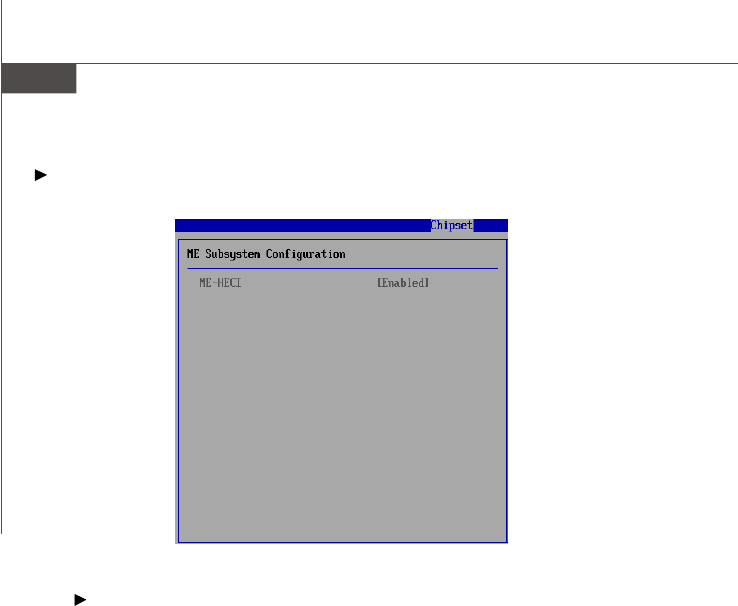
ME Subsystem Configuration
ME-HECI
This setting enables/disables ME-HECI. Host Embedded Controller Interface
(HECI) driver is a software interface that is used to communicate to the AMT
subsystem (Management Engine) to access AMT capabilities. Communication
between the local host operating system (OS) and the ME is accomplished by
means of the HECI driver. HECI is bi-directional, as either the host OS or Intel
AMT firmware can initiate transactions.
PDF created with pdfFactory Pro trial version www.pdffactory.com
3-29
BIOS Setup
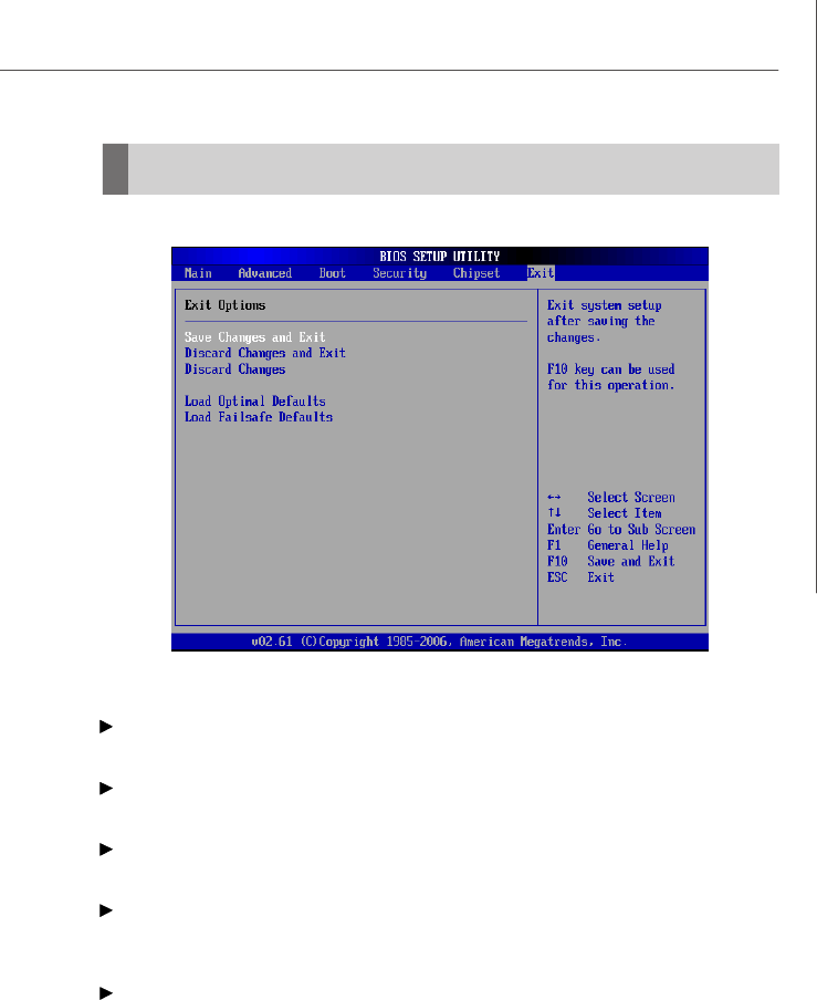
Exit
Save Changes and Exit
Save changes to CMOS and exit the Setup Utility.
Discard Changes and Exit
Abandon all changes and exit the Setup Utility.
Discard Changes
Abandon all changes and continue with the Setup Utility.
Load Optimal Defaults
Use this menu to load the default values set by the mainboard manufacturer specifi-
cally for optimal performance of the mainboard.
Load Failsafe Defaults
Use this menu to load the default values set by the BIOS vendor for stable system
performance.
PDF created with pdfFactory Pro trial version www.pdffactory.com


A-2
MS-96C8 Server Board
Introduction
Important
The least number of hard drives for RAID 0, RAID 1, Recovery or Matrix
mode is 2. The least number of hard drives for RAID 10 mode is 4. And the
least number of hard drives for RAID 5 mode is 3.
All the information/ volumes/ pictures listed in your system might differ from
the illustrations in this appendix.
The ICH10R provides a hybrid solution that combines 6 independent SATAII ports for
support of up to 6 Serial ATAII (Serial ATAII RAID) drives.
Serial ATAII (SATAII) is the latest generation of the ATA interface. SATA hard drives
deliver blistering transfer speeds up to 3 Gb/s. Serial ATA uses long, thin cables,
making it easier to connect your drive and improving the airflow inside your PC. The
most outstanding features are:
1. Supports 3 Gb/s transfers with CRC error checking.
2. Supports Hot-plug-n-play feature.
3. Data handling optimizations including tagged command queuing, elevator
seek and packet chain command.
Intel® ICH10R offers RAID level 0 (Striping), RAID level 1 (Mirroring and Duplexing),
RAID level 5 (Block Interleaved Distributed Parity), RAID level 10 (A Stripe of Mirrors)
, Intel® Martix Storage Technology and Intel® Rapid Recover Technology.
RAID 0 breaks the data into blocks which are written to separate hard drives. Spreading
the hard drive I/O load across independent channels greatly improves I/O performance.
RAID 1 provides data redundancy by mirroring data between the hard drives and
provides enhanced read performance.
RAID 5 Provides data striping at the byte level and also stripe error correction
information. This results in excellent performance and good fault tolerance. Level 5 is
one of the most popular implementations of RAID.
RAID 10 Not one of the original RAID levels, multiple RAID 1 mirrors are created, and
a RAID 0 stripe is created over these.
Intel Matrix RAID Technology is the advanced ability for two RAID volumes to share
the combined space of two hard drives being used in unison.
Intel Rapid Recover Technology utilizes RAID 1 functionality to copy data from a
designated Master drive to a designated Recovery drive. The size of the Master drive
must be less than or equal to the size of the Recovery drive. When a Recovery
volume is created, complete capacity of the Master drive will be used as the Master
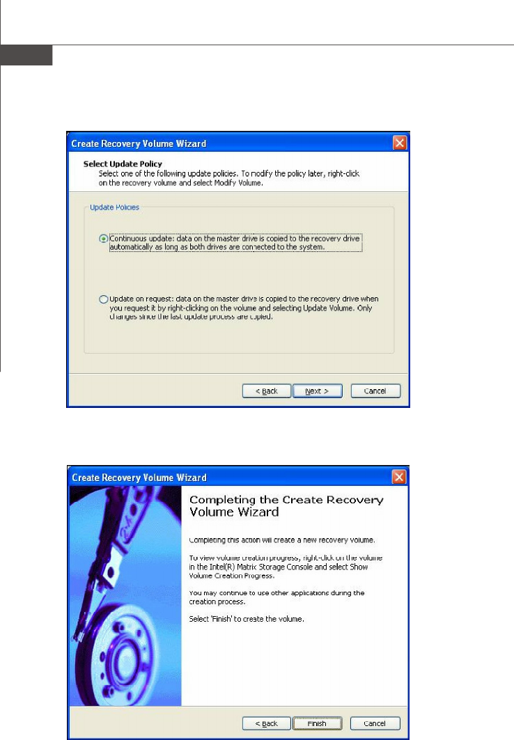
volume. Only one Recovery Volume can exist on a system. There are 2 methods of
updating the data on the Master to the Recovery drive. They are Continuous Update
Policy and On Request Update Policy.
PDF created with pdfFactory Pro trial version www.pdffactory.com
A-3
Intel ICH10R SATA RAID
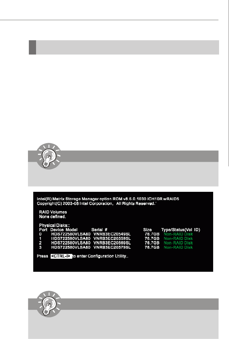
BIOS Configuration
After the above message shows, press <Ctrl> and <I> keys simultaneously to enter
the RAID Configuration Utility.
Important
The “Drvice Model”, “Serial #” and “Size” in the following example might be
different from your system.
Important
The following procedure is only available with a newly-built system or if you
are reinstalling your OS. It should not be used to migrate an existing system
to RAID.
The Intel Matrix Storage Manager Option ROM should be integrated with the system
BIOS on all motherboards with a supported Intel chipset. The Intel Matrix Stroage
Manager Option ROM is the Intel RAID implementation and provides BIOS and DOS
disk services. Please use <Ctrl> + <I> keys to enter the “Intel(R) RAID for Serial ATA”
status screen, which should appear early in system boot-up, during the POST
(Power-On Self Test). Also, you need to enable the RAID function in BIOS to create,
delete and reset RAID volumes.
Using the Intel Matrix Stroage Manager Option ROM
1. Creating, Deleting and Resetting RAID Volumes:
The Serial ATA RAID volume may be configured using the RAID Configuration utility
stored within the Intel RAID Option ROM. During the Power-On Self Test (POST), the
following message will appear for a few seconds:
PDF created with pdfFactory Pro trial version www.pdffactory.com
A-4
MS-96C8 Server Board
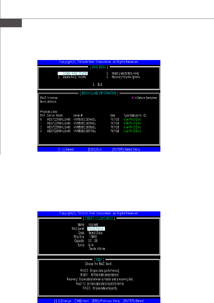
(1) Create RAID Volume
1. Select option 1 “Create RAID Volume” and press <Enter> key. The following
screen appears. Then in the Name field, specify a RAID Volume name and
then press the <TAB> or <Enter> key to go to the next field.
2. Use the arrow keys to select the RAID level best suited to your usage model
in RAID Level.
After pressing the <Ctrl> and <I> keys simultaneously, the following window will
appear:
PDF created with pdfFactory Pro trial version www.pdffactory.com
A-5
Intel ICH10R SATA RAID
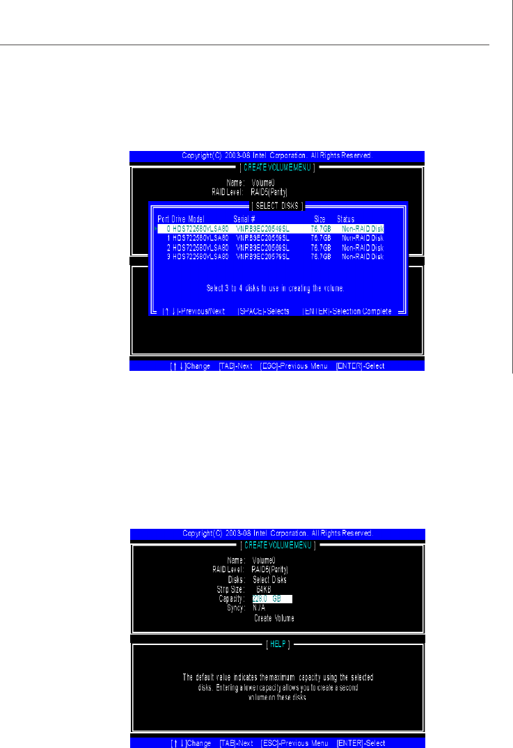
3. In the Disk field, press <Enter> key and the following screen appears. Use
<Space> key to select the disks you want to create for the RAID volume, then
click <Enter> key to finish selection.
4. Then select the strip value for the RAID array by using the “upper arrow” or
“down arrow” keys to scroll through the available values, and pressing the
<Enter> key to select and advance to the next field. The available values
range from 4KB to 128 KB in power of 2 increments. The strip value should be
chosen based on the planned drive usage. Here are some typical values:
RAID0 – 128KB
RAID10 – 64KB
RAID5 – 64KB
5. Then select the capacity of the volume in the Capacity field. The default
value is the maximum volume capacity of the selected disks.
PDF created with pdfFactory Pro trial version www.pdffactory.com
A-6
MS-96C8 Server Board
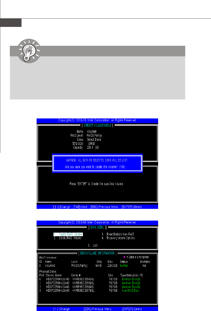
6.Then the following screen appears for you to confirm if you are sure to
create the RAID volume. Press <Y> to continue.
7.Then the following screen appears to indicate that the creation is finished.
Important
Since you want to create two volumes (Intel Matrix RAID Technology), this
default size (maximum) needs to be reduced. Type in a new size for the first
volume. As an example: if you want the first volume to span the first half of the
two disks, re-type the size to be half of what is shown by default. The second
volume, when created, will automatically span the remainder of two hard
drives.
PDF created with pdfFactory Pro trial version www.pdffactory.com
A-7
Intel ICH10R SATA RAID
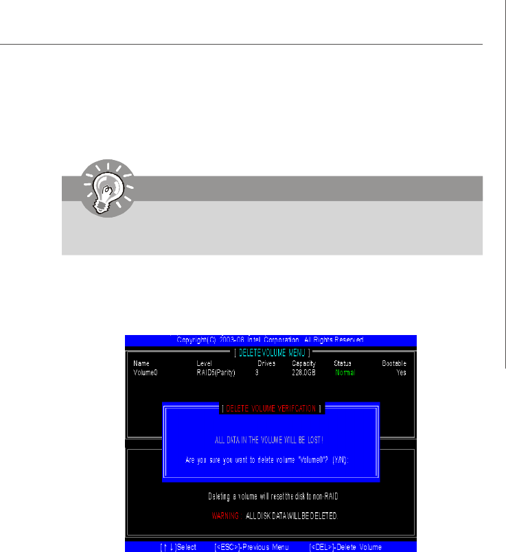
(2) Delete RAID Volume
Here you can delete the RAID volume, but please be noted that all data on RAID
drives will be lost.
Select option 2 Delete RAID Volume from the main menu window and press
<Enter> key to select a RAID volume for deletion. Then press <Delete> key to
delete the selected RAID volume. The following screen appears.
Press <Y> key to accept the volume deletion.
Important
If your system currently boots to RAID and you delete the RAID volume in the
Intel RAID Option ROM, your system will become unbootable.
PDF created with pdfFactory Pro trial version www.pdffactory.com
A-8
MS-96C8 Server Board
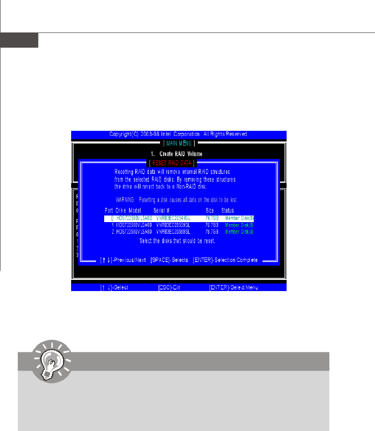
(3) Reset Disks to Non-RAID
Select option 3 Reset Disks to Non-RAID and press <Enter> to delete the RAID
volume and remove any RAID structures from the drives. The following screen
appears:
Press <Y> key to accept the selection.
Important
1. You will lose all data on the RAID drives and any internal RAID structures
when you perform this operation.
2. Possible reasons to ‘Reset Disks to Non-RAID’ could include issues such
as incompatible RAID configurations or a failed volume or failed disk.
PDF created with pdfFactory Pro trial version www.pdffactory.com
A-9
Intel ICH10R SATA RAID
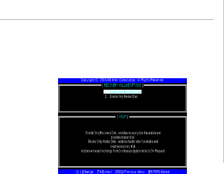
(4) Recovery Volume Options
Select option 4 Recovery Volume Options and press <Enter> to change recovery
volume mode. The following screen appears:
Recovery mode will change from Continuous Update to On-Request after you
enable “Only Recovery Disk” or “Only Master Disk”.
PDF created with pdfFactory Pro trial version www.pdffactory.com

A-10
MS-96C8 Server Board
Installing Driver
Install Driver in Windows Server 2008/2003
† New Windows Server 2008/2003 Installation
The following details the installation of the drivers while installing operating system.
1. When you start installing Windows Server 2008/2003, you may encounter a
message stating, “Setup could not determine the type of one or more mass
storage devices installed in your system”. If this is the case, then you are
already in the right place and are ready to supply the driver. For Windows
2003, if this is not the case, then press F6 when prompted at the beginning of
Windows setup.
2. Press the “S” key to select “Specify Additional Device”.
3. You should be prompted to insert a floppy disk containing the Intel® RAID
driver into the A: drive.
Important
Please follow the instruction below to make an “Intel® RAID Driver” for
yourself.
1. Insert the MSI CD into the CD-ROM drive.
2. Click the “Browse CD” on the Setup screen.
3.Copy all the contents in \\SATA2_RAID\f6flpy3288 (32 bits) or
\\SATA2_RAID\f6flpy6488 (64 bits) to a formatted floppy diskette.
4.The driver diskette for Intel® ICH10R RAID Controller is done.
4. During the Operating system installation, after selecting the location to install,
click on “Load Driver” button to install a third party SCSI or RAID driver.
5. When prompted, insert the floppy disk or media (CD/DVD or USB) you created
in step 3 and press Enter.
6. You should be shown a list of available SCSI Adapters.
7. Select the appropriate Intel RAID controller and press ENTER.
8. The next screen should confirm that you have selected the Intel® RAID
controller. Press ENTER again to continue.
9. You have successfully installed the Intel SATA RAID driver, and Windows
setup should continue.
10. Leave the disk in the floppy drive until the system reboots itself. Windows
setup will need to copy the files from the floppy again after the RAID volume
is formatted, and Windows setup starts copying files.\
PDF created with pdfFactory Pro trial version www.pdffactory.com
A-11
Intel ICH10R SATA RAID
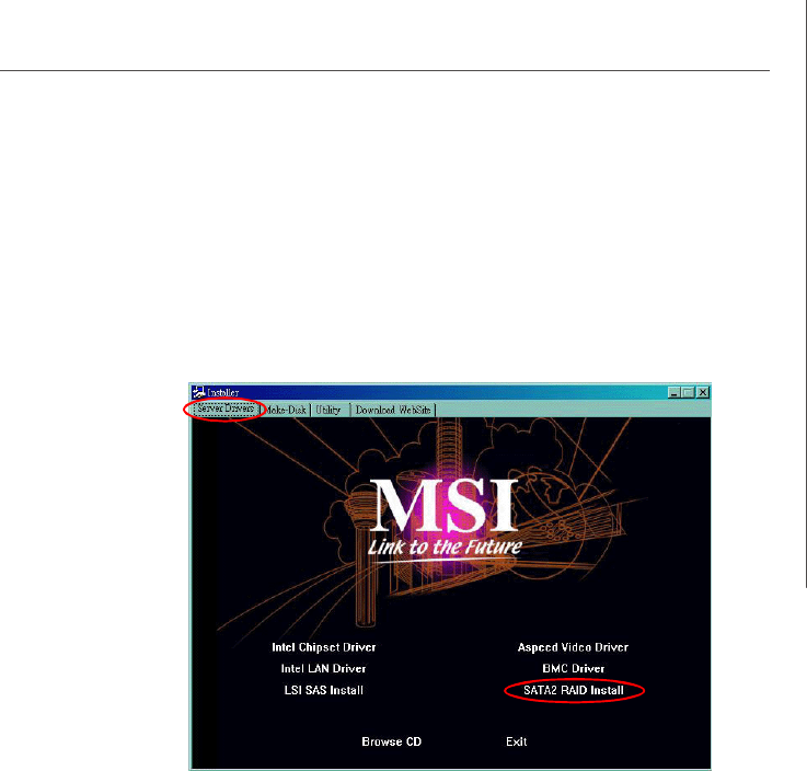
† Existing Windows Server 2008/2003 Driver Installation
1. Insert the MSI CD into the CD-ROM drive.
2. The CD will auto-run and the setup screen will appear.
3. Under the Server Drivers tab, click on SATA2 RAID Install.
4. The drivers will be automatically installed.
† Confirming Windows Server 2008/2003 Driver Installation
1. Under Windows Server 2008/2003, open the Control Panel from My Com-
puter followed by the System icon.
2. Choose the Hardware tab, then click the Device Manager tab.
3. Click the "+" in front of the SCSI and RAID Controllers hardware type. The
driver Intel(R) ICH10R SATA RAID Controller should appear.
PDF created with pdfFactory Pro trial version www.pdffactory.com
A-12
MS-96C8 Server Board
Install Intel Matrix Storage Console
The Intel Application Accelerator RAID Edition driver may be used to operate the hard
drive from which the system is booting or a hard drive that contains important data.
For this reason, you cannot remove or un-install this driver from the system after
installation; however, you will have the ability to un-install all other non-driver
components.
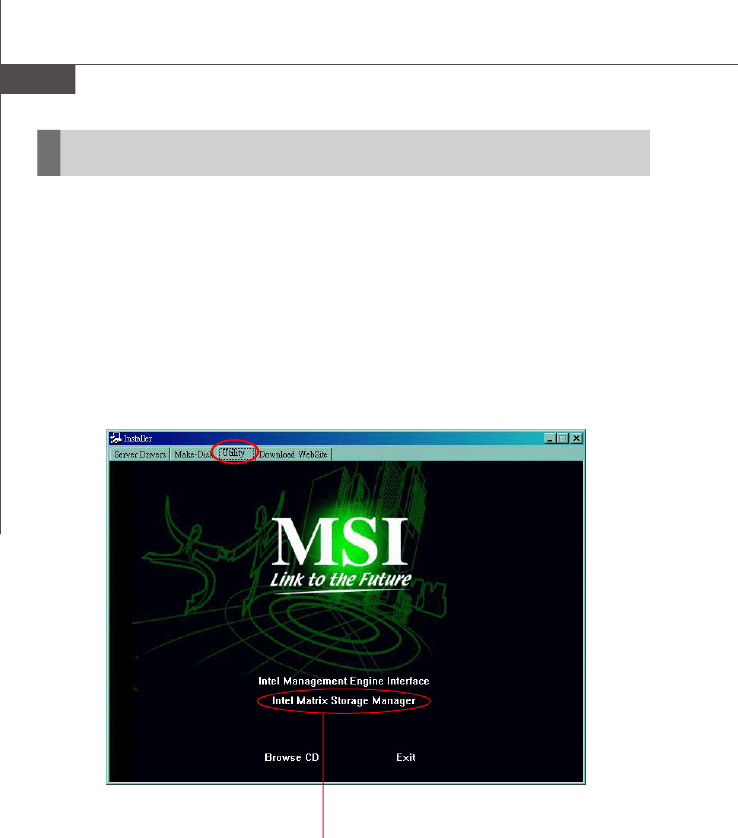
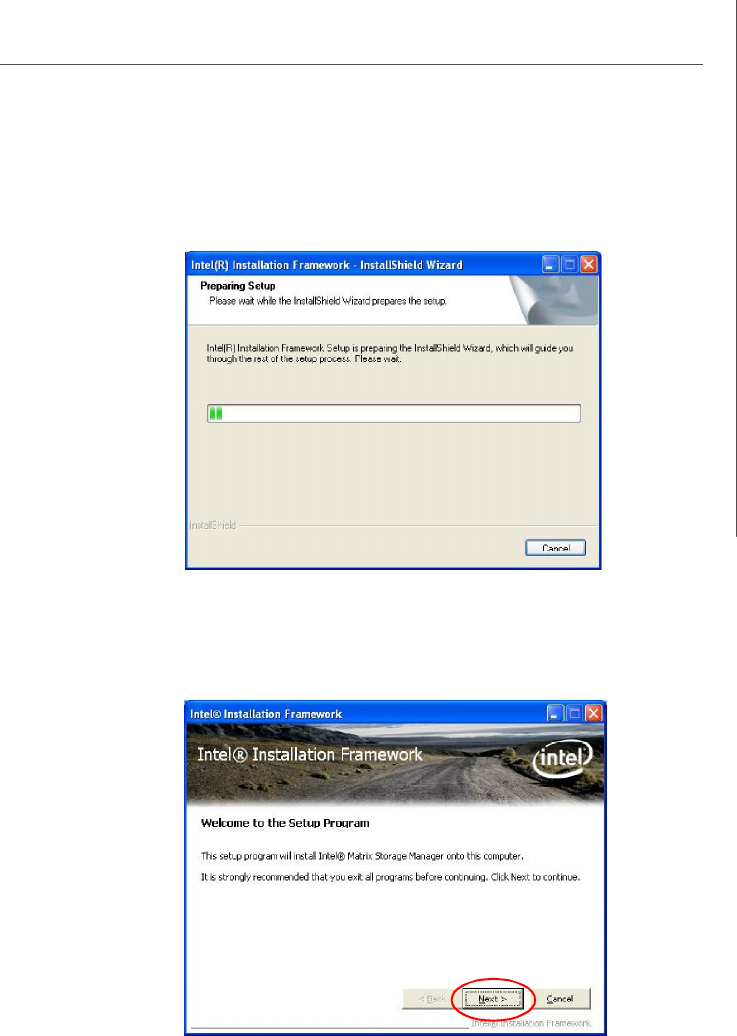
Insert the MSI CD and click on Intel Matrix Storage Manager under the Utility tab
to install the software.
Installing Software
Click on this item
PDF created with pdfFactory Pro trial version www.pdffactory.com
A-16
MS-96C8 Server Board
RAID Migration Instructions
Important
A Create from Existing Disk operation will delete all existing data from the
added disk and the data cannot be recovered. It is critical to backup all
important data on the added disk before proceeding. However, during the
migration process, the data on the source disk is preserved.
The Intel Matrix Storage Console offers the flexibility to upgrade from a single Serial
ATA (SATA) hard drive to RAID configuration when an additional SATA hard drive is
added to the system. This process will create a new RAID volume from an existing
disk. However, several important steps must be followed at the time the system is
first configured in order to take advantage of RAID when upgrading to a second
SATA hard drive:
1.BIOS must be configured for RAID before installing Windows on the single
SATA hard drive. Refer to BIOS section properly setting.
2.Install the Intel Application Accelerator RAID Driver during Windows Setup.
Refer to Installing Software for instructions on installing the driver dur-
ing Windows Setup.
3.Install the Intel Matrix Storage Console after the operating system is installed.
To create a volume from an existing disk, complete the following steps:
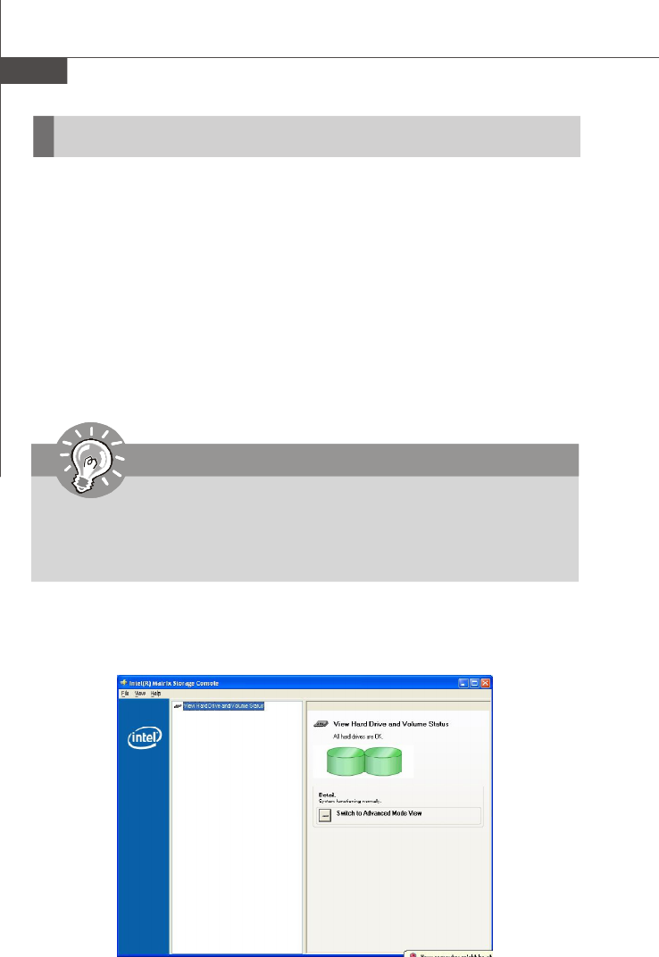
After the Intel Matrix Storage Console has been successfully installed and the sys-
tem has rebooted, click on the Intel Application Accelerator shortcut link (Start --> All
Programs --> Intel Matrix Storage Manager --> Intel Matrix Storage Console)
and the following window will appear:
PDF created with pdfFactory Pro trial version www.pdffactory.com
A-17
Intel ICH10R SATA RAID
Create RAID Volume from Existing Disk
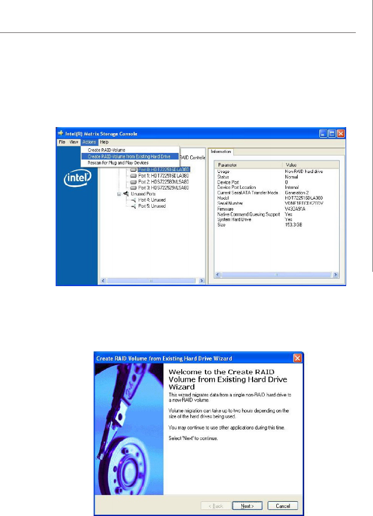
To create a RAID volume from an existing disk, choose Action --> Create RAID
Volume from Existing Hard Drive.
The Create RAID Volume from Existing Hard Drive Wizard pops up to lead you
for the following procedure. Click Next to continue.
PDF created with pdfFactory Pro trial version www.pdffactory.com
A-18
MS-96C8 Server Board
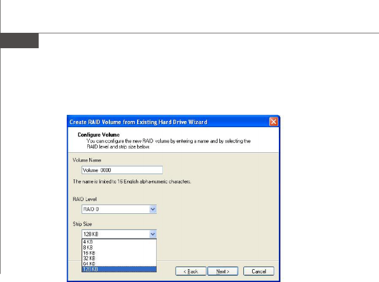
(1) Configure Volume
Here you can configure the new RAID volume by entering the volume name, selecting
the RAID level and strip size.
† RAID Volume Name:
A desired RAID volume name needs to be typed in where the ‘Volume_0000’ text
currently appears above. The RAID volume name has a maximum limit of 16 characters.
The RAID volume name must also be in English alphanumeric ASCII characters.
† RAID Level:
Select the desired RAID level:
RAID 0 (Performance) –A volume optimized for performance will allow you to
access your data more quickly.
RAID 1 (Redundancy) –A volume optimized for data redundancy will provide
you with a realtime duplicate copy of your data. Note:
Only half of the available volume space will be avail-
able for data storage.
RAID 5 (Useful) –RAID 5 can be used on three or more disks, with zero
or more spare-disks. The resulting RAID-5 device size
will be (N-1)*S, where N is the how many drive, S is the
size of the smallest drive in the array. If one of the disks
fail, all data are still intact. It can rebuild the disk from
the parity information. If spare disks are available, re-
construction will begin immediately after the device
failure. If two disks fail simultaneously, all data are lost.
RAID-5 can survive one disk failure, but not two or
more. Both read and write performance usually
increase, but can be hard to predict how much. Reads
are similar to RAID-0 reads, writes can be either rather
PDF created with pdfFactory Pro trial version www.pdffactory.com
A-19
Intel ICH10R SATA RAID
expensive (requiring read-in prior to write, in order to
be able to calculate the correct parity information), or
similar to RAID-1 writes. The write efficiency depends
heavily on the amount of memory in the machine, and
the usage pattern of the array. Heavily scattered writes
are bound to be more expensive.
RAID 10 (Mirrored Stripes) –A RAID 1 array of two RAID 0 arrays.
† Strip Sizes:
Select the desired strip size setting. As indicated, the optimal setting is 128KB. Se-
lecting any other option may result in performance degradation. Even though 128KB
is the recommended setting for most users, you should choose the strip size value
which is best suited to your specific RAID usage model. The most typical strip size
settings are:
4KB: For specialized usage models requiring 4KB strips
8KB: For specialized usage models requiring 8KB strips
16KB: Best for sequential transfers
32KB: Good for sequential transfers
64KB: Good general purpose strip size
128KB: Best performance for most desktops and workstations
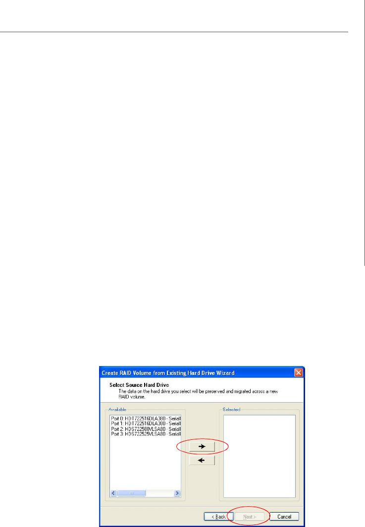
(2) Select the source disk
Then select the source disk that you wish to use and then click “--->” to move it to the
Selected field. Then click Next to continue.
It is very important to note which disk is the source disk (the one containing all of the
information to be migrated) and which one is the target disk. On a RAID Ready
system, this can be determined by making a note during POST of which port the single
disk is attached to.
You can also use the Intel Application Accelerator RAID Edition utility before the
second disk is installed to verify the Port and serial number of the drive that contains
all the data.
PDF created with pdfFactory Pro trial version www.pdffactory.com
A-20
MS-96C8 Server Board
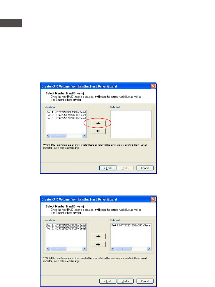
(3) Select Member Hard Drive(s)
Then select the member disk (the target disk) that you wish to use and then click “-
-->” to move it to the Selected field. Then click Next to continue.
Please note that the existing data on the selected hard drive(s) will be deleted
permanently. Do not forget to back up all the important data before continuing.
PDF created with pdfFactory Pro trial version www.pdffactory.com
A-21
Intel ICH10R SATA RAID
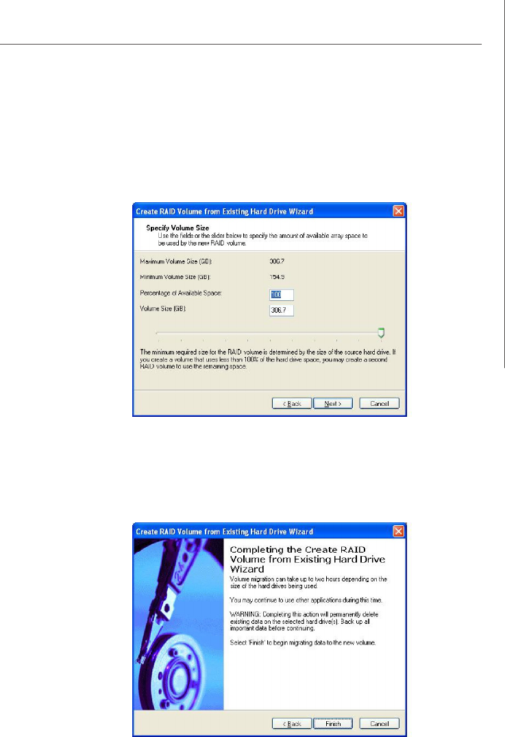
(4) Specify Volume Size
Specify the amount of available array space to be used by the new RAID volume. You
may enter the amount in the space or use the slider to specify. It is recommended you
use 100% of the available space for the optimized usage. For RAID 0 volume, if you
do not specify 100% of the hard drive space, the rest hard drive space will be
worked as RAID 1 volume, which is the new technology called Intel Matrix RAID. Then
click Next to continue.
(5) Start Creating RAID Volume from Existing Hard Drive Wizard
Before you continue the procedure of RAID volume creation from existing hard drive,
read the dialogue box below carefully. Please note that once you click Finish, the
existing data on the selected hard drive(s) will be deleted permanently and this
operation cannot be undone. It is critical that you backup all important data before
selecting Finish to start the migration process.
PDF created with pdfFactory Pro trial version www.pdffactory.com
A-22
MS-96C8 Server Board
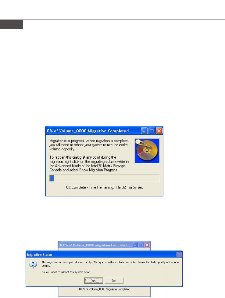
(6) Start Migration
The migration process may take up to two hours to complete depending on the size
of the disks being used and the strip size selected. A dialogue window will appear
stating that the migration process may take considerable time to complete, meanwhile
a popup dialogue at the taskbar will also show the migration status. While you can still
continue using your computer during the migration process, once the migration proc-
ess starts, it cannot be stopped. If the migration process gets interrupted and your
system is rebooted for any reason, it will pick up the migration process where it left
off. You will be provided with an estimated completion time (the remaining time will
depend on your system) once the migration process starts.
The following screen appears if the migration process is completed successfully.
Then you have to reboot your system to use the full capacity of the new volume.
PDF created with pdfFactory Pro trial version www.pdffactory.com
A-23
Intel ICH10R SATA RAID
Recovery Volume Creation
A recovery volume can be created using either Basic mode or Advanced mode in the
Intel Matrix Storage Console.
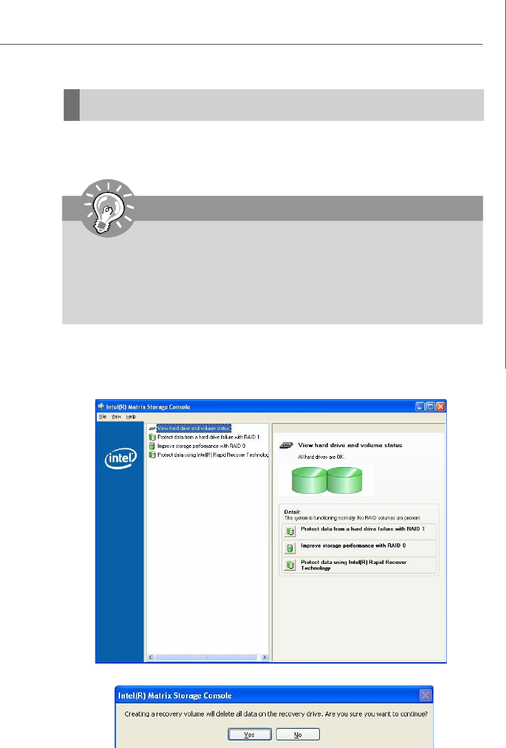
Recovery Volume in Basic Mode Creation
To create a recovery volume in Basic mode, use the following steps:
(1) Open the Intel Matrix Storage Console. (Start --> All Programs --> Intel Matrix
Storage Manager --> Intel Matrix Storage Console)
(2) Select Protect data using IntelR Rapid Recover Technology.
(3) Select Yes to confirm volume creation.
Important
Creating a recovery volume will permanently delete any existing data
on the drive selected as the recovery drive. Back up all important
data before beginning these steps.
This option may or may not be available depending on your system
configuration. If you do not see the option listed, refer to Recovery Volume
Creation in Advanced Mode.
PDF created with pdfFactory Pro trial version www.pdffactory.com
A-24
MS-96C8 Server Board
Recovery Volume in Advanced Mode Creation
To create a recovery volume in Advanced mode, use the following steps:
(1) Open the Intel Matrix Storage Console. (Start --> All Programs --> Intel Matrix
Storage Manager --> Intel Matrix Storage Console)
(2) Select Advanced Mode in the View menu.
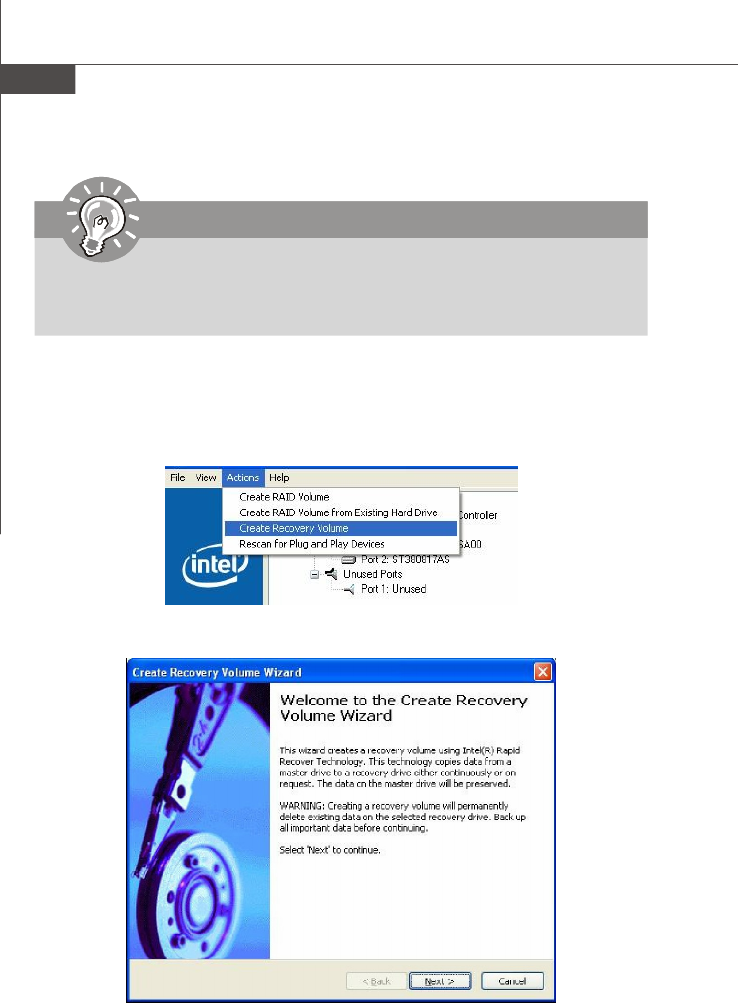
(3) Select Create Recovery Volume in the Actions menu.
(4) Select Next to continue.
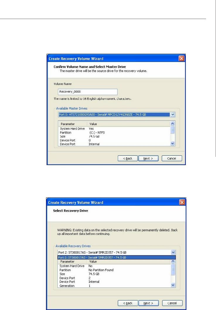
(5) Modify the recovery volume name if you wish.
Important
Creating a recovery volume will permanently delete any existing data
on the drive selected as the recovery drive. Back up all important
data before beginning these steps.
PDF created with pdfFactory Pro trial version www.pdffactory.com
A-27
Intel ICH10R SATA RAID
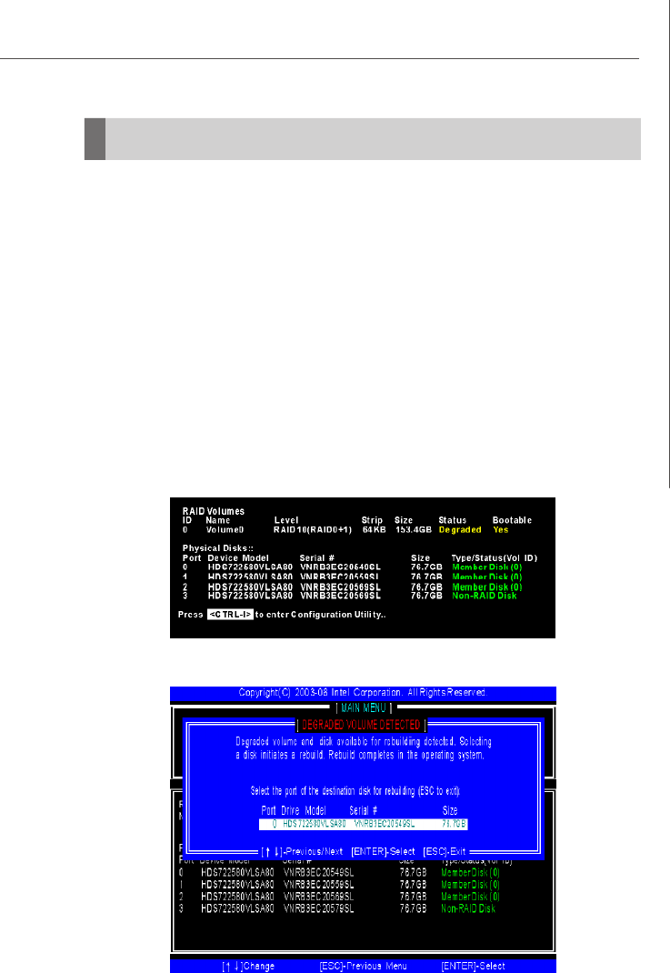
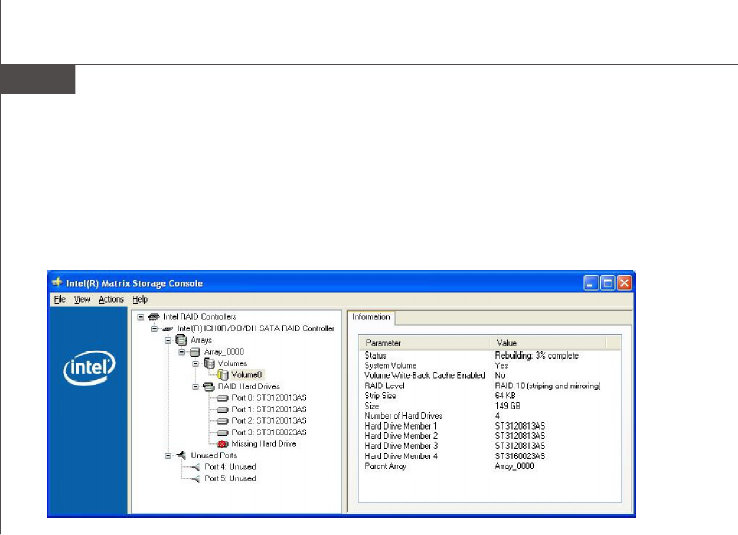
A RAID 1, RAID 5 or RAID 10 volume is reported as degraded when one of its hard
drive members fails or is temporarily disconnected, and data mirroring is lost. As a
result, the system can only utilize the remaining functional hard drive member. To re-
establish data mirroring and restore data redundancy, refer to the procedure below
that corresponds to the current situation.
Missing Hard Drive Member
1. Make sure the system is powered off.
2. Reconnect the hard drive.
3. Reboot the system to Windows; the rebuild will occur automatically.
Failed Hard Drive Member
1. Make sure the system is powered off.
2. Replace the failed hard drive with a new one that is of equal or greater
capacity.
3. Reboot the system to Intel RAID Option ROM by press <Ctrl> and <I> keys
simultaneously during the Power-On Self Test (POST).
Degraded RAID Array
4. Select the port of the destination disk for rebuilding, and then press ENTER.
PDF created with pdfFactory Pro trial version www.pdffactory.com
A-28
MS-96C8 Server Board
5. Exit Intel RAID Option ROM, and then reboot to Windows system.
6. When prompted to rebuild the RAID volume, click 'Yes'.
7. The Intel(R) Storage Utility will be launched. Right-click the new hard drive and
select 'Rebuild to this Disk'. The 'Rebuild Wizard' will be launched which will
guide you through the process of rebuilding to the new hard drive.
PDF created with pdfFactory Pro trial version www.pdffactory.com


B-2
MS-96C8 Server Board
This section provides an overview of the LSI Logic Integrated RAID solution for LSI
Logic SAS controllers, its features, and its benefits.
The LSI Logic Integrated RAID solution provides cost benefits for the server or
workstation market where the extra performance, storage capacity, and/or redun-
dancy of a RAID configuration are required. The two components of Integrated RAID
are: Integrated Mirroring (IM), which provides features of RAID 1 and RAID 1E
(RAID 1 Enhanced). RAID 1E is also called Integrated Mirroring Enhanced
(IME)
Integrated Striping (IS), which provides features of RAID 0
By simplifying the IM and IS configuration options and by providing firmware support
in its host adapters, LSI Logic can offer the Integrated RAID solution at a lower cost
than a hardware RAID implementation.
Fusion-MPT™ firmware supports IM and IS volumes. You can configure IM and IS
volumes together on the same LSI Logic SAS controller.
Integrated RAID Benefits and Features
Low cost RAID volume creation meets the needs of most internal RAID instal-
lations
Easy to use - installation and configuration are not complex
System can boot from an IM, IME, or IS volume
No special OS-specific software required
High reliability and data integrity
– Non-volatile write journaling
– Physical disks not visible to OS or to application software
Low host CPU and PCI bus utilization
Fusion-MPT architecture provides processing power
– Shared memory architecture minimizes external memory requests
– Functionality is contained in device hardware and firmware
1. Introduction to Integrated RAID
PDF created with pdfFactory Pro trial version www.pdffactory.com

B-3
LSI SAS RAID
2. Integrated Mirroring Overview
This section provides an overview of the LSI Logic Integrated Mirroring (IM) feature.
2.1 Introduction
As a result of the shift towards Network Attached Storage (NAS), ISPs need a cost
effective, fault-tolerant solution to protect the operating systems on small form factor,
high-density, rack-mountable servers. The LSI Logic Integrated Mirroring (IM) fea-
ture—which includes Integrated Mirroring Enhanced (IME)—provide data protection
for the system boot volume to safeguard critical information such as the operating
system on servers and high performance workstations. The Integrated Mirroring
feature gives customers a robust, high-performance, fault-tolerant solution to their
storage needs, at a lower cost than a dedicated RAID controller.
The Integrated Mirroring feature supports simultaneous mirrored volumes with two
disks (IM) or three to eight disks (IME), to provide fault-tolerant protection for critical
data. (If a hot spare disk is used, the maximum volume size is seven mirrored disks,
plus the hot spare disk.) Up to two IM volumes are supported per SAS controller, with
up to ten drives total per controller.
vNote: Ten disk drives is the theoretical upper limit, although the SAS controller
itself may support fewer drives.
If a disk in an Integrated Mirroring volume fails, the hot swap capability allows the
volume to be easily restored by simply swapping disks. The firmware then automati-
cally re-mirrors the swapped disk. Additionally, each SAS controller can have one
global hot spare disk available to automatically replace a failed disk in the one or two
IM or IME volumes configured on the controller. The hot spare makes the Integrated
Mirroring volume even more fault-tolerant.
vNote: You can configure an Integrated Mirroring volume and an Integrated Striping
volume on the same LSI Logic SAS controller.
The IM feature uses the same device drivers as the standard LSI Logic Fusion-MPT
based controllers, providing seamless and transparent fault tolerance. This elimi-
nates the need for complex backup software or expensive RAID hardware. The IM
feature operates independently from the operating system, in order to conserve
system resources. The BIOSbased configuration utility makes it easy to configure IM
and IME volumes.
The Integrated Mirroring feature is currently available as an optional component of
the Fusion-MPT architecture on LSI Logic controller products.
PDF created with pdfFactory Pro trial version www.pdffactory.com

B-4
MS-96C8 Server Board
2.2 IM Features
LSI Logic Integrated Mirroring and Integrated Mirroring Enhanced support the follow-
ing features:
Configurations of one or two IM or IME volumes on the same LSI Logic SAS
controller. Each volume can consist of two mirrored disks (IM) or three to eight
mirrored disks (IME).
(Optional) One global hot spare disk per controller. If a global hot spare disk is
defined, the upper limit for an IME volume is seven mirrored disks.
Mirrored volumes run in optimal mode or in degraded mode (if one mirrored disk
fails)
Hot swap capability
Presents a single virtual drive to the OS for each IM/IME volume
Supports both SAS and SATA disks, although the two types of disks cannot be
combined on the same LSI Logic SAS controller
Fusion-MPT architecture
Easy-to-use BIOS-based configuration utility (and DOS-based configuration
utility for manufacturing use only)
Error notification: OS-specific event log updated by drivers and errors dis-
played inside the Fusion-MPT BIOS
SES status LED support for Integrated Mirroring disks
Write journaling, which allows automatic synchronization of potentially incon-
sistent data after unexpected power-down situations
Metadata used to store volume configuration on mirrored disks
Automatic background resynchronization while host I/Os continue
Background media verification ensures that data on the IM volume is acces-
sible
PDF created with pdfFactory Pro trial version www.pdffactory.com
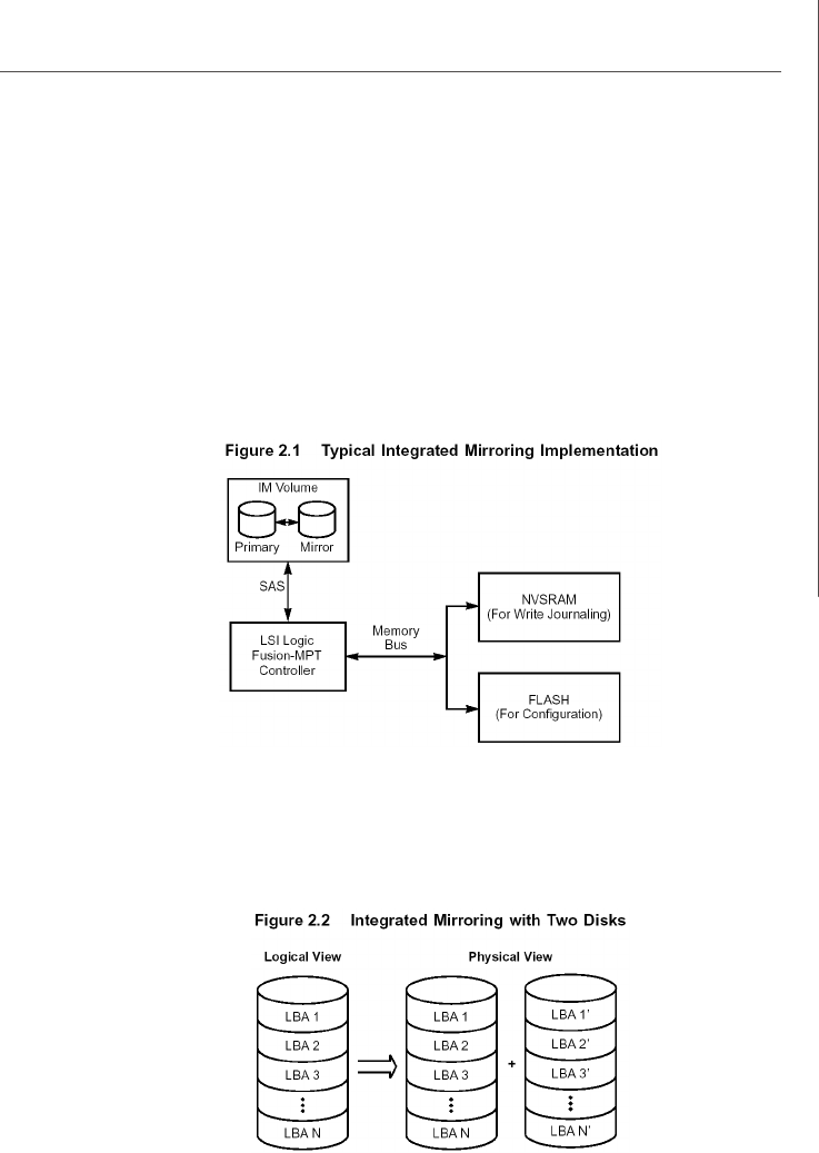
B-5
LSI SAS RAID
2.3 IM/IME Description
The LSI Logic Integrated Mirroring (IM) feature supports one or two mirrored volumes
on each LSI Logic SAS controller (or one mirrored volume and one Integrated Striping
volume). Typically, one of these volumes is the boot volume, as shown in Figure 2.1.
This is accomplished through the firmware of the LSI Logic SAS controller that
supports the standard Fusion-MPT interface. The runtime mirroring of the boot disk is
transparent to the BIOS, drivers, and operating system.
Host-based status software monitors the state of the mirrored disks and reports any
error conditions. In Figure 2.1 the system is configured with a second disk as a mirror
of the first (primary) disk.
The advantage of Integrated Mirroring (RAID 1), is that there is always a mirrored
copy of the data. The disadvantage is that writes take longer because data must be
written twice. On the other hand, performance is actually improved during reads.
Figure 2.2 shows the logical view and physical view of an Integrated Mirroring
configuration with two disks in the mirrored volume.
PDF created with pdfFactory Pro trial version www.pdffactory.com
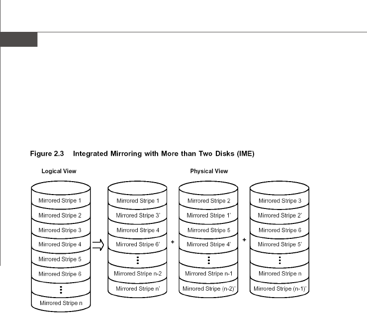
B-6
MS-96C8 Server Board
An IME volume can be configured with up to eight mirrored disks, or seven mirrored
disks and a global hot spare. Figure 2.3 shows the logical view and physical view of
an Integrated Mirroring Enhanced (IME) volume with three mirrored disks. Each mir-
rored stripe is written to a disk and mirrored to an adjacent disk. This type of configu-
ration is also called RAID 1E.
LSI Logic provides the BIOS-based configuration utility to enable the user to create IM
and IME volumes during initial setup and to reconfigure them in response to hardware
failures or changes in the environment.
PDF created with pdfFactory Pro trial version www.pdffactory.com

B-7
LSI SAS RAID
2.4 Integrated Mirroring Firmware
This section describes features of the LSI Logic Integrated Mirroring (IM) firmware,
which supports up to two IM volumes per LSI Logic SAS controller.
2.4.1 Host Interface
The IM host interface uses the Message Passing Interface, as described in the
Fusion-MPT Message Passing Interface Specification. Through the Fusion-
MPT interface, the host OS has access to the IM volume as well as the physical
disks.
2.4.2 Resynchronization with Concurrent Host I/O Operation
The IM firmware allows Host I/Os to continue on the IM/IME volume while the
volume is being re-synchronized in the background. Resynchronization is at-
tempted after a hot spare is activated due to a physical device failure, or after
a hot swap has occurred to a physical disk in the IM or IME volume.
2.4.3 Metadata Support
The firmware supports metadata, which describes the IM/IME logical drive con-
figuration stored on each member disk. When the firmware is initialized, each
member disk is queried to read the stored metadata in order to verify the
configuration. The usable disk space for each member disk is adjusted down to
leave room for this data.
2.4.4 Hot Swapping
The IM firmware supports hot swapping. The hot-swapped disk is automatically
resynchronized in the background, without any host or user intervention. The
firmware detects hot swap removal and disk insertion.
Following a hot swap event, the firmware readies the new physical disk by
spinning it up and verifying that it has enough capacity for the mirrored volume.
The IM firmware resynchronizes all hot-swapped disks that have been removed,
even if the same disk is re-inserted. In a two-disk mirrored volume, the IM
firmware marks the hot-swapped disk as the secondary disk and marks the
other mirrored disk as the primary disk. The firmware resynchronizes all data
from the primary disk onto the new secondary disk.
2.4.5 SMART Support
The IM firmware enables Mode 6 SMART on the member disks in the mirrored
volume. Mode 6 SMART requires each physical disk to be polled at regular
intervals. If a SMART ASC/ASCQ code is detected on a physical disk in the
volume, the firmware processes the SMART data, and the last received SMART
ASC/ASCQ is stored in non-volatile memory. The IM/IME volume does not sup-
port SMART directly, since it is just a logical representation of the physical disks
in the volume.
2.4.6 Hot Spare Disk
One disk can be configured as a global hot spare disk, which protects data on
the one or two volumes configured on the controller. If the IM firmware fails one
of the mirrored disks, the firmware automatically replaces it with the hot spare
PDF created with pdfFactory Pro trial version www.pdffactory.com

B-8
MS-96C8 Server Board
disk. The IM firmware then resynchronizes the mirrored data. The IM firmware
is automatically notified when the failed disk has been replaced, and the firm-
ware then designates that disk as the new hot spare.
2.4.7 Media Verification
The IM firmware supports a background media verification feature that runs at
regular intervals when the IM/IME volume is in optimal mode. If the verification
command fails for any reason, the other disk’s data for this segment is read and
written to the failing disk in an attempt to refresh the data. The current Media
Verification Logical Block Address is written to non-volatile memory occasion-
ally to allow Media Verification to continue approximately where it left off prior
to a power-cycle.
2.4.8 Disk Write Caching
The IM firmware disables disk write caching by default. This is done to increase
data integrity, so that the disk write log stored in NVSRAM is always valid. If
disk write caching were enabled (not recommended), the disk write log could
be invalid.
2.4.9 NVSRAM Usage
For the LSISAS1064/1064E and LSISAS1068/1068E controllers, the IM firm-
ware requires at least a 32K NVSRAM in order to perform write journaling.
Write journaling is used to verify that the mirrored disks in the IM/IME volume are
synchronized with each other.
2.5 Fusion-MPT Support
The BIOS uses the LSI Logic Fusion-MPT interface to communicate to the SAS con-
troller and firmware to enable Integrated Mirroring. This includes reading the Fusion-
MPT configuration to gain access to the parameters that are used to define behavior
between the SAS controller and the devices connected to it. The Fusion-MPT drivers
for all supported operating systems implement the Fusion-MPT interface to communi-
cate with the controller and firmware.
PDF created with pdfFactory Pro trial version www.pdffactory.com

B-9
LSI SAS RAID
3. Creating Integrated Mirroring Volumes
This section describes how to create Integrated Mirroring (IM) and Integrated Mirror-
ing Enhanced (IME) volumes using the LSI Logic SAS BIOS Configuration Utility (SAS
BIOS CU).
3.1 IM Configuration Overview
You can use the SAS BIOS CU to create one or two IM or IME volumes on each LSI
Logic SAS controller, with an optional global hot spare disk. All disks in an IM or IME
volume must be connected to the same LSI Logic SAS controller.
Although you can use disks of different size in IM and IME volumes, the smallest disk
determines the “logical” size of each disk in the volume. In other words, the excess
space of the larger member disk is not used.
Refer to Section 2.2, “IM Features,” for more information about Integrated Mirroring
volumes.
3.2 Creating IM and IME Volumes
The SAS BIOS CU is part of the Fusion-MPT BIOS. When the BIOS loads during boot
and you see the message about the LSI Logic Configuration Utility, press Ctrl-C to
start the CU. After you do this, the message changes to:
Please wait, invoking SAS Configuration Utility...
After a brief pause, the main menu of the SAS BIOS CU appears. On some systems,
however, the following message appears next:
LSI Logic Configuration Utility will load following initialization!
In this case, the SAS BIOS CU will load after the system has completed its power-on
self test.
You can configure one or two IM or IME volumes per Fusion-MPT controller. You can
also combine IM, IME, and Integrated Striping volumes on the same controller, up to a
maximum of 10 physical disk drives.
The following guidelines also apply when creating an IM or IME volume:
All physical disks in the volumes must be either SATA (with extended command
set support) or SAS (with SMART support). SAS and SATA disks cannot be
combined in the same volume.
Disks must have 512-byte blocks and must not have removable media.
An IM volume must have two drives, plus an optional global hot spare. An IME
volume. An IME volume can have three to eight drives, or three to seven drives
if you also create a global hot spare.
vNote: If a disk in an IM or IME volume fails, it is rebuilt on the global hot spare if one
PDF created with pdfFactory Pro trial version www.pdffactory.com
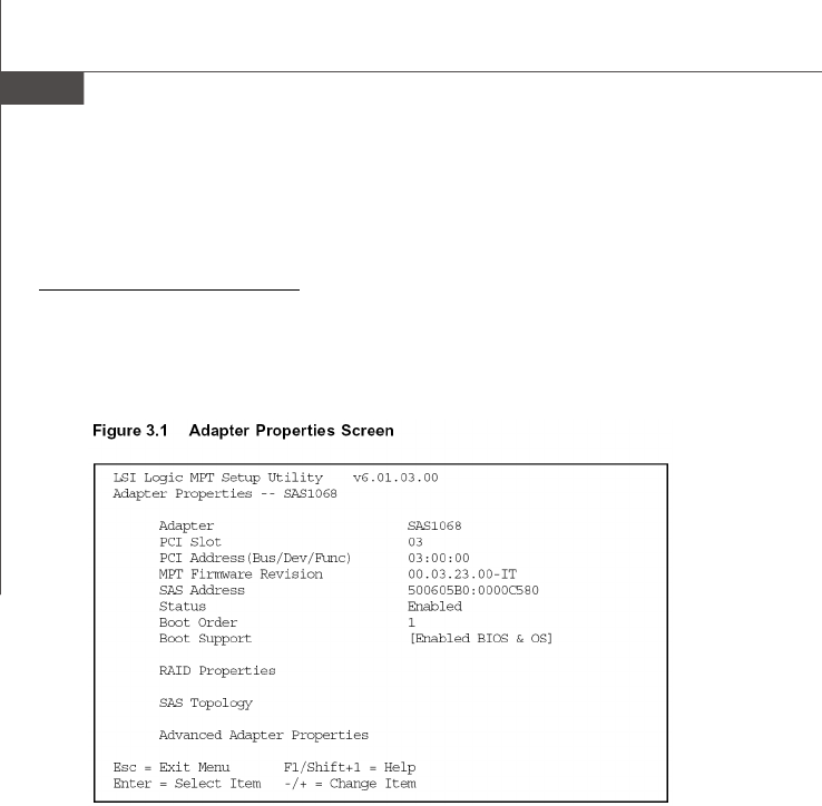
B-10
MS-96C8 Server Board
is available. So adding a global hot spare greatly increases the level of data
protection. (One global hot spare is allowed for the one or two volumes config
ured on a controller.)
3.2.1 Creating an IM Volume
Follow these steps to create an IM volume with the SAS BIOS CU:
1. On the Adapter List screen, use the arrow keys to select an LSI Logic SAS
adapter.
2. Press Enter to go to the Adapter Properties screen, shown in Figure 3.1.
3. On the Adapter Properties screen, use the arrow keys to select RAID Proper-
ties on the screen and press Enter.
4. When you are prompted to select a volume type, select Create IM Volume.
The Create New Array screen shows a list of disks that can be added to a
volume.
5. Move the cursor to the “RAID Disk” column and select a disk. To add the disk to
the volume, change the “No” to “Yes” by pressing the + key, . key, or space
bar. When the first disk is added, the SAS BIOS CU prompts you to either keep
existing data or overwrite existing data.
6. Press M to keep the existing data on the first disk or press D to overwrite it. If
you keep the existing data, this is called a migration. The first disk will be
mirrored onto the second disk, so the data you want to keep must be on the
first disk added to the volume. Any data on the second disk is overwritten. As
disks are added the Array Size field changes to reflect the size of the new
volume.
7. (optional) Add a global hot spare by moving the cursor to the hot spare column
and pressing the + key, . key, or space bar.
PDF created with pdfFactory Pro trial version www.pdffactory.com
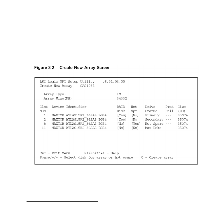
B-11
LSI SAS RAID
Figure 3.2 shows an IM volume configured with a global hot spare disk.
8. When the volume has been fully configured, press C and then select Save
changes then exit this menu to commit the changes. The SAS BIOS CU
pauses while the array is being created.
3.2.2 Creating an IME Volume
Follow these steps to create an IME volume with the SAS BIOS CU:
1. On the Adapter List screen, use the arrow keys to select an LSI Logic SAS
adapter.
2. Press Enter to go to the Adapter Properties screen, shown in Figure 3.1.
3. On the Adapter Properties screen, use the arrow keys to select RAID Proper-
ties on the screen and press Enter.
4. When you are prompted to select a volume type, select Create IME Volume.
The Create New Array screen shows a list of disks that can be added to a
volume.
5. Move the cursor to the “RAID Disk” column and select a disk. To add the disk to
the volume, change the “No” to “Yes” by pressing the + key, . key, or space
bar.
6. Repeat this step to select a total of three to eight disks for the volume (or three
to seven disks if you will create a global hot spare). All existing data on all the
disks you select will be overwritten. As you add disks, the Array Size field
changes to reflect the size of the new volume.
7. (optional) Add a global hot spare to the volume by moving the cursor to the hot
spare column and pressing the + key, . key, or space bar.
8. When the volume has been fully configured, press C and then select Save
changes then exit this menu to commit the changes. The SAS BIOS CU
pauses while the array is being created.
PDF created with pdfFactory Pro trial version www.pdffactory.com

B-12
MS-96C8 Server Board
3.3 Creating a Second IM or IME Volume
The LSI Logic SAS controllers allow you to configure two IM or IME volumes. If one
volume is already configured, and if there are available disk drives, there are two
ways to add a second volume.
The first is as follows:
1. In the configuration utility, select an adapter from the Adapter List. Select the
RAID Properties option. This will display the current volume.
2. Press C to create a new volume.
3. Continue with step 4 of the IM or IME creation procedure in the previous section
to create a second volume.
The other way in which to add a second volume is as follows:
1. On the Adapter List screen, use the arrow keys to select an LSI Logic SAS
adapter.
2. Press Enter to go to the Adapter Properties screen, shown in Figure 3.1.
3. On the Adapter Properties screen, use the arrow keys to select RAID Proper-
ties and press Enter.
4. Continue with step 4 of the IM or IME creation procedure in the previous section
to create a second volume.
PDF created with pdfFactory Pro trial version www.pdffactory.com
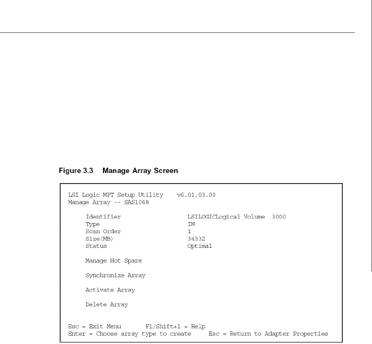
B-13
LSI SAS RAID
3.4 Managing Hot Spares
You can create one global hot spare disk to protect the one or two IM/IME volumes
defined on a SAS controller. Usually, you create the global hot spare at the same time
you create the IM/IME volume. Follow these steps to add a global hot spare disk later
for the existing IM/IME volumes on the controller:
1. On the View Array screen, select Manage Array.
2. Select Manage Hot Spare on the Manage Array screen, shown in Figure 3.3.
3. Select a disk from the list by pressing the + key, . key, or space bar.
4. After you select the global hot spare disk, press C. An error message appears
if the selected disk is not at least as large as the smallest disk used in the IM/
IME volume(s). The global hot spare disk must have 512-byte blocks, it cannot
have removable media, and the disk type must be either SATA with extended
command set support or SAS with SMART support. If SATA disks are used for
the IM/IME volume(s), the hot spare disk must also be a SATA disk. If SAS disks
are used, the hot spare disk must also be a SAS disk. An error message
appears if the selected disk is not the same type as the disks used in the IM/IME
volumes.
5. Select Save changes then exit this menu to commit the changes. The
configuration utility will pause while the global hot spare is being added.
Follow these steps to delete a global hot spare:
1. Select Manage Hot Spare on the Manage Array screen.
2. Select Delete Hot Spare and then press C.
3. Select Save changes then exit this menu to commit the changes. The
configuration utility will pause while the global hot spare is being removed.
PDF created with pdfFactory Pro trial version www.pdffactory.com

B-14
MS-96C8 Server Board
3.5 Other Configuration Tasks
This section explains how to do other tasks related to configuring and maintaining IM
and IME volumes.
3.5.1 Viewing Volume Properties
Follow these steps to view the properties of volumes:
1. In the SAS BIOS CU, select an adapter from the Adapter List. Select the RAID
Properties option. The properties of the current volume are displayed. If a
global hot spare is defined, it is also listed.
v Note: If you create one volume using SAS disks, another volume using SATA
disks, and a global hot spare disk, the hot spare disk will only appear when
you view the volume that has the same type of disks as the hot spare disk.
2. If two volumes are configured, press Alt+N to view the other array.
3. To manage the current array, select the Manage Array item and press Enter.
3.5.2 Synchronizing an Array
The Synchronize Array command forces the firmware to resynchronize the data on
the mirrored disks is the array. It is seldom necessary to use this command, because
the firmware automatically keeps the mirrored data synchronized during normal sys-
tem operation. When you use this command, one disk of the array is placed in the
Degraded state until the data on the mirrored disks has been resynchronized.
Follow these steps to force the synchronization of a selected array:
1. Select Synchronize Array on the Manage Array screen.
2. Press Y to start the synchronization, or N to cancel it.
3.5.3 Activating an Array
An array can become inactive if, for example, it is removed from one controller or
computer and moved to another one. The “Activate Array” option allows you to
reactivate an inactive array that has been added to a system. This option is only
available when the selected array is currently inactive.
Follow these steps to activate a selected array
1. Select Activate Array on the Manage Array screen.
2. Press Y to proceed with the activation, or press N to abandon it. After a pause,
the array will become active.
v Note: If there is a global hot spare disk on the controller to which you have
moved the array, the firmware checks when you activate the array to deter-
mine if the hot spare is compatible with the new array. An error message
appears if the disks in the activated array are larger than the hot spare disk or
if the disks in the activated array are not the same type as the hot spare disk
(SATA versus SAS).
3.5.4 Deleting an Array
v CAUTION: Before deleting an array, be sure to back up all data on the array that
you want to keep.
PDF created with pdfFactory Pro trial version www.pdffactory.com

B-15
LSI SAS RAID
Follow these steps to delete a selected array:
1. Select Delete Array on the Manage Array screen.
2. Press Y to delete the array.
After a pause, the firmware deletes the array. If there is another remaining
array and a global hot spare disk, the firmware checks the hot spare disk to
determine if it is compatible with the remaining array. If the hot spare disk is not
compatible (too small or wrong disk type) the firmware deletes it also.
v Note: After a volume has been deleted, it cannot be recovered. When a RAID
1 volume is deleted, the data is preserved on the primary disk. The master boot
records (MBR) of other disks in the array are deleted. For other RAID types,
the master boot records of all disks are deleted.
3.5.5 Locating a Disk Drive, or Multiple Disk Drives in a Volume
You can use the SAS BIOS CU to locate and identify a specific physical disk drive by
flashing the drive’s LED. You can also use the SAS BIOS CU to flash the LEDs of all
the disk drives in a RAID volume. There are several ways to do this:
When you are creating an IM or IME volume, and a disk drive is set to Yes as
part of the volume, the LED on the disk drive is flashing. The LED is turned off
when you have finished creating the volume.
You can locate individual disk drives from the SAS Topology screen. To do this,
move the cursor to the name of the disk in the Device Identifier column and
press Enter. The LED on the disk flashes until the next key is pressed.
You can locate all the disk drives in a volume by selecting the volume on the
RAID Properties screen. The LEDs flash on all disk drives in the volume.
v Note: The LEDs on the disk drives will flash as described above if the firmware
is correctly configured and the drives or the disk enclosure supports disk
location.
3.5.6 Selecting a Boot Disk
You can select a boot disk in the SAS Topology screen. This disk is then moved to
scan ID 0 on the next boot, and remains at this position. This makes it easier to set
BIOS boot device options and to keep the boot device constant during device addi-
tions and removals. There can be only one boot disk.
Follow these steps to select a boot disk:
1. In the SAS BIOS CU, select an adapter from the Adapter List.
2. Select the SAS Topology option.
The current topology is displayed. If the selection of a boot device is supported,
the bottom of the screen lists the Alt+B option. This is the key for toggling the
boot device. If a device is currently configured as the boot device, the Device
Info column on the SAS Topology screen will show the word “Boot.”
3. To select a boot disk, move the cursor to the disk and press Alt+B.
4. To remove the boot designator, move the cursor down to the current boot disk
and press Alt+B. This controller will no longer have a disk designated as boot.
5. To change the boot disk, move the cursor to the new boot disk and press
Alt+B. The boot designator will move to this disk.
v Note: The firmware must be configured correctly in order for the Alt+B feature
to work.
PDF created with pdfFactory Pro trial version www.pdffactory.com

B-16
MS-96C8 Server Board
4. Integrated Striping Overview
This section provides an overview of the LSI Logic Integrated Striping (IS) feature.
4.1 Introduction
The LSI Logic Integrated Striping (IS) feature is useful for applications that require the
faster performance and increased storage capacity of striping. The low-cost IS
feature has many of the advantages of a more expensive RAID striping solution. A
single IS logical drive may be configured as the boot disk or as a data disk.
The IS feature is implemented with controller firmware that supports the Fusion-MPT
Interface. IS provides better performance and more capacity than individual disks,
without burdening the host CPU. The firmware splits host I/Os over multiple disks and
presents the disks as a single logical drive. In general, striping is transparent to the
BIOS, the drivers, and the operating system.
The SAS BIOS CU is used to configure IS volumes, which can consist of two to eight
disks.
v Note: Integrated Mirroring and Integrated Striping volumes can be configured
on the same LSI logic SAS controller.
4.2 IS Features
Integrated Striping supports the following features:
Support for volumes with two to eight drives
Support for two IS volumes, with up to 10 drives total, on a controller. An IS
volume can also be combined with an IM or IME volume.
v Note: Currently available LSI Logic SAS controllers support a maximum of eight
drives. All drives in a volume must be connected to the same SAS controller.
Presents a single virtual drive to the OS for each configured volume
Support for both SAS and SATA drives, although the two types of drives
cannot be combined in one volume
Fusion-MPT architecture
Easy-to-use SAS BIOS configuration utility
Error notification
Use of metadata to store volume configuration on disks
OS-specific event log
Error display inside the Fusion-MPT BIOS
SES status LED support for drives used in IS volumes
PDF created with pdfFactory Pro trial version www.pdffactory.com
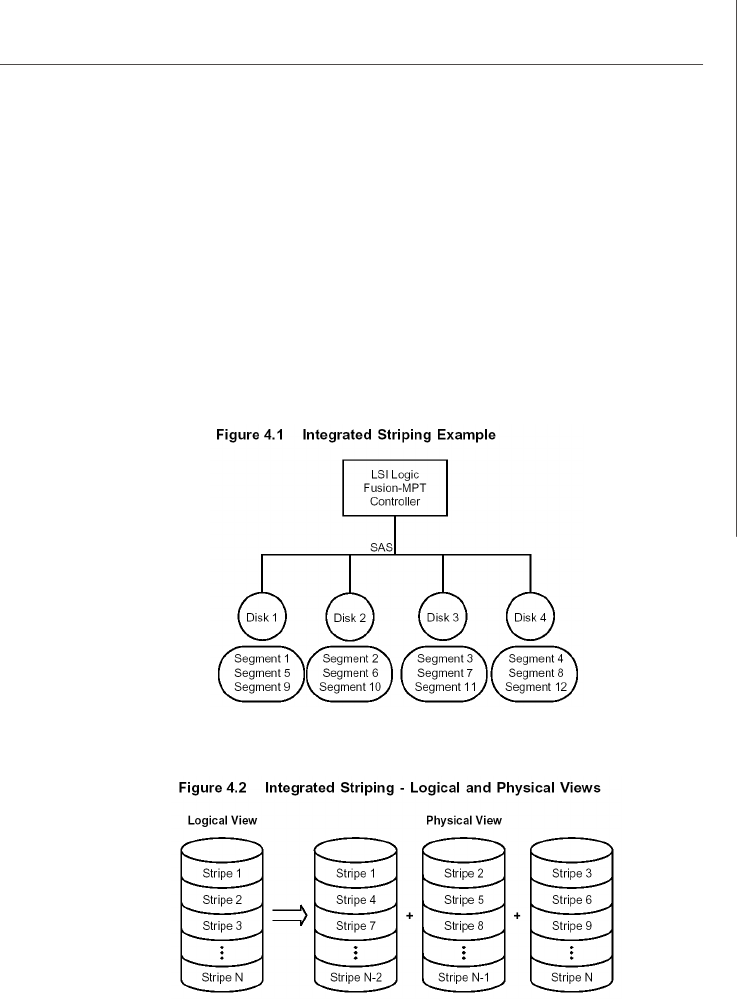
B-17
LSI SAS RAID
4.3 IS Description
The IS feature writes data across multiple disks instead of onto one disk.
This is accomplished by partitioning each disk’s storage space into 64 Kbyte stripes.
These stripes are interleaved round-robin, so that the combined storage space is
composed alternately of stripes from each disk.
For example, as shown in Figure 4.1, segment 1 is written to disk 1, segment 2 is
written to disk 2, segment 3 is written to disk 3, and so on. When the system reaches
the end of the disk list, it continues writing data at the next available segment of disk
1.
Figure 4.2 shows a logical view and a physical view of Integrated Striping configuration.
The primary advantage of IS is speed, because it transfers data to or from multiple
disks at once. However, there is no data redundancy; therefore, if one disk fails, that
data is lost.
PDF created with pdfFactory Pro trial version www.pdffactory.com

B-18
MS-96C8 Server Board
4.4 Integrated Striping Firmware
This section describes features of the LSI Logic Integrated Striping (IS) firmware.
4.4.1 Host Interface
The IS host interface uses the Message Passing Interface, as described in the
Fusion-MPT Message Passing Interface Specification, including Integrated
Striping. Through the Fusion-MPT interface, the host operating system has
access to the logical IS drive as well as the physical disks.
4.4.2 Metadata Support
The firmware supports metadata, which describes the IS logical drive configu-
ration stored on each member disk. When the firmware is initialized, each
member disk is queried to read the stored metadata to verify the configuration.
The usable disk space for each IS member disk is adjusted down to leave room
for this data.
4.4.3 SMART Support
The IS firmware enables Mode 6 SMART on the IS member disks. Mode 6
SMART requires each physical disk to be polled at regular intervals. If a SMART
ASC/ASCQ code is detected on a physical IS disk, the firmware processes the
SMART data, and the last received SMART ASC/ASCQ is stored in non-volatile
memory. The IS volume does not support SMART directly, since it is just a logical
representation of the physical disks in the volume.
4.4.4 Disk Write Caching
Disk write caching is disabled by default on all IS volumes.
4.5 Fusion-MPT Support
The BIOS uses the LSI Logic Fusion-MPT interface to communicate to the SAS con-
troller and firmware to enable Integrated Striping. This includes reading the Fusion-
MPT configuration to gain access to the parameters that are used to define behavior
between the SAS controller and the devices connected to it. The Fusion-MPT drivers
for all supported operating systems implement the Fusion-MPT interface to communi-
cate with the controller and firmware.
PDF created with pdfFactory Pro trial version www.pdffactory.com

B-19
LSI SAS RAID
5. Creating Integrated Striping Volumes
This section describes how to create Integrated Striping (IS) volumes using the LSI
Logic SAS BIOS Configuration Utility (SAS BIOS CU).
5.1 IS Configuration Overview
You can use the SAS BIOS CU to create multiple IS volumes, with up to 10 drives total
on an LSI Logic SAS controller. Each volume can have from 2 to 8 drives. Disks in an
IS volume must be connected to the same LSI Logic SAS controller, and the controller
must be in the BIOS boot order.
Although you can use disks of different size in IS volumes, the smallest disk deter-
mines the “logical” size of each disk in the volume. In other words, the excess space
of the larger member disk is not used. Usable disk space for each disk in an IS volume
is adjusted down to leave room for metadata. Usable disk space may be further
reduced to maximize the ability to interchange disks in the same size classification.
The supported stripe size is 64 Kbytes.
Refer to Section 4.2, “IS Features,” for more information about Integrated Striping
volumes.
5.2 Creating IS Volumes
The SAS BIOS CU is part of the Fusion-MPT BIOS. When the BIOS loads during boot
and you see the message about the Setup Utility, press Ctrl-C to start it. After you do
this, the message changes to:
Please wait, invoking SAS Configuration Utility...
After a brief pause, the main menu of the SAS BIOS CU appears. On some systems,
however, the following message appears next:
LSI Logic Configuration Utility will load following initialization!
In this case, the SAS BIOS CU will load after the system has completed its power-on
self test.
Follow the steps below to configure an Integrated Striping (IS) volume with the SAS
BIOS CU. The procedure assumes that the required controller(s) and disks are al-
ready installed in the computer system. You can configure both IM and IS volumes on
the same SAS controller.
1. On the Adapter List screen of the SAS BIOS CU, use the arrow keys to select
a SAS adapter.
PDF created with pdfFactory Pro trial version www.pdffactory.com
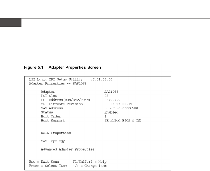
B-20
MS-96C8 Server Board
2. Press Enter to go to the Adapter Properties screen, shown in Figure 5.1.
3. On the Adapter Properties screen, use the arrow keys to select RAID Proper-
ties on the screen and press Enter.
4. When you are prompted to select a volume type, select Create IS Volume.
The Create New Array screen shows a list of disks that can be added to a
volume.
5. Move the cursor to the “RAID Disk” column. To add a disk to the volume, change
the “No” to “Yes” by pressing the + key, . key, or space bar. As disks are
added, the Array Size field changes to reflect the size of the new volume.
There are several limitations when creating an IS (RAID 0) volume:
– All disks must be either SATA (with extended command set support) or SAS
(with SMART support).
– Disks must have 512-byte blocks and must not have removable media.
– There must be at least 2 and no more than 8 drives in a valid IS volume. Hot
spare drives are not allowed.
PDF created with pdfFactory Pro trial version www.pdffactory.com
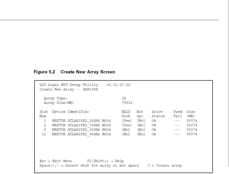
B-21
LSI SAS RAID
Figure 5.2 shows an IS volume configured with two drives.
6. When the volume has been fully configured, press C and then select Save
changes then exit this menu to commit the changes. The configuration
utility will pause while the array is being created.
v Note: Integrated Striping does not provide any data protection in the event of
disk failure. It is primarily used to increase speed.
5.3 Creating a Second IS Volume
The LSI Logic SAS controllers allow you to configure two IS volumes, or an IS volume
and an IM or IME volume. If one volume is already configured, and if there are
available disk drives, there are two ways to add a second volume.
The first is as follows:
1. In the configuration utility, select an adapter from the Adapter List. Select the
RAID Properties option. This will display the current volume.
2. Press C to create a new volume.
3. Continue with step 4 of Section 5.2, “Creating IS Volumes,” to create a second
IS volume.
The other way in which to add a second volume is as follows:
1. On the Adapter List screen, use the arrow keys to select an LSI Logic SAS
adapter.
2. Press Enter to go to the Adapter Properties screen, shown in Figure 5.1.
PDF created with pdfFactory Pro trial version www.pdffactory.com

B-22
MS-96C8 Server Board
3. On the Adapter Properties screen, use the arrow keys to select RAID Proper-
ties and press Enter.
4. Continue with step 4 of the IS creation procedure in the previous section to
create a second volume.
5.4 Other Configuration Tasks
This section explains how to do other tasks related to configuring and maintaining IS
volumes.
5.4.1 Viewing IS Volume Properties
Follow these steps to view the properties of IS volumes:
1. In the configuration utility, select an adapter from the Adapter List. Select the
RAID Properties option. The properties of the current volume are displayed.
2. If more than one volume is configured, press Alt+N to view the next array.
3. To manage the current array, press Enter when the Manage Array item is
selected.
5.4.2 Activating an Array
An array can become inactive if, for example, it is removed from one controller or
computer and moved to another one. The “Activate Array” option allows you to
reactivate an inactive array that has been added to a system. This option is only
available when the selected array is currently inactive.
Follow these steps to activate a selected array.
1. Select Activate Array on the Manage Array screen.
2. Press Y to proceed with the activation, or press N to abandon it. After a pause,
the array will become active.
5.4.3 Deleting an Array
v CAUTION: Before deleting an array, be sure to back up all data on the array that
you want to keep.
Follow these steps to delete a selected array:
1. Select Delete Array on the Manage Array screen.
2. Press Y to delete the array, or press N to abandon the deletion. After a pause,
the firmware deletes the array.
v Note: Once a volume has been deleted, it cannot be recovered. The master
boot records of all disks are deleted.
5.4.4 Locating a Disk Drive, or Multiple Disk Drives in a Volume
You can use the SAS BIOS CU to locate and identify a specific physical disk drive by
flashing the drive’s LED. You can also use the SAS BIOS CU to flash the LEDs of all
the disk drives in a RAID volume. There are several ways to do this:
When you are creating an IS volume, and a disk drive is set to Yes as part of the
volume, the LED on the disk drive is flashing. The LED is turned off when you
PDF created with pdfFactory Pro trial version www.pdffactory.com

B-23
LSI SAS RAID
have finished creating the volume.
You can locate individual disk drives from the SAS Topology screen. To do this,
move the cursor to the name of the disk in the Device Identifier column and
press Enter. The LED on the disk flashes until the next key is pressed.
You can locate all the disk drives in a volume by selecting the volume on the
RAID Properties screen. The LEDs flash on all disk drives in the volume.
v Note: The LEDs on the disk drives will flash as described above if the firmware
is correctly configured and the drives or the disk enclosure supports disk
location.
5.4.5 Selecting a Boot Disk
You can select a boot disk in the SAS Topology screen. This disk is then moved to
scan ID 0 on the next boot, and remains at this position. This makes it easier to set
BIOS boot device options and to keep the boot device constant during device addi-
tions and removals. There can be only one boot disk.
Follow these steps to select a boot disk:
1. In the SAS BIOS CU, select an adapter from the Adapter List.
2. Select the SAS Topology option.
The current topology is displayed. If the selection of a boot device is supported,
the bottom of the screen lists the Alt+B option. This is the key for toggling the
boot device. If a device is currently configured as the boot device, the Device
Info column on the SAS Topology screen will show the word “Boot.”
3. To select a boot disk, move the cursor to the disk and press Alt+B.
4. To remove the boot designator, move the cursor down to the current boot disk
and press Alt+B. This controller will no longer have a disk designated as boot.
5. To change the boot disk, move the cursor to the new boot disk and press
Alt+B. The boot designator will move to this disk.
v Note: The firmware must be configured correctly in order for the Alt+B feature
to work.
PDF created with pdfFactory Pro trial version www.pdffactory.com
