Msi X58M Owner S Manual
2014-07-06
: Msi Msi-X58M-Owner-S-Manual msi-x58m-owner-s-manual msi pdf
Open the PDF directly: View PDF ![]() .
.
Page Count: 104 [warning: Documents this large are best viewed by clicking the View PDF Link!]
- Copyright Notice
- Trademarks
- Revision History
- Technical Support
- Safety Instructions
- FCC-B Radio Frequency Interference Statement
- WEEE (Waste Electrical and Electronic Equipment) Statement
- Chapter 1
- Packing Checklist
- Mainboard Layout
- Mainboard Specifications
- Chapter 2
- LED Status Indicators
- Slots
- Button
- Switch
- Jumpers
- Connectors
- Back Panel
- Power Supply
- Memory
- CPU (Central Processing Unit)
- Quick Components Guide
- Chapter 3
- Load Fail-Safe/ Optimized Defaults
- M-Flash
- Overclocking Profile
- Cell Menu
- BIOS Setting Password
- Green Powr
- H/W Monitor
- Power Management Setup
- Integrated Peripherals
- Advanced BIOS Features
- Standard CMOS Features
- The Main Menu
- Entering Setup
- Appendix A
- Hardware Setup
- Software Configuration
- Installing the Realtek HD Audio Driver
- Appendix B
- DOT
- System Info
- Activating Overclocking Center
X58M seres
MS-7593 (v1.x) Manboard
G52-75931X1
Preface
▍MS-7593
Preface
▍MS-7593
Copyrght Notce
The materal n ths document s the ntellectual property of MICRO-STAR INTERNA-
TIONAL. We take every care n the preparaton of ths document, but no guarantee s
gven as to the correctness of ts contents. Our products are under contnual mprove-
ment and we reserve the rght to make changes wthout notce.
Trademarks
All trademarks are the propertes of ther respectve owners.
MSI® s regstered trademark of Mcro-Star Int’l Co.,Ltd.
NVIDIA® s regstered trademark of NVIDIA Corporaton.
ATI® s regstered trademark of ATI Technologes, Inc.
AMD® s regstered trademarks of AMD Corporaton.
Intel® s regstered trademarks of Intel Corporaton.
Wndows® s regstered trademarks of Mcrosoft Corporaton.
AMI® s regstered trademark of Advanced Mcro Devces, Inc.
Award® s a regstered trademark of Phoenx Technologes Ltd.
Sound Blaster® s regstered trademark of Creatve Technology Ltd.
Realtek® s regstered trademark of Realtek Semconductor Corporaton.
JMcron® s regstered trademark of JMcron Technology Corporaton.
Netware® s a regstered trademark of Novell, Inc.
Revson Hstory
Revson Revson Hstory Date
V1.0 Frst release for PCB 1.X March 2009
Techncal Support
If a problem arses wth your system and no soluton can be obtaned from the user’s
manual, please contact your place of purchase or local dstrbutor. Alternatvely, please
try the followng help resources for further gudance.
Vst the MSI webste for FAQ, techncal gude, BIOS updates, drver updates,
and other nformaton:
http://global.ms.com.tw/ndex.php?func=servce
Contact our techncal sta at:
http://ocss.ms.com.tw
■
■
■
■
■
■
■
■
■
■
■
■
◙
◙
Preface
▍MS-7593
Preface
▍MS-7593
Safety Instructons
Always read the safety nstructons carefully.
Keep ths User’s Manual for future reference.
Keep ths equpment away from humdty.
Lay ths equpment on a relable at surface before settng t up.
The openngs on the enclosure are for ar convecton hence protects the equpment
from overheatng. DO NOT COVER THE OPENINGS.
Make sure the voltage of the power source and adjust properly 110/220V before
connectng the equpment to the power nlet.
Place the power cord such a way that people can not step on t. Do not place any-
thng over the power cord.
Always Unplug the Power Cord before nsertng any add-on card or module.
All cautons and warnngs on the equpment should be noted.
Never pour any lqud nto the openng that could damage or cause electrcal
shock.
If any of the followng stuatons arses, get the equpment checked by servce
personnel:
The power cord or plug s damaged.
Lqud has penetrated nto the equpment.
The equpment has been exposed to mosture.
The equpment does not work well or you can not get t work accordng to User’s
Manual.
The equpment has dropped and damaged.
The equpment has obvous sgn of breakage.
DO NOT LEAVE THIS EQUIPMENT IN AN ENVIRONMENT UNCONDITIONED,
STORAGE TEMPERATURE ABOVE 600 C (1400F), IT MAY DAMAGE THE
EQUIPMENT.
CAUTION: Danger of exploson f battery s ncorrectly replaced.
Replace only wth the same or equvalent type recommended by the manufacturer.
警告使用者:
這是甲類資訊產品,在居住的環境中使用時,可能會造成無線電干擾,在這種情況下,
使用者會被要求採取某些適當的對策。
廢電池請回收
For better envronmental protecton, waste batteres should be
collected separately for recycleng specal dsposal.
■
■
■
■
■
■
■
■
■
■
■
◯
◯
◯
◯
◯
◯
v
Preface
▍MS-7593
Preface
▍MS-7593
FCC-B Rado Frequency Interference Statement
Ths equpment has been tested and found
to comply wth the lmts for a Class B dg-
tal devce, pursuant to Part 15 of the FCC
Rules. These lmts are desgned to provde
reasonable protecton aganst harmful nter-
ference n a resdental nstallaton. Ths equpment generates, uses and can radate
rado frequency energy and, f not nstalled and used n accordance wth the nstruc-
tons, may cause harmful nterference to rado communcatons. However, there s no
guarantee that nterference wll not occur n a partcular nstallaton. If ths equpment
does cause harmful nterference to rado or televson recepton, whch can be deter-
mned by turnng the equpment o and on, the user s encouraged to try to correct the
nterference by one or more of the measures lsted below.
Reorent or relocate the recevng antenna.
Increase the separaton between the equpment and recever.
Connect the equpment nto an outlet on a crcut derent from that to whch the
recever s connected.
Consult the dealer or an experenced rado/televson techncan for help.
Notce 1
The changes or modcatons not expressly approved by the party responsble for com-
plance could vod the user’s authorty to operate the equpment.
Notce 2
Shelded nterface cables and A.C. power cord, f any, must be used n order to comply
wth the emsson lmts.
OIR LA NOTICE D’INSTALLATION AVANT DE RACCORDER AU RESEAU.
◯
◯
◯
◯
Ths devce comples wth Part 15 of the FCC Rules. Operaton s subject to the follow-
ng two condtons:
ths devce may not cause harmful nterference, and
ths devce must accept any nterference receved, ncludng nterference that may
cause undesred operaton.
1)
2)
Mcro-Star Internatonal
MS-7593

Preface
▍MS-7593
v
Preface
▍MS-7593
WEEE (Waste Electrcal and Electronc Equpment) Statement
ENGLISH
To protect the global envronment and as an envronmentalst, MSI must
remnd you that...
Under the European Unon (“EU”) Drectve on Waste Electrcal and Elec-
tronc Equpment, Drectve 2002/96/EC, whch takes eect on August 13,
2005, products of “electrcal and electronc equpment” cannot be dscarded
as muncpal waste anymore and manufacturers of covered electronc equpment wll be
oblgated to take back such products at the end of ther useful lfe. MSI wll comply wth
the product take back requrements at the end of lfe of MSI-branded products that are
sold nto the EU. You can return these products to local collecton ponts.
DEUTSCH
Hnwes von MSI zur Erhaltung und Schutz unserer Umwelt
Gemäß der Rchtlne 2002/96/EG über Elektro- und Elektronk-Altgeräte dürfen Elek-
tro- und Elektronk-Altgeräte ncht mehr als kommunale Abfälle entsorgt werden. MSI
hat europawet verschedene Sammel- und Recyclngunternehmen beauftragt, de n
de Europäsche Unon n Verkehr gebrachten Produkte, am Ende senes Lebenszyklus
zurückzunehmen. Btte entsorgen Se deses Produkt zum gegebenen Zetpunkt aus-
schlesslch an ener lokalen Altgerätesammelstelle n Ihrer Nähe.
FRANÇAIS
En tant qu’écologste et an de protéger l’envronnement, MSI tent à rappeler cec...
Au sujet de la drectve européenne (EU) relatve aux déchets des équpement élec-
trques et électronques, drectve 2002/96/EC, prenant eet le 13 août 2005, que les
produts électrques et électronques ne peuvent être déposés dans les décharges ou
tout smplement ms à la poubelle. Les fabrcants de ces équpements seront oblgés de
récupérer certans produts en n de ve. MSI prendra en compte cette exgence relatve
au retour des produts en n de ve au sen de la communauté européenne. Par con-
séquent vous pouvez retourner localement ces matérels dans les ponts de collecte.
РУССКИЙ
Компания MSI предпринимает активные действия по защите окружающей среды,
поэтому напоминаем вам, что....
В соответствии с директивой Европейского Союза (ЕС) по предотвращению
загрязнения окружающей среды использованным электрическим и электронным
оборудованием (директива WEEE 2002/96/EC), вступающей в силу 13
августа 2005 года, изделия, относящиеся к электрическому и электронному
оборудованию, не могут рассматриваться как бытовой мусор, поэтому
производители вышеперечисленного электронного оборудования обязаны
принимать его для переработки по окончании срока службы. MSI обязуется
соблюдать требования по приему продукции, проданной под маркой MSI на
территории EC, в переработку по окончании срока службы. Вы можете вернуть
эти изделия в специализированные пункты приема.
v
Preface
▍MS-7593
Preface
▍MS-7593
ESPAÑOL
MSI como empresa comprometda con la proteccón del medo ambente, recomenda:
Bajo la drectva 2002/96/EC de la Unón Europea en matera de desechos y/o equ-
pos electróncos, con fecha de rgor desde el 13 de agosto de 2005, los productos
clascados como “eléctrcos y equpos electróncos” no pueden ser depostados en
los contenedores habtuales de su muncpo, los fabrcantes de equpos electróncos,
están oblgados a hacerse cargo de dchos productos al termno de su período de vda.
MSI estará comprometdo con los térmnos de recogda de sus productos venddos en
la Unón Europea al nal de su perodo de vda. Usted debe depostar estos productos
en el punto lmpo establecdo por el ayuntamento de su localdad o entregar a una
empresa autorzada para la recogda de estos resduos.
NEDERLANDS
Om het mleu te beschermen, wl MSI u eraan hernneren dat….
De rchtljn van de Europese Une (EU) met betrekkng tot Vervulng van Electrsche
en Electronsche producten (2002/96/EC), de op 13 Augustus 2005 n zal gaan kun-
nen net meer beschouwd worden als vervulng. Fabrkanten van dt soort producten
worden verplcht om producten retour te nemen aan het end van hun levenscyclus.
MSI zal overeenkomstg de rchtljn handelen voor de producten de de merknaam MSI
dragen en verkocht zjn n de EU. Deze goederen kunnen geretourneerd worden op
lokale nzamelngspunten.
SRPSKI
Da b zašttl prrodnu srednu, kao preduzeće koje vod računa o okoln prrodnoj
sredn, MSI mora da vas podest da…
Po Drektv Evropske unje (“EU”) o odbačenoj ekektronskoj elektrčnoj oprem, D-
rektva 2002/96/EC, koja stupa na snagu od 13. Avgusta 2005, prozvod koj spadaju
pod “elektronsku elektrčnu opremu” ne mogu vše bt odbačen kao občan otpad
prozvođač ove opreme bće prnuđen da uzmu natrag ove prozvode na kraju njhovog
uobčajenog veka trajanja. MSI će poštovat zahtev o preuzmanju ovakvh prozvoda
kojma je stekao vek trajanja, koj maju MSI oznaku koj su prodat u EU. Ove proz-
vode možete vratt na lokalnm mestma za prkupljanje.
POLSKI
Aby chronć nasze środowsko naturalne oraz jako rma dbająca o ekologę, MSI przy-
pomna, że...
Zgodne z Dyrektywą Un Europejskej (“UE”) dotyczącą odpadów produktów elektry-
cznych elektroncznych (Dyrektywa 2002/96/EC), która wchodz w życe 13 serpna
2005, tzw. “produkty oraz wyposażene elektryczne elektronczne “ ne mogą być trak-
towane jako śmec komunalne, tak węc producenc tych produktów będą zobowązan
do odberana ch w momence gdy produkt jest wycofywany z użyca. MSI wypełn
wymagana UE, przyjmując produkty (sprzedawane na terene Un Europejskej) wy-
cofywane z użyca. Produkty MSI będze można zwracać w wyznaczonych punktach
zborczych.
Preface
▍MS-7593
v
Preface
▍MS-7593
TÜRKÇE
Çevrec özellğyle blnen MSI dünyada çevrey korumak çn hatırlatır:
Avrupa Brlğ (AB) Kararnames Elektrk ve Elektronk Malzeme Atığı, 2002/96/EC
Kararnames altında 13 Ağustos 2005 tarhnden tbaren geçerl olmak üzere, elektrkl
ve elektronk malzemeler dğer atıklar gb çöpe atılamayacak ve bu elektonk chazların
üretcler, chazların kullanım süreler bttkten sonra ürünler ger toplamakla yükümlü
olacaktır. Avrupa Brlğ’ne satılan MSI markalı ürünlern kullanım süreler bttğnde MSI
ürünlern ger alınması steğ le şbrlğ çersnde olacaktır. Ürünlernz yerel toplama
noktalarına bırakablrsnz.
ČESKY
Záleží nám na ochraně žvotního prostředí - společnost MSI upozorňuje...
Podle směrnce Evropské une (“EU”) o lkvdac elektrckých a elektronckých výrobků
2002/96/EC platné od 13. srpna 2005 je zakázáno lkvdovat “elektrcké a elektroncké
výrobky” v běžném komunálním odpadu a výrobc elektronckých výrobků, na které se
tato směrnce vztahuje, budou povnn odebírat takové výrobky zpět po skončení je-
jch žvotnost. Společnost MSI splní požadavky na odebírání výrobků značky MSI,
prodávaných v zemích EU, po skončení jejch žvotnost. Tyto výrobky můžete odevzdat
v místních sběrnách.
MAGYAR
Annak érdekében, hogy környezetünket megvédjük, lletve környezetvédőként fellépve
az MSI emlékeztet Önt, hogy ...
Az Európa Unó („EU”) 2005. augusztus 13-án hatályba lépő, az elektromos és elek-
tronkus berendezések hulladékaról szóló 2002/96/EK rányelve szernt az elektromos
és elektronkus berendezések többé nem kezelhetőek lakosság hulladékként, és az
lyen elektronkus berendezések gyártó kötelessé válnak az lyen termékek vsszavé-
telére azok hasznos élettartama végén. Az MSI betartja a termékvsszavétellel kapc-
solatos követelményeket az MSI márkanév alatt az EU-n belül értékesített termékek
esetében, azok élettartamának végén. Az lyen termékeket a legközelebb gyűjtőhelyre
vhet.
ITALIANO
Per proteggere l’ambente, MSI, da sempre amca della natura, t rcorda che….
In base alla Drettva dell’Unone Europea (EU) sullo Smaltmento de Materal Elettrc
ed Elettronc, Drettva 2002/96/EC n vgore dal 13 Agosto 2005, prodott appartenent
alla categora de Materal Elettrc ed Elettronc non possono pù essere elmnat come
rut muncpal: produttor d dett materal saranno obblgat a rtrare ogn prodotto
alla ne del suo cclo d vta. MSI s adeguerà a tale Drettva rtrando tutt prodott
marchat MSI che sono stat vendut all’nterno dell’Unone Europea alla ne del loro
cclo d vta. È possble portare prodott nel pù vcno punto d raccolta
v
Preface
▍MS-7593
Preface
▍MS-7593
CONTENTS
Copyrght Notce ............................................................................................
Trademarks ....................................................................................................
Revson Hstory.............................................................................................
Techncal Support..........................................................................................
Safety Instructons .........................................................................................
FCC-B Rado Frequency Interference Statement.......................................... v
WEEE (Waste Electrcal and Electronc Equpment) Statement .................... v
Chapter 1 Gettng Started............................................................................1-1
Manboard Speccatons ..................................................................................... 1-2
Manboard Layout ................................................................................................ 1-4
Packng Checklst .................................................................................................1-5
Chapter 2 Hardware Setup ..........................................................................2-1
Quck Components Gude .................................................................................... 2-2
CPU (Central Processng Unt) ............................................................................ 2-3
Memory ................................................................................................................2-7
Power Supply ..................................................................................................... 2-11
Back Panel ......................................................................................................... 2-12
Connectors .........................................................................................................2-14
Jumpers ............................................................................................................. 2-21
Swtch .................................................................................................................2-22
Button .................................................................................................................2-23
Slots ...................................................................................................................2-24
LED Status Indcators ........................................................................................ 2-30
Chapter 3 BIOS Setup .................................................................................3-1
Enterng Setup ..................................................................................................... 3-2
The Man Menu ....................................................................................................3-4
Standard CMOS Features ....................................................................................3-6
Advanced BIOS Features .................................................................................... 3-8
Integrated Perpherals ........................................................................................3-11
Power Management Setup .................................................................................3-13
H/W Montor .......................................................................................................3-15
▍
Preface
▍MS-7593
x
Preface
▍MS-7593
Green Powr ........................................................................................................ 3-16
BIOS Settng Password ......................................................................................3-17
Cell Menu ........................................................................................................... 3-18
Overclockng Prole ...........................................................................................3-24
M-Flash ..............................................................................................................3-25
Load Fal-Safe/ Optmzed Defaults ................................................................... 3-28
Appendx A Realtek Audo .......................................................................... A-1
Installng the Realtek HD Audo Drver .................................................................A-2
Software Conguraton .........................................................................................A-4
Hardware Setup .................................................................................................A-19
Appendx B Overclockng Center................................................................ B-1
Actvatng Overclockng Center ............................................................................B-2
System Info ..........................................................................................................B-3
DOT ......................................................................................................................B-5

1-1
Thank you for choosng the X58M Seres (MS-7593 v1.X)
Mcro ATX manboard. The X58M Seres manboards are
based on Intel® X58 & ICH10R/ ICH10 (optonal) chp-
sets for optmal system ecency. Desgned to t the
advanced Intel® 7 LGA1366 processor, the X58M Se-
res delver a hgh performance and professonal desktop
platform soluton.
Chapter 1
Gettng Started
1-2
Gettng Started
▍MS-7593
Gettng Started
▍MS-7593
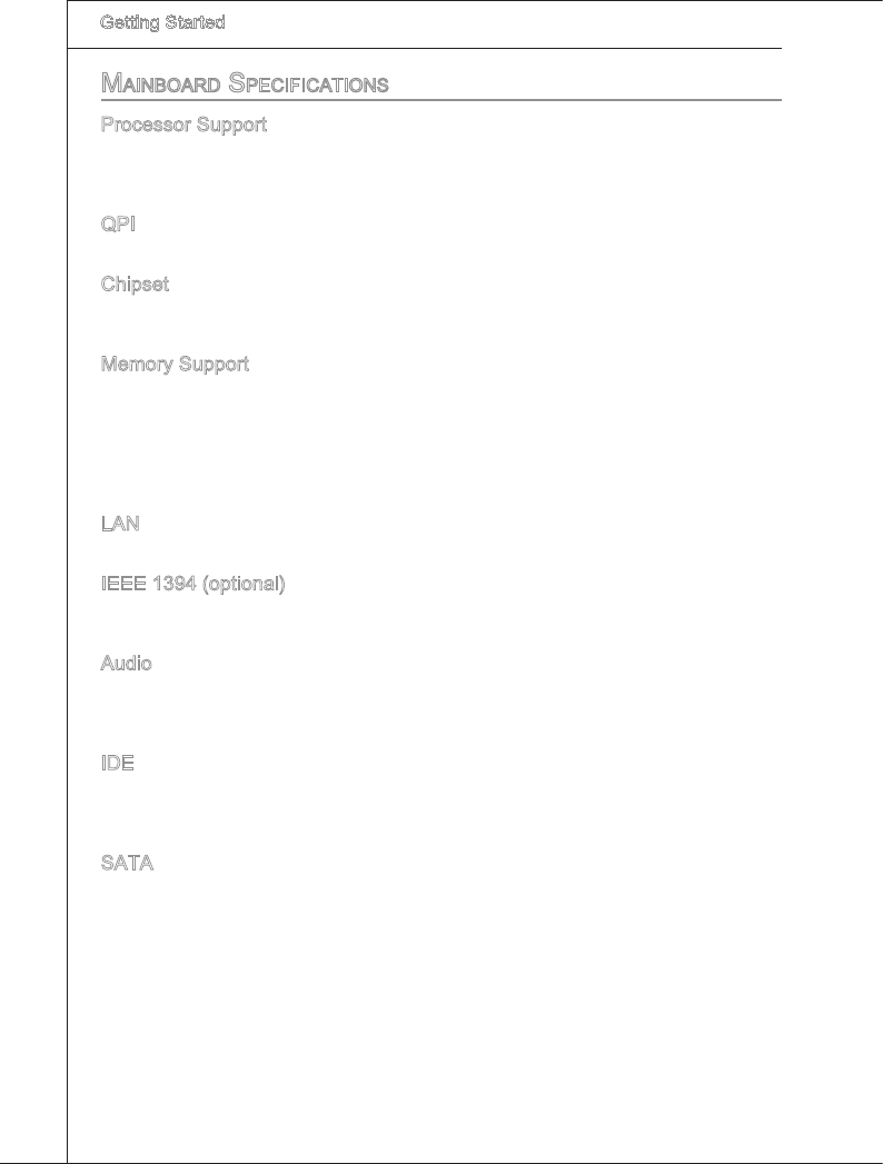
Mainboard SpecificationS
Processor Support
Intel® 7 processor n the LGA1366 package
(For the latest nformaton about CPU, please vst http://global.ms.com.tw/ndex.
php?func=cpuform2)
QPI
Up to 6.4 GT/s
Chpset
North Brdge: Intel® X58 chpset
South Brdge: Intel® ICH10R/ ICH10 (optonal) chpset
Memory Support
6 DDR3 DIMMs support DDR3 1333/ 1066/ 800 DRAM speed (24GB Max)
Supports 1Gb/ 2Gb/ 4Gb DRAM sze
Supports x8/ x16 data lnes per DRAM
Supports Trple-Channel mode
(For more nformaton on compatble components, please vst
http://global.ms.com.tw/ndex.php?func=testreport)
LAN
Supports 10/100/1000 LAN by Realtek® RTL8111C
IEEE 1394 (optonal)
Chp ntegrated by VIA® VT6315N
Transfer rate s up to 400Mbps
Audo
Chp ntegrated by Realtek® ALC888S/ ALC889
Flexble 8-channel audo wth jack sensng
Complant wth Azala 1.0 Spec
IDE
1 IDE port by JMcron® JMB363
Supports Ultra DMA 66/100/133 mode
Supports PIO, Bus Master operaton mode
SATA
6 SATAII (SATA1~6) ports by Intel® ICH10R/ ICH10 (optonal)
1 SATAII (SATA7) port by JMcron® JMB363
1 E-SATA port (back panel) by JMcron® JMB363
Supports storage and data transfers at up to 3 Gb/s
■
■
■
■
■
■
■
■
■
■
■
■
■
■
■
■
■
■
■
■
■
Gettng Started
▍MS-7593
1-3
Gettng Started
▍MS-7593
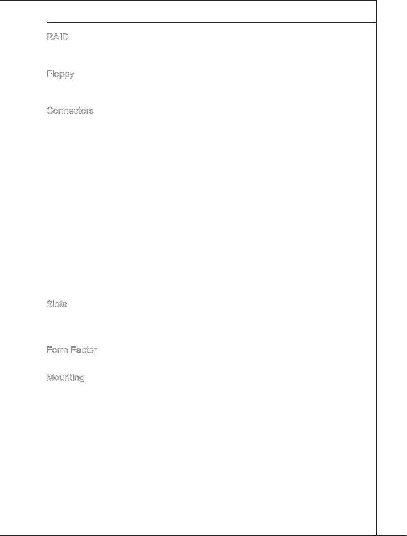
RAID
SATA1~6 support Intel® Matrx Storage Technology (AHCI/ RAID 0/ 1/ 5/ 10) by
ICH10R
Floppy
1 oppy port
Supports 1 FDD wth 360 KB, 720 KB, 1.2 MB, 1.44 MB and 2.88 MB
Connectors
Back panel
1 PS/2 keyboard port
1 PS/2 mouse port
6 USB 2.0 ports
1 E-SATA port
1 IEEE 1394 port (optonal)
1 LAN port
6 exble audo ports
On-Board
3 USB 2.0 connectors
1 IEEE 1394 connector (optonal)
1 Chasss Intruson connector
1 Seral connector
1 CD-In connector
1 Front Panel Audo connector
1 TPM Module connector (optonal)
1 Hardware Overclock Base clock swtch
1 Power button
1 S/PDIF-Out connector
Slots
2 PCI Express 2.0 x16 slots
1 PCI Express 2.0 x4 slot
1 PCI slot, support 3.3V/ 5V PCI bus Interface
Form Factor
Mcro-ATX (24.5cm X 24.5 cm)
Mountng
8 mountng holes
■
■
■
■-
-
-
-
-
-
-
■-
-
-
-
-
-
-
-
-
-
■
■
■
■
■
1-4
Gettng Started
▍MS-7593
Gettng Started
▍MS-7593
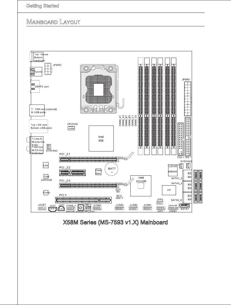
X58M Seres (MS-7593 v1.X) Manboard
Mainboard Layout
Gettng Started
▍MS-7593
1-5
Gettng Started
▍MS-7593
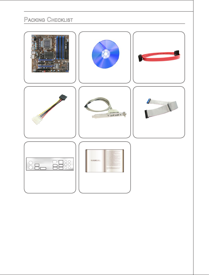
MSI manboard MSI Drver/Utlty DVD SATA Cable (Optonal)
Power Cable USB Bracket (Optonal) Standard Cable for
IDE Devces
Back IO Sheld User’s Gude
packing checkLiSt
* The pctures are for reference only and may vary from the packng contents of the
product you purchased.

2-1
Ths chapter provdes you wth the nformaton about
hardware setup procedures. Whle dong the nstalla-
ton, be careful n holdng the components and follow the
nstallaton procedures. For some components, f you
nstall n the wrong orentaton, the components wll not
work properly.
Use a grounded wrst strap before handlng computer
components. Statc electrcty may damage the compo-
nents.
Chapter 2
Hardware Setup
2-2
Hardware Setup
▍MS-7593
Hardware Setup
▍MS-7593
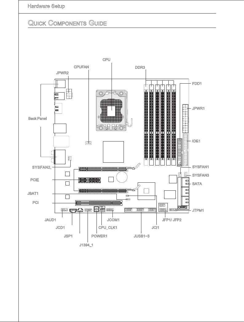
JPWR2, p.2-11
Quick coMponentS guide
Back Panel,
p.2-12
CPU, p.2-3
CPUFAN, p.2-16 DDR3, p.2-7
JCOM1, p.2-18
JCI1, p.2-15
FDD1, p.2-14
JPWR1, p.2-11
IDE1, p.2-14
JTPM1, p.2-20
SATA, p.2-15
SYSFAN1, p.2-16
JFP1/ JFP2, p.2-17
JUSB1~3, p.2-18
JBAT1, p.2-21
J1394_1, p.2-17
JCD1, p.2-16
JAUD1, p.2-19
PCI, p.2-29
PCIE, p.2-24
SYSFAN2,
p.2-16 SYSFAN3, p.2-16
CPU_CLK1, p.2-22
POWER1, p.2-23JSP1, p.2-19
Hardware Setup
▍MS-7593
2-3
Hardware Setup
▍MS-7593
cpu (centraL proceSSing unit)
When you are nstallng the CPU, make sure to nstall the cooler to prevent overheatng.
If you do not have the CPU cooler, consult your dealer before turnng on the computer.
For the latest nformaton about CPU, please vst http://global.ms.com.tw/ndex.
php?func=cpuform2
Important
Overheatng
Overheatng wll serously damage the CPU and system. Always make sure the coolng
fan can work properly to protect the CPU from overheatng. Make sure that you apply
an even layer of thermal paste (or thermal tape) between the CPU and the heatsnk to
enhance heat dsspaton.
Replacng the CPU
Whle replacng the CPU, always turn o the ATX power supply or unplug the power
supply’s power cord from the grounded outlet rst to ensure the safety of CPU.
Overclockng
Ths manboard s desgned to support overclockng. However, please make sure your
components are able to tolerate such abnormal settng, whle dong overclockng. Any
attempt to operate beyond product speccatons s not recommended. We do not guar-
antee the damages or rsks caused by nadequate operaton or beyond product spec-
catons.
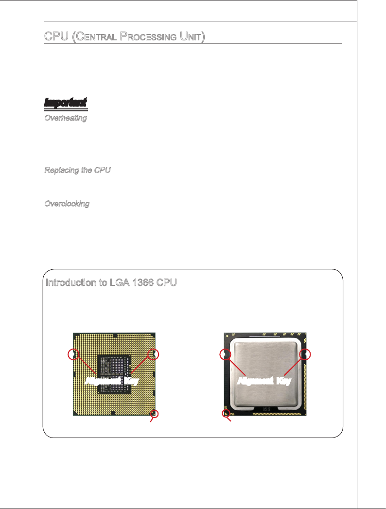
Introducton to LGA 1366 CPU
The pn-pad sde of LGA 1366 CPU. The surface of LGA 1366 CPU. Remem-
ber to apply some thermal paste on t for
better heat dsperson.
Algnment Key
Yellow trangle s the Pn 1 ndcator
Algnment Key
Yellow trangle s the Pn 1 ndcator
2-4
Hardware Setup
▍MS-7593
Hardware Setup
▍MS-7593
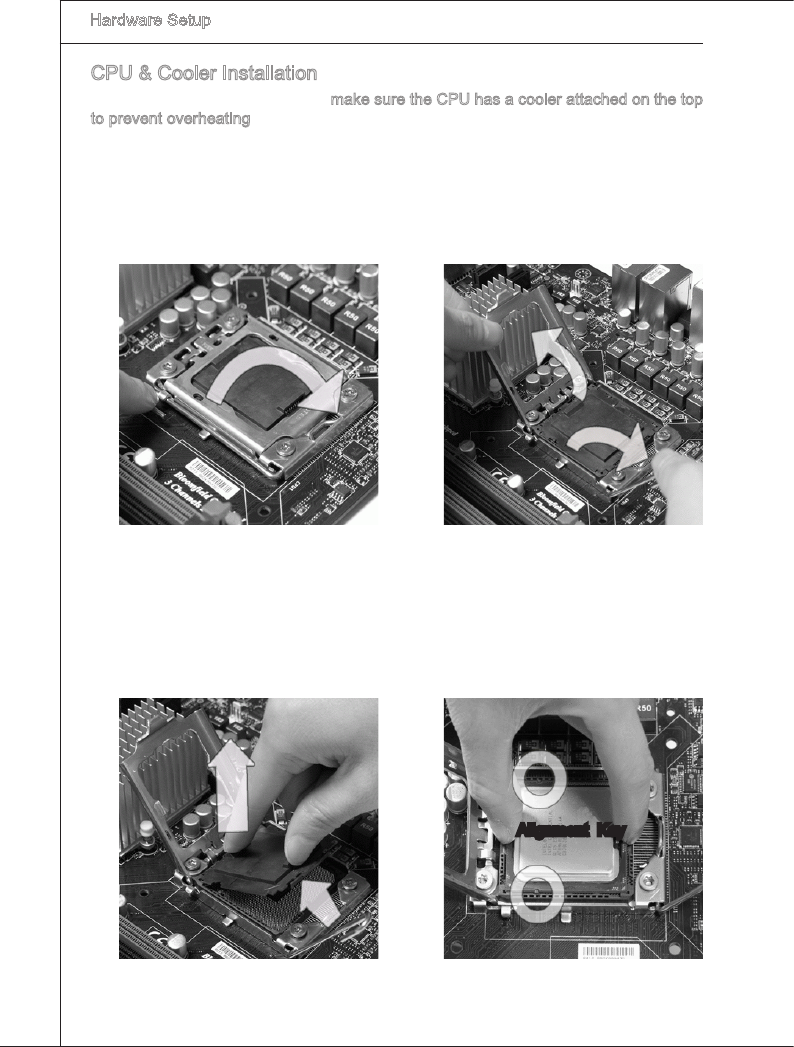
CPU & Cooler Installaton
When you are nstallng the CPU, make sure the CPU has a cooler attached on the top
to prevent overheatng. Meanwhle, do not forget to apply some thermal paste on CPU
before nstallng the heat snk/cooler fan for better heat dsperson.
Follow the steps below to nstall the CPU & cooler correctly. Wrong nstallaton wll
cause the damage of your CPU & manboard.
Open the load level.
1. Lft the load lever up and open the
load plate.
2.
The CPU socket has a plastc cap on
t to protect the contact from damage.
Before you nstall CPU, always cover
t to protect the socket pn. Romove
the cap from the lever hnge sde (as
the arrow shows).
3. After conrmng the CPU drecton for
correct matng, put down the CPU n
the socket housng frame. Be sure to
grasp on the edge of the CPU base.
Note that the algnment keys are
matched.
4.
Algnment Key
Hardware Setup
▍MS-7593
2-5
Hardware Setup
▍MS-7593
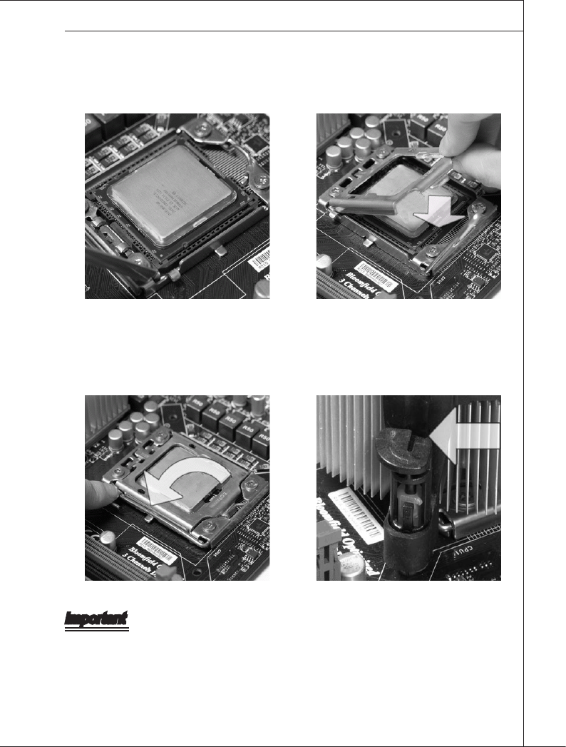
Vsually nspect f the CPU s seated
well nto the socket. If not, take out
the CPU wth pure vertcal moton
and renstall.
5. Cover the load plate onto the pack-
age.
6.
Press down the load lever lghtly onto
the load plate, and then secure the
lever wth the hook under retenton
tab.
7. Make sure the four hooks are n por-
per poston before you nstall the
cooler.
8.
Important
Conrm f your CPU cooler s rmly nstalled before turnng on your system.
Do not touch the CPU socket pns to avod damagng.
•
•
2-6
Hardware Setup
▍MS-7593
Hardware Setup
▍MS-7593
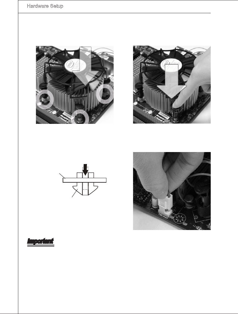
Manboard
Hook
Important
Read the CPU status n BIOS.
Whenever CPU s not nstalled, always protect your CPU socket pn wth the plastc
cap covered (shown n Fgure 1) to avod damagng.
Manboard photos shown n ths secton are for demonstraton of the CPU/ cooler n-
stallaton only. The appearance of your manboard may vary dependng on the model
you purchase.
Please refer to the documentaton n the CPU fan package for more detals about the
CPU fan nstallaton.
•
•
•
•
Algn the holes on the manboard wth
the heatsnk. Push down the cooler
untl ts four clps get wedged nto the
holes of the manboard.
9. Press the four hooks down to fasten
the cooler.
10.
Turn over the manboard to conrm
that the clp-ends are correctly n-
serted.
11. Fnally, attach the CPU Fan cable to
the CPU fan connector on the man-
board.
12.
Hardware Setup
▍MS-7593
2-7
Hardware Setup
▍MS-7593
MeMory
These DIMM slots are used for nstallng memory modules. For more nformaton on com-
patble components, please vst
http://global.ms.com.tw/ndex.php?func=testreport
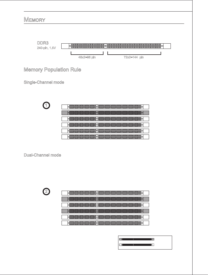
DDR3
240-pn, 1.5V
48x2=96 pn 72x2=144 pn
Memory Populaton Rule
Please refer to the followng llustratons for memory populaton rules.
Sngle-Channel mode
When you have only one memory module, please always nsert t nto the DIMM_A0 rst
(as way 1 shown n below).
1 DIMM_A1
DIMM_A0
DIMM_B1
DIMM_B0
DIMM_C1
DIMM_C0
Dual-Channel mode
In Dual-Channel mode, the memory modules can transmt and receve data wth two
data bus lnes smultaneously. Enablng Dual-Channel mode can enhance the system
performance. When you have two memory modules, please always nsert them nto the
DIMM_A0 & DIMMB0 (as way 2 shown n below).
2 DIMM_A1
DIMM_A0
DIMM_B1
DIMM_B0
DIMM_C1
DIMM_C0
Installed
Empty
2-8
Hardware Setup
▍MS-7593
Hardware Setup
▍MS-7593
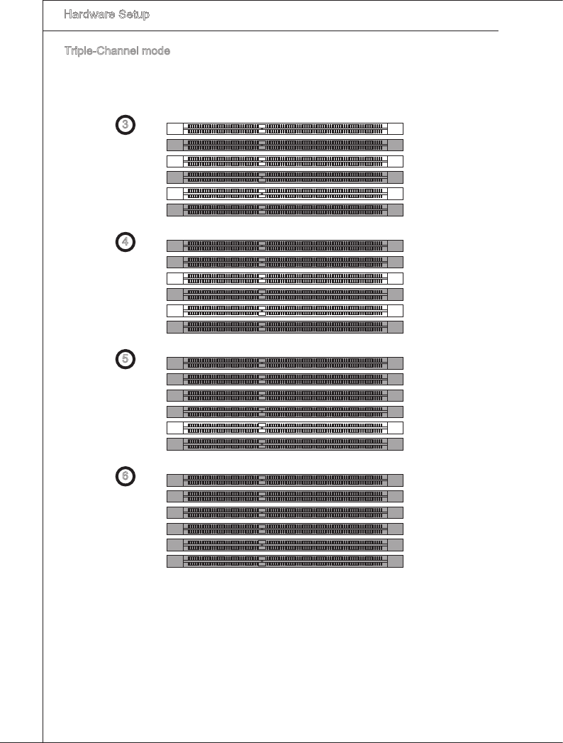
Trple-Channel mode
In Trple-Channel mode, the memory modules can transmt and receve data wth three
data bus lnes smultaneously. Enablng Trple-Channel mode can enhance the best
system performance. When you have three or more memory modules, please always
nsert them as the way 3/ 4/ 5/ 6 (shown n below) to get the best system performance.
` 3 DIMM_A1
DIMM_A0
DIMM_B1
DIMM_B0
DIMM_C1
DIMM_C0
4 DIMM_A1
DIMM_A0
DIMM_B1
DIMM_B0
DIMM_C1
DIMM_C0
5 DIMM_A1
DIMM_A0
DIMM_B1
DIMM_B0
DIMM_C1
DIMM_C0
6 DIMM_A1
DIMM_A0
DIMM_B1
DIMM_B0
DIMM_C1
DIMM_C0
Hardware Setup
▍MS-7593
2-9
Hardware Setup
▍MS-7593
Important
DDR3 memory modules are not nterchangeable wth DDR2 and the DDR3 standard
DDR3 memory modules are not nterchangeable wth DDR2 and the DDR3 standard
s not backwards compatble. You should always nstall DDR3 memory modules n
the DDR3 DIMM slots.
In Trple channel/ Dual channel mode, make sure that you nstall memory modules of
the same type and densty n derent channel DIMM slots. If the speeds of nstalled
memeory modules are derent (ex. 1066 & 1333), the system wll detect and operate
the lower speed (1066) wth all nstalled memory modules.
Please always nstall the same type and densty memory modules n DIMM slots to
avod the damage of memory.
To enable successful system boot-up, always nsert the memory modules nto the
DIMM_A0 rst.
Due to the chpset resource deployment, the system densty wll only be detected up
to 23+GB (not full 24GB) when each DIMM s nstalled wth a 4GB memory module.
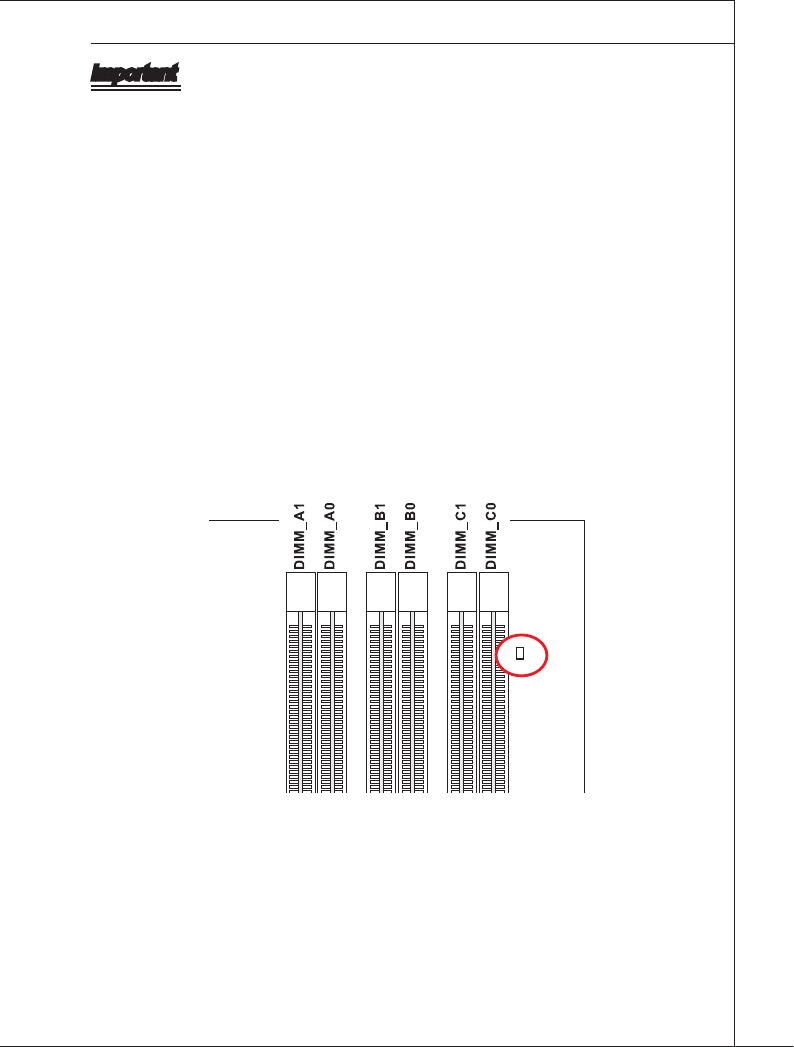
When you nstall ncorrect memory module (the SA2-pn of the memory module con-
nects to Ground) n the DIMM_C0/C1, the LED besde DIMM_C0 wll lght red color
to remnd you. The poston of the LED s shown as below. Double conrm wth your
memory module vender for the thrd channelsupports.
•
•
•
•
•
•
2-10
Hardware Setup
▍MS-7593
Hardware Setup
▍MS-7593
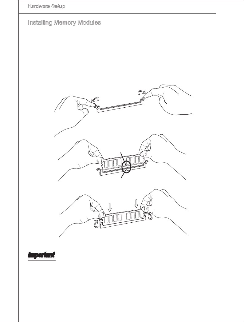
Installng Memory Modules
The memory module has only one notch on the center and wll only t n the rght
orentaton.
Insert the memory module vertcally nto the DIMM slot. Then push t n untl the
golden nger on the memory module s deeply nserted n the DIMM slot. The plastc
clp at each sde of the DIMM slot wll automatcally close when the memory module
s properly seated.
Manually check f the memory module has been locked n place by the DIMM slot
clps at the sdes.
Notch
Volt
Important
You can barely see the golden nger f the memory module s properly nserted n the
DIMM slot.
1.
2.
3.
Hardware Setup
▍MS-7593
2-11
Hardware Setup
▍MS-7593
power SuppLy
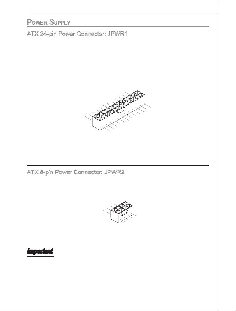
ATX 24-pn Power Connector: JPWR1
Ths connector allows you to connect an ATX 24-pn power supply. To connect the ATX
24-pn power supply, make sure the plug of the power supply s nserted n the proper
orentaton and the pns are algned. Then push down the power supply rmly nto the
connector.
You may use the 20-pn ATX power supply as you lke. If you’d lke to use the 20-pn
ATX power supply, please plug your power supply along wth pn 1 & pn 13.
13.+3.3V
1.+3.3V
14.-12V
2.+3.3V
15.Ground
3.Ground
16.PS-ON#
4.+5V17.Ground
5.Ground
18.Ground
6.+5V
19.Ground
7.Ground
22.+5V
10.+12V
20.Res
8.PWR OK
23.+5V
11.+12V
21.+5V
9.5VSB
24.Ground
12.+3.3V
ATX 8-pn Power Connector: JPWR2
Ths connector s used to provde 12V power output to the CPU.
7.+12V
3.Ground
5.+12V
1.Ground
8.+12V
4.Ground
6.+12V
2.Ground
Important
Make sure that all the connectors are connected to proper ATX power supples to
ensure stable operaton of the manboard.
Power supply of 400 watts (and above) s hghly recommended for system stablty.
ATX 12V power connecton should be greater than 18A.
•
•
•

2-12
Hardware Setup
▍MS-7593
Hardware Setup
▍MS-7593
back paneL
Mouse/Keyboard
The standard PS/2® mouse/keyboard DIN connector s for a PS/2® mouse/keyboard.
VGA Port
USB Port
The USB (Unversal Seral Bus) port s for attachng USB devces such as keyboard,
mouse, or other USB-compatble devces.
E-SATA Port
The E-SATA (External-SATA) port s for attachng the E-SATA hard drve.
1394 Port (optonal)
The IEEE1394 port on the back panel provdes connecton to IEEE1394 devces.
LAN
The standard RJ-45 LAN jack s for connecton to
the Local Area Network (LAN). You can connect a
network cable to t.
LED Color LED State Condton
Left Yellow O LAN lnk s establshed.
On(Steady state) LAN lnk s establshed.
On(brghter & pulsng) The computer s communcatng wth another computer on the LAN.
Rght Green O 10 Mbts/sec data rate s selected.
On 100 Mbts/sec data rate s selected.
Orange On 1000 Mbts/sec data rate s selected.
▶
▶
▶
▶
▶
Mouse (optonal)
1394 Port
USB Port
LAN
Lne-In
Lne-Out
Mc
RS-Out
CS-Out
SS-Out
USB PortE-SATA PortUSB Port
Yellow Green/ Orange
Keyboard

Hardware Setup
▍MS-7593
2-13
Hardware Setup
▍MS-7593
Audo Ports
These audo connectors are used for audo devces. It s easy to derentate between
audo eects accordng to the color of audo jacks.
Lne-In (Blue) - Lne In, s used for external CD player, tape-player or other
audo devces.
Lne-Out (Green) - Lne Out, s a connector for speakers or headphones.
Mc (Pnk) - Mc, s a connector for mcrophones.
RS-Out (Black) - Rear-Surround Out n 4/ 5.1/ 7.1 channel mode.
CS-Out (Orange) - Center/ Subwoofer Out n 5.1/ 7.1 channel mode.
SS-Out (Gray) - Sde-Surround Out 7.1 channel mode.
▶
■
■
■
■
■
■
2-14
Hardware Setup
▍MS-7593
Hardware Setup
▍MS-7593
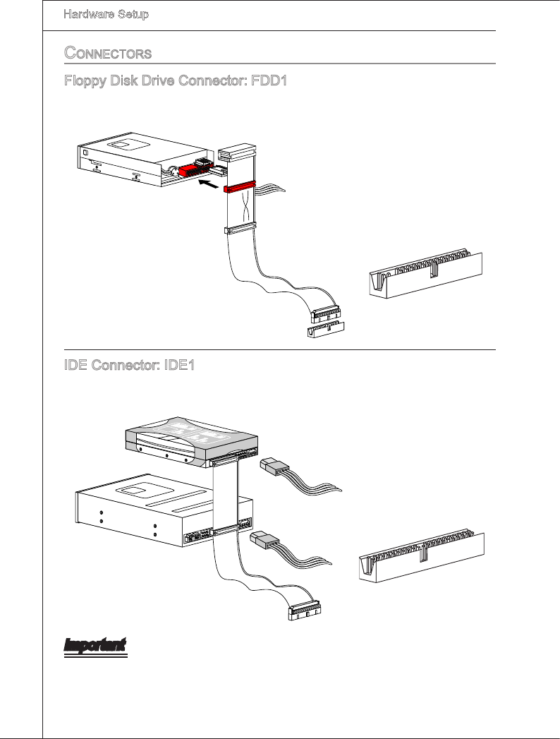
connectorS
Floppy Dsk Drve Connector: FDD1
Ths connector supports 360 KB, 720 KB, 1.2 MB, 1.44 MB or 2.88 MB oppy dsk
drve.
Floppy D
MS
I
Kd
kl
kdkfk
kkfdkkl
ddfkkksd
dfdd
f
a
sdka
d
f - d
d
fdd
ad
dfdfd
dd
dd
fa
df
a
dkja
sjdkdfdfasd
d
dffa
sd
fdd
ddd
d
dfda
sfda
sasdf
a
sd
a
sd
asd
ddd
dd
dfa
s
a
sdfsdffsdf
ad
fffa
sdfffdf
3 1/2" Flo
ppy Disk Drive
Co
nne
c
tor
3 1/2" Flo
ppy Disk Drive
Co
nne
c
tor
5 1/4" Floppy
Disk Drive
Conne
c
tor
IDE Connector: IDE1
Ths connector supports IDE hard dsk drves, optcal dsk drves and other IDE de-
vces.
CD-ROM
MSI
Kdkl kd
kfk kkfdkkl
ddfkkks
d dfddf
a
sdka df - d dfdd
addfdfdddd
dfadf
adkjasjdkdfdfa
sd
ddffa
sdfdddddd
dfda
sfdasas
df
a
sd
as
d
a
sdddddddfas
as
dfs
dffsdf
adfffasdfffdf
Floppy D
MS
I
Floppy D
MSI
Kd
kl kdkfk
kkfd
kkl
dd
fkkksd
dfd
df
as
dka
df - d
dfd
d
a
dd
fd
fddd
ddfa
df
a
dkja
s
jdkd
fd
fasd
ddffa
sd
fd
dd
ddd
d
fdas
fda
sa
sdf
a
sd
as
d
a
sd
dd
ddd
dfas
as
dfs
dffsdf
adfffas
d
fffdf
Floppy D
MS
I
Kdkl kd
kfk kkfdkkl
ddfkkks
d
dfdd
f
a
s
dka
d
f - d
dfdd
a
ddfdfd
ddd
dfad
f
ad
kjas
jdkdfdfa
sd
d
dffasdfdd
dd
dd
dfd
as
fdas
a
sd
f
asd
a
sd
as
dd
dd
ddd
fa
s
as
dfsdffsd
f
a
dfffasdfffdf
3 1/2" Floppy Disk Drive
Conne
ctor
3 1/2" Flop
py Disk Drive
Conne
c
tor
Important
If you nstall two IDE devces on the same cable, you must congure the drves sepa-
rately to master / slave mode by settng jumpers. Refer to IDE devce’s documentaton
suppled by the vendors for jumper settng nstructons.
Hardware Setup
▍MS-7593
2-15
Hardware Setup
▍MS-7593
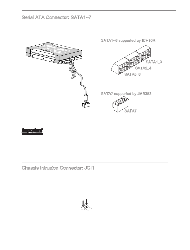
Seral ATA Connector: SATA1~7
Ths connector s a hgh-speed Seral ATA nterface port. Each connector can connect
to one Seral ATA devce.
Floppy D
MS
I
Floppy D
MSI
Kd
kl kdkfk kkfd
kkl
dd
fkkksd
dfd
df
as
dka
df - d
dfdd
a
dd
fd
fddd
ddfa
df
a
dkja
sjd
kd
fd
fasd
ddffa
sd
fd
dd
ddd
d
fdasfda
sa
s
df
as
d
as
d
a
sd
dd
ddd
dfas
asdfs
dffs
df
adfffas
dfffdf
Floppy D
MS
I
Kdkl kd
kfk kkfdkkl
ddfkkks
d
dfdd
f
a
s
dka
d
f - d
dfdd
a
ddfdfd
ddd
dfad
f
ad
kjas
jdkdfdfa
sd
d
dffas
dfdd
dd
dd
dfd
as
fdasa
sd
f
as
d
a
sd
as
dd
ddd
dd
fa
s
as
dfsdffsd
f
a
dfffasdfffdf
SATA5_6
SATA2_4
SATA1_3
SATA7
SATA1~6 supported by ICH10R
SATA7 supported by JMB363
Important
Please do not fold the Seral ATA cable nto 90-degree angle. Otherwse, data loss may
occur durng transmsson.
Chasss Intruson Connector: JCI1
Ths connector connects to the chasss ntruson swtch cable. If the chasss s opened,
the chasss ntruson mechansm wll be actvated. The system wll record ths status
and show a warnng message on the screen. To clear the warnng, you must enter the
BIOS utlty and clear the record.
1.CINTRU
2.Ground
2-16
Hardware Setup
▍MS-7593
Hardware Setup
▍MS-7593
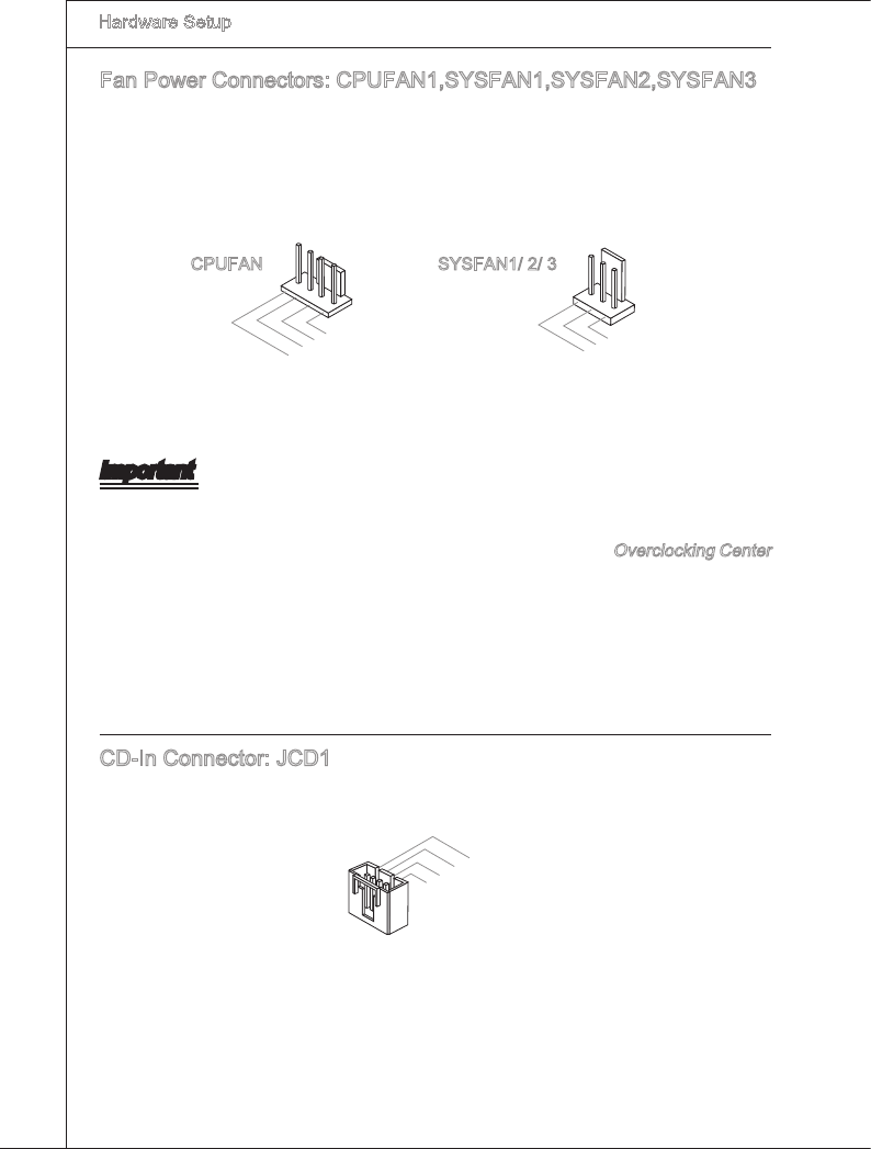
Fan Power Connectors: CPUFAN1,SYSFAN1,SYSFAN2,SYSFAN3
The fan power connectors support system coolng fan wth +12V. When connectng the
wre to the connectors, always note that the red wre s the postve and should be con-
nected to the +12V; the black wre s Ground and should be connected to GND. If the
manboard has a System Hardware Montor chpset on-board, you must use a specally
desgned fan wth speed sensor to take advantage of the CPU fan control.
1.Ground
2.+12V
3.Sensor
4.Control
1.Ground
2.+12V
3.Sensor
CPUFAN SYSFAN1/ 2/ 3
Important
Please refer to the recommended CPU fans at processor’s ocal webste or consult
the vendors for proper CPU coolng fan.
CPUFAN & SYSFAN1 support Smart fan control. You can nstall Overclockng Center
utlty that wll automatcally control the CPUFAN & SYSFAN1 speeds accordng to
the actual CPUFAN & SYSFAN1 temperatures.
Fan cooler set wth 3 or 4 pns power connector are both avalable for CPUFAN.
CD-In Connector: JCD1
Ths connector s provded for external audo nput.
4.R
3.Ground
2.Ground
1.L
•
•
•
Hardware Setup
▍MS-7593
2-17
Hardware Setup
▍MS-7593
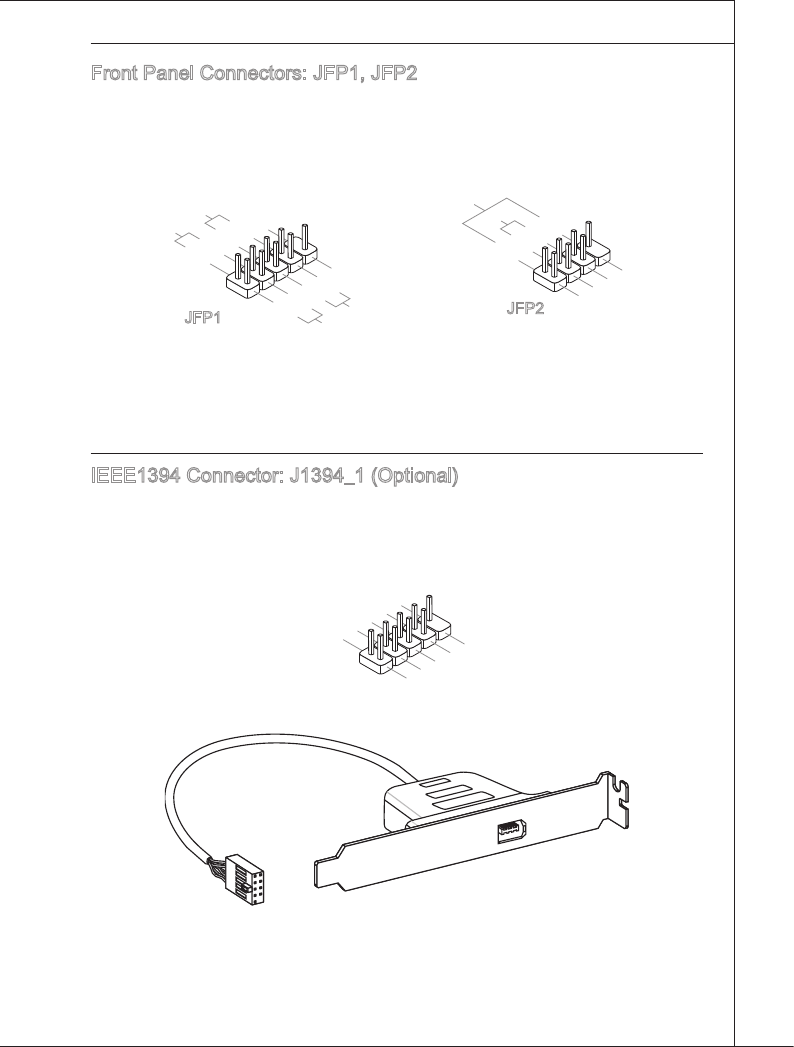
Front Panel Connectors: JFP1, JFP2
These connectors are for electrcal connecton to the front panel swtches and LEDs.
The JFP1 s complant wth Intel?Front Panel I/O Connectvty Desgn Gude.
1.Ground
3.Suspend LED
5.Power LED
7.No Pin
8.+
6.-
4.+
2.-
Buzzer
Speaker
1.+
3.-
10.No Pin
5.-Reset Switch
HDD LED
Power Switch
Power LED
7.+
9.Reserved
8.-
6.+
4.-
2.+
JFP1 JFP2
IEEE1394 Connector: J1394_1 (Optonal)
Ths connector allows you to connect the IEEE1394 devce va an optonal IEEE1394
bracket.
1.TPA+
3.Ground
10.Ground
5.TPB+
7.+12V
9.No Pin
8.+12V
6.TPB-
4.Ground
2.TPA-
IEEE1394 Bracket (optonal)
2-18
Hardware Setup
▍MS-7593
Hardware Setup
▍MS-7593
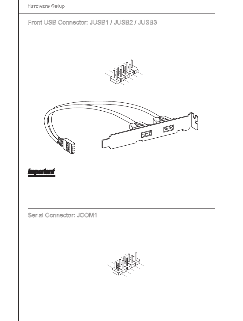
Front USB Connector: JUSB1 / JUSB2 / JUSB3
Ths connector, complant wth Intel® I/O Connectvty Desgn Gude, s deal for con-
nectng hgh-speed USB nterface perpherals such as USB HDD, dgtal cameras, MP3
players, prnters, modems and the lke.
USB 2.0 Bracket (optonal)
1.VCC
3.USBD-
10.USBOC
5.USBD+
7.Ground
9.No Pin
8.Ground
6.USBD+
4.USBD-
2.VCC
Important
Note that the pns of VCC and GND must be connected correctly to avod possble
damage.
Seral Connector: JCOM1
Ths connector s a 16550A hgh speed communcaton port that sends/ receves 16
bytes FIFOs. You can attach a seral devce.
1.DCD
3.SOUT
10.No Pin
5.Ground
7.RTS
9.RI
8.CTS
6.DSR
4.DTR
2.SIN
Hardware Setup
▍MS-7593
2-19
Hardware Setup
▍MS-7593
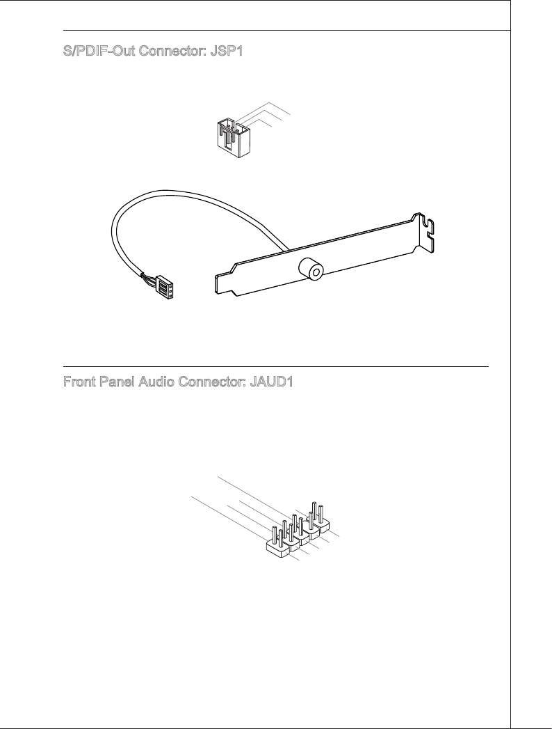
S/PDIF-Out Connector: JSP1
Ths connector s used to connect S/PDIF (Sony & Phlps Dgtal Interconnect Format)
nterface for dgtal audo transmsson.
1.VCC
2.SPDIF
3.Ground
S/PDIF Bracket (Optonal)
Front Panel Audo Connector: JAUD1
Ths connector allows you to connect the front panel audo and s complant wth Intel®
Front Panel I/O Connectvty Desgn Gude.
1.MIC L
3.MIC R
10.Head Phone Detection
5.Head Phone R
7.SENSE_SEND
9.Head Phone L
8.No Pin
6.MIC Detection
4.PRESENCE#
2.Ground
2-20
Hardware Setup
▍MS-7593
Hardware Setup
▍MS-7593
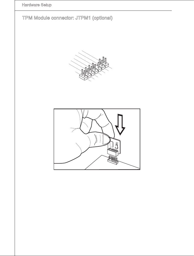
TPM Module connector: JTPM1 (optonal)
Ths connector connects to a TPM (Trusted Platform Module) module (optonal). Please
refer to the TPM securty platform manual for more detals and usages.
10.No Pin
14.Ground
8.5V Power
12.Ground
6.Serial IRQ
4.3.3V Power
2.3V Standby power1.LPC Clock
3.LPC Reset
5.LPC address & data pin0
7.LPC address & data pin1
9.LPC address & data pin2
11.LPC address & data pin3
13.LPC Frame
Hardware Setup
▍MS-7593
2-21
Hardware Setup
▍MS-7593
JuMperS
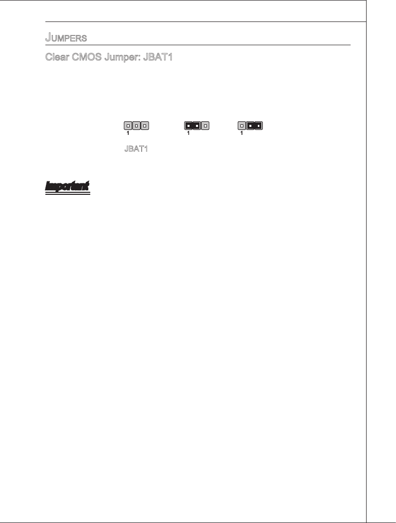
Clear CMOS Jumper: JBAT1
There s a CMOS RAM onboard that has a power supply from an external battery to
keep the data of system conguraton. Wth the CMOS RAM, the system can automat-
cally boot OS every tme t s turned on. If you want to clear the system conguraton,
set the jumper to clear data.
JBAT1 Keep Data Clear Data
1 11
Important
You can clear CMOS by shortng 2-3 pn whle the system s o. Then return to 1-2
pn poston. Avod clearng the CMOS whle the system s on; t wll damage the man-
board.
2-22
Hardware Setup
▍MS-7593
Hardware Setup
▍MS-7593
Switch
Ths manboard provdes the followng swtch for you to set the computer’s functon.
Ths secton wll explan how to change your manboard’s functon through the use of
swtch.
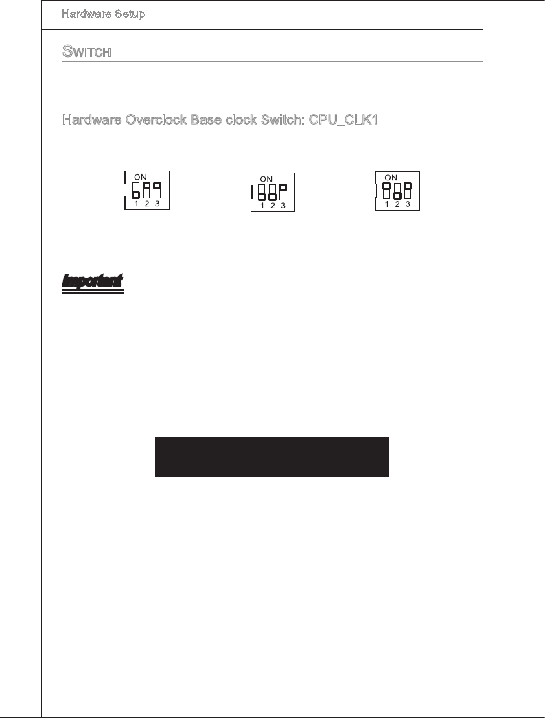
Hardware Overclock Base clock Swtch: CPU_CLK1
You can overclock the Base clock to ncrease the processor frequency by changng ths
swtch. Follow the nstructons below to set the base clock.
133 MHz
(default)
166 MHz 200 MHz
Important
Make sure that you power o the system before changng the swtch.
Ths overclockng behavor depends on the system’s conguraton (memory capabl-
ty, thermal soluton...etc), and t s not guaranteed.
You can also overclock by settng BIOS. BIOS overclockng may also cause crash
durng boot and then please reboot the system 3 tmes to restore default BIOS set-
tngs. For more detals, please refer to the BIOS chapter.
When overclockng cause nstablty or crash durng boot, the followng warnng mes-
sage wll dsplay durng POST (as pcture below). And then, please re-set the swtch
to default.
Warnng!!! OC swtch overclockng had faled,
Please shutdown and adjust oc swtch to lower frequency.
Try agan!
•
•
•
•
Hardware Setup
▍MS-7593
2-23
Hardware Setup
▍MS-7593
button
The manboard provdes the followng button for you to set the computer’s functon.
Ths secton wll explan how to change your manboard’s functon through the use of
button.
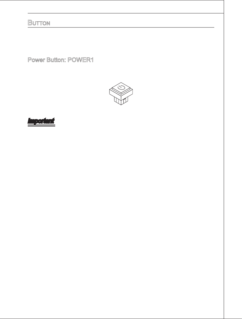
Power Button: POWER1
Ths power button s used to turn-on or turn-o the system. Press the button to turn-on
or turn-o the system.
Important
Ths button wll lght whsn system s power-on.
2-24
Hardware Setup
▍MS-7593
Hardware Setup
▍MS-7593
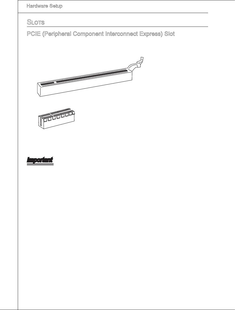
SLotS
PCIE (Perpheral Component Interconnect Express) Slot
The PCI Express slot supports the PCI Express nterface expanson card.
PCI Express 2.0x16 Slot
PCI Express 2.0x4 Slot
Important
When addng or removng expanson cards, make sure that you unplug the power sup-
ply rst. Meanwhle, read the documentaton for the expanson card to congure any
necessary hardware or software settngs for the expanson card, such as jumpers,
swtches or BIOS conguraton.
Hardware Setup
▍MS-7593
2-25
Hardware Setup
▍MS-7593
Important
Manboard photos shown n ths secton are for demonstraton only. The appearance
of your rwk may vary dependng on the model you purchase.
If you ntend to nstall TWO graphcs cards for CrossFreX
TM
mode, make sure that
these two graphcs cards are of the same brand.
Make sure that you connect an adequate power supply to the power connector on the
graphcs card to ensure stable operaton of the graphcs card.
Only Wndows
®
XP wth Servce Pack 2 (SP2)& Wndows
®
XP Professonal x64 Ed-
ton & Wndows
®
Vsta support the CrossFreX
TM
functon.
•
•
•
•
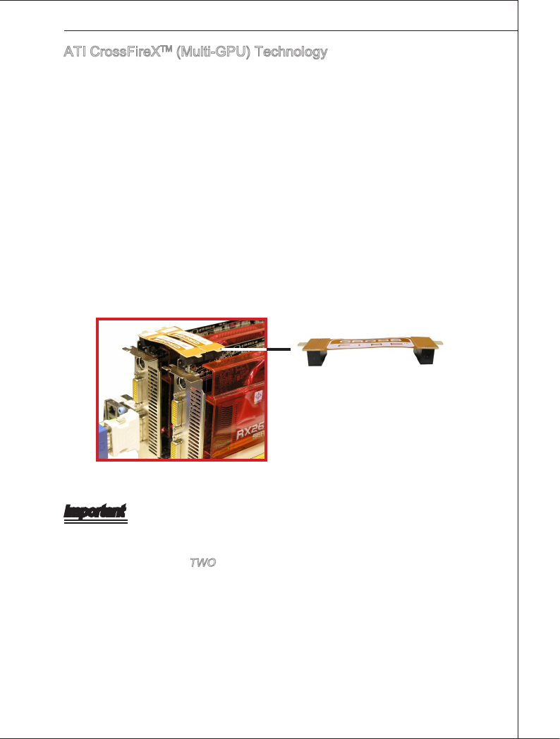
ATI CrossFreXTM (Mult-GPU) Technology
ATI CrossFreXTM s the ultmate mult-GPU performance gamng platform. Enablng
game-domnatng power, ATI CrossFreXTM technology enables two or more dscrete
graphcs processors to work together to mprove system performance. ATI CrossF-
reXTM technology allows you to expand your system’s graphcs capabltes. It allows
you the ablty to scale your system’s graphcs horsepower as you need t, supportng
two ATI RadeonTM HD graphcs cards, makng ths the most scalable gamng platform
ever. The manboard can auto detect the CrossFreXTM mode by software, therefore you
don’t have to enable the CrossFreXTM n BIOS by yourself. The followng detals the
CrossFreXTM nstallaton.
Install one ATI RadeonTM HD graphcs card n rst PCIE x16 slot , then nstall one
ATI RadeonTM HD graphcs card n second PCIE x16 slot.
Wth two cards nstalled, an CrossFreXTM Vdeo Lnk cable s requred to connect
the golden ngers on the top of these two graphcs cards (refer to the pcture be-
low). Please note that although you have nstalled two graphcs cards, only the
vdeo outputs on the graphcs card nstalled n rst PCIE x16 slot wll work. Hence,
you only need to connect a montor to ths graphcs card.
1.
2.
CrossFreXTM Vdeo Lnk cable
2-26
Hardware Setup
▍MS-7593
Hardware Setup
▍MS-7593
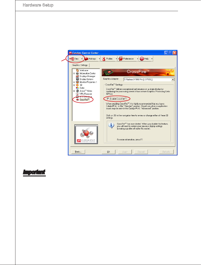
When all of the hardware and software has been properly set up and nstalled, re-
boot the system. After enterng the O.S., clck the “CatalystTM Control Center” con
on the desktop. There s a settng n the CatalystTM Control Center that needs to be
enabled for CrossFreXTM to operate. The followng aspect appears n CatalystTM
Control Center:
3.
Select the Advanced Vew
from the vew drop menu.
Important
A CrossFreX
TM
system has four possble dsplay modes:
SuperTlng
Scssor Mode
Alternate Frame Renderng
Super Ant-alasng.
for more detals, please consult the graphcs card manual from the manufacturer.
•
•
•
•
Hardware Setup
▍MS-7593
2-27
Hardware Setup
▍MS-7593
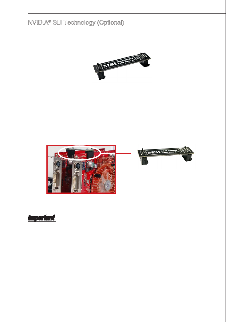
NVIDIA® SLI Technology (Optonal)
NVIDIA® SLI (Scalable Lnk Interface) technology allows two GPUs to run n tandem
wthn a system to acheve up to twce the performance of a sngle graphcs card. To ut-
lze ths technology, the two GPU cards must be connected by an SLI Vdeo Lnk card.
SLI Vdeo Lnk Card
If you ntend to use the SLI mode for better graphcs performance, please refer to the
followng nstructons.
Install two graphcs cards on PCI Express x16 slots. Wth two cards nstalled, an SLI
Vdeo Lnk Card s requred to connect the golden ngers on the top of these two
graphcs cards (refer to the pcture below). Please note that although you have n-
stalled two graphcs cards, only the vdeo outputs on the rst card wll work. Hence,
you only need to connect a montor to the rst PCI Express card.
1.
SLI Vdeo Lnk Card
Important
The photos shown n ths secton are for demonstraton only. The appearance of your
manboard may vary dependng on the model you purchase.
If you ntend to nstall TWO x16 graphcs cards, make sure that these two graphcs
cards are of the same brand and speccatons.
Make sure that you connect an adequate power supply to the power connector on the
graphcs card to ensure stable operaton of the graphcs card.
•
•
•
2-28
Hardware Setup
▍MS-7593
Hardware Setup
▍MS-7593
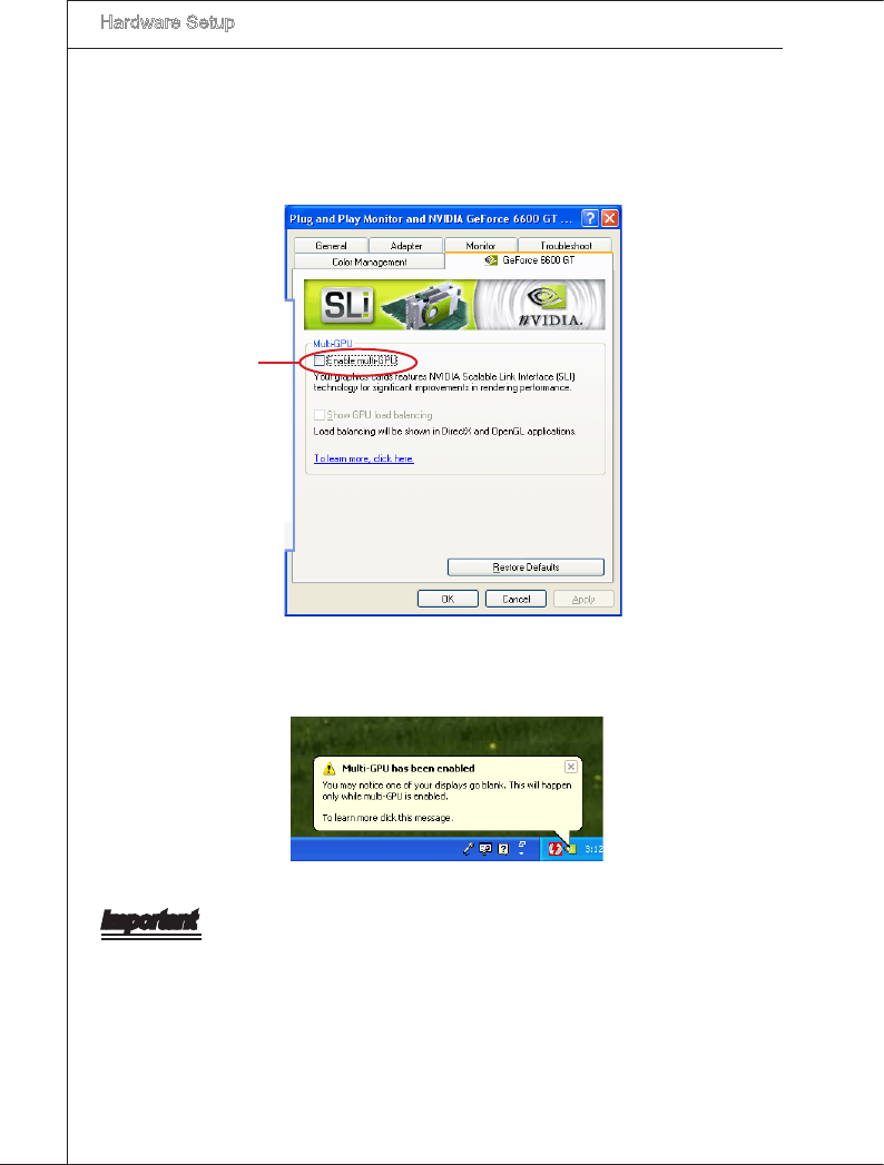
After the hardware nstallaton s completed, restart the system and nstall the NV
SLI drver/utlty. A conguraton panel wll be provded for Mult-GPU control. Check
the Enable mult-GPU box to enable the SLI functon for the onboard graphcs cards
(concernng the detals of mult-GPU settngs, please refer to your graphcs card
manual).
2.
Check the box
Restart your system and a pop-up message wll show n the system tray conrmng
the Mult-GPU has been enabled.
3.
Important
If you want to remove one graphcs card and qut the SLI functon, make sure the “Mul-
tGPU” functon s dsabled.
Hardware Setup
▍MS-7593
2-29
Hardware Setup
▍MS-7593
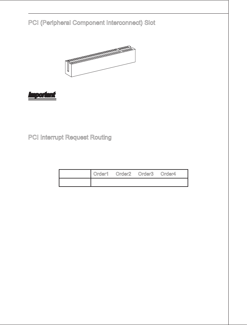
PCI (Perpheral Component Interconnect) Slot
The PCI slot supports LAN card, SCSI card, USB card, and other add-on cards that
comply wth PCI speccatons.
32-bt PCI Slot
Important
When addng or removng expanson cards, make sure that you unplug the power sup-
ply rst. Meanwhle, read the documentaton for the expanson card to congure any
necessary hardware or software settngs for the expanson card, such as jumpers,
swtches or BIOS conguraton.
PCI Interrupt Request Routng
The IRQ, acronym of nterrupt request lne and pronounced I-R-Q, are hardware lnes
over whch devces can send nterrupt sgnals to the mcroprocessor. The PCI IRQ pns
are typcally connected to the PCI bus pns as follows:
Order1 Order2 Order3 Order4
PCI Slot1 INT E# INT F# INT G# INT H#
2-30
Hardware Setup
▍MS-7593
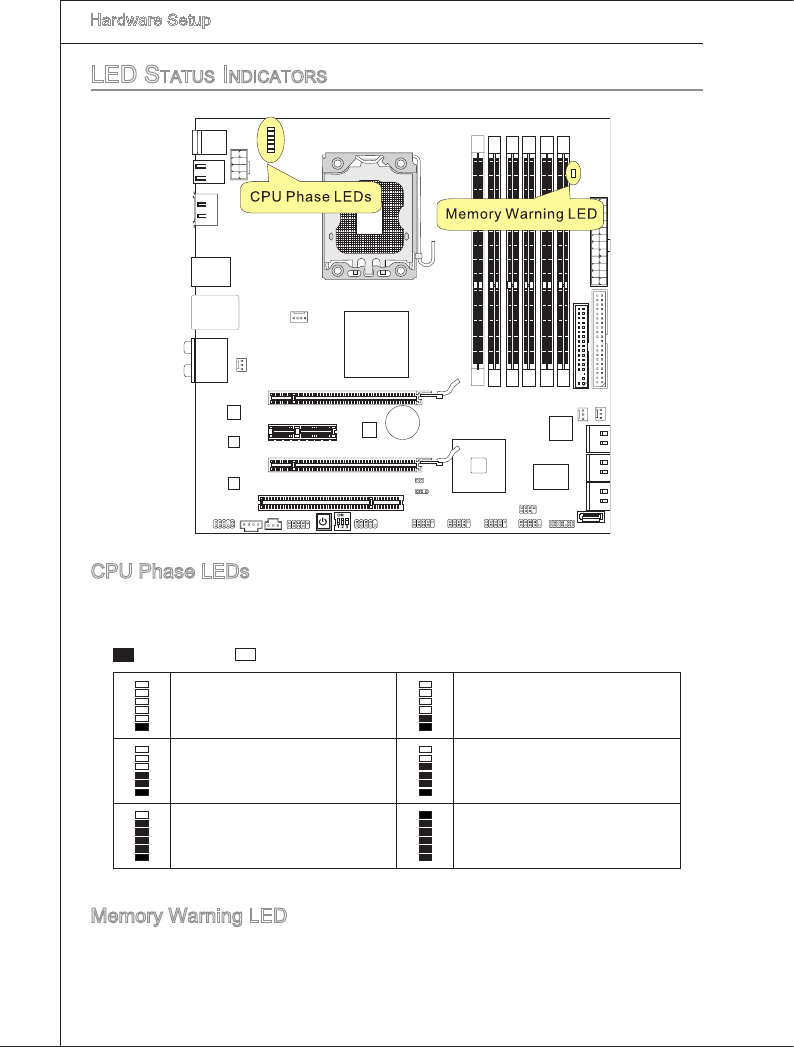
Led StatuS indicatorS
CPU Phase LEDs
These LEDs ndcate the current CPU power phase mode. Follow the nstructons below
to read.
Lghts O
CPU s n 1 phase power mode. CPU s n 2 phase power mode.
CPU s n 3 phase power mode. CPU s n 4 phase power mode.
CPU s n 5 phase power mode. CPU s n 6 phase power mode.
Memory Warnng LED
Lghts red when the ncorrect memory nstalled nto DIMM_C0/ DIMM_C1 (the DIMMs
of 3rd channel).

2-1
Ths chapter provdes nformaton on the BIOS Setup
program and allows you to congure the system for op-
tmum use.
You may need to run the Setup program when:
An error message appears on the screen durng
the system bootng up, and requests you to run
SETUP.
You want to change the default settngs for cus-
tomzed features.
■
■
Chapter 3
BIOS Setup
3-2
BIOS Setup
▍MS-7593
BIOS Setup
▍MS-7593
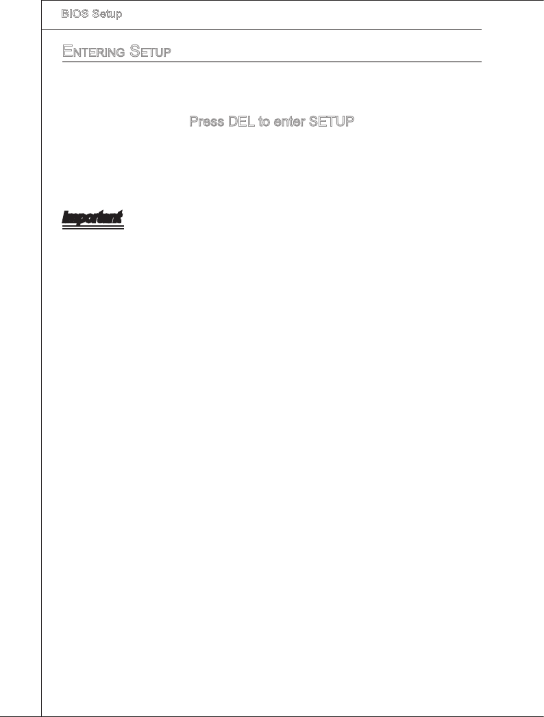
entering Setup
Power on the computer and the system wll start POST (Power On Self Test) process.
When the message below appears on the screen, press <DEL> key to enter Setup.
Press DEL to enter SETUP
If the message dsappears before you respond and you stll wsh to enter Setup, restart
the system by turnng t OFF and On or pressng the RESET button. You may also re-
start the system by smultaneously pressng <Ctrl>, <Alt>, and <Delete> keys.
Important
The tems under each BIOS category descrbed n ths chapter are under contnuous
update for better system performance. Therefore, the descrpton may be slghtly df-
ferent from the latest BIOS and should be held for reference only.
Upon boot-up, the 1st lne appearng after the memory count s the BIOS verson. It s
usually n the format:
A7593IMS V1.0 030509 where:
1st dgt refers to BIOS maker as A = AMI, W = AWARD, and P = PHOENIX.
2nd - 5th dgt refers to the model number.
6th dgt refers to the chpset as I = Intel, N = NVIDIA, A = AMD and V = VIA.
7th - 8th dgt refers to the customer as MS = all standard customers.
V1.0 refers to the BIOS verson.
030509 refers to the date ths BIOS was released.
•
•
BIOS Setup
▍MS-7593
3-3
BIOS Setup
▍MS-7593
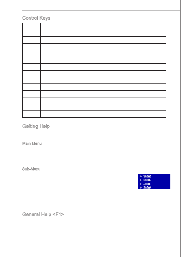
Control Keys
<↑> Move to the prevous tem
<↓> Move to the next tem
<←> Move to the tem n the left hand
<→> Move to the tem n the rght hand
<Enter> Select the tem
<Esc> Jumps to the Ext menu or returns to the man menu from a submenu
<+/PU> Increase the numerc value or make changes
<-/PD> Decrease the numerc value or make changes
<F1> General Help
<F4> Enter the CPU Spec. menu, and read the CPU nformaton
<F5> Enter the Memory-Z menu, and read the memory nformaton
<F6> Load Optmzed Defaults
<F8> Load Fal-Safe Defaults
<F10> Save all the CMOS changes and ext
Gettng Help
After enterng the Setup menu, the rst menu you wll see s the Man Menu.
Man Menu
The man menu lsts the setup functons you can make changes to. You can use the
arrow keys ( ↑↓ ) to select the tem. The on-lne descrpton of the hghlghted setup
functon s dsplayed at the bottom of the screen.
Sub-Menu
If you nd a rght ponter symbol (as shown n the rght vew) ap-
pears to the left of certan elds that means a sub-menu can be
launched from ths eld. A sub-menu contans addtonal optons
for a eld parameter. You can use arrow keys ( ↑↓ ) to hghlght
the eld and press <Enter> to call up the sub-menu. Then you can use the control keys
to enter values and move from eld to eld wthn a sub-menu. If you want to return to
the man menu, just press the <Esc >.
General Help <F1>
The BIOS setup program provdes a General Help screen. You can call up ths screen
from any menu by smply pressng <F1>. The Help screen lsts the approprate keys to
use and the possble selectons for the hghlghted tem. Press <Esc> to ext the Help
3-4
BIOS Setup
▍MS-7593
BIOS Setup
▍MS-7593
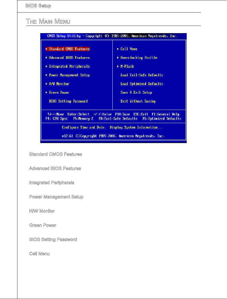
the Main Menu
Standard CMOS Features
Use ths menu for basc system conguratons, such as tme, date etc.
Advanced BIOS Features
Use ths menu to setup the tems of the BIOS specal enhanced features.
Integrated Perpherals
Use ths menu to specfy your settngs for ntegrated perpherals.
Power Management Setup
Use ths menu to specfy your settngs for power management.
H/W Montor
Ths entry shows your PC health status.
Green Power
Use ths menu to specfy the power phase.
BIOS Settng Password
Use ths menu to set the password for BIOS.
Cell Menu
Use ths menu to specfy your settngs for frequency/voltage control and overclockng.
▶
▶
▶
▶
▶
▶
▶
▶
BIOS Setup
▍MS-7593
3-5
BIOS Setup
▍MS-7593
Overclockng Prole
Use ths menu to save/ load your settngs to/ from CMOS for BIOS.
M-Flash
Use ths menu to read/ ash the BIOS from storage drve (FAT/ FAT32 format only).
Load Fal-Safe Defaults
Use ths menu to load the default values set by the BIOS vendor for stable system
performance.
Load Optmzed Defaults
Use ths menu to load the default values set by the manboard manufacturer speccally
for optmal performance of the manboard.
Save & Ext Setup
Save changes to CMOS and ext setup.
Ext Wthout Savng
Abandon all changes and ext setup.
▶
▶
▶
▶
▶
▶
3-6
BIOS Setup
▍MS-7593
BIOS Setup
▍MS-7593
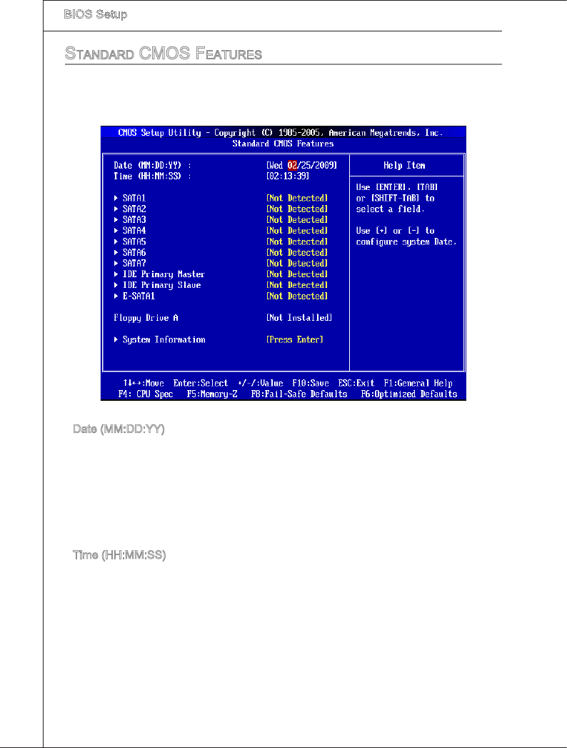
Standard cMoS featureS
The tems n Standard CMOS Features Menu nclude some basc setup tems. Use the
arrow keys to hghlght the tem and then use the <PgUp> or <PgDn> keys to select the
value you want n each tem.
Date (MM:DD:YY)
Ths allows you to set the system to the date that you want (usually the current date).
The format s <day><month> <date> <year>.
[day] Day of the week, from Sun to Sat, determned by BIOS. Read-
only.
[month] The month from Jan. through Dec.
[date] The date from 1 to 31 can be keyed by numerc functon keys.
[year] The year can be adjusted by users.
Tme (HH:MM:SS)
Ths allows you to set the system tme that you want (usually the current tme). The tme
format s <hour> <mnute> <second>.
▶
▶
BIOS Setup
▍MS-7593
3-7
BIOS Setup
▍MS-7593
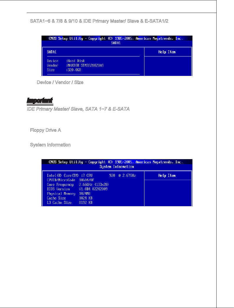
SATA1~6 & 7/8 & 9/10 & IDE Prmary Master/ Slave & E-SATA1/2
Press <Enter> to enter the sub-menu, and the followng screen appears.
Devce / Vendor / Sze
It wll show the devce nformaton that you connected to the SATA connector.
Important
IDE Prmary Master/ Slave, SATA 1~7 & E-SATA are appearng when you connect the
HD devces to the IDE/ SATA/ E-SATA connectors on the manboard.
Floppy Drve A
Ths tem allows you to set the type of oppy drves nstalled.
System Informaton
Press <Enter> to enter the sub-menu, and the followng screen appears.
Ths sub-menu shows the CPU nformaton, BIOS verson and memory status of your
system (read only).
▶
▶
▶
▶
3-8
BIOS Setup
▍MS-7593
BIOS Setup
▍MS-7593
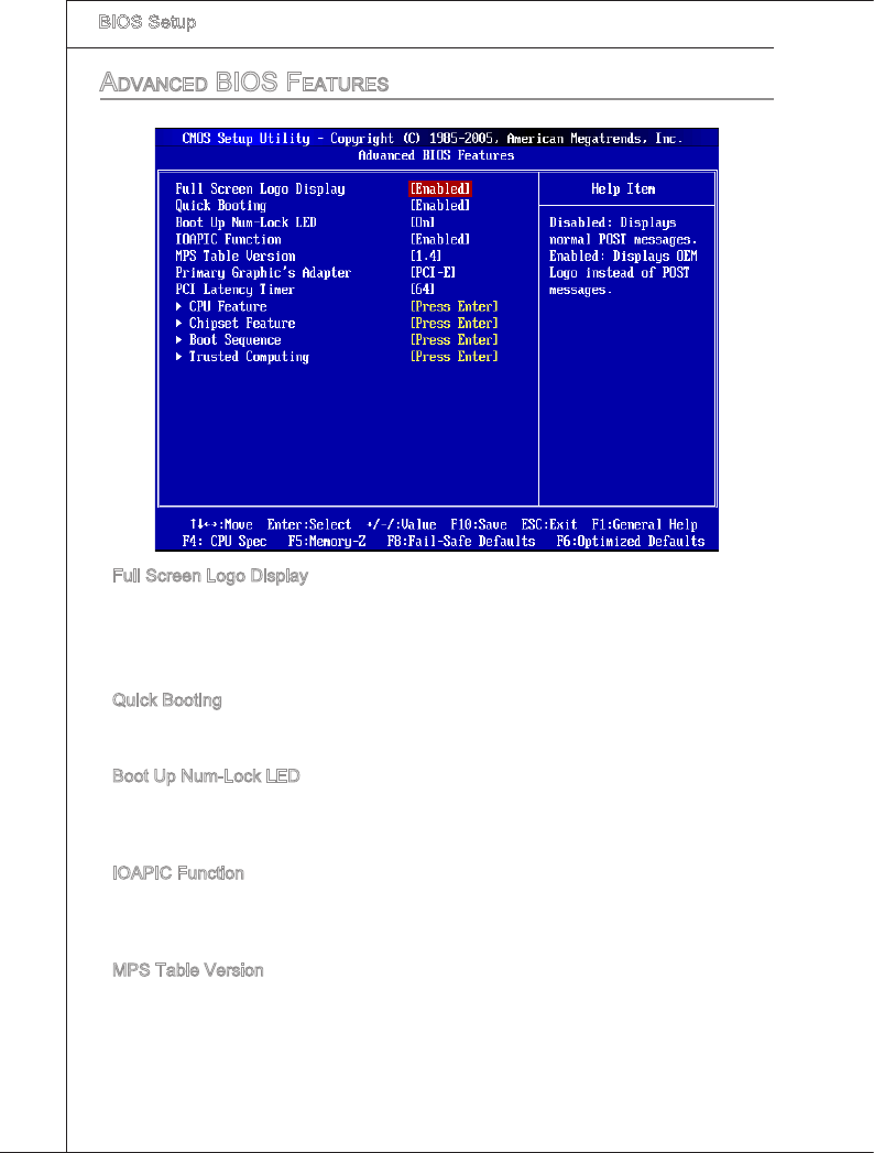
advanced bioS featureS
Full Screen Logo Dsplay
Ths tem enables ths system to show the company logo on the boot-up screen. Set-
tngs are:
[Enabled] Shows a stll mage (logo) on the full screen at boot.
[Dsabled] Shows the POST messages at boot.
Quck Bootng
Settng the tem to [Enabled] allows the system to boot wthn 10 seconds snce t wll
skp some check tems.
Boot Up Num-Lock LED
Ths settng s to set the Num Lock status when the system s powered on. Settng to
[On] wll turn on the Num Lock key when the system s powered on. Settng to [O] wll
allow users to use the arrow keys on the numerc keypad.
IOAPIC Functon
Ths eld s used to enable or dsable the APIC (Advanced Programmable Interrupt
Controller). Due to complance wth PC2001 desgn gude, the system s able to run n
APIC mode. Enablng APIC mode wll expand avalable IRQ resources for the system.
MPS Table Verson
Ths eld allows you to select whch MPS (Mult-Processor Speccaton) verson to be
used for the operatng system. You need to select the MPS verson supported by your
operatng system. To nd out whch verson to use, consult the vendor of your operatng
system.
▶
▶
▶
▶
▶
BIOS Setup
▍MS-7593
3-9
BIOS Setup
▍MS-7593
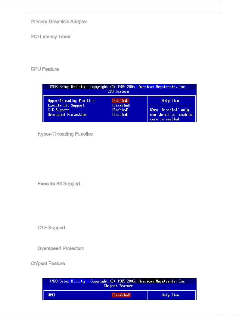
Prmary Graphc’s Adapter
Ths settng speces whch graphc card s your prmary graphcs adapter.
PCI Latency Tmer
Ths tem controls how long each PCI devce can hold the bus before another takes
over. When set to hgher values, every PCI devce can conduct transactons for a longer
tme and thus mprove the eectve PCI bandwdth. For better PCI performance, you
should set the tem to hgher values.
CPU Feature
Press <Enter> to enter the sub-menu and the followng screen appears:
Hyper-Threadng Functon
The processor uses Hyper-Threadng technology to ncrease transacton rates and
reduces end-user response tmes. The technology treats the two cores nsde the
processor as two logcal processors that can execute nstructons smultaneously. In
ths way, the system performance s hghly mproved. If you dsable the functon, the
processor wll use only one core to execute the nstructons. Please dsable ths tem
f your operatng system doesn’t support HT Functon, or unrelablty and nstablty
may occur.
Execute Bt Support
Intel’s Execute Dsable Bt functonalty can prevent certan classes of malcous
“buer overow” attacks when combned wth a supportng operatng system. Ths
functonalty allows the processor to classfy areas n memory by where applcaton
code can execute and where t cannot. When a malcous worm attempts to nsert
code n the buer, the processor dsables code executon, preventng damage or
worm propagaton.
C1E Support
To enable ths tem to read the CPU power consumpton whle dle. Not all proces-
sors support Enhanced Halt state (C1E).
Overspeed Protecton
Ths tem s used to enable/ dsable Overspeed Protecton.
Chpset Feature
Press <Enter> to enter the sub-menu and the followng screen appears:
▶
▶
▶
▶
▶
▶
▶
▶
3-10
BIOS Setup
▍MS-7593
BIOS Setup
▍MS-7593
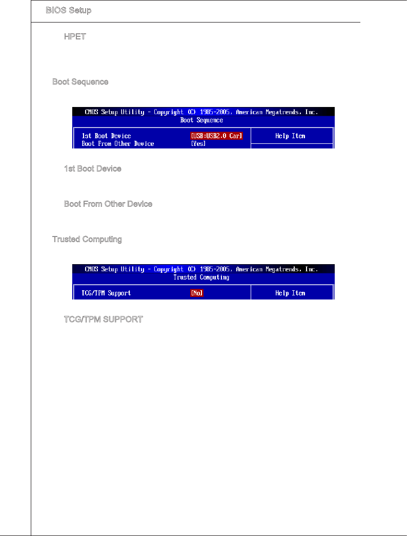
HPET
The HPET (Hgh Precson Event Tmers) s a component that s part of the chpset.
You can to enable t, and wll provde you wth the means to get to t va the varous
ACPI methods.
Boot Sequence
Press <Enter> to enter the sub-menu and the followng screen appears:
1st Boot Devce
Ths tem allows you to set the rst boot devce where BIOS attempts to load the dsk
operatng system.
Boot From Other Devce
Settng the opton to [Yes] allows the system to try to boot from other devce, f the
system fals to boot from 1st boot devce.
Trusted Computng
Press <Enter> to enter the sub-menu and the followng screen appears:
TCG/TPM SUPPORT
Settng the opton to [Yes] enables TPM (Trusted Platform Module) to the system.
▶
▶
▶
▶
▶
▶
BIOS Setup
▍MS-7593
3-11
BIOS Setup
▍MS-7593
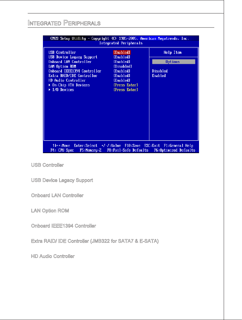
integrated peripheraLS
USB Controller
Ths settng allows you to enable/dsable the onboard USB controller.
USB Devce Legacy Support
Select [Enabled] f you need to use a USB-nterfaced devce n the operatng system.
Onboard LAN Controller
Ths settng allows you to enable/dsable the onboard LAN controller.
LAN Opton ROM
Ths tem s used to decde whether to nvoke the Boot ROM of the onboard LAN.
Onboard IEEE1394 Controller
Ths tem allows you to enable/dsable the onboard IEEE1394 controller.
Extra RAID/ IDE Controller (JMB322 for SATA7 & E-SATA)
Ths tem allows you to enable/dsable the onboard extra RAID/ IDE controller.
HD Audo Controller
Ths settng s used to enable/dsable the onboard audo controller.
▶
▶
▶
▶
▶
▶
▶
3-12
BIOS Setup
▍MS-7593
BIOS Setup
▍MS-7593
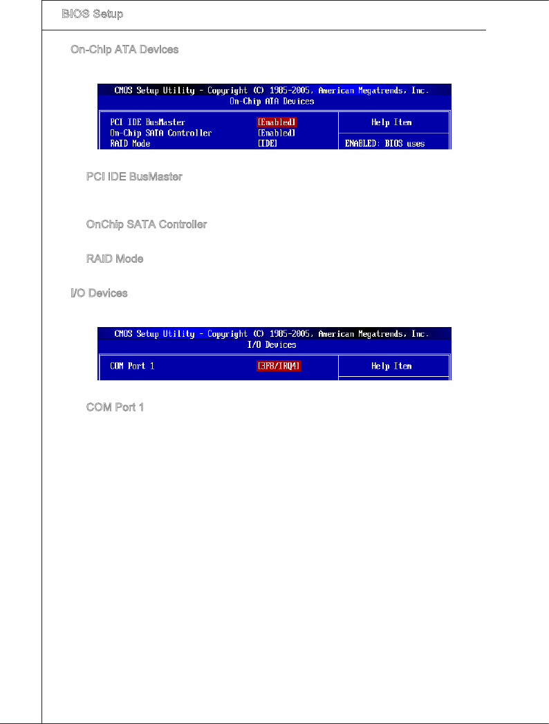
On-Chp ATA Devces
Press <Enter> to enter the sub-menu and the followng screen appears:
PCI IDE BusMaster
Ths tem allows you to enable/ dsable BIOS to used PCI busmasterng for readng/
wrtng to IDE drves.
OnChp SATA Controller
Ths tem allows users to enable or dsable the SATA controller.
RAID Mode
Ths tem s used to select mode for SATA connectors.
I/O Devces
Press <Enter> to enter the sub-menu and the followng screen appears:
COM Port 1
Select an address and correspondng nterrupt for the seral port.
▶
▶
▶
▶
▶
▶
BIOS Setup
▍MS-7593
3-13
BIOS Setup
▍MS-7593
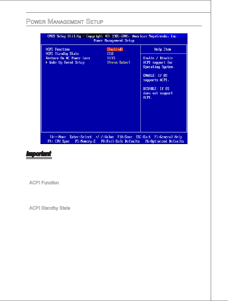
power ManageMent Setup
Important
S3-related functons descrbed n ths secton are avalable only when the BIOS sup-
ports S3 sleep mode.
ACPI Functon
Ths tem s to actvate the ACPI (Advanced Conguraton and Power Management
Interface) Functon. If your operatng system s ACPI-aware, such as Wndows 98SE/
2000/ ME/ XP, select [Enabled].
ACPI Standby State
Ths tem speces the power savng modes for ACPI functon. If your operatng system
supports ACPI, such as Wndows 2000/ XP, you can choose to enter the Standby mode
n S1(POS) or S3(STR) fashon through the settng of ths eld. Settngs are:
[S1] The S1 sleep mode s a low power state. In ths state, no system
context s lost (CPU or chpset) and hardware mantans all sys-
tem’s context.
[S3] The S3 sleep mode s a lower power state where the n formaton of
system conguraton and open applcatons/les s saved to man
memory that remans powered whle most other hardware compo-
nents turn o to save energy. The nformaton stored n memory wll
be used to restore the system when a “wake up” event occurs.
▶
▶
3-14
BIOS Setup
▍MS-7593
BIOS Setup
▍MS-7593
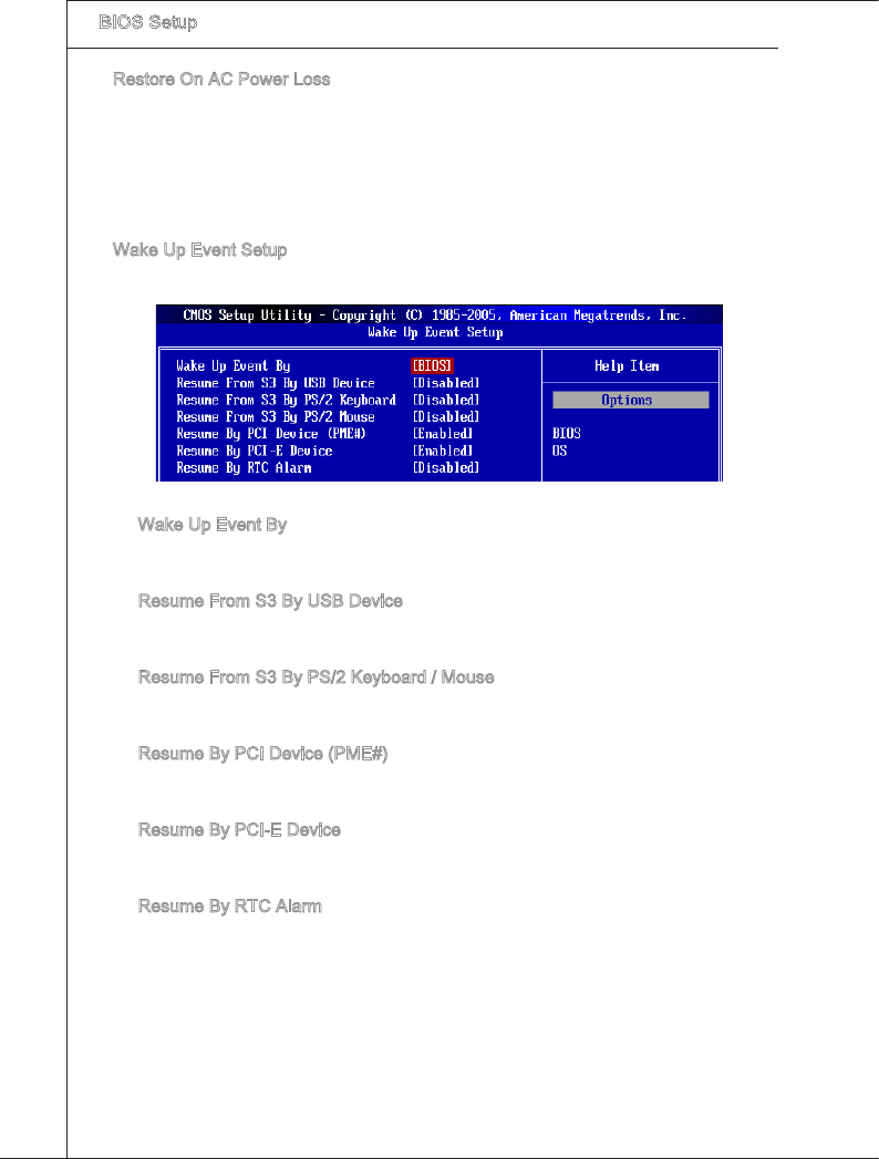
Restore On AC Power Loss
Ths tem speces whether your system wll reboot after a power falure or nterrupt
occurs. Settngs are:
[O] Always leaves the computer n the power o state.
[On] Always leaves the computer n the power on state.
[Last State] Restore the system to the status before power falure or nterrupt
occurred.
Wake Up Event Setup
Press <Enter> and the followng sub-menu appears.
Wake Up Event By
Settng to [BIOS] actvates the followng elds, and use the followng elds to set the
wake up events. Settng to [OS], the wake up events wll be dened by OS.
Resume From S3 By USB Devce
The tem allows the actvty of the USB devce to wake up the system from S3 (Sus-
pend to RAM) sleep state.
Resume From S3 By PS/2 Keyboard / Mouse
These tems determne whether the system wll be awakened from what power sav-
ng modes when nput sgnal of the PS/2 keyboard/ mouse s detected.
Resume By PCI Devce (PME#)
When set to [Enabled], the feature allows your system to be awakened from the
power savng modes through any event on PME (Power Management Event).
Resume By PCI-E Devce
When set to [Enabled], the feature allows your system to be awakened from the
power savng modes through any event on PCIE devce.
Resume By RTC Alarm
The eld s used to enable or dsable the feature of bootng up the system on a
scheduled tme/date.
▶
▶
▶
▶
▶
▶
▶
▶
BIOS Setup
▍MS-7593
3-15
BIOS Setup
▍MS-7593
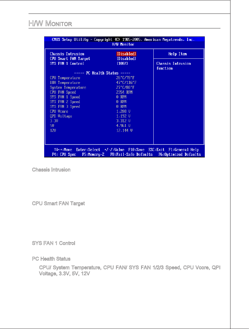
h/w Monitor
Chasss Intruson
The eld enables or dsables the feature of recordng the chasss ntruson status and
ssung a warnng message f the chasss s once opened. To clear the warnng mes-
sage, set the eld to [Reset]. The settng of the eld wll automatcally return to [Enabled]
later.
CPU Smart FAN Target
The manboard provdes the Smart Fan functon whch can control the CPU fan speed
automatcally dependng on the current temperature to keep t wth n a specc range.
You can enable a fan target value here. If the current CPU fan temperature reaches to
the target value, the smart fan functon wll be actvated. It provdes several sectons to
speed up for coolng down automatcally.
SYS FAN 1 Control
Ths tem allows users to select how percentage of speed for the SYSFAN1.
PC Health Status
CPU/ System Temperature, CPU FAN/ SYS FAN 1/2/3 Speed, CPU Vcore, QPI
Voltage, 3.3V, 5V, 12V
These tems dsplay the current status of all of the montored hardware devces/com-
ponents such as CPU voltage, temperatures and all fans’ speeds.
▶
▶
▶
▶
▶
3-16
BIOS Setup
▍MS-7593
BIOS Setup
▍MS-7593
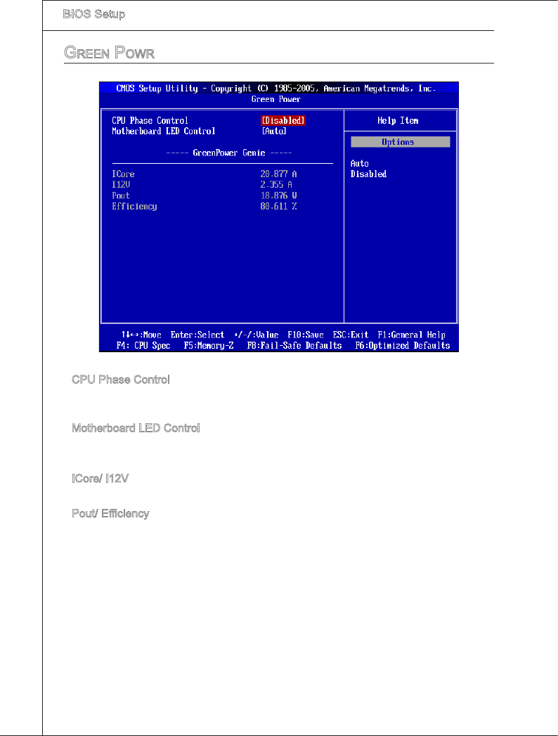
green powr
CPU Phase Control
When set to [Auto], the hardware wll auto adjust the CPU power phase accordng to the
loadng of CPU to reach the best power savng functon.
Motherboard LED Control
Ths tem s used to enable/ dsable the power phase LEDs of the motherboard.
----- GreenPower Gene-----
ICore/ I12V
These tems show the amperage of Core/ 12V. Read only.
Pout/ Ecency
These tems show the power consumpton & ecency of the system. Read only.
▶
▶
▶
▶
BIOS Setup
▍MS-7593
3-17
BIOS Setup
▍MS-7593
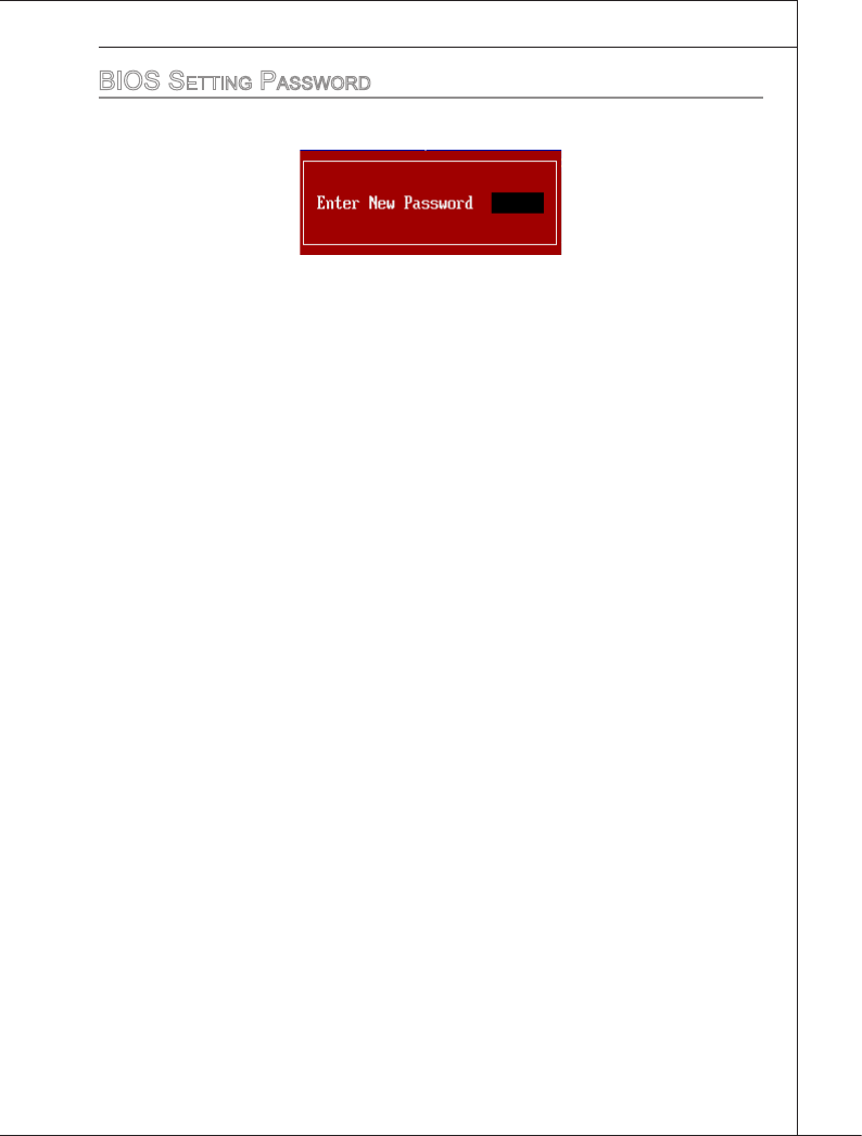
bioS Setting paSSword
When you select ths functon, a message as below wll appear on the screen:
Type the password, up to sx characters n length, and press <Enter>. The password
typed now wll replace any prevously set password from CMOS memory. You wll be
prompted to conrm the password. Retype the password and press <Enter>. You may
also press <Esc> to abort the selecton and not enter a password.
To clear a set password, just press <Enter> when you are prompted to enter the pass-
word. A message wll show up conrmng the password wll be dsabled. Once the
password s dsabled, the system wll boot and you can enter Setup wthout enterng
any password.
When a password has been set, you wll be prompted to enter t every tme you try to
enter Setup. Ths prevents an unauthorzed person from changng any part of your
system conguraton.
3-18
BIOS Setup
▍MS-7593
BIOS Setup
▍MS-7593
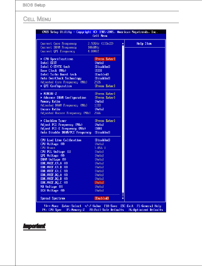
ceLL Menu
Important
Change these settngs only f you are famlar wth the chpset.
BIOS Setup
▍MS-7593
3-19
BIOS Setup
▍MS-7593
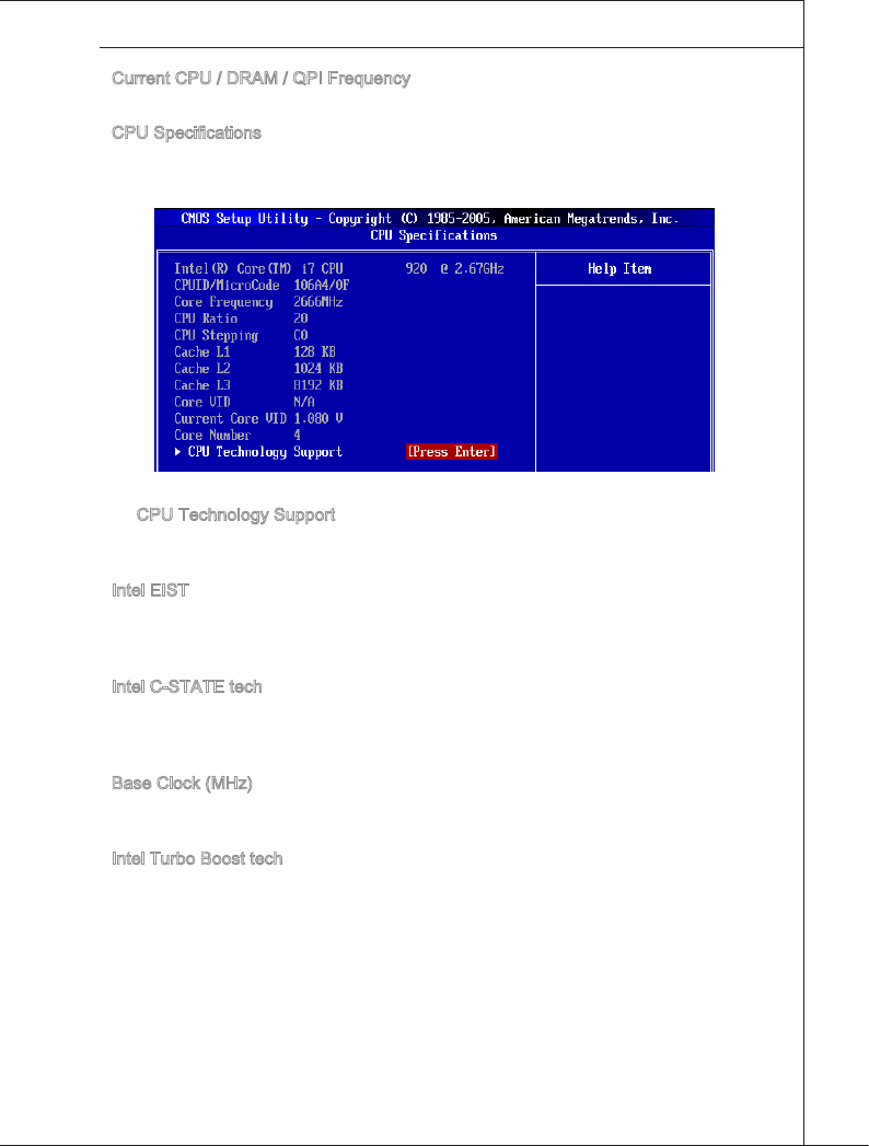
Current CPU / DRAM / QPI Frequency
These tems show the current frequences of CPU, Memory and QPI. Read-only.
CPU Speccatons
Press <Enter> to enter the sub-menu and the followng screen appears. Ths submenu
shows the nformaton of nstalled CPU.
CPU Technology Support
Press <Enter> to enter the sub-menu. Ths sub-menu shows the technologes that
the nstalled CPU supported.
Intel EIST
The Enhanced Intel SpeedStep technology allows you to set the performance level of
the mcroprocessor whether the computer s runnng on battery or AC power. Ths eld
wll appear after you nstalled the CPU whch support speedstep technology.
Intel C-STATE tech
C-state s a power management state that sgncantly reduces the power of the proces-
sor durng dle. Ths eld wll appear after you nstalled the CPU whch support c-state
technology.
Base Clock (MHz)
Ths tem allows you to set the CPU Base clock (n MHz). You may overclock the CPU
by adjustng ths value. Please note the overclockng behavor s not guaranteed.
Intel Turbo Boost tech
Ths tem wll appear when you nstall a CPU wth Intel Turbo Boost technology. Ths
tem s used to enable/ dsable Intel Turbo Boost technology. It can scale processor
frequency hgher dynamcally when applcatons demand more performance and TDP
headroom exsts. It also can delver seamless power scalablty (Dynamcally scale up,
Speed-Step Down). It s the Intel newly technology wthn 7 CPU.
▶
▶
▶
▶
▶
▶
▶
3-20
BIOS Setup
▍MS-7593
BIOS Setup
▍MS-7593
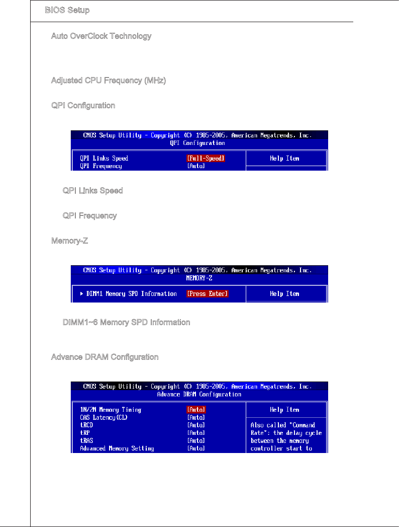
Auto OverClock Technology
Settng ths tem to [Max FSB] allows the system to detect the FSB lmtaton for over-
clockng automatcally. If overclockng fals, you can try the lower FSB clock for over-
clockng successfully.
Adjusted CPU Frequency (MHz)
It shows the adjusted CPU frequency (Base clock x Rato). Read-only.
QPI Conguraton
Press <Enter> to enter the sub-menu and the followng screen appears.
QPI Lnks Speed
Ths tem allows you to select the QPI lnks speed type.
QPI Frequency
Ths tem allows you to select the QPI frequency.
Memory-Z
Press <Enter> to enter the sub-menu and the followng screen appears.
DIMM1~6 Memory SPD Informaton
Press <Enter> to enter the sub-menu. The sub-menu dsplays the nformatons of
nstalled memory.
Advance DRAM Conguraton
Press <Enter> to enter the sub-menu and the followng screen appears.
▶
▶
▶
▶
▶
▶
▶
▶
BIOS Setup
▍MS-7593
3-21
BIOS Setup
▍MS-7593
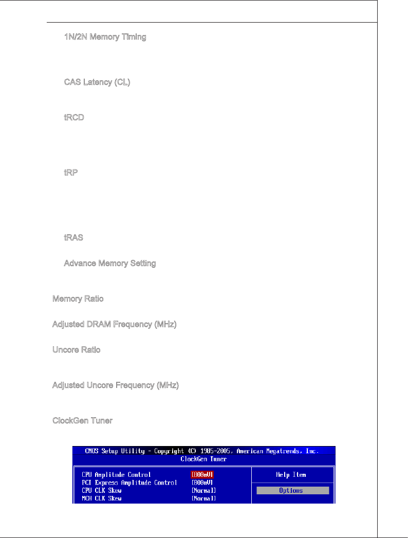
1N/2N Memory Tmng
Ths tem controls the SDRAM command rate. Select [1N] makes SDRAM sgnal
controller to run at 1N (N=clock cycles) rate. Selectng [2N] makes SDRAM sgnal
controller run at 2N rate.
CAS Latency (CL)
Ths controls the CAS latency, whch determnes the tmng delay (n clock cycles)
before SDRAM starts a read command after recevng t.
tRCD
When DRAM s refreshed, both rows and columns are addressed separately. Ths
setup tem allows you to determne the tmng of the transton from RAS (row ad-
dress strobe) to CAS (column address strobe). The less the clock cycles, the faster
the DRAM performance.
tRP
Ths settng controls the number of cycles for Row Address Strobe (RAS) to be
allowed to precharge. If nsucent tme s allowed for the RAS to accumulate ts
charge before DRAM refresh, refresh may be ncomplete and DRAM may fal to
retan data. Ths tem apples only when synchronous DRAM s nstalled n the sys-
tem.
tRAS
Ths settng determnes the tme RAS takes to read from and wrte to memory cell.
Advance Memory Settng
Settng to [Auto] enables the advance memory tmng automatcally to be determned
by BIOS. Settng to [Manual] allows you to set advanced memory tmngs.
Memory Rato
Ths tem allows you to set the memory multpler.
Adjusted DRAM Frequency (MHz)
It shows the adjusted DDR Memory frequency. Read-only.
Uncore Rato
Ths tem allows you to set the uncore (clock speed of the L3 cache and memory con-
troller) multpler.
Adjusted Uncore Frequency (MHz)
It shows the adjusted uncore frequency (uncore rato x base clock, the clock speed of
the L3 cache and memory controller). Read-only.
ClockGen Tuner
Press <Enter> to enter the sub-menu and the followng screen appears.
▶
▶
▶
▶
▶
▶
▶
▶
▶
▶
▶
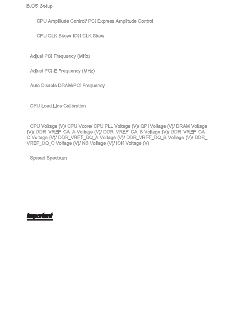
3-22
BIOS Setup
▍MS-7593
BIOS Setup
▍MS-7593
CPU Ampltude Control/ PCI Express Ampltude Control
These tems are used to select the CPU/ PCI Express clock ampltude.
CPU CLK Skew/ IOH CLK Skew
These tems are used to select the CPU/ IOH chpset clock skew. They can help
CPU to reach the hgher overclockng performace.
Adjust PCI Frequency (MHz)
Ths eld allows you to select the PCI frequency (n MHz).
Adjust PCI-E Frequency (MHz)
Ths eld allows you to select the PCIE frequency (n MHz).
Auto Dsable DRAM/PCI Frequency
When set to [Enabled], the system wll remove (turn o) clocks from empty DIMM and
PCI slots to mnmze the electromagnetc nterference (EMI).
CPU Load Lne Calbraton
When set to [Enabled], system wll automatcally x the vcore droop ssue of CPU, and
the CPU can receve stable voltage n overclockng.
CPU Voltage (V)/ CPU Vcore/ CPU PLL Voltage (V)/ QPI Voltage (V)/ DRAM Voltage
(V)/ DDR_VREF_CA_A Voltage (V)/ DDR_VREF_CA_B Voltage (V)/ DDR_VREF_CA_
C Voltage (V)/ DDR_VREF_DQ_A Voltage (V)/ DDR_VREF_DQ_B Voltage (V)/ DDR_
VREF_DQ_C Voltage (V)/ NB Voltage (V)/ ICH Voltage (V)
These tems are used to adjust the voltage of CPU, Memory and chpset.
Spread Spectrum
When the manboard’s clock generator pulses, the extreme values (spkes) of the pulses
create EMI (Electromagnetc Interference). The Spread Spectrum functon reduces the
EMI generated by modulatng the pulses so that the spkes of the pulses are reduced to
atter curves. If you do not have any EMI problem, leave the settng at Dsabled for opt-
mal system stablty and performance. But f you are plagued by EMI, set to Enabled for
EMI reducton. Remember to dsable Spread Spectrum f you are overclockng because
even a slght jtter can ntroduce a temporary boost n clock speed whch may just cause
your overclocked processor to lock up.
Important
If you do not have any EMI problem, leave the settng at [Dsabled] for optmal system
stablty and performance. But f you are plagued by EMI, select the value of Spread
Spectrum for EMI reducton.
The greater the Spread Spectrum value s, the greater the EMI s reduced, and the
system wll become less stable. For the most sutable Spread Spectrum value, please
consult your local EMI regulaton.
Remember to dsable Spread Spectrum f you are overclockng because even a slght
jtter can ntroduce a temporary boost n clock speed whch may just cause your over-
clocked processor to lock up.
▶
▶
▶
▶
▶
▶
▶
▶
•
•
•
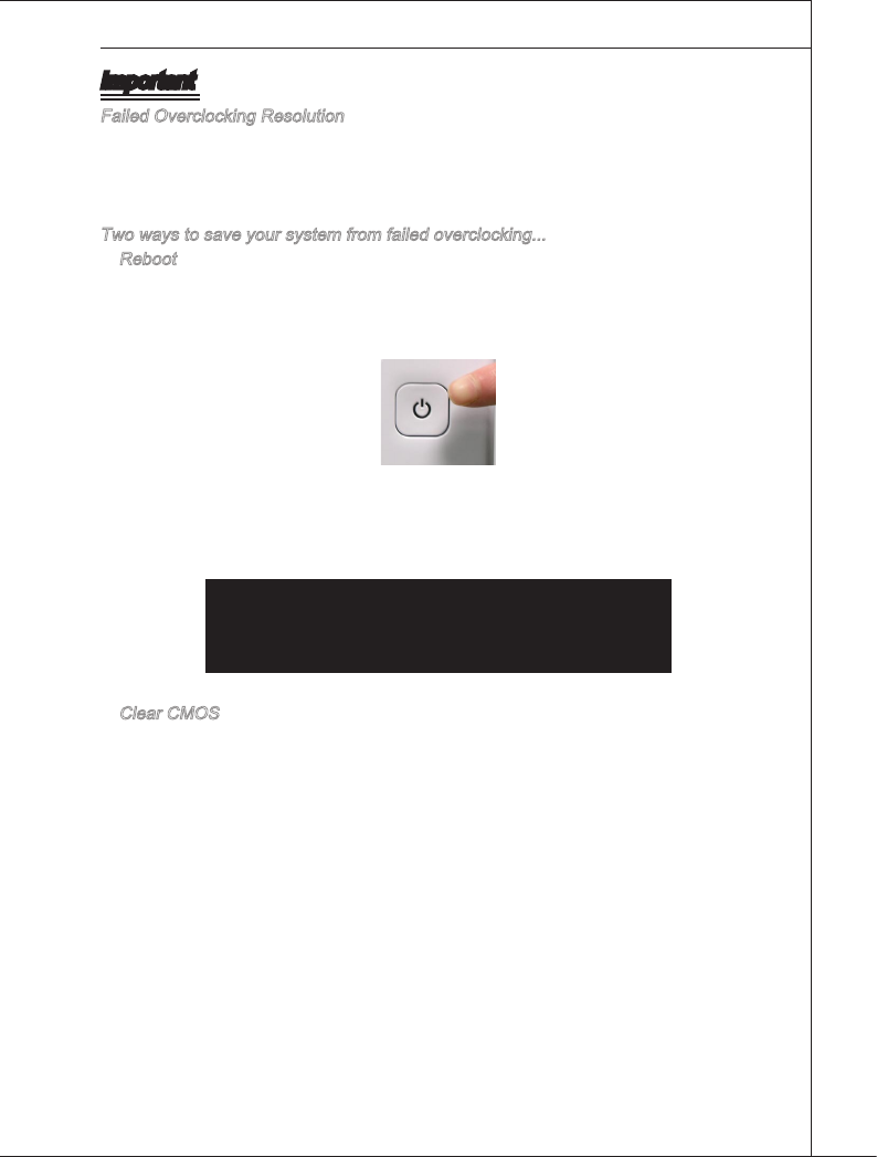
BIOS Setup
▍MS-7593
3-23
BIOS Setup
▍MS-7593
Important
Faled Overclockng Resoluton
Ths motherboard supports overclockng greatly. However, please make sure your pe-
rpherals and components are bearable for some specal settngs. Any operaton that
exceeds product speccaton s not recommended. Any rsk or damge resultng from
mproper operaton wll not be under our product warranty.
Two ways to save your system from faled overclockng...
Reboot
Press the Power button to reboot the system three tmes. Please note that, to avod
electrc current to aect other devces or components, we suggest an nterval of more
than 10 seconds among the reboot actons.
At the fourth reboot, BIOS wll determne that the prevous overclockng s faled and
restore the default settngs automatcally. Please press any key to boot the system
normally when the followng message appears on screen.
Warnng !!! The prevous overclockng had faled,
and system wll restore ts defaults settng,
Press any key to contnue.......
Clear CMOS
Please refer to “Chapter 2” for more nformaton about how to clear CMOS data.
•
•
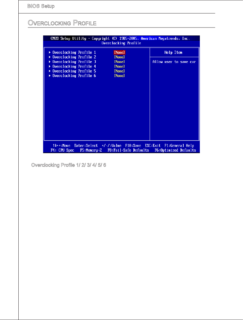
3-24
BIOS Setup
▍MS-7593
BIOS Setup
▍MS-7593
overcLocking profiLe
Overclockng Prole 1/ 2/ 3/ 4/ 5/ 6
These tems are used to save the currect settngs to selected prole, and they are also
used to load the settngs from the selected prole.
▶
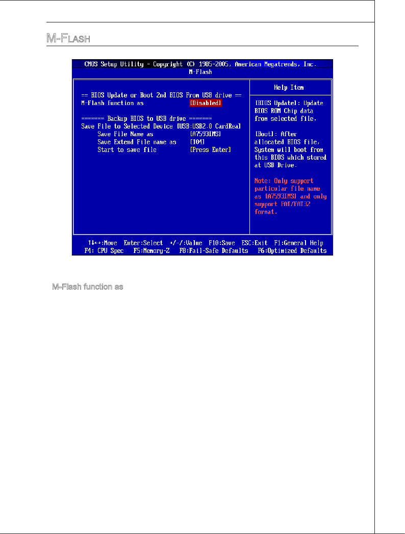
BIOS Setup
▍MS-7593
3-25
BIOS Setup
▍MS-7593
M-fLaSh
== BIOS Update or Boot 2nd BIOS From USB drve==
M-Flash functon as
M-Flash functon allows you to ash BIOS from USB drve/ storage drve (FAT/ FAT32
format only), or allows the system to boot from the BIOS le nsde USB drve (FAT/
FAT32 format only).
[Dsabled] Dsable M-Flash functon.
[BIOS Update] Flash BIOS va the USB/ Storage drve drectly. Update BIOS ROM
chp data from selected le, whch was be download from ocal
webste and must be saved n the root drectory of the USB/ Stor-
age drve. It only supports partcular le name,
whch s the ocal BIOS le name from us.
[Boot] After allocated partcular BIOS le, system wll boot from ths BIOS
le whch saved n the root drectory of USB drve. System wll skp
MB ROM chp data and boot wth ths partcular BIOS nsde USB
drve. Note: ths opton s for USB drve only.
▶
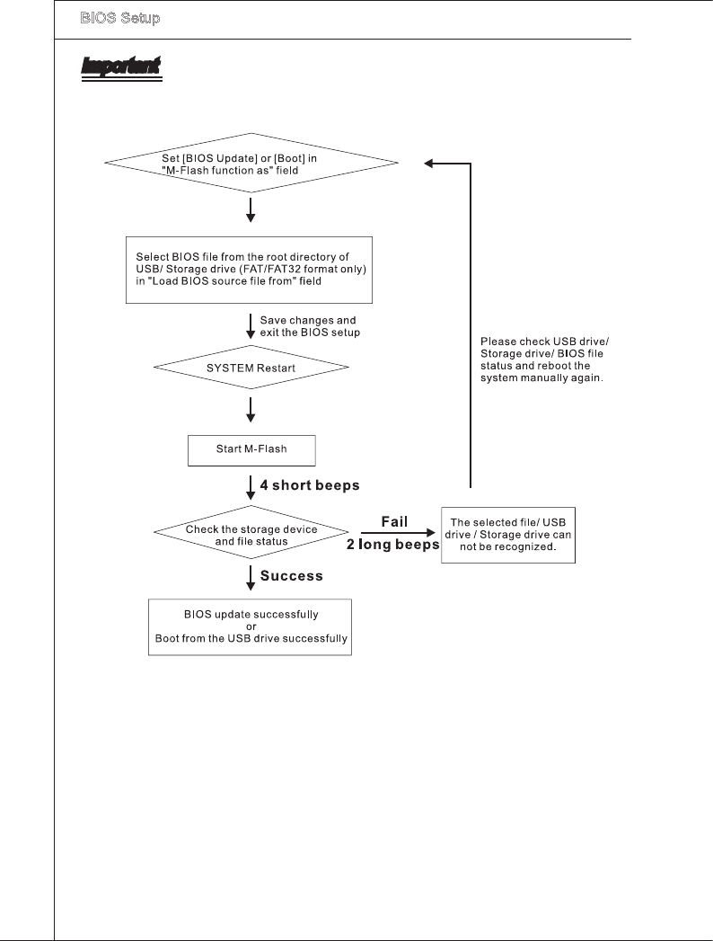
3-26
BIOS Setup
▍MS-7593
BIOS Setup
▍MS-7593
Important
Please refer to the block dagram below about the M-Flash functon.
Due to the specal desgn of some graphcs cards wll cause dark screen durng M-
ash operaton, and you may refer the beeps from the system to conrm the current
M-ash process.
•
•
BIOS Setup
▍MS-7593
3-27
BIOS Setup
▍MS-7593
Load BIOS source le from
When the M-Flash functon as sets to [Boot] or [BIOS Update], ths tem s selectable.
Use ths tem to select partcular BIOS le from the USB/ Storage (FAT/32 format
only) drve.
== Backup BIOS to USB drve ==
The followng elds are used to read the onboard BIOS ROM data, and save t to USB
drve/ storage drve.
Save Fle to Selected Devce
Please setup a specc folder n specc USB drve/ storage drve to save BIOS le from
BIOS ROM chp data. Note: t only supports FAT/ FAT32 le system drve.
Save Fle Name as
Please setup a specc name for the BIOS le, whch wll be saved nto the USB drve/
storage drve. Note: we suggest you usng the ocal name as the default name.
Save Extend Fle name as
Please setup a specc extend name for the BIOS le, whch wll be saved nto the USB
drve/ storage drve. Note: we suggest you usng [ROM] as default name.
Start to save le
Press “Enter” and select “OK” the system wll stare to save the onboard ROM chp data
to the selected USB drve/ storage drve.
▶
▶
▶
▶
▶
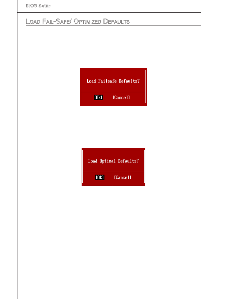
3-28
BIOS Setup
▍MS-7593
Load faiL-Safe/ optiMized defauLtS
The two optons on the man menu allow users to restore all of the BIOS settngs to the
default Fal-Safe or Optmzed values. The Optmzed Defaults are the default values set
by the manboard manufacturer speccally for optmal performance of the manboard.
The Fal-Safe Defaults are the default values set by the BIOS vendor for stable system
performance.
When you select Load Fal-Safe Defaults, a message as below appears:
Selectng Ok and pressng Enter loads the BIOS default values for the most stable,
mnmal system performance.
When you select Load Optmzed Defaults, a message as below appears:
Selectng Ok and pressng Enter loads the default factory settngs for optmal system
performance.

A-1
The Realtek audo provdes 10-channel DAC that smul-
taneously supports 7.1 sound playback and 2 channels
of ndependent stereo sound output (multple streamng)
through the Front-Out-Left and Front-Out-Rght chan-
nels.
Appendx A
Realtek Audo
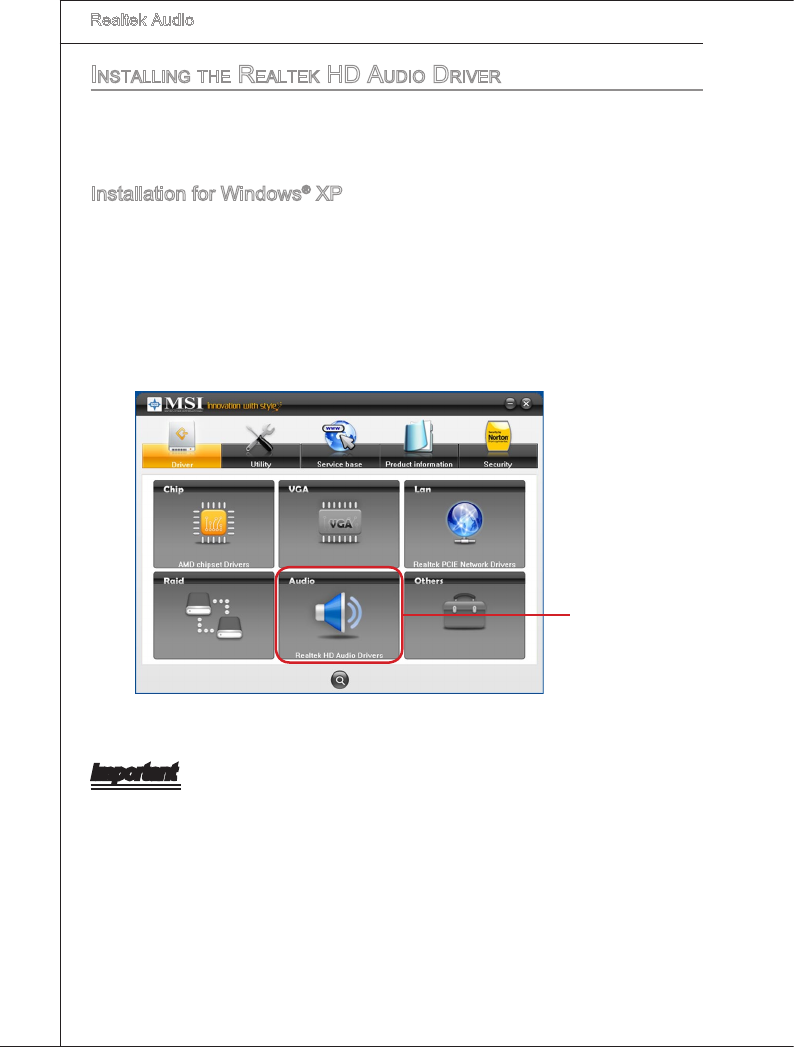
A-2
Realtek Audo
▍
inStaLLing the reaLtek hd audio driver
You need to nstall the HD audo drver for Realtek audo codec to functon properly
before you can get access to 2-, 4-, 6-, 8- channel or 7.1+2 channel audo operatons.
Follow the procedures descrbed below to nstall the drvers for derent operatng sys-
tems.
Installaton for Wndows® XP
For Wndows® XP, you must nstall Wndows® XP Servce Pack3 or later before nstallng
the drver.
The followng llustratons are based on Wndows® XP envronment and could look
slghtly derent f you nstall the drvers n derent operatng systems.
Insert the applcaton DVD nto the DVD-ROM drve. The setup screen wll automat-
cally appear.
Clck Realtek HD Audo Drvers button.
1.
2.
Important
The HD Audo Conguraton software utlty s under contnuous update to enhance au-
do applcatons. Hence, the program screens shown here n ths secton may be slghtly
derent from the latest software utlty and shall be held for reference only.
Clck here
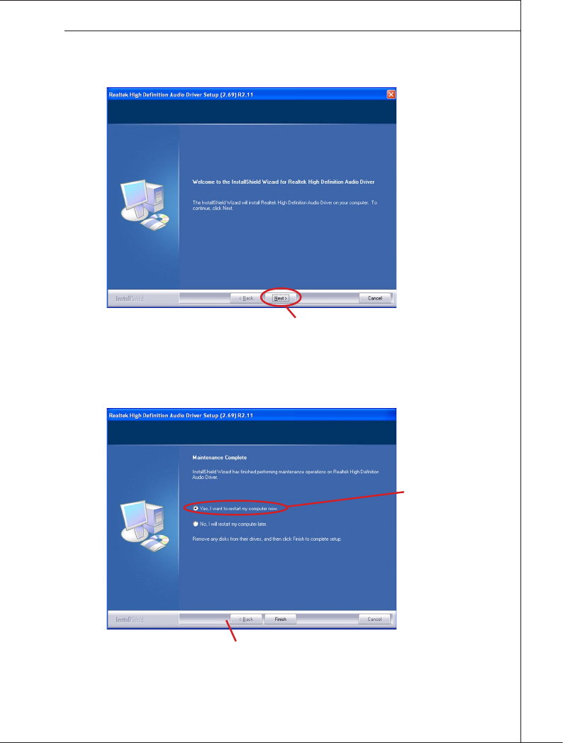
A-3
MS-7593
Clck Next to nstall the Realtek Hgh Denton Audo Drver.3.
Clck Fnsh to restart the system.
4.
Clck here
Clck here
Select ths opton
Clck here
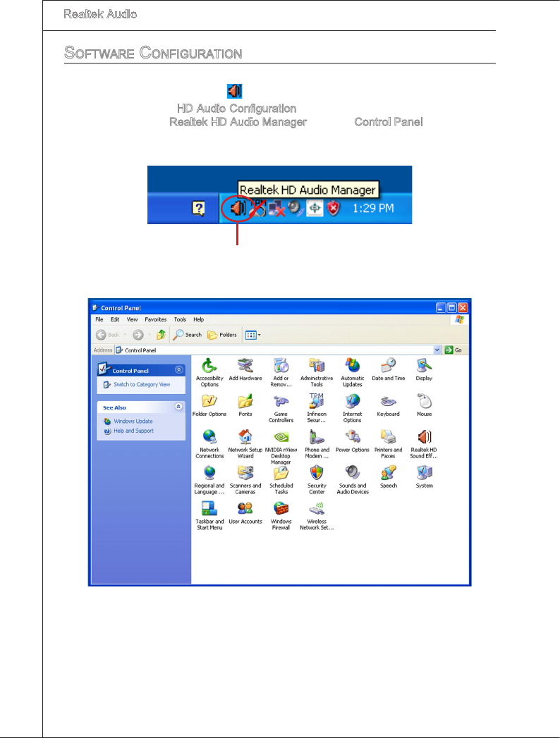
A-4
Realtek Audo
▍
Software configuration
After nstallng the audo drver, you are able to use the 2-, 4-, 6- or 8- channel audo
feature now. Clck the audo con from the system tray at the lower-rght corner of the
screen to actvate the HD Audo Conguraton. It s also avalable to enable the audo
drver by clckng the Realtek HD Audo Manager from the Control Panel.
Double clck
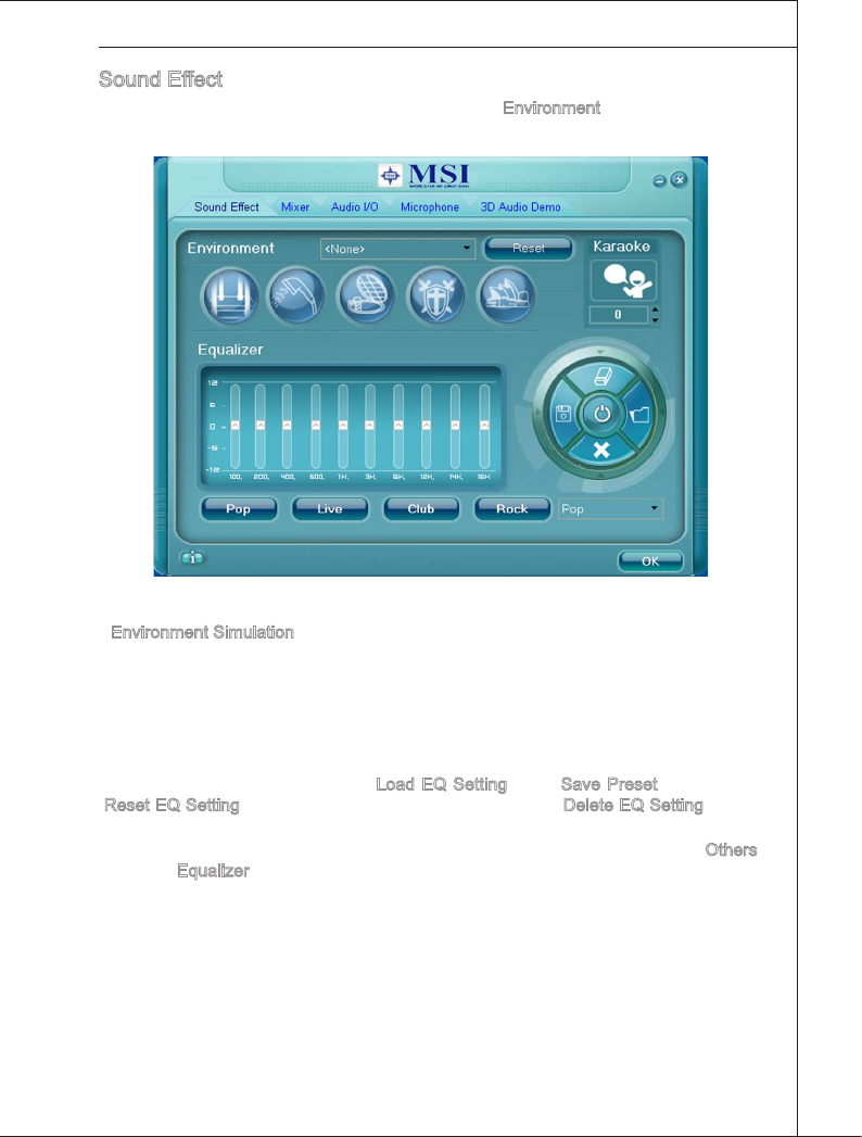
A-5
MS-7593
Sound Eect
Here you can select a sound eect you lke from the Envronment lst.
Envronment Smulaton
You wll be able to enjoy derent sound experence by pullng down the arrow, totally
23 knds of sound eect wll be shown for selecton. Realtek HD Audo Sound Manager
also provdes ve popular settngs “Stone Corrdor”, “Bathroom”, “Sewer ppe”, “Arena”
and “Audtorum” for quck enjoyment.
You may choose the provded sound eects, and the equalzer wll adjust automatcally.
If you lke, you may also load an equalzer settng or make an new equalzer settng to
save as an new one by usng the “Load EQ Settng” and “Save Preset” button, clck
“Reset EQ Settng” button to use the default value, or clck “Delete EQ Settng” button
to remove a preset EQ settng.
There are also other pre-set equalzer models for you to choose by clckng “Others”
under the Equalzer part.
■
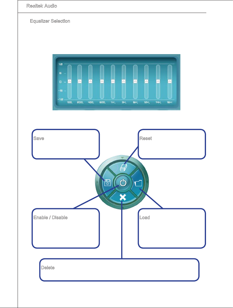
A-6
Realtek Audo
▍
Equalzer Selecton
Equalzer frees users from default settngs; users may create ther owned preferred
settngs by utlzng ths tool.
10 bands of equalzer, rangng from 100Hz to 16KHz.
■
Save
The settngs are saved perma-
nently for future use
Load
Whenever you would lke to
use preload settngs, smply
clck ths, the whole lst wll be
shown for your selecton.
Enable / Dsable
To dsable, you can temporar-
ly stop the sound eect wthout
losng the settngs
Reset
10 bands of equalzer would go
back to the default settng
Delete
To delete the pre-saved settngs whch are created from prevous steps.
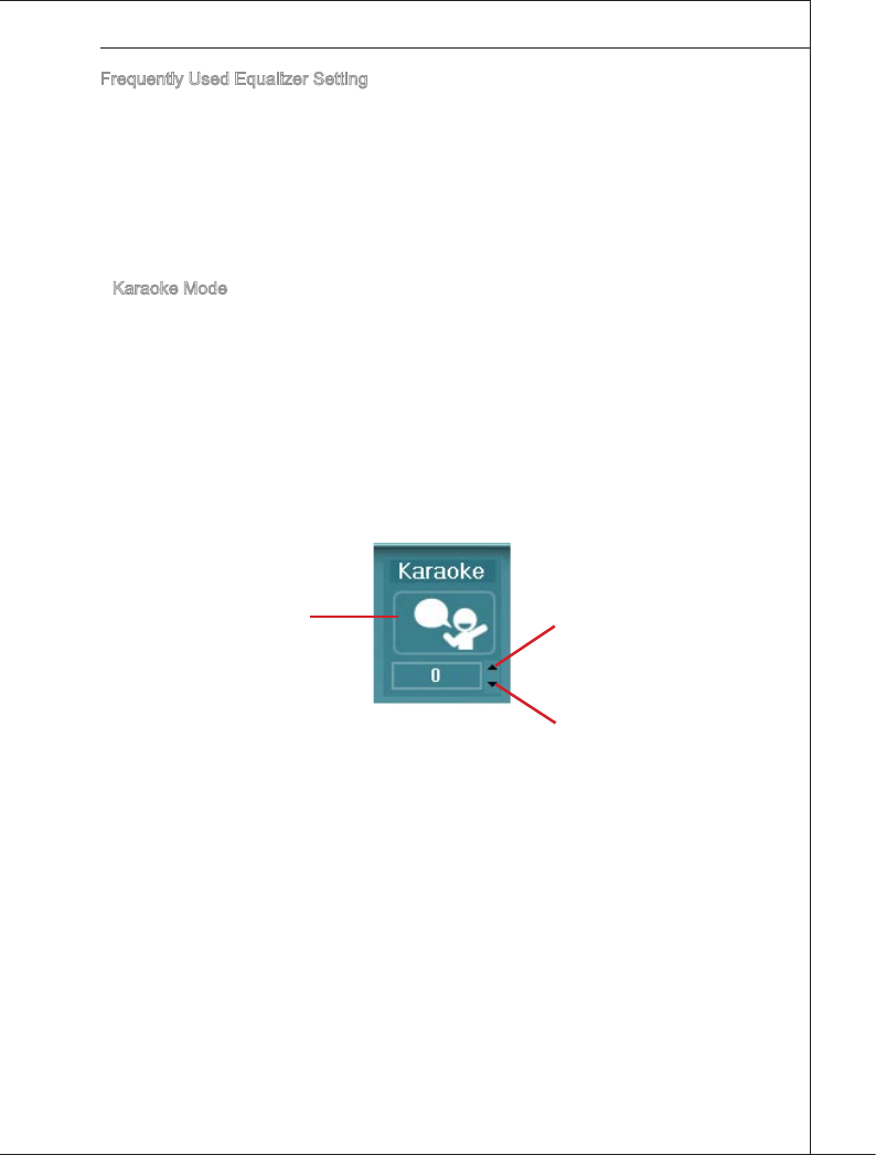
A-7
MS-7593
Frequently Used Equalzer Settng
Realtek recognzes the needs that you mght have. By leveragng our long experence at
audo eld, Realtek HD Audo Sound Manager provdes you certan optmzed equalzer
settngs that are frequently used for your quck enjoyment.
[How to Use It]
Other than the buttons “Pop”, “Lve”, “Club” & “Rock” shown on the page, to pull down
the arrow n “Others” you wll nd more optmzed settngs avalable to you.
Karaoke Mode
Karaoke mode brngs Karaoke fun back home. Smply usng the musc you usually play,
Karaoke mode can help you elmnate the vocal of the song or adjust the key to accom-
modate your range.
Vocal Cancellaton: Sngle clck on “Voce Cancellaton” the vocal of the song would
be elmnated, whle the background musc s stll n place, and you can be that
snger!
Key Adjustment: Usng “Up / Down Arrow” to nd a key whch better ts your vocal
range.
■
1.
2.
Rase the key
Lower the key
Remove the
human voce
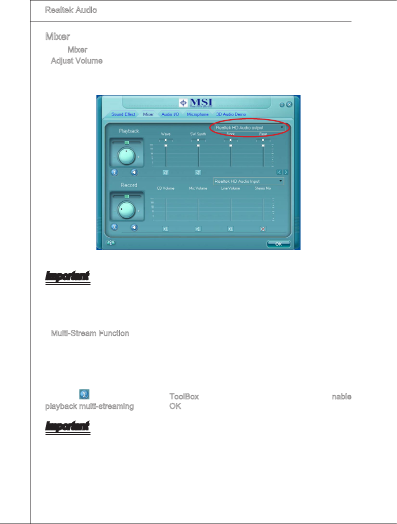
A-8
Realtek Audo
▍
Mxer
In the Mxer part, you may adjust the volumes of the rear and front panels ndvdually.
Adjust Volume
You can adjust the volume of the speakers that you pluged n front or rear panel by
select the Realtek HD Audo rear output or Realtek HD Audo front output tems.
Important
Before set up, please make sure the playback devces are well plugged n the jacks on
the rear or front panel. The Realtek HD Audo front output tem wll appear after you
plugng the speakers nto the jacks on the front panel.
Mult-Stream Functon
Realtek audo supports an outstandng feature called Mult-Stream, whch means you
may play derent audo sources smultaneously and let them output respectvely from
the ndcated real panel or front panel. Ths feature s very helpful when 2 people are
usng the same computer together for derent purposes.
Clck the button and the Mxer ToolBox menu wll appear. Then check the Enable
playback mult-streamng and clck OK to save the setup.
Important
You have to plug audo devce nto the jacks on the rear and front panel rst before en-
able the mult-stream functon.
■
■
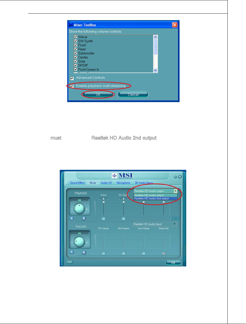
A-9
MS-7593
When you are playng the rst audo source (for example: use Wndows Meda Player
to play DVD/VCD), the output wll be played from the rear panel, whch s the default
settng.
Then you must to select the Realtek HD Audo 2nd output from the scroll lst rst, and
use a derent program to play the second audo source (for example: use Wnamp to
play MP3 les). You wll nd that the second audo source (MP3 musc) wll come out
from the Lne-Out audo jack of Front Panel.
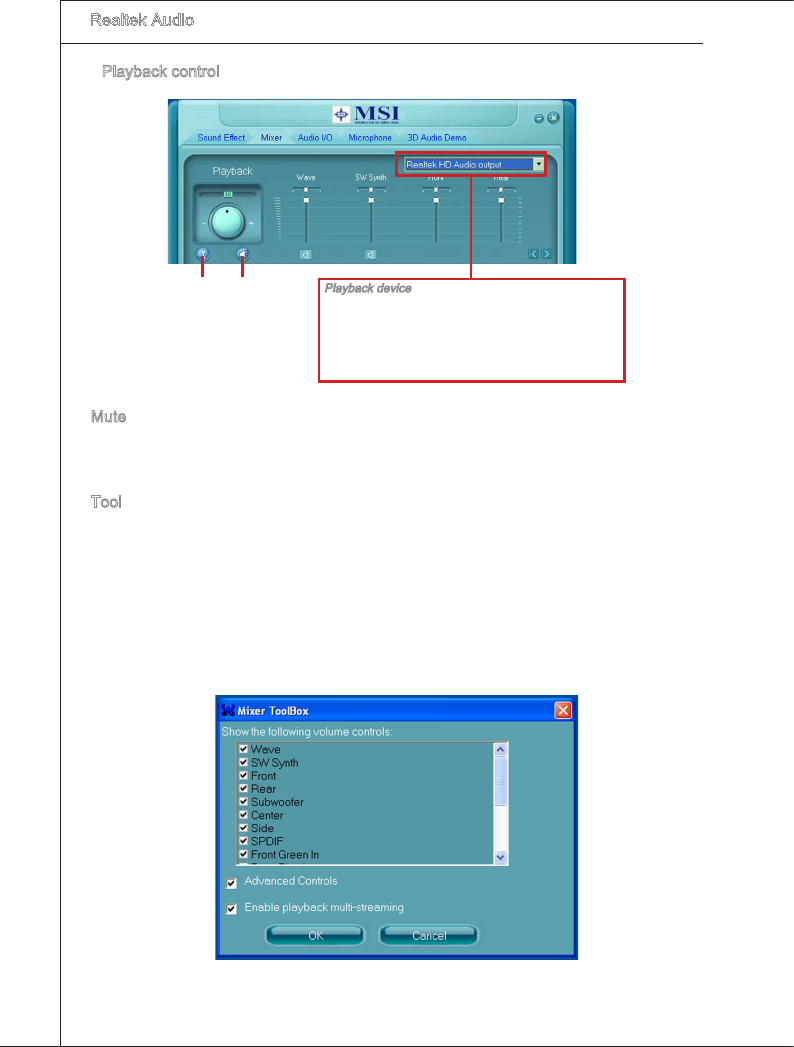
A-10
Realtek Audo
▍
Playback control
Playback devce
Ths functon s to let you freely decde whch ports
to output the sound. And ths s essental when mult-
streamng playback enabled.
- Realtek HD Audo Rear Output
- Realtek HD Audo Front Output
Tool Mute
Mute
You may choose to mute sngle or multple volume controls or to completely mute sound
output.
Tool
-
Show the followng volume controls
Ths s to let you freely decde whch volume control tems to be dsplayed.
- Advanced controls
-
Enable playback mult-streamng
Wth ths functon, you wll be able to have an audo chat wth your frends va headphone
(stream 1 from front panel) whle stll has musc (stream 2 from back panel) n play. At
any gven perod, you can have maxmum 2 streams operatng smultaneously.
■
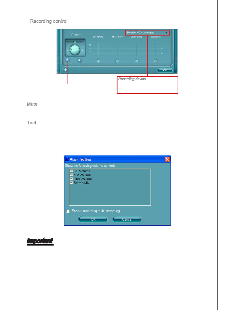
A-11
MS-7593
Recordng control
Recordng devce
-Back Lne n/ Mc, Front Ln n
-Realtek HD Audo Input
Tool Mute
Mute
You may choose to mute sngle or multple volume controls or to completely mute sound
nput.
Tool
- Show the followng volume controls
Ths s to let you freely decde whch volume control tems to be dsplayed.
- Enable recordng mult-streamng
Important
Realtek audo allows you to record the CD, Lne, Mc and Stereo Mx channels smul-
taneously, frees you from mxng eorts. At any gven perod, you may choose 1 of the
followng 4 channels to record.
■
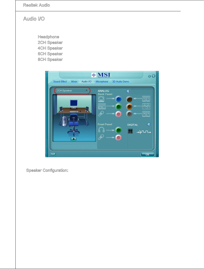
A-12
Realtek Audo
▍
Audo I/O
In ths tab, you can easly congure your mult-channel audo functon and speakers.
You can choose a desred mult-channel operaton here.
Headphone for the common headphone
2CH Speaker for Stereo-Speaker Output
4CH Speaker for 4-Speaker Output
6CH Speaker for 5.1-Speaker Output
8CH Speaker for 7.1-Speaker Output
Speaker Conguraton:
Plug the speakers n the correspondng jack.
Dalogue “connected devce” wll pop up for your selecton. Please select the devce
you have plugged n.
- If the devce s beng plugged nto the correct jack, you wll be able to nd the con
besde the jack changed to the one that s same as your devce.
- If not correct, Realtek HD Audo Manager wll gude you to plug the devce nto the
correct jack.
■
■
■
■
■
■
1.
2.
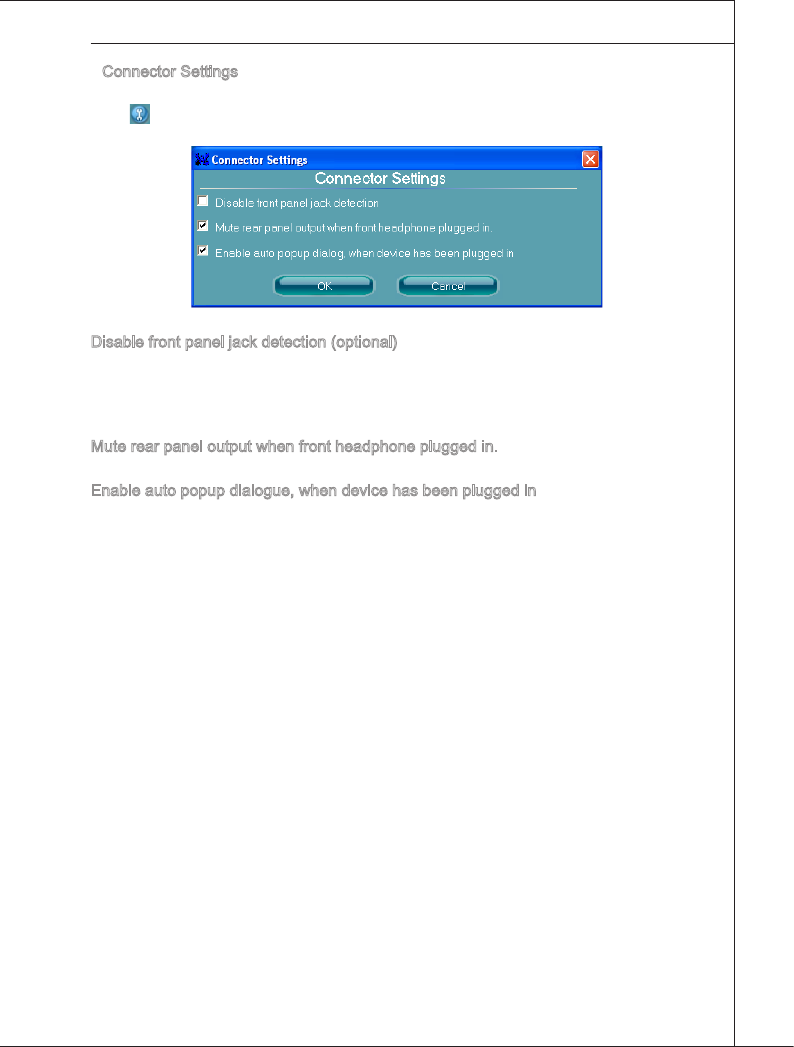
A-13
MS-7593
Connector Settngs
Clck to access connector settngs.
Dsable front panel jack detecton (optonal)
Jack detecton functon only works wth HD audo front panel. Please check f front jacks
on your system are so-called AC’97 jacks. If so, please check ths tem to dsable front
panel jack detecton.
Mute rear panel output when front headphone plugged n.
Enable auto popup dalogue, when devce has been plugged n
Once ths tem checked, the dalog “Connected devce” would automatcally pop up
when devce plugged n.
■
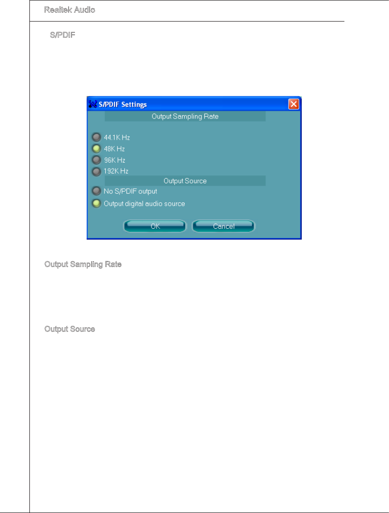
A-14
Realtek Audo
▍
S/PDIF
Short for Sony/Phlps Dgtal Interface, a standard audo le transfer format. S/PDIF al-
lows the transfer of dgtal audo sgnals from one devce to another wthout havng to be
converted rst to an analog format. Mantanng the vablty of a dgtal sgnal prevents
the qualty of the sgnal from degradng when t s converted to analog.
Output Samplng Rate
44.1KHz: Ths s recommend whle playng CD.
48KHz: Ths s recommended whle playng DVD or Dolby.
96KHz: Ths s recommended whle playng DVD-Audo.
192KHz: Ths s recommended whle playng Hgh qualty Audo.
Output Source
Output dgtal audo source: The dgtal audo format (such as .wav, .mp3,.md etc) wll
come out through S/PDIF-Out.
S/PDIF-n to S/PDIF -out pass though mode: The data from S/PDIF-In can be real-tme
played from S/PDIF-Out.
■
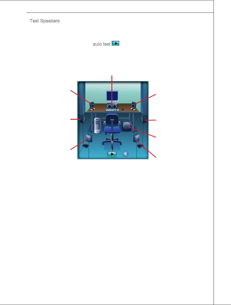
A-15
MS-7593
Test Speakers
You can select the speaker by clckng t to test ts functonalty. The one you select
wll lght up and make testng sound. If any speaker fals to make sound, then check
whether the cable s nserted rmly to the connector or replace the bad speakers wth
good ones. Or you may clck the auto test button to test the sounds of each speaker
automatcally.
Center
Front Rght
Sde Rght
Subwoofer
Rear Rght
Front Left
Sde Left
Rear Left
■
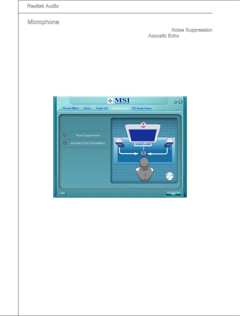
A-16
Realtek Audo
▍
Mcrophone
In ths tab you may set the functon of the mcrophone. Select the Nose Suppresson
to remove the possble nose durng recordng, or select Acoustc Echo Cancellaton to
cancel the acoustc echo durng recordng.
Acoustc Echo Cancellaton prevents playback sound from beng recorded by mcro-
phone together wth your sound. For example, you mght have chance to use VOIP
functon through Internet wth your frends. The voce of your frend wll come out from
speakers (playback). However, the voce of your frend mght also be recorded nto your
mcrophone then go back to your frend through Internet. In that case, your frend wll
hear hs/her own voce agan. Wth AEC (Acoustc Echo Cancellaton) enabled at your
sde, your frend can enjoy the benet wth less echo.
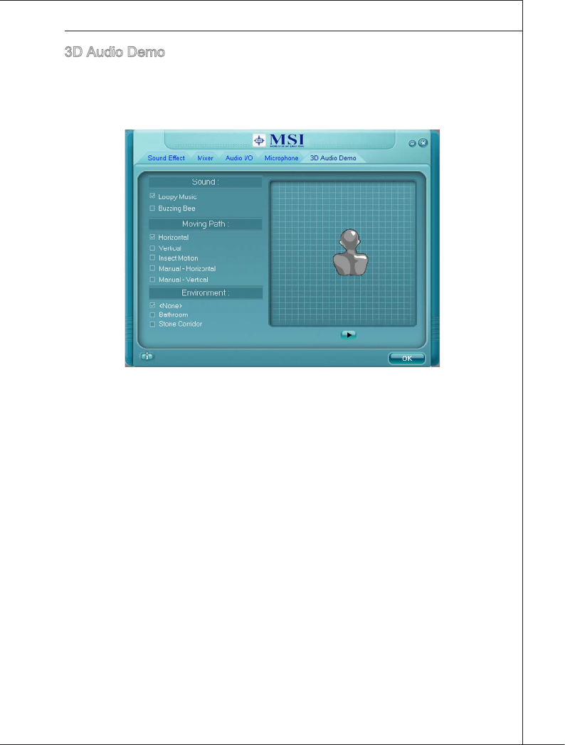
A-17
MS-7593
3D Audo Demo
In ths tab you may adjust your 3D postonal audo before playng 3D audo applcatons
lke gamng. You may also select derent envronment to choose the most sutable
envronment you lke.
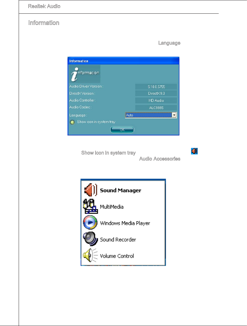
A-18
Realtek Audo
▍
Informaton
In ths tab t provdes some nformaton about ths HD Audo Conguraton utlty, nclud-
ng Audo Drver Verson, DrectX Verson, Audo Controller & Audo Codec. You may
also select the language of ths utlty by choosng from the Language lst.
Also there s a selecton Show con n system tray. Swtch t on and an con wll show
n the system tray. Rght-clck on the con and the Audo Accessores dalogue box wll
appear whch provdes several multmeda features for you to take advantage of.
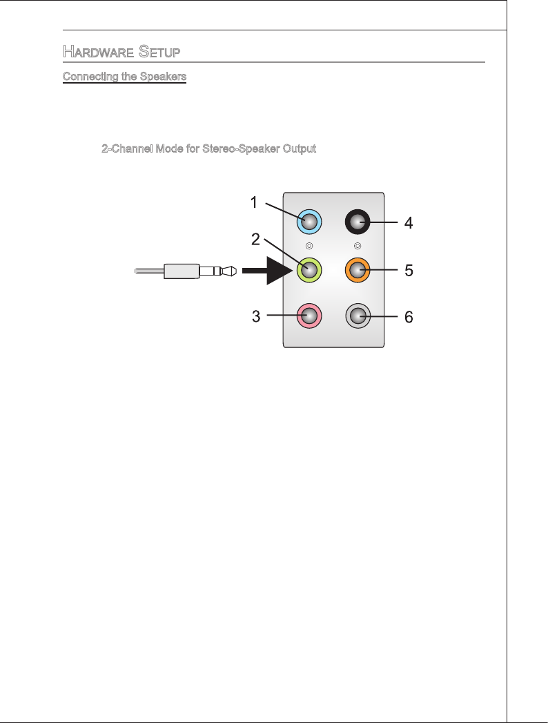
A-19
MS-7593
hardware Setup
Connectng the Speakers
When you have set the Mult-Channel Audo Functon mode properly n the software
utlty, connect your speakers to the correct phone jacks n accordance wth the settng
n software utlty.
2-Channel Mode for Stereo-Speaker Output
Lne In
Lne Out (Front channels)
MIC
No functon
No functon
No functon
■
1]
2]
3]
4]
5]
6]
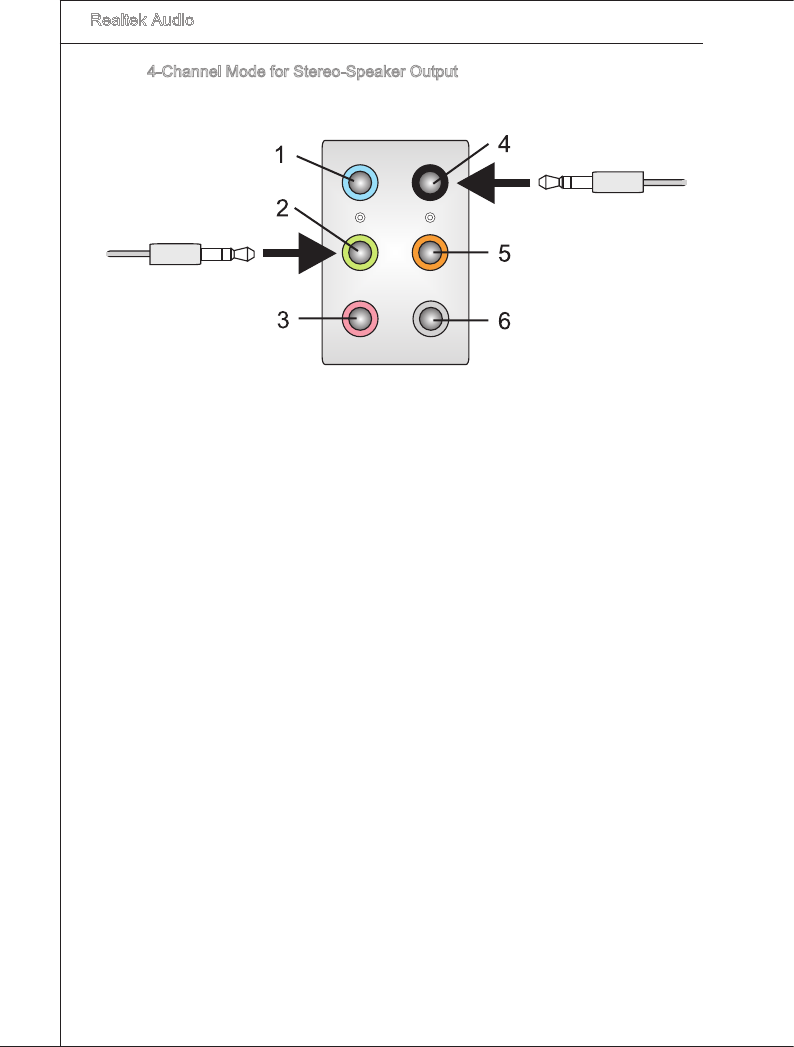
A-20
Realtek Audo
▍
4-Channel Mode for Stereo-Speaker Output
Lne In
Lne Out (Front channels)
MIC
Lne Out (Rear channels)
No functon
No functon
■
1]
2]
3]
4]
5]
6]
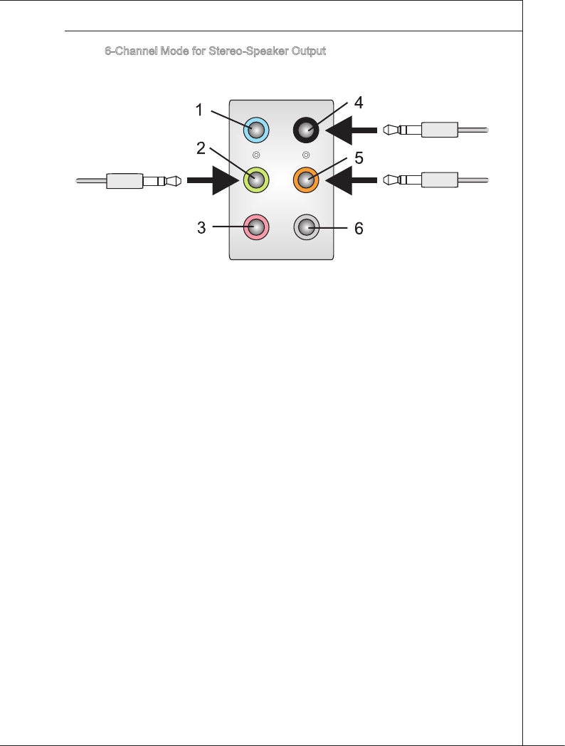
A-21
MS-7593
6-Channel Mode for Stereo-Speaker Output
Lne In
Lne Out (Front channels)
MIC
Lne Out (Rear channels)
Lne Out (Center and Subwoofer channel)
No functon
■
1]
2]
3]
4]
5]
6]
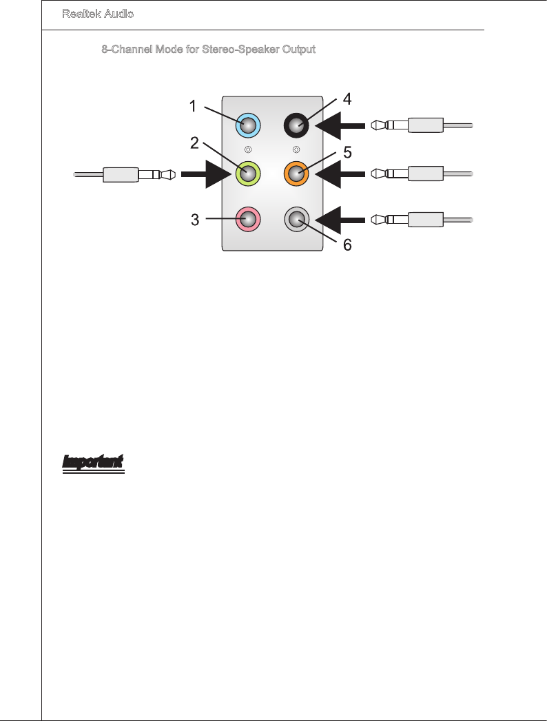
A-22
Realtek Audo
▍
8-Channel Mode for Stereo-Speaker Output
Lne In
Lne Out (Front channels)
MIC
Lne Out (Rear channels)
Lne Out (Center and Subwoofer channel)
Lne Out (Sde channels)
Important
To enable 7.1 channel audo-out functon on Wndows Vsta operatng system, you have
to nstall the Realtek Audo Drver. Or, the manboard wll support 5.1 channel audo-out
only.
■
1]
2]
3]
4]
5]
6]

B-1
Overclockng Center, the most useful and powerful utl-
ty that MSI has spent much research and eorts to de-
velop, helps users to montor or congure the hardware
status of MSI Manboard n wndows, such as CPU clock,
voltage, fan speed and temperature.
Before you nstall the Overclockng Center, please make
sure the system has meet the followng requrements:
256MB system memory.
CD-ROM drve for software nstallaton.
Operaton system: Wndows XP or up.
DotNet Frame Work 2.0
1.
2.
3.
4.
Appendx B
Overclockng Center
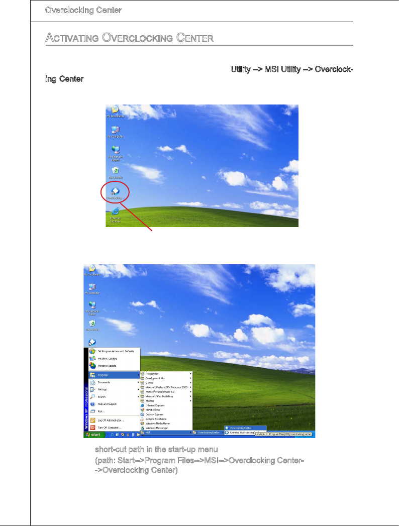
B-2
Overclockng Center
▍MS-7593
Overclockng Center
▍MS-7593
activating overcLocking center
Once you have your Overclockng Center nstalled (locate the setup source le n the
setup CD accompanyng wth your manboard, path: Utlty --> MSI Utlty --> Overclock-
ng Center), t wll have a short cut con on the desktop, and a short cut path n your
“Start-up” menu. You may double-clck on each con to actvate Overclockng Center.
short-cut con on the desktop
short-cut path n the start-up menu
(path: Start-->Program Fles-->MSI-->Overclockng Center-
->Overclockng Center)
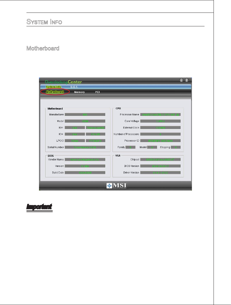
Overclockng Center
▍MS-7593
B-3
Overclockng Center
▍MS-7593
SySteM info
In the System Info screen, you can read the nformatons of manboard/ memory/ PCI.
Motherboard
Clck Motherboard to read the nformatons of manboard, manboard BIOS, nstalled
CPU and nstalled graphcs card.
Important
The pctures n ths appendx are for reference only and may vary from the product you
purchased. Please refer to the appearance of your system for detaled nformaton.
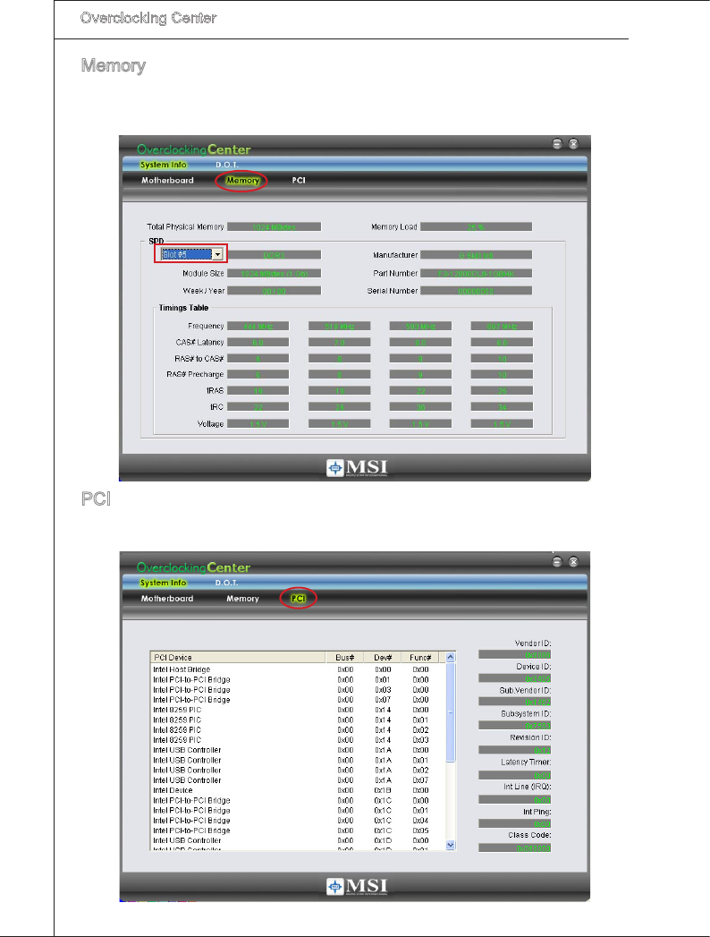
B-4
Overclockng Center
▍MS-7593
Overclockng Center
▍MS-7593
Memory
Clck Memory to read the nformaton of each memory DIMM slot. You can select a
DIMM slot you want to read from the SPD lst.
PCI
Clck PCI to read the nformaton of devces on the manboard.
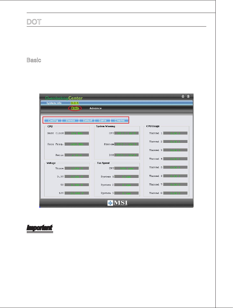
Overclockng Center
▍MS-7593
B-5
Overclockng Center
▍MS-7593
dot
Clck DOT to enter the DOT screen. In DOT, you can select the basc settng to reach
optmal performance n Basc menu or you can adjust advanced values for overclockng
n Advance menu.
Basc
In the Basc menu, t provdes one default settng and four common settngs for derent
envronments. You may choose one of the settngs that you need. The settngs n Basc
menu are not adjustable.
Important
You may change the values of each envronment settng/ default settng n Advance
menu. Please refer the followng secton for more detals.
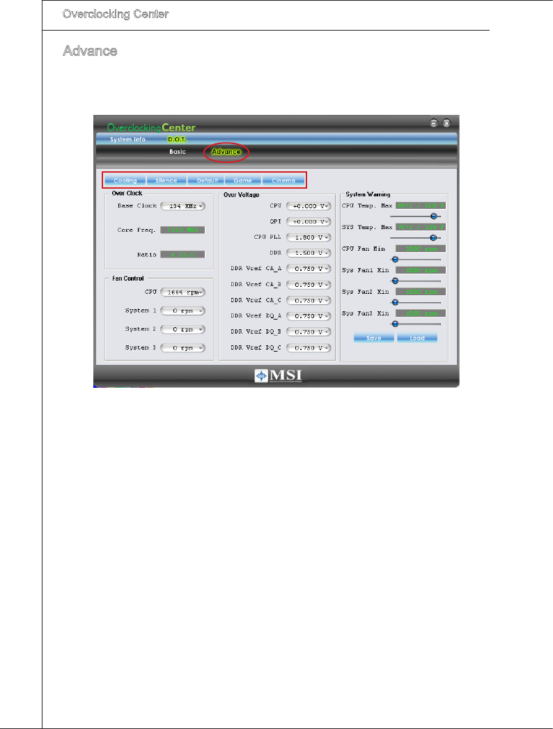
B-6
Overclockng Center
▍MS-7593
Overclockng Center
▍MS-7593
Advance
In the Advance menu, you can adjust the values for each envronment settng/ default
settng. Clck the Coolng/ Slence/ Default/ Game/ Cnema button to enter t’s settng
menu. Please refer to the followng descrptons to adjust the values and save them.
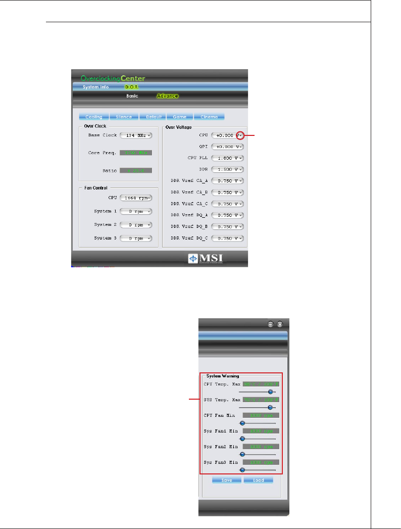
Overclockng Center
▍MS-7593
B-7
Overclockng Center
▍MS-7593
In each settng menu, you can select desred values for manual overclockng. Smply
clck the rght sde of the button whch arranges an arrow sgn, and a drop-down menu
wll appear below the button, then select a value.
Clck the arrow sgn
and the drop-down
menu wll appear.
In the “System Warnng” block, you can set the maxmum CPU/ system temperature
and the mnmum CPU/ system fan speed by usng the scroll bar. The system wll pop-
up a warnng message to warnng you when the temperature/ fan speed s over/ lower
the values you set.
Set the thresholds of
CPU temperture &
CPU FAN speed.
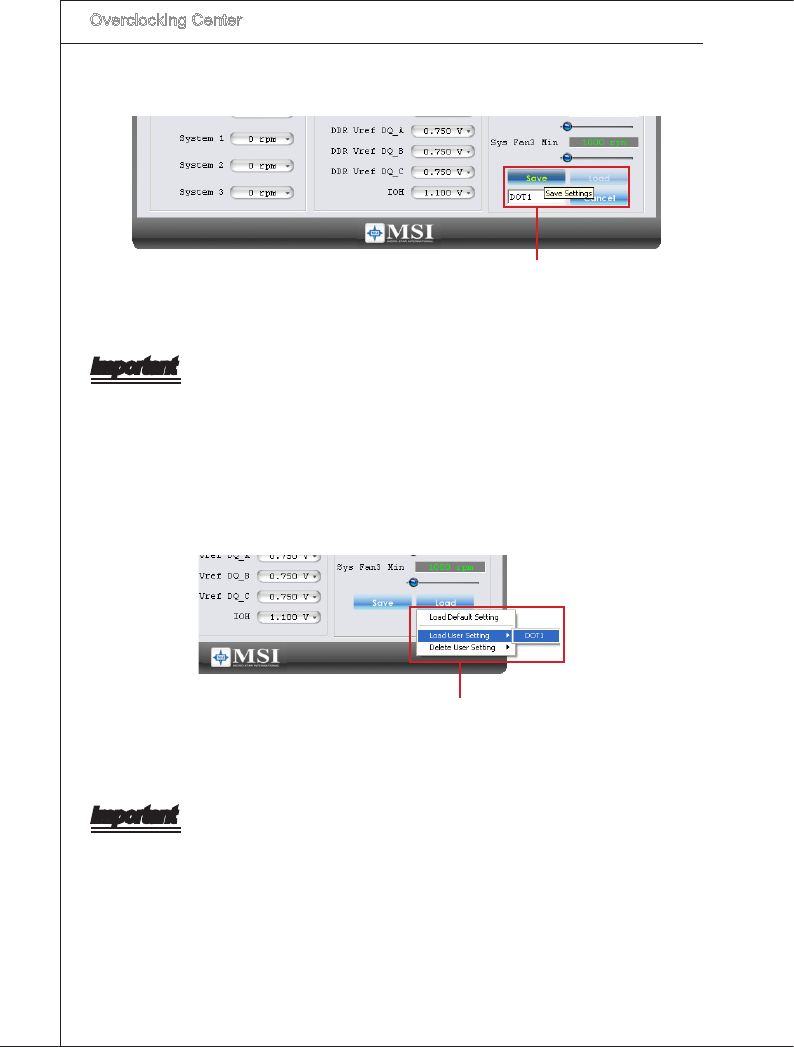
B-8
Overclockng Center
▍MS-7593
After you adjust the values n settng menu, you can save t for future use.
Clck the Save button, and enter a name n
the empty box. Then, clck Save button agan
to save the settngs.
Important
It provdes you to save up to 20 user settngs.
Clck the Load button and choose a saved user settng to load the settngs for the sys-
tem.
Clck the Load button, and
choose a saved user settng.
Important
Every tme you turn-o the system, the settngs wll be restored to the factory default.
If you want to use the saved settngs, you have to load t after enterng the operatng
system every tme.
