Msi Z77A G43 Gaming Owner S Manual
2014-07-06
: Msi Msi-Z77A-G43-Gaming-Owner-S-Manual msi-z77a-g43-gaming-owner-s-manual msi pdf
Open the PDF directly: View PDF ![]() .
.
Page Count: 98
- Copyright Notice
- Trademarks
- Revision History
- Technical Support
- Safety Instructions
- FCC-B Radio Frequency Interference Statement
- CE Conformity
- Radiation Exposure Statement
- European Community Compliance Statement
- Taiwan Wireless Statements
- Japan VCCI Class B Statement
- Korea Warning Statements
- Battery Information
- Chemical Substances Information
- WEEE (Waste Electrical and Electronic Equipment) Statement
- Chapter 1
- Getting Started
- Chapter 2
- BIOS Setup
- Appendix A
- Realtek Audio
- Appendix B
- Intel RAID
- Appendix C
- Install Windows XP Notes
- Appendix D
- Intel SBA
- CPU & Cooler Installation
- CPUFAN,SYSFAN1~4: Fan Power Connectors
- Dual-Channel mode Population Rule
- JAUD1: Front Panel Audio Connector
- JBAT1: Clear CMOS Jumper
- JCI1: Chassis Intrusion Connector
- JCOM1: Serial Port Connector
- JDLED3: Voice Genie Connector (optional)
- JFP1, JFP2: Front Panel Connectors
- JLPT1: Parallel Port Connector
- JPWR1: ATX 24-pin Power Connector
- JPWR2: ATX 8-pin Power Connector
- JTPM1: TPM Module Connector
- JTURBO1: MultiConnect Panel Connector (optional)
- JUSB1~2: USB 2.0 Expansion Connector
- JUSB3: USB 3.0 Expansion Connector
- PCIe Expansion Slot
- PCI Expansion Slot
- SATA1~6: SATA Connectors
Z77A-G43 GAMING
B75A-G43 GAMING
MS-7758 (v5.x) Manboard
G52-77581XT
Preface
MS-7758
Preface
Preface
MS-7758
Preface
Copyrght Notce
The materal n ths document s the ntellectual property of MICRO-STAR INTERNA-
TIONAL. We take every care n the preparaton of ths document, but no guarantee s
gven as to the correctness of ts contents. Our products are under contnual mprove-
ment and we reserve the rght to make changes wthout notce.
Trademarks
All trademarks n ths manual are propertes of ther respectve owners.
MSI® s regstered trademark of Mcro-Star Int’l Co.,Ltd.
NVIDIA® s regstered trademark of NVIDIA Corporaton.
ATI® s regstered trademark of AMD Corporaton.
AMD® s regstered trademarks of AMD Corporaton.
Intel® s regstered trademarks of Intel Corporaton.
Wndows® s regstered trademarks of Mcrosoft Corporaton.
AMI® s regstered trademark of Amercan Megatrends Inc.
Award® s a regstered trademark of Phoenx Technologes Ltd.
Sound Blaster® s regstered trademark of Creatve Technology Ltd.
Realtek® s regstered trademark of Realtek Semconductor Corporaton.
JMcron® s regstered trademark of JMcron Technology Corporaton.
Netware® s a regstered trademark of Novell, Inc.
Lucd® s trademarks of LucdLogx Technologes, Ltd.
VIA® s regstered trademark of VIA Technologes, Inc.
ASMeda® s regstered trademark of ASMeda Technology Inc.
Pad, Phone, and Pod are trademarks of Apple Inc.
Revson Hstory
Revson Revson Hstory Date
V5.0 Frst release for PCB 5.X 2013/ 03
■
■
■
■
■
■
■
■
■
■
■
■
■
■
■
■
Preface
MS-7758
Preface
Preface
MS-7758
Preface
Techncal Support
If a problem arses wth your system and no soluton can be obtaned from the user’s
manual, please contact your place of purchase or local dstrbutor. Alternatvely, please
try the followng help resources for further gudance.
Vst the MSI webste for techncal gude, BIOS
updates, drver updates, and other nformaton:
http://www.ms.com/servce/download/
Contact our techncal sta at:
http://support.ms.com
Safety Instructons
Always read the safety nstructons carefully.
Keep ths User’s Manual for future reference.
Keep ths equpment away from humdty.
Lay ths equpment on a relable at surface before settng t up.
The openngs on the enclosure are for ar convecton hence protects the equpment
from overheatng. DO NOT COVER THE OPENINGS.
Make sure the voltage of the power source s at 110/220V before connectng the
equpment to the power nlet.
Place the power cord such a way that people can not step on t. Do not place
anythng over the power cord.
Always Unplug the Power Cord before nsertng any add-on card or module.
All cautons and warnngs on the equpment should be noted.
Never pour any lqud nto the openng that can cause damage or cause electrcal
shock.
If any of the followng stuatons arses, get the equpment checked by servce
personnel:
The power cord or plug s damaged.
Lqud has penetrated nto the equpment.
The equpment has been exposed to mosture.
The equpment does not work well or you can not get t work accordng to User’s
Manual.
The equpment has been dropped and damaged.
The equpment has obvous sgn of breakage.
DO NOT LEAVE THIS EQUIPMENT IN AN ENVIRONMENT ABOVE 60oC (140oF),
IT MAY DAMAGE THE EQUIPMENT.
■
■
■
■
■
■
■
■
■
■
■
◯
◯
◯
◯
◯
◯
■
v
Preface
MS-7758
Preface
Preface
MS-7758
Preface
CE Conformty
Hereby, Mcro-Star Internatonal CO., LTD declares that ths devce s
n complance wth the essental safety requrements and other relevant
provsons set out n the European Drectve.
FCC-B Rado Frequency Interference Statement
Ths equpment has been tested and found to comply wth the lmts for a Class B dgtal
devce, pursuant to Part 15 of the FCC Rules. These lmts are desgned to provde
reasonable protecton aganst harmful nterference n a resdental nstallaton. Ths
equpment generates, uses and can radate rado frequency energy and, f not nstalled
and used n accordance wth the nstructons, may cause harmful nterference to rado
communcatons. However, there s no guarantee that nterference wll not occur n a
partcular nstallaton. If ths equpment does cause harmful nterference to rado or
televson recepton, whch can be determned by turnng the equpment o and on, the
user s encouraged to try to correct the nterference by one or more of the measures
lsted below.
Reorent or relocate the recevng antenna.
Increase the separaton between the equpment and recever.
Connect the equpment nto an outlet on a crcut derent from that to whch the
recever s connected.
Consult the dealer or an experenced rado/televson techncan for help.
Notce 1
The changes or modcatons not expressly approved by the party responsble for
complance could vod the user’s authorty to operate the equpment.
Notce 2
Shelded nterface cables and A.C. power cord, f any, must be used n order to comply
wth the emsson lmts.
VOIR LA NOTICE D’INSTALLATION AVANT DE RACCORDER AU RESEAU.
◯
◯
◯
◯
Ths devce comples wth Part 15 of the FCC Rules. Operaton s subject to the followng
two condtons:
ths devce may not cause harmful nterference, and
ths devce must accept any nterference receved, ncludng nterference that may
cause undesred operaton.
1)
2)
Mcro-Star Internatonal
MS-7758

Preface
MS-7758
Preface
v
Preface
MS-7758
Preface
Radaton Exposure Statement
Ths equpment comples wth FCC radaton exposure lmts set forth for an uncon-
trolled envronment. Ths equpment and ts antenna should be nstalled and operated
wth mnmum dstance 20 cm between the radator and your body. Ths equpment and
ts antenna must not be co-located or operatng n conjuncton wth any other antenna
or transmtter.
European Communty Complance Statement
The equpment comples wth the RF Exposure Requrement 1999/519/EC, Councl
Recommendaton of 12 July 1999 on the lmtaton of exposure of the general publc
to electromagnetc elds (0–300GHz). Ths wreless devce comples wth the R&TTE
Drectve.
Tawan Wreless Statements
無線設備警告聲明
經型式認證合格之低功率射頻電機,非經許可,公司、商號或使用者均不得擅自變更頻
率、加大功率或變更原設計之特性及功能。
低功率射頻電機之使用不得影響飛航安全及干擾合法通信;經發現有干擾現象時,應立
即停用,並改善至無干擾時方得繼續使用。前項合法通信,指依電信法規定作業之無線
電通信。低功率射頻電機須忍受合法通信或工業、科學及醫療用電波輻射性電機設備之
干擾。
警告使用者:這是甲類資訊產品,在居住的環境中使用時,可能會造成無線電干擾,在
這種情況下,使用者會被要求採取某些適當的對策。
Japan VCCI Class B Statement
クラス B 情報技術装置
この装置は、情報技術装置等電波障害自主規制協議会(VCCI)の基準に基づくクラ
スB情報技術装置です。この装置が家庭内でラジオやテレビジョン受信機に近接して
使われると、受信障害を引き起こすことがあります。取扱説明書にしたがって正しい
取り扱いをしてください。
Korea Warnng Statements
당해 무선설비는 운용중 전파혼신 가능성이 있음
v
Preface
MS-7758
Preface
Preface
MS-7758
Preface
Calforna, USA:
The button cell battery may contan perchlorate materal and requres
specal handlng when recycled or dsposed of n Calforna.
For further nformaton please vst:
http://www.dtsc.ca.gov/hazardouswaste/perchlorate/
Tawan:
For better envronmental protecton, waste batteres should be collected
separately for recyclng or specal dsposal.
廢電池請回收
European Unon:
Batteres, battery packs, and accumulators should not be dsposed of as
unsorted household waste. Please use the publc collecton system to
return, recycle, or treat them n complance wth the local regulatons.
Battery Informaton
Chemcal Substances Informaton
In complance wth chemcal substances regulatons, such as the EU REACH Regulaton
(Regulaton EC No. 1907/2006 of the European Parlament and the Councl), MSI
provdes the nformaton of chemcal substances n products at:
http://www.ms.com/html/popup/csr/evmtprtt_pcm.html
CAUTION: There s a rsk of exploson, f battery s ncorrectly replaced.
Replace only wth the same or equvalent type recommended by the manufacturer.
Preface
MS-7758
Preface
v
Preface
MS-7758
Preface
WEEE (Waste Electrcal and Electronc Equpment) Statement
ENGLISH
To protect the global envronment and as an envronmentalst, MSI must re-
mnd you that...
Under the European Unon (“EU”) Drectve on Waste Electrcal and Elec-
tronc Equpment, Drectve 2002/96/EC, whch takes eect on August 13,
2005, products of “electrcal and electronc equpment” cannot be dscarded
as muncpal wastes anymore, and manufacturers of covered electronc equpment wll
be oblgated to take back such products at the end of ther useful lfe. MSI wll comply
wth the product take back requrements at the end of lfe of MSI-branded products that
are sold nto the EU. You can return these products to local collecton ponts.
DEUTSCH
Hnwes von MSI zur Erhaltung und Schutz unserer Umwelt
Gemäß der Rchtlne 2002/96/EG über Elektro- und Elektronk-Altgeräte dürfen Elek-
tro- und Elektronk-Altgeräte ncht mehr als kommunale Abfälle entsorgt werden. MSI
hat europawet verschedene Sammel- und Recyclngunternehmen beauftragt, de n
de Europäsche Unon n Verkehr gebrachten Produkte, am Ende senes Lebenszyklus
zurückzunehmen. Btte entsorgen Se deses Produkt zum gegebenen Zetpunkt aus-
schlesslch an ener lokalen Altgerätesammelstelle n Ihrer Nähe.
FRANÇAIS
En tant qu’écologste et an de protéger l’envronnement, MSI tent à rappeler cec...
Au sujet de la drectve européenne (EU) relatve aux déchets des équpement élec-
trques et électronques, drectve 2002/96/EC, prenant eet le 13 août 2005, que les
produts électrques et électronques ne peuvent être déposés dans les décharges ou
tout smplement ms à la poubelle. Les fabrcants de ces équpements seront oblgés de
récupérer certans produts en n de ve. MSI prendra en compte cette exgence relatve
au retour des produts en n de ve au sen de la communauté européenne. Par con-
séquent vous pouvez retourner localement ces matérels dans les ponts de collecte.
РУССКИЙ
Компания MSI предпринимает активные действия по защите окружающей среды,
поэтому напоминаем вам, что....
В соответствии с директивой Европейского Союза (ЕС) по предотвращению
загрязнения окружающей среды использованным электрическим и электронным
оборудованием (директива WEEE 2002/96/EC), вступающей в силу 13
августа 2005 года, изделия, относящиеся к электрическому и электронному
оборудованию, не могут рассматриваться как бытовой мусор, поэтому
производители вышеперечисленного электронного оборудования обязаны
принимать его для переработки по окончании срока службы. MSI обязуется
соблюдать требования по приему продукции, проданной под маркой MSI на
территории EC, в переработку по окончании срока службы. Вы можете вернуть
эти изделия в специализированные пункты приема.

v
Preface
MS-7758
Preface
Preface
MS-7758
Preface
ESPAÑOL
MSI como empresa comprometda con la proteccón del medo ambente, recomenda:
Bajo la drectva 2002/96/EC de la Unón Europea en matera de desechos y/o equ-
pos electróncos, con fecha de rgor desde el 13 de agosto de 2005, los productos
clascados como “eléctrcos y equpos electróncos” no pueden ser depostados en
los contenedores habtuales de su muncpo, los fabrcantes de equpos electróncos,
están oblgados a hacerse cargo de dchos productos al termno de su período de vda.
MSI estará comprometdo con los térmnos de recogda de sus productos venddos en
la Unón Europea al nal de su perodo de vda. Usted debe depostar estos productos
en el punto lmpo establecdo por el ayuntamento de su localdad o entregar a una
empresa autorzada para la recogda de estos resduos.
NEDERLANDS
Om het mleu te beschermen, wl MSI u eraan hernneren dat….
De rchtljn van de Europese Une (EU) met betrekkng tot Vervulng van Electrsche
en Electronsche producten (2002/96/EC), de op 13 Augustus 2005 n zal gaan kun-
nen net meer beschouwd worden als vervulng. Fabrkanten van dt soort producten
worden verplcht om producten retour te nemen aan het end van hun levenscyclus.
MSI zal overeenkomstg de rchtljn handelen voor de producten de de merknaam MSI
dragen en verkocht zjn n de EU. Deze goederen kunnen geretourneerd worden op
lokale nzamelngspunten.
SRPSKI
Da b zašttl prrodnu srednu, kao preduzeće koje vod računa o okoln prrodnoj
sredn, MSI mora da vas podest da…
Po Drektv Evropske unje (“EU”) o odbačenoj ekektronskoj elektrčnoj oprem, D-
rektva 2002/96/EC, koja stupa na snagu od 13. Avgusta 2005, prozvod koj spadaju
pod “elektronsku elektrčnu opremu” ne mogu vše bt odbačen kao občan otpad
prozvođač ove opreme bće prnuđen da uzmu natrag ove prozvode na kraju njhovog
uobčajenog veka trajanja. MSI će poštovat zahtev o preuzmanju ovakvh prozvoda
kojma je stekao vek trajanja, koj maju MSI oznaku koj su prodat u EU. Ove proz-
vode možete vratt na lokalnm mestma za prkupljanje.
POLSKI
Aby chronć nasze środowsko naturalne oraz jako rma dbająca o ekologę, MSI przy-
pomna, że...
Zgodne z Dyrektywą Un Europejskej (“UE”) dotyczącą odpadów produktów elektry-
cznych elektroncznych (Dyrektywa 2002/96/EC), która wchodz w życe 13 serpna
2005, tzw. “produkty oraz wyposażene elektryczne elektronczne “ ne mogą być trak-
towane jako śmec komunalne, tak węc producenc tych produktów będą zobowązan
do odberana ch w momence gdy produkt jest wycofywany z użyca. MSI wypełn
wymagana UE, przyjmując produkty (sprzedawane na terene Un Europejskej) wy-
cofywane z użyca. Produkty MSI będze można zwracać w wyznaczonych punktach
zborczych.

Preface
MS-7758
Preface
x
Preface
MS-7758
Preface
TÜRKÇE
Çevrec özellğyle blnen MSI dünyada çevrey korumak çn hatırlatır:
Avrupa Brlğ (AB) Kararnames Elektrk ve Elektronk Malzeme Atığı, 2002/96/EC
Kararnames altında 13 Ağustos 2005 tarhnden tbaren geçerl olmak üzere, elektrkl
ve elektronk malzemeler dğer atıklar gb çöpe atılamayacak ve bu elektonk chazların
üretcler, chazların kullanım süreler bttkten sonra ürünler ger toplamakla yükümlü
olacaktır. Avrupa Brlğ’ne satılan MSI markalı ürünlern kullanım süreler bttğnde MSI
ürünlern ger alınması steğ le şbrlğ çersnde olacaktır. Ürünlernz yerel toplama
noktalarına bırakablrsnz.
ČESKY
Záleží nám na ochraně žvotního prostředí - společnost MSI upozorňuje...
Podle směrnce Evropské une (“EU”) o lkvdac elektrckých a elektronckých výrobků
2002/96/EC platné od 13. srpna 2005 je zakázáno lkvdovat “elektrcké a elektroncké
výrobky” v běžném komunálním odpadu a výrobc elektronckých výrobků, na které se
tato směrnce vztahuje, budou povnn odebírat takové výrobky zpět po skončení je-
jch žvotnost. Společnost MSI splní požadavky na odebírání výrobků značky MSI,
prodávaných v zemích EU, po skončení jejch žvotnost. Tyto výrobky můžete odevzdat
v místních sběrnách.
MAGYAR
Annak érdekében, hogy környezetünket megvédjük, lletve környezetvédőként fellépve
az MSI emlékeztet Önt, hogy ...
Az Európa Unó („EU”) 2005. augusztus 13-án hatályba lépő, az elektromos és elek-
tronkus berendezések hulladékaról szóló 2002/96/EK rányelve szernt az elektromos
és elektronkus berendezések többé nem kezelhetőek lakosság hulladékként, és az
lyen elektronkus berendezések gyártó kötelessé válnak az lyen termékek vsszavé-
telére azok hasznos élettartama végén. Az MSI betartja a termékvsszavétellel kapc-
solatos követelményeket az MSI márkanév alatt az EU-n belül értékesített termékek
esetében, azok élettartamának végén. Az lyen termékeket a legközelebb gyűjtőhelyre
vhet.
ITALIANO
Per proteggere l’ambente, MSI, da sempre amca della natura, t rcorda che….
In base alla Drettva dell’Unone Europea (EU) sullo Smaltmento de Materal Elettrc
ed Elettronc, Drettva 2002/96/EC n vgore dal 13 Agosto 2005, prodott appartenent
alla categora de Materal Elettrc ed Elettronc non possono pù essere elmnat come
rut muncpal: produttor d dett materal saranno obblgat a rtrare ogn prodotto
alla ne del suo cclo d vta. MSI s adeguerà a tale Drettva rtrando tutt prodott
marchat MSI che sono stat vendut all’nterno dell’Unone Europea alla ne del loro
cclo d vta. È possble portare prodott nel pù vcno punto d raccolta
x
Preface
MS-7758
Preface
Preface
MS-7758
Preface
CONTENTS
▍
Copyrght Notce ............................................................................................
Trademarks ....................................................................................................
Revson Hstory.............................................................................................
Techncal Support..........................................................................................
Safety Instructons .........................................................................................
FCC-B Rado Frequency Interference Statement.......................................... v
CE Conformty ............................................................................................... v
Radaton Exposure Statement ....................................................................... v
European Communty Complance Statement ............................................... v
Tawan Wreless Statements .......................................................................... v
Japan VCCI Class B Statement ..................................................................... v
Korea Warnng Statements ............................................................................ v
Battery Informaton ........................................................................................ v
Chemcal Substances Informaton ................................................................. v
WEEE (Waste Electrcal and Electronc Equpment) Statement ...................v
Chapter 1 Gettng Started............................................................................1-1
Packng Contents ................................................................................................. 1-2
Optonal Accessores ........................................................................................... 1-2
Assembly Precautons ..........................................................................................1-3
Manboard Speccatons ..................................................................................... 1-4
Connectors Quck Gude ...................................................................................... 1-6
Back Panel Quck Gude ......................................................................................1-8
CPU (Central Processng Unt) .......................................................................... 1-10
Mountng Screw Holes .......................................................................................1-14
Power Supply ..................................................................................................... 1-15
Memory ..............................................................................................................1-16
Expanson Slots ................................................................................................. 1-18
Vdeo/ Graphcs Cards ...................................................................................... 1-19
Internal Connectors ............................................................................................1-22
Jumper ...............................................................................................................1-30
Drvers and Utltes ............................................................................................1-31
Preface
MS-7758
Preface
x
Preface
MS-7758
Preface
Chapter 2 BIOS Setup .................................................................................2-1
Enterng ................................................................................................................2-2
Overvew ..............................................................................................................2-2
Boot devce prorty bar ........................................................................................ 2-3
Operaton ............................................................................................................. 2-4
SETTINGS ...........................................................................................................2-5
OC ...................................................................................................................... 2-13
ECO ................................................................................................................... 2-18
BROWSER .........................................................................................................2-19
Installng Wnk ...................................................................................................2-19
UTILITIES .......................................................................................................... 2-20
Updatng the BIOS wth Lve Update ..................................................................2-22
SECURITY ......................................................................................................... 2-23
Appendx A Realtek Audo .......................................................................... A-1
Software Conguraton .........................................................................................A-2
Hardware Default Settng .....................................................................................A-4
Appendx B Intel RAID ................................................................................ B-1
Introducton ..........................................................................................................B-2
Usng Intel Rapd Storage Technology Opton ROM............................................B-3
Installng Drver ..................................................................................................B-10
Degraded RAID Array ........................................................................................B-12
System Acceleraton (optonal) ..........................................................................B-14
RST Synchronzaton (optonal) .........................................................................B-16
Appendx C Install Wndows XP Notes ....................................................... C-1
Installng Wndows XP wth IDE Mode ................................................................ C-2
Installng Wndows XP wth AHCI Mode .............................................................. C-3
Appendx D Intel SBA ................................................................................. D-1
Prerequstes ....................................................................................................... D-2
Installng Intel SBA .............................................................................................. D-3
Software Conguraton ........................................................................................ D-3
Help Button ......................................................................................................... D-4

Thank you for choosng the Z77A-G43 GAMING/
B75A-G43 GAMING Seres (MS-7758 v5.X) ATX
motherboard. The Seres manboards are based on
Intel® Z77/ B75 chpset for optmal system ecency.
Desgned to t the advanced Intel® LGA1155
processor, these Seres manboards delver a hgh
performance and professonal desktop platform
soluton.
Chapter 1
Gettng Started
1-2
Gettng Started
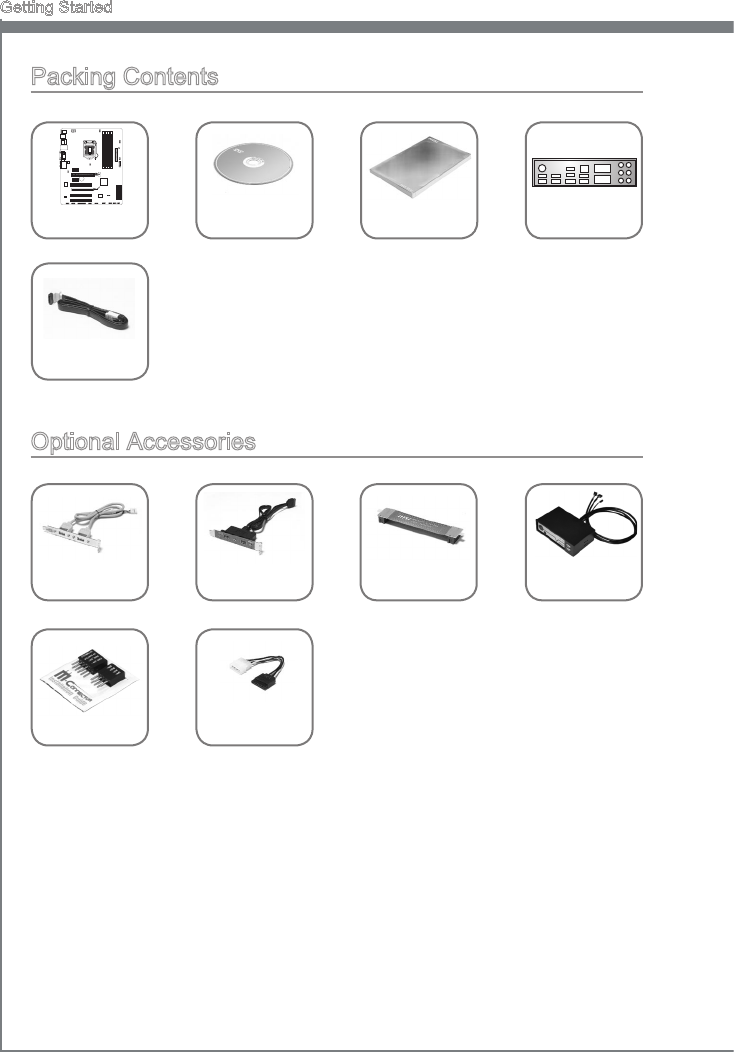
Packng Contents
Manboard Drver / Utlty
DVD User Gude Back IO Sheld
SATA Cable
* These pctures are for reference only and may vary wthout notce.
* The packng contents may vary accordng to the model you purchased.
* If you need to purchase the optonal accessores or request part numbers, please
vst the MSI webste at http://www.ms.com/ndex.php or consult the dealer.
Optonal Accessores
M-Connector SATA Power
Cable
USB 2.0
Bracket USB 3.0
Bracket
CrossFre
Cable
MSI
MultConnect
Panel
BATT
+
1-3
MS-7758
Chapter 1
Assembly Precautons
The components ncluded n ths package are prone to damage from electrostatc
dscharge (ESD). Please adhere to the followng nstructons to ensure successful
computer assembly.
Always turn o the power supply and unplug the power cord from the power outlet
before nstallng or removng any computer component.
Ensure that all components are securely connected. Loose connectons may cause
the computer to not recognze a component or fal to start.
Hold the manboard by the edges to avod touchng senstve components.
It s recommended to wear an electrostatc dscharge (ESD) wrst strap when
handlng the manboard to prevent electrostatc damage. If an ESD wrst strap s not
avalable, dscharge yourself of statc electrcty by touchng another metal object
before handlng the manboard.
Store the manboard n an electrostatc sheldng contaner or on an antstatc pad
whenever the manboard s not nstalled.
Before turnng on the computer, ensure that there are no loose screws or metal
components on the manboard or anywhere wthn the computer case.
Do not use the computer n a hgh-temperature envronment.
Do not boot the computer before nstallaton s completed. Ths could cause
permanent damage to the components as well as njury to the user.
If you need help durng any nstallaton step, please consult a certed computer
techncan.
Important
A screwdrver (not ncluded) may be requred for computer assembly.
■
■
■
■
■
■
■
■
■
■
1-4
Gettng Started
Manboard Speccatons
Processor Support
Support 3rd Generaton Intel® Core™ 7/ Core™ 5/ Core™ 3/ Pentum®/ Celeron®
Processors for LGA 1155 socket
Chpset
Intel® Z77 chpset (Z77A-G43 GAMING)
Intel® B75 chpset (B75A-G43 GAMING)
Supports Intel® SBA by Intel® B75
Memory Support
4x DDR3 DIMMs support for DDR3-1066/ 1333/ 1600/ 1866(OC)/ 2133(OC), 2200*/
2400*/ 2667*/ 2800*MHz (*OC, 22nm CPU requred) up to 32GB max
(Z77A-G43 GAMING)
4x DDR3 DIMMs support for DDR3-1066/ 1333/ 1600/ 1800*/ 2000*/ 2200*/ 2400*
MHz (*OC, 22nm CPU requred) up to 32GB max (B75A-G43 GAMING)
Supports Dual-Channel mode
LAN
1x LAN supports 10/100/1000 Fast Ethernet by Kller® E2205 Ggabt**
**The Kller Network Manager s only avalable for Wndows7 and Wndows8
currently. The supported drvers for other operatng systems would be avalable
on the webste f provded by vendor.
Audo
Integrated HD audo codec by Realtek® ALC892
8-channel audo wth jack sensng
Complant wth Azala 1.0 Spec
SATA
SATA 6Gb/s
2x SATA 6Gb/s ports (SATA1~2) by Intel® Z77 (Z77A-G43 GAMING)
1x SATA 6Gb/s port (SATA1) by Intel® B75 (B75A-G43 GAMING)
SATA 3Gb/s
4x SATA 3Gb/s ports (SATA3~6) by Intel® Z77 (Z77A-G43 GAMING)
5x SATA 3Gb/s ports (SATA2~6) by Intel® B75 (B75A-G43 GAMING)
RAID (Z77A-G43 GAMING)
SATA3~6 support Intel® Rapd Storage Technology (AHCI/ RAID 0/ 1/ 5/ 10)
USB 3.0
2x USB 3.0 rear IO ports by Intel® Z77/ B75
1x USB 3.0 onboard connector by Intel® Z77/ B75
Mult-GPU
Supports AMD® CrossFre™ Technology
Supports Lucd® Vrtu Unversal MVP
■
■
■-
■
■
■
■-
■
■
■
■-
-
■-
-
■
■
■
■
■
1-5
MS-7758
Chapter 1
Connectors
Back panel
1x PS/2 keyboard/ mouse combo port
6x USB 2.0 ports (Z77A-G43 GAMING) or
4x USB 2.0 ports (B75A-G43 GAMING)
2x USB 3.0 ports
1x LAN port
1x HDMI port**, supportng a maxmum resoluton of 1920x1200
1x VGA port**, supportng a maxmum resoluton of 2048x1536
1x DVI-D port**, supportng a maxmum resoluton of 1920x1200
6x audo ports
(**Ths manboard supports dual-dsplay functon by any two onboard graphcs
output ports (HDMI+DVI-D,DVI-D+VGA or VGA+HDMI)).
On-Board
2x USB 2.0 connectors
1x USB 3.0 connector
1x TPM Module connector
1x Seral Port connector
1x Parallel Port connector
1x Front Panel Audo connector
1x Chasss Intruson connector
1x MultConnect Panel connector (optnoal)
1x Voce Gene connector (optonal)
Slots
1x PCIe 3.0 x16 slot, PCI_E2, t supports up to PCIe 3.0 x16 speed
1x PCIe 2.0 x16 slot, PCI_E4, t supports up to PCIe 2.0 x4 speed
2x PCIe 2.0 x1 slots
3x PCI slots
Form Factor
ATX (30.5 cm X 24.4 cm)
Mountng Screw Holes
9x mountng holes
■-
-
-
-
-
-
-
-
■-
-
-
-
-
-
-
-
-
■
■
■
■
■
■
For the latest nformaton about CPU, please vst
http://www.ms.com/servce/cpu-support/
For more nformaton on compatble components, please vst
http://www.ms.com/servce/test-report/
1-6
Gettng Started
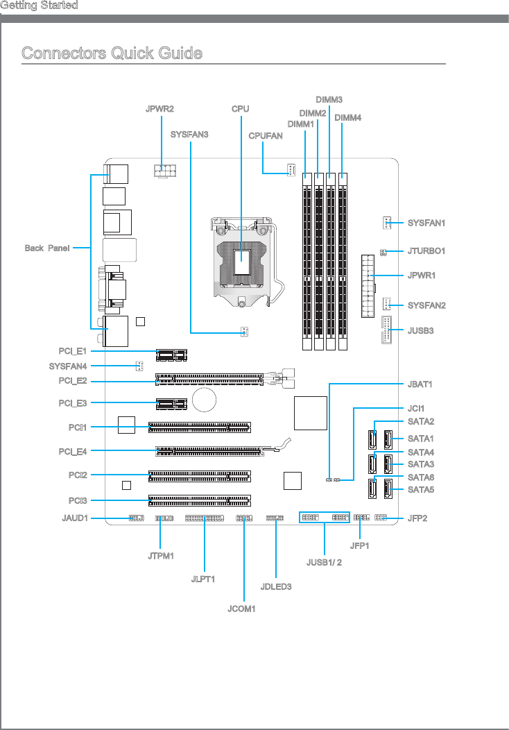
Connectors Quck Gude
Back Panel
CPU
CPUFAN
DIMM1
JPWR2
JPWR1
SATA2
JFP2
JAUD1
JCI1
JDLED3
PCI_E1
SYSFAN1
JBAT1
SYSFAN3
JCOM1
PCI_E2
PCI_E3
PCI_E4
JFP1
JTURBO1
JTPM1
JUSB3
JUSB1/ 2
SATA3
SATA5
JLPT1
BAT T
+
DIMM2
DIMM3
DIMM4
SYSFAN2
SYSFAN4
PCI1
PCI2
PCI3
SATA1
SATA4
SATA6
1-7
MS-7758
Chapter 1
Connectors Reference Gude
Port Name Port Type Page
Back Panel I/O Ports 1-8
CPU LGA 1155 CPU Socket 1-10
CPUFAN,SYSFAN1~4 Fan Power Connectors 1-23
DIMM1~4 DDR3 Memory Slots 1-16
JAUD1 Front Panel Audo Connector 1-27
JBAT1 Clear CMOS Jumper 1-30
JCI1 Chasss Intruson Connector 1-26
JCOM1 Seral Port Connector 1-28
JDLED3 Voce Gene Connector 1-29
JFP1, JFP2 Front Panel Connectors 1-24
JLPT1 Parallel Port Connector 1-28
JPWR1 ATX 24-pn Power Connector 1-15
JPWR2 ATX 8-pn Power Connector 1-15
JTPM1 TPM Module Connector 1-27
JTURBO1 MultConnect Panel Connector 1-29
JUSB1~2 USB 2.0 Expanson Connectors 1-26
JUSB3 USB 3.0 Expanson Connector 1-25
PCI_E1, E3 PCIe x1 Expanson Slots 1-18
PCI_E2, E4 PCIe x16 Expanson Slots 1-18
PCI1~3 PCI Expanson Slots 1-18
SATA1~6 SATA Connectors 1-22
1-8
Gettng Started
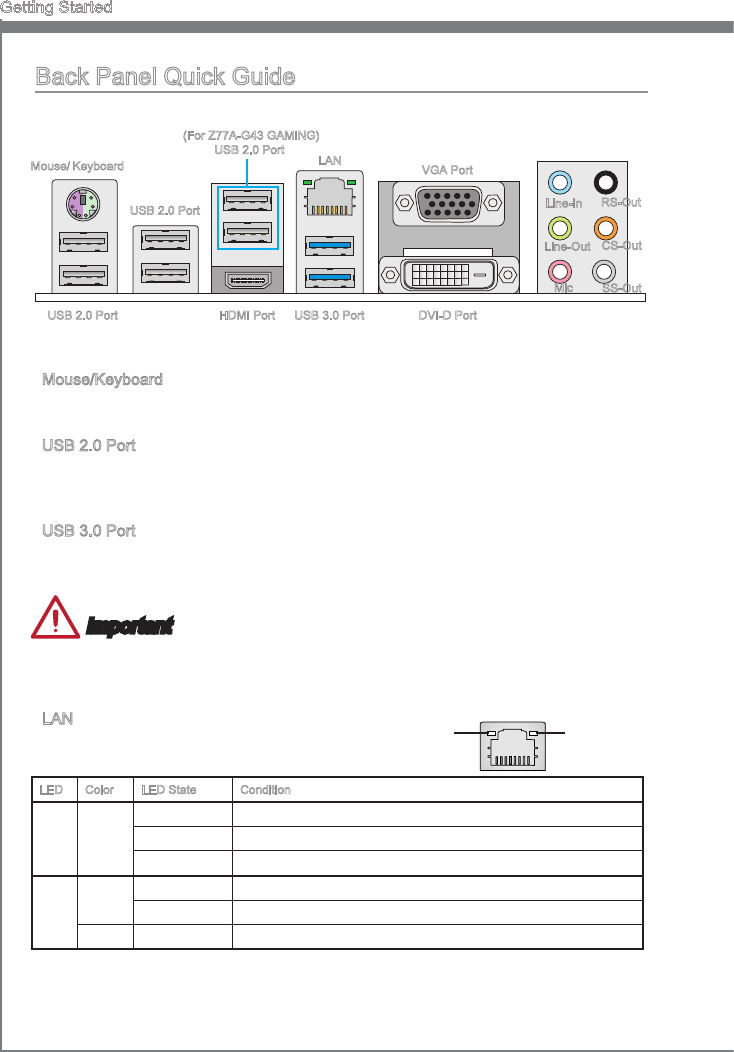
Mouse/Keyboard
A combnaton PS/2® mouse/keyboard DIN connector for a PS/2® mouse/keyboard.
USB 2.0 Port
The USB 2.0 port s for attachng USB 2.0 devces such as keyboard, mouse, or other
USB 2.0-compatble devces.
USB 3.0 Port
USB 3.0 port s backward-compatble wth USB 2.0 devces. It supports data transfer
rate up to 5 Gbt/s (SuperSpeed).
Important
In order to use USB 3.0 devces, you must connect to a USB 3.0 port. If a USB cable s
used, t must be USB 3.0 complant.
LAN
The standard RJ-45 LAN jack s for connectng to a
Local Area Network (LAN).
LED Color LED State Condton
Left Yellow O LAN lnk s not establshed.
On(Steady) LAN lnk s establshed.
On(ashng) The computer s communcatng wth another computer on the network.
Rght Green O 10 Mbts/sec data rate
On 100 Mbts/sec data rate
Orange On 1000 Mbts/sec data rate
▶
▶
▶
▶Yellow Green/ Orange
Back Panel Quck Gude
Lne-In
Lne-Out
Mc
RS-Out
CS-Out
SS-Out
USB 3.0 Port
LAN
Mouse/ Keyboard
USB 2.0 Port
USB 2.0 Port
VGA Port
DVI-D PortUSB 2.0 Port HDMI Port
(For Z77A-G43 GAMING)
1-9
MS-7758
Chapter 1
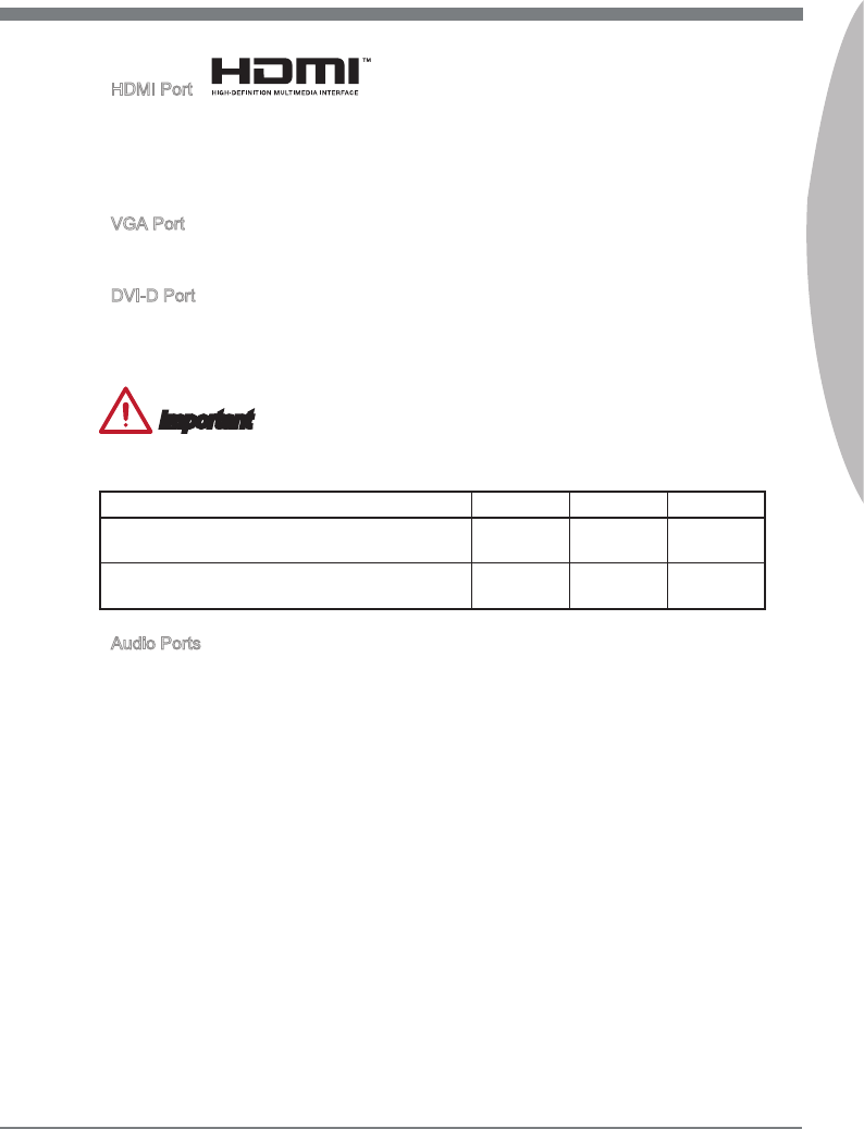
HDMI Port
The Hgh-Denton Multmeda Interface (HDMI) s an all-dgtal audo-vdeo nterface
that s capable of transmttng uncompressed streams. HDMI supports all types of TV
formats, ncludng standard, enhanced, or hgh-denton vdeo, plus mult-channel
dgtal audo on a sngle cable.
VGA Port
The DB15-pn female connector s provded for montor.
DVI-D Port
The DVI-D (Dgtal Vsual Interface- Dgtal) connector can be connected to a LCD
montor, or a CRT montor wth an adapter. To connect a montor, please refer to the
montor’s manual for more nformaton.
Important
Ths manboard supports dual-dsplay functon by any two output ports (HDMI+DVI-D,
DVI-D+VGA or VGA+HDMI).
HDMI+DVI-D DVI-D+VGA VGA+HDMI
Extend mode
(Extend the desktop to the second montor) ◯ ◯ ◯
Clone mode
(Two montors have the same screen) ◯ ◯ ◯
Audo Ports
These connectors are used for audo devces. The color of the jack refers to the functon
of the connector.
Blue-Lne n: Used for connectng external audo outputtng devces.
Green- Lne out: Used as a connector for speakers or headphone.
Pnk- Mc: Used as a connector for a mcrophone.
Black- RS-Out: Rear surround sound lne out n 4/ 5.1/ 7.1 channel mode.
Orange- CS-Out: Center/ subwoofer lne out n 5.1/ 7.1 channel mode.
Gray- SS-Out: Sde surround sound lne out n 7.1 channel mode.
▶
▶
▶
▶
■
■
■
■
■
■
1-10
Gettng Started
CPU (Central Processng Unt)
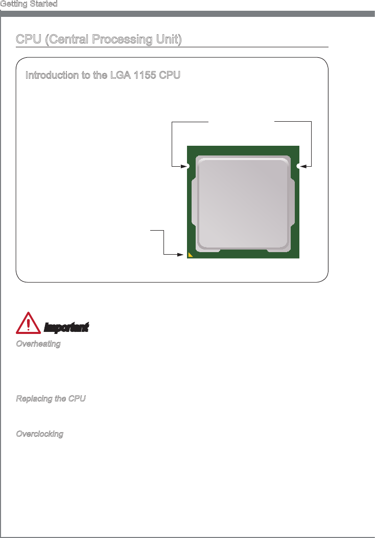
Introducton to the LGA 1155 CPU
The surface of the LGA 1155 CPU
has two algnment keys and a
yellow trangle to assst n correctly
lnng up the CPU for manboard
placement. The yellow trangle s the
Pn 1 ndcator.
Yellow trangle s the
Pn 1 ndcator
Algnment Key
Important
Overheatng
Overheatng can serously damage the CPU and manboard. Always make sure the
coolng fans work properly to protect the CPU from overheatng. Be sure to apply an
even layer of thermal paste (or thermal tape) between the CPU and the heatsnk to
enhance heat dsspaton.
Replacng the CPU
When replacng the CPU, always turn o the system’s power supply and unplug the
power supply’s power cord to ensure the safety of the CPU.
Overclockng
Ths manboard s desgned to support overclockng. Before attemptng to overclock,
please make sure that all other system components can tolerate overclockng. Any
attempt to operate beyond product speccatons s not recommend. MSI does not
guarantee the damages or rsks caused by nadequate operaton beyond product
speccatons.
1-11
MS-7758
Chapter 1
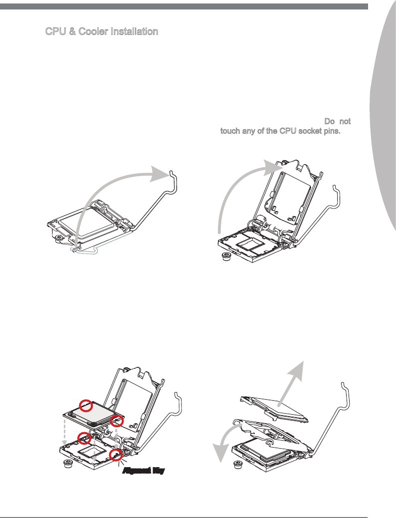
CPU & Cooler Installaton
When nstallng a CPU, always remember to nstall a CPU cooler. A CPU cooler s
necessary to prevent overheatng and mantan system stablty. Follow the steps below
to ensure correct CPU and CPU cooler nstallaton. Wrong nstallaton can damage both
the CPU and the manboard.
Unhook and lft the loadng lever to
the fully open poston.
1. The loadng plate should automatcally
lft up as the loadng lever s pushed
to the fully open poston. Do not
touch any of the CPU socket pns.
2.
Lne up the CPU to t the CPU
socket. Be sure to hold the CPU by
the base wth the metal contacts
facng downward. The algnment
keys on the CPU wll lne up wth the
edges of the CPU socket to ensure a
correct t.
3. Close the loadng plate and remove
the plastc protectve cap.
4.
Algnment Key
1-12
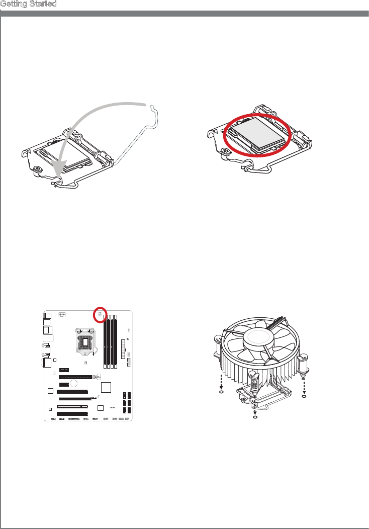
Gettng Started
Inspect the CPU to check f t s
properly seated n the socket. Press
the loadng lever down and lock t
under the retenton tab.
5. Evenly spread a thn layer of
thermal paste (or thermal tape) on
the top of the CPU. Ths wll help n
heat dsspaton and prevent CPU
overheatng.
6.
Locate the CPU fan connector on the
manboard.
7. Place the heatsnk on the manboard
wth the fan’s wres facng towards the
fan connector and the hooks matchng
the holes on the manboard.
8.
BATT
+
1-13
MS-7758
Chapter 1
Important
Do not touch the CPU socket pns.
Conrm that the CPU cooler has formed a tght seal wth the CPU before bootng
your system.
Whenever the CPU s not nstalled, always protect the CPU socket pns by coverng
the socket wth the plastc cap.
Please refer to the documentaton n the CPU cooler package for more detals about
CPU cooler nstallaton.
•
•
•
•
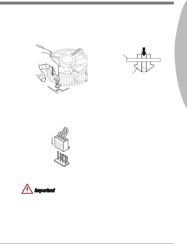
Push down on the heatsnk untl the
four clps get wedged nto the holes
on the manboard. Press the four
hooks down to fasten the cooler. As
each hook locks nto poston a clck
should be heard.
9. Inspect the manboard to ensure that
the clp-ends have been properly
locked n place.
10.
Fnally, attach the CPU fan cable
to the CPU fan connector on the
manboard.
11.
Manboard
Hook
1-14
Gettng Started
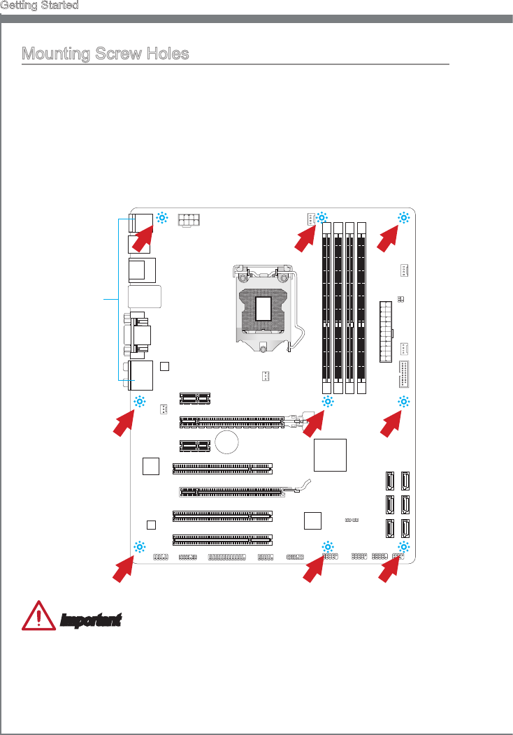
Mountng Screw Holes
When nstallng the manboard, rst nstall the necessary mountng stands requred for
a manboard on the mountng plate n your computer case. If there s an I/O back plate
that came wth the computer case, please replace t wth the I/O backplate that came
wth the manboard package. The I/O backplate should snap easly nto the computer
case wthout the need for any screws. Algn the mountng plate’s mountng stands wth
the screw holes on the manboard and secure the manboard wth the screws provded
wth your computer case. The locatons of the screw holes on the manboard are shown
below. For more nformaton, please refer to the manual that came wth the computer
case.
Important
Install the manboard on a at surface free from unnecessary debrs.
To prevent damage to the manboard, any contact between the manboard crcutry
and the computer case, except for the mountng stands, s prohbted.
Please make sure there are no loose metal components on the manboard or wthn
the computer case that may cause a short crcut of the manboard.
•
•
•
The I/O ports should be facng toward
the rear of the computer case. They
should lne up wth the holes on the
I/O backplate.
BAT T
+
1-15
MS-7758
Chapter 1
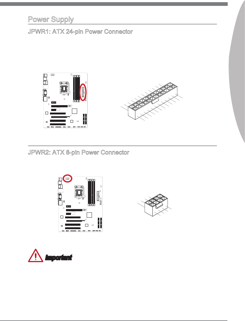
Power Supply
JPWR1: ATX 24-pn Power Connector
Ths connector allows you to connect an ATX 24-pn power supply. To connect the ATX
24-pn power supply, algn the power supply cable wth the connector and rmly press
the cable nto the connector. If done correctly, the clp on the power cable should be
hooked on the manboard’s power connector.
BATT
+
13.+3.3V
1.+3.3V
14.-12V
2.+3.3V
15.Ground
3.Ground
16.PS-ON#
4.+5V17.Ground
5.Ground
18.Ground
6.+5V
19.Ground
7.Ground
22.+5V
10.+12V
20.Res
8.PWR OK
23.+5V
11.+12V
21.+5V
9.5VSB
24.Ground
12.+3.3V
JPWR2: ATX 8-pn Power Connector
Ths connector provdes 12V power to the CPU.
7.+12V
3.Ground
5.+12V
1.Ground
8.+12V
4.Ground
6.+12V
2.Ground
BATT
+
Important
Make sure that all the power cables are securely connected to a proper ATX power sup-
ply to ensure stable operaton of the manboard.
1-16
Gettng Started
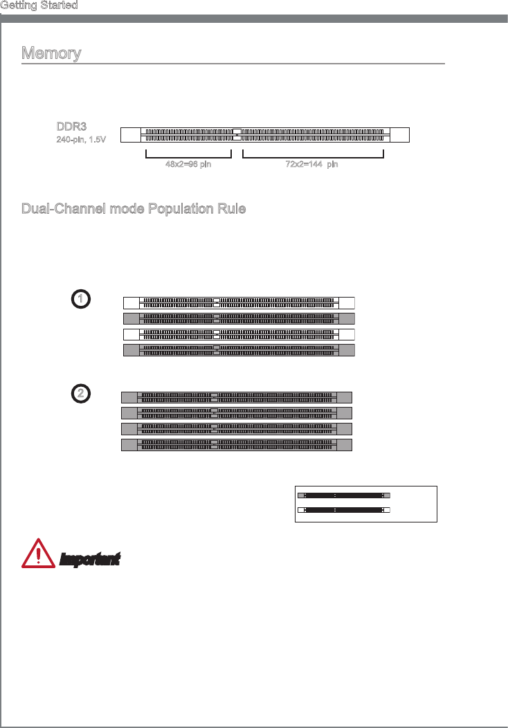
Memory
These DIMM slots are used for nstallng memory modules. For more nformaton on
compatble components, please vst http://www.ms.com/servce/test-report
DDR3
240-pn, 1.5V
48x2=96 pn 72x2=144 pn
Dual-Channel mode Populaton Rule
In Dual-Channel mode, the memory modules can transmt and receve data wth two
data bus channels smultaneously. Enablng Dual-Channel mode can enhance system
performance. The followng llustratons explan the populaton rules for Dual-Channel
mode.
1 DIMM1
DIMM2
DIMM3
DIMM4
2 DIMM1
DIMM2
DIMM3
DIMM4
Important
DDR3 memory modules are not nterchangeable wth DDR2, and the DDR3 standard
s not backward compatble. Always nstall DDR3 memory modules n DDR3 DIMM
slots.
To ensure system stablty, memory modules must be of the same type and densty
n Dual-Channel mode.
Due to chpset resource usage, the system wll only detect up to 31+ GB of memory
(not full 32 GB) when all DIMM slots have 8GB memory modules nstalled.
•
•
•
Installed
Empty
1-17
MS-7758
Chapter 1
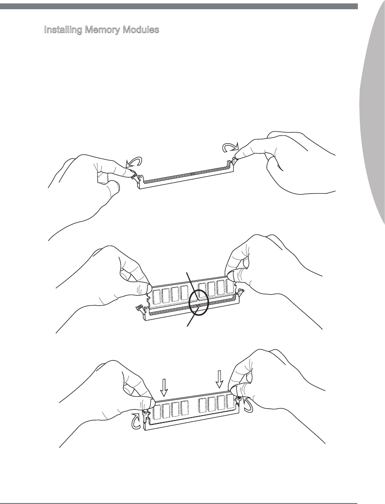
Installng Memory Modules
Unlock the DIMM slot by pushng the mountng clps to the sde. Vertcally nsert the
memory module nto the DIMM slot. The memory module has an o-center notch on
the bottom that wll only allow t to t one way nto the DIMM slot.
Push the memory module deep nto the DIMM slot. The plastc clps at each sde
of the DIMM slot wll automatcally close when the memory module s properly seat
and an audble clck should be heard.
Manually check f the memory module has been locked n place by the DIMM slot’s
sde clps.
1.
2.
3.
Notch
Volt
1-18
Gettng Started
Expanson Slots
Ths manboard contans numerous ports for expanson cards, such as dscrete graphcs
or audo cards.
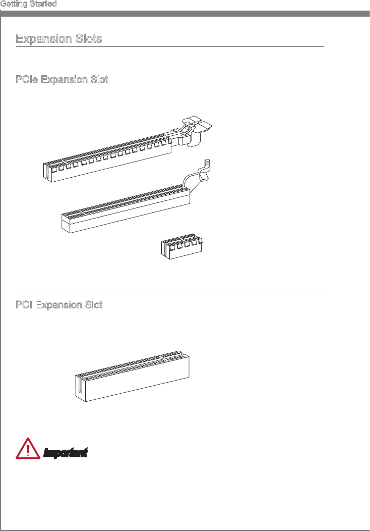
PCIe Expanson Slot
The PCIe slot supports the PCIe nterface expanson card.
PCIe 2.0 x16 Slot
PCIe 2.0 x1 Slot
PCIe 3.0 x16 Slot
PCI Expanson Slot
The PCI slot supports addtonal LAN, SCSI, USB, and other add-on cards that comply
wth PCI speccatons.
32-bt PCI Slot
Important
When addng or removng expanson cards, always turn o the power supply and
unplug the power supply power cable from the power outlet. Read the expanson card’s
documentaton to check for any necessary addtonal hardware or software changes.
1-19
MS-7758
Chapter 1
PCI Interrupt Request Routng
IRQ, or nterrupt request lnes, are hardware lnes over whch devces can send nterrupt
requests to the processor. The PCI IRQ pns are typcally connected to the PCI bus pns
as followed:
Order1 Order2 Order3 Order4
PCI Slot1 INT A# INT B# INT C# INT D#
PCI Slot2 INT B# INT C# INT D# INT A#
PCI Slot3 INT C# INT D# INT A# INT B#
Vdeo/ Graphcs Cards
If avalable, ths manboard takes advantage of the CPU’s ntegrate graphcs processor,
but dscrete vdeo cards can be nstalled by way of the manboard’s expanson slots.
Addng on one or more dscrete vdeo cards wll sgncantly boost the system’s graphcs
performance. For best compatblty, MSI graphcs cards are recommended.
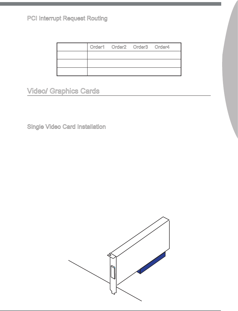
Sngle Vdeo Card Installaton
Determne what type of expanson slot(s) the vdeo card wll use. Locate the expan-
son slot(s) on the manboard. Remove any protectve expanson slot covers from
the computer case.
Lne up the vdeo card on top of the expanson slot(s) wth the dsplay ports facng
out of the computer case. For a sngle vdeo card nstallaton, usng the PCI_E2 slot
s recommended.
Push the vdeo card nto ts expanson slot(s). Dependng on the expanson slot(s)
used, there should be clp(s) on the expanson slot(s) that wll lock n place.
If needed, screw the edge of the graphcs card to the computer case. Some vdeo
cards mght requre a power cable drectly from the power supply.
Please consult your vdeo card’s manual for further nstructons regardng drver
nstallaton or other specal settngs.
1.
2.
3.
4.
5.
1-20
Gettng Started
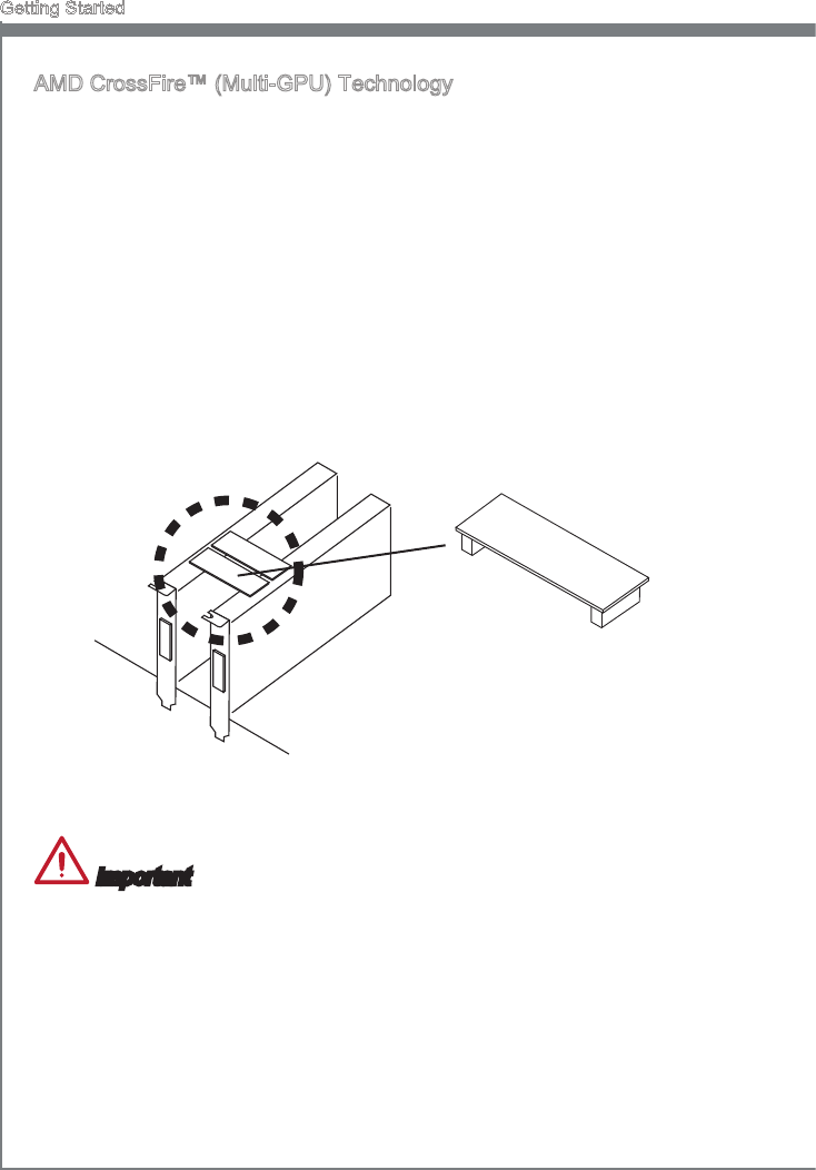
AMD CrossFre™ (Mult-GPU) Technology
AMD CrossFre™ s a mult-GPU performance gamng platform. By lnkng together
two or more dscrete GPUs, CrossFre™ can sgncant mprove system graphcs
performance. It allows the ablty to scale a system’s graphcs power as needed,
makng t the most scalable gamng platform. Ths manboard wll automatcally
detect CrossFre™ technology and make changes n the BIOS as needed. Follow the
nstructons below to ensure a successful two-way CrossFre™ nstallaton.
Install two AMD Radeon™ HD graphcs cards nto both PCIe x16 expanson slots.
Wth the two cards nstalled, two CrossFre™ Vdeo Lnk cable are requred to con-
nect the graphcs cards. Attach one sde of the cable on each of the cards by way
of the metal contacts (please refer to the pcture below). Please note that although
two graphcs cards have been nstalled, only the dsplay ports on the graphcs card
nstalled n the rst PCIe x16 slot wll work. All dsplays should be connected to ths
graphcs card.
1.
2.
CrossFreTM Vdeo Lnk cable
Important
Please ensure that all graphcs cards used n CrossFre™ mode are of the same
brand and speccatons. For best compatblty wth the manboard, MSI graphcs
cards are recommended.
Make sure to connect an adequate power supply to the power connectors on the
graphcs cards to ensure stable operaton.
Only Wndows XP wth Servce Pack 2 (SP2), Wndows XP Professonal x64 Edton,
Wndows 7 & Wndows 8 wll support CrossFre mode.
•
•
•
1-21
MS-7758
Chapter 1
Boot up the computer and nstall the drvers and software ncluded n your vdeo
card package. For more nformaton, please refer to the manual that came wth your
vdeo card.
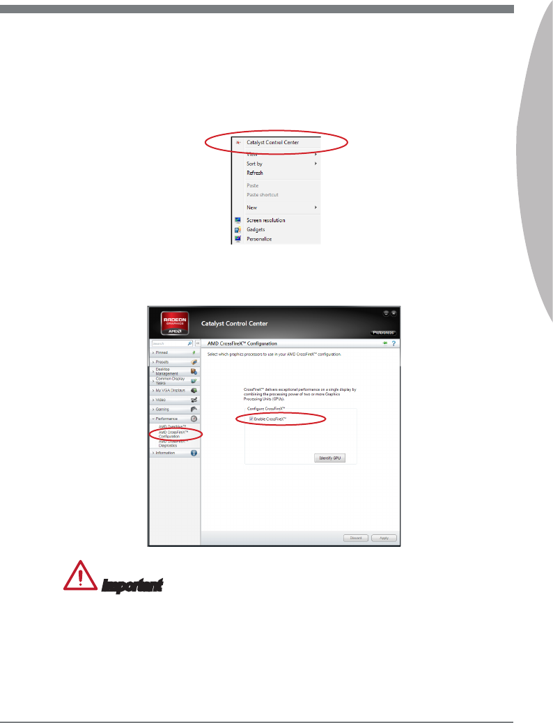
After all of the hardware and software has been properly nstalled, reboot the sys-
tem. After enterng the operatng system (OS), rght clck on the desktop and choose
the “Catalyst Control Center”.
3.
4.
The CrossFre™ settng must be enabled to allow CrossFre™ mode to operate.
The followng screen appears n the Catalyst Control Center. Dependng on your
operatng system, the screen may look derent.
5.
Important
A CrossFre
TM
system has four possble dsplay modes:
SuperTlng
Scssor Mode
Alternate Frame Renderng
Super Ant-alasng.
For more detals, please consult the graphcs card manual.
•
•
•
•
1-22
Gettng Started
Internal Connectors
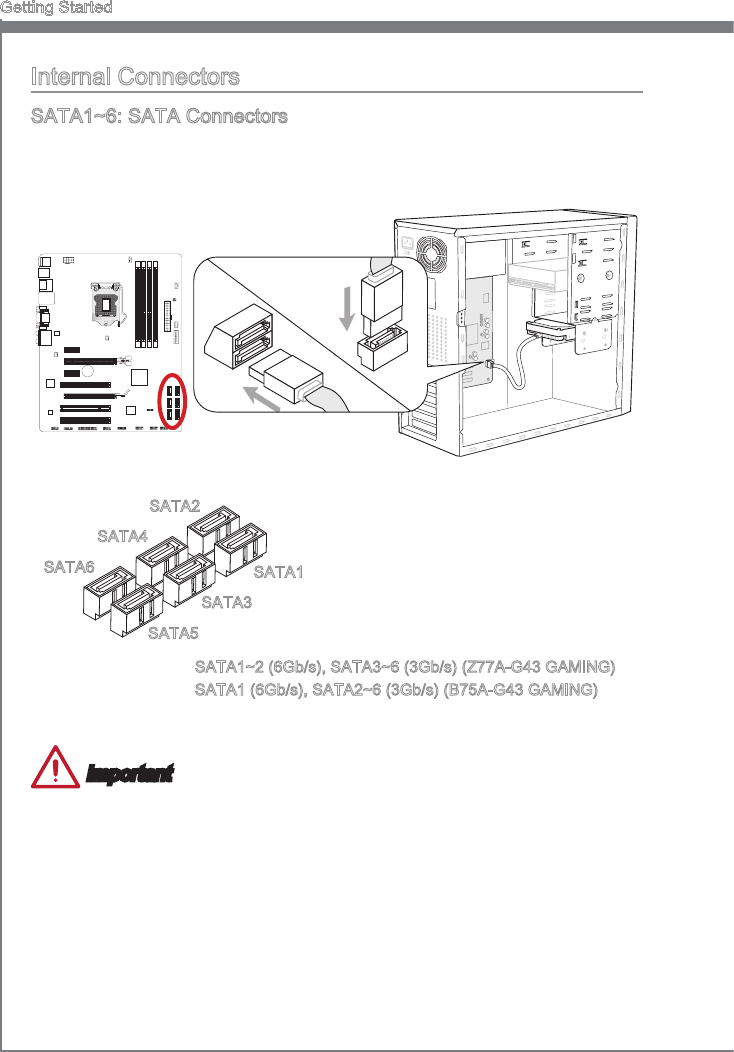
SATA1~6: SATA Connectors
Ths connector s a hgh-speed SATA nterface port. Each connector can connect to one
SATA devce. SATA devces nclude dsk drves (HDD), sold state drves (SSD), and
optcal drves (CD/ DVD/ Blu-Ray).
* The MB layout n ths gure s for reference only.
SATA1~2 (6Gb/s), SATA3~6 (3Gb/s) (Z77A-G43 GAMING)
BATT
+
SATA1
SATA2
SATA3
SATA4
SATA5
SATA6
SATA1 (6Gb/s), SATA2~6 (3Gb/s) (B75A-G43 GAMING)
Important
Many SATA devces also need a power cable from the power supply. Such devces
nclude dsk drves (HDD), sold state drves (SSD), and optcal drves (CD / DVD /
Blu-Ray). Please refer to the devce’s manual for further nformaton.
Many computer cases also requre that large SATA devces, such as HDDs, SSDs,
and optcal drves, be screwed down nto the case. Refer to the manual that came
wth your computer case or your SATA devce for further nstallaton nstructons.
Please do not fold the SATA cable at a 90-degree angle. Data loss may result durng
transmsson otherwse.
SATA cables have dentcal plugs on ether sdes of the cable. However, t s recom-
mended that the at connector be connected to the motherboard for space savng
purposes.
•
•
•
•
1-23
MS-7758
Chapter 1
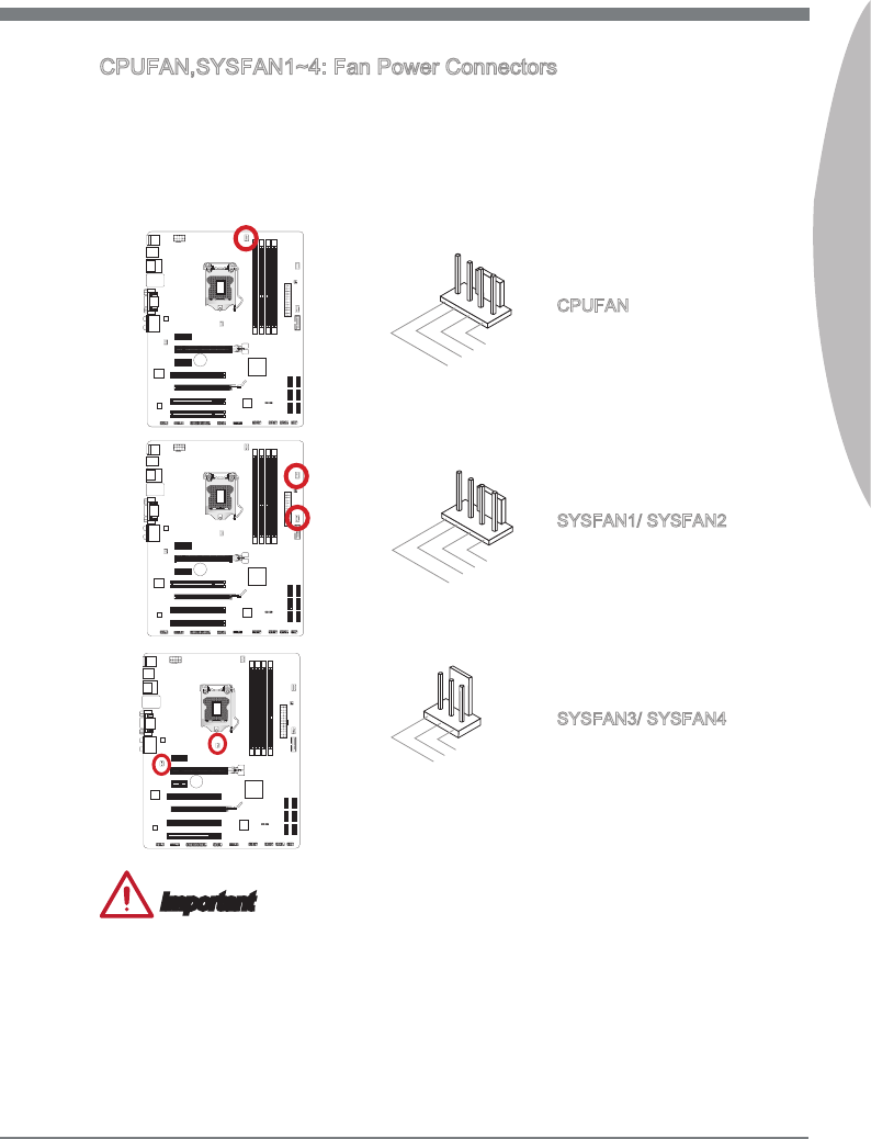
CPUFAN,SYSFAN1~4: Fan Power Connectors
The fan power connectors support system coolng fans wth +12V. If the motherboard
has a System Hardware Montor chpset on-board, you must use a specally desgned
fan wth a speed sensor to take advantage of the CPU fan control. Remember to
connect all system fans. Some system fans may not connect to the motherboard and
wll nstead connect to the power supply drectly. A system fan can be plugged nto any
avalable system fan connector.
BATT
+
BATT
+
BATT
+
SYSFAN3/ SYSFAN4
1.Ground
2.+12V
3.No Use
1.Ground
2.+12V
3.Sensor
4.Control
CPUFAN
1.Ground
2.+12V
3.Sensor
4.No Use
SYSFAN1/ SYSFAN2
Important
Please refer to your processor’s ocal webste or consult your vendor to nd recom-
mended CPU coolng fans.
The CPUFAN, SYSFAN1, SYSFAN2 connectors support Smart Fan Control wth
lner mode. The Control Center II utlty can be nstalled to automatcally control the
fan speeds accordng to the CPU’s and system’s temperature.
If there are not enough ports on the motherboard to connect all system fans, adapters
are avalable to connect a fan drectly to a power supply.
Before rst boot up, ensure that there are no cables mpedng any fan blades.
•
•
•
•
1-24
Gettng Started
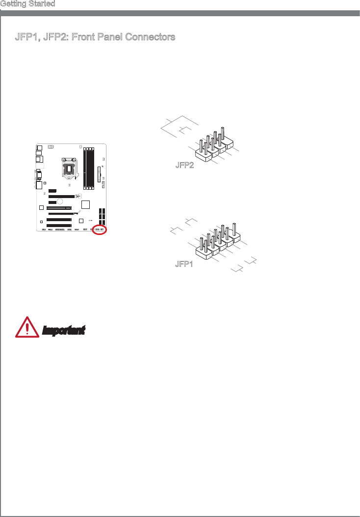
JFP1, JFP2: Front Panel Connectors
These connectors connect to the front panel swtches and LEDs. The JFP1 connector
s complant wth the Intel® Front Panel I/O Connectvty Desgn Gude. When nstallng
the front panel connectors, please use the optonal mConnectors to smplfy nstallaton.
Plug all the wres from the computer case nto the mConnectors and then plug the
mConnectors nto the motherboard.
BATT
+
1.+
3.-
10.No Pin
5.-Reset Switch
HDD LED
Power Switch
Power LED
7.+
9.Reserved
8.-
6.+
4.-
2.+
JFP1
1.Ground
3.Suspend LED
5.Power LED
7.No Pin
8.+
6.-
4.+
2.-
Buzzer
Speaker
JFP2
Important
On the connectors comng from the case, pns marked by small trangles are postve
wres. Please use the dagrams above and the wrtng on the mConnectors to
determne correct connector orentaton and placement.
The majorty of the computer case’s front panel connectors wll prmarly be plugged
nto JFP1.
•
•
1-25
MS-7758
Chapter 1
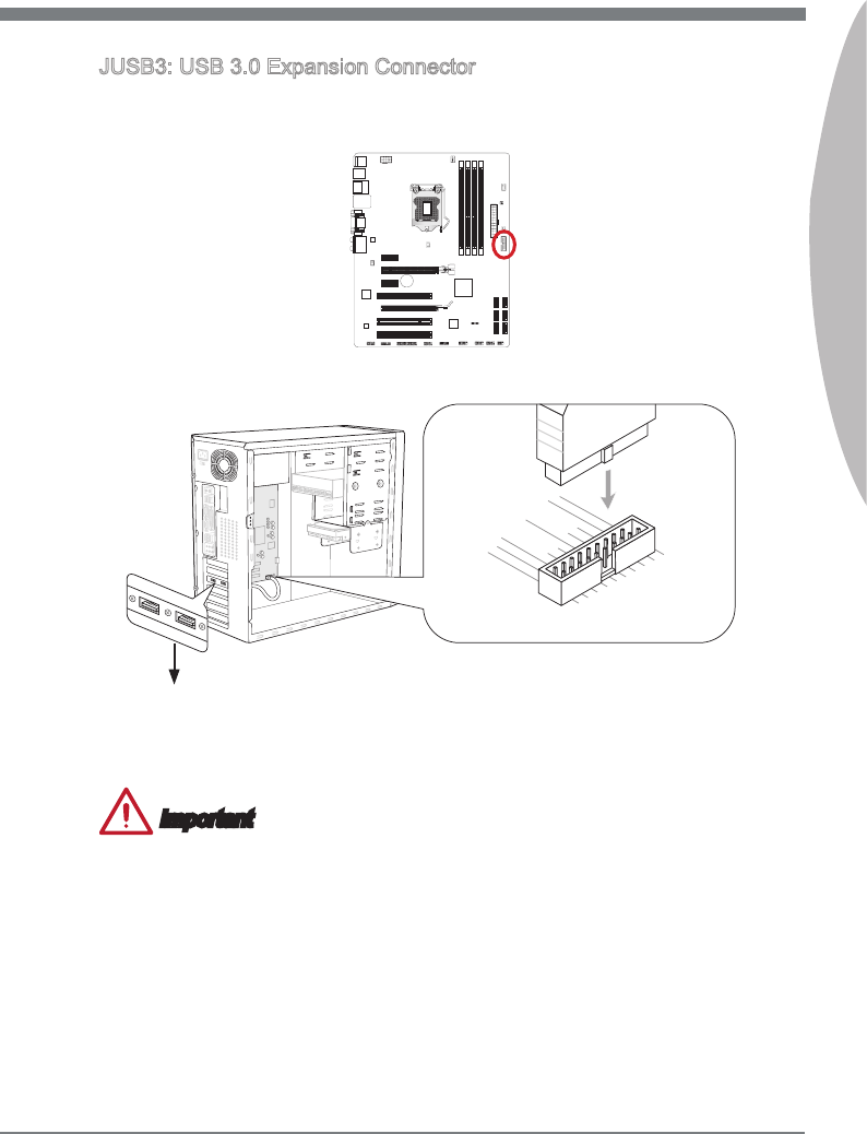
JUSB3: USB 3.0 Expanson Connector
The USB 3.0 port s backwards compatble wth USB 2.0 devces. It supports data
transfer rates up to 5Gbts/s (SuperSpeed).
115V
5.
USB3_TX_C_DN
4.Ground
3.USB3_RX_DP
2.USB3_RX_DN
1.Power
10.Ground
9. +
USB2.0
8.-
USB2.0
7.Ground
6.USB3_TX_C_DP
20.No Pin
19.Power
18.USB3_RX_DN
17.USB3_RX_DP
16.Ground
15.USB3_TX_C_DN
14.USB3_TX_C_DP
13.Ground
12.USB2.0-
11. +
USB2.0
* The MB layout n ths gure s for reference only.
USB 3.0 Bracket (optonal)
BATT
+
Important
Note that the VCC and GND pns must be connected correctly to avod possble
damage.
To use a USB 3.0 devce, you must connect the devce to a USB 3.0 port through an
optonal USB 3.0 complant cable.
•
•
1-26
Gettng Started
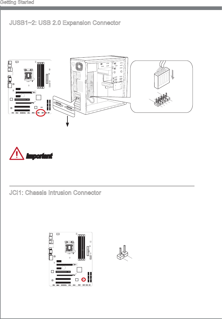
JUSB1~2: USB 2.0 Expanson Connector
Ths connector s desgned for connectng hgh-speed USB perpherals such as USB
HDDs, dgtal cameras, MP3 players, prnters, modems, and many others.
BATT
+
115V
1.VCC
3.USB0-
10.NC
5.USB0+
7.Ground
9.No Pin
8.Ground
6.USB1+
4.USB1-
2.VCC
* The MB layout n ths gure s for reference only.
USB 2.0 Bracket (optonal)
Important
Note that the VCC and GND pns must be connected correctly to avod possble dam-
age.
JCI1: Chasss Intruson Connector
Ths connector connects to the chasss ntruson swtch cable. If the computer case s
opened, the chasss ntruson mechansm wll be actvated. The system wll record ths
ntruson and a warnng message wll ash on screen. To clear the warnng, you must
enter the BIOS utlty and clear the record.
BATT
+
1.CINTRU
2.Ground
1-27
MS-7758
Chapter 1
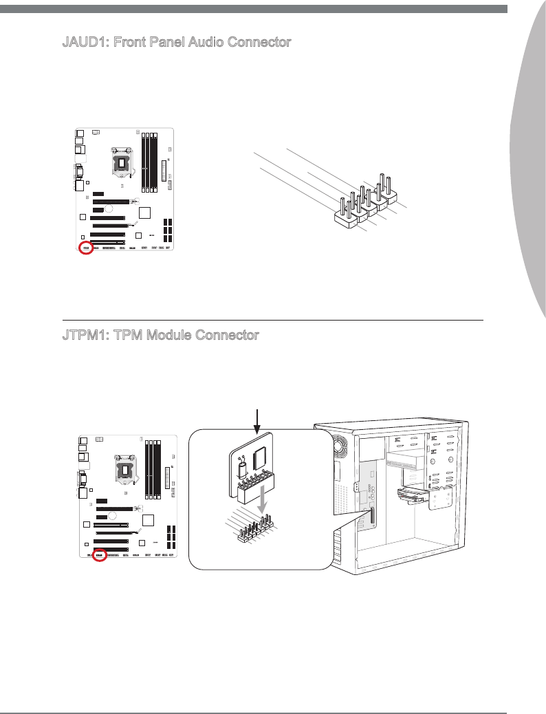
JAUD1: Front Panel Audo Connector
Ths connector allows you to connect the front audo panel located on your computer
case. Ths connector s complant wth the Intel® Front Panel I/O Connectvty Desgn
Gude.
BATT
+
1.MIC L
3.MIC R
10.Head Phone Detection
5.Head Phone R
7.SENSE_SEND
9.Head Phone L
8.No Pin
6.MIC Detection
4.NC
2.Ground
JTPM1: TPM Module Connector
Ths connector connects to a TPM (Trusted Platform Module). Please refer to the TPM
securty platform manual for more detals and usages.
* The MB layout n ths gure s for reference only.
115V
10.No Pin
14.Ground
8.5V Power
12.Ground
6.Serial IRQ
4.3.3V Power
2.3V Standby power
1.LPCClock
3.LPCReset
5.LPCaddress&datapin0
7.LPCaddress&datapin1
9.LPCaddress&datapin2
11.LPC address&datapin3
13.LPCFrame
TPM module s optonal
BATT
+
1-28
Gettng Started
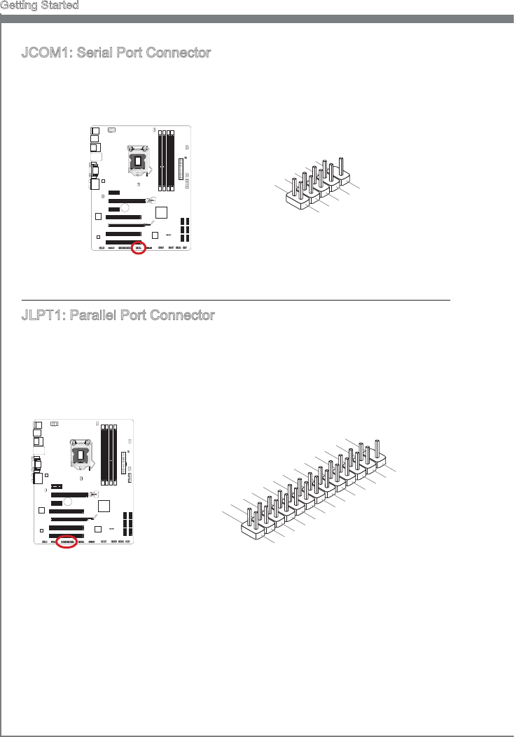
JCOM1: Seral Port Connector
Ths connector s a 16550A hgh speed communcaton port that sends/receves 16
bytes FIFOs. You can attach a seral devce.
BATT
+
1.DCD
3.SOUT
10.No Pin
5.Ground
7.RTS
9.RI
8.CTS
6.DSR
4.DTR
2.SIN
JLPT1: Parallel Port Connector
Ths connector s used to connect an optonal parallel port bracket. The parallel port
s a standard prnter port that supports Enhanced Parallel Port (EPP) and Extended
Capabltes Parallel Port (ECP) mode.
BATT
+
10.Ground
14.Ground
8.LPT_SLIN#
12.Ground
6.PINIT#
4.ERR#
2.AFD#
24.Ground
22.Ground
26.No Pin
20.Ground
18.Ground
16.Ground
1.RSTB#
3.PRND0
5.PRND1
7.PRND2
9.PRND3
11.PRND4
13.PRND5
15.PRND6
17.PRND7
19.ACK#
21.BUSY
23.PE
25.SLCT
1-29
MS-7758
Chapter 1
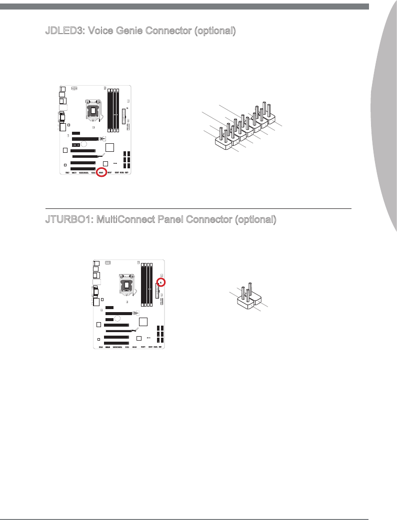
JDLED3: Voce Gene Connector (optonal)
Ths connector s used to lnk to the voce control module (optonal). Please refer to ts
user gude for more detals and usages.
BATT
+
10.No Pin
14.Reserved pin
8.Control pin
12.Reserved pin
6.VCC3
4.Control pin
2.Control pin 1.5VSB
3.Control pin
5.Control pin
7.Control pin
9.Ground
11.Reserved pin
13.Ground
JTURBO1: MultConnect Panel Connector (optonal)
Ths connector s used to connect an optonal front panel for controlng the OC Gene and
some addtonal functons. Please refer to ts user gude for more detals and usages.
BATT
+
3.TURBO
4.No Pin
2.Ground
1.TURBO
1-30
Gettng Started
Jumper
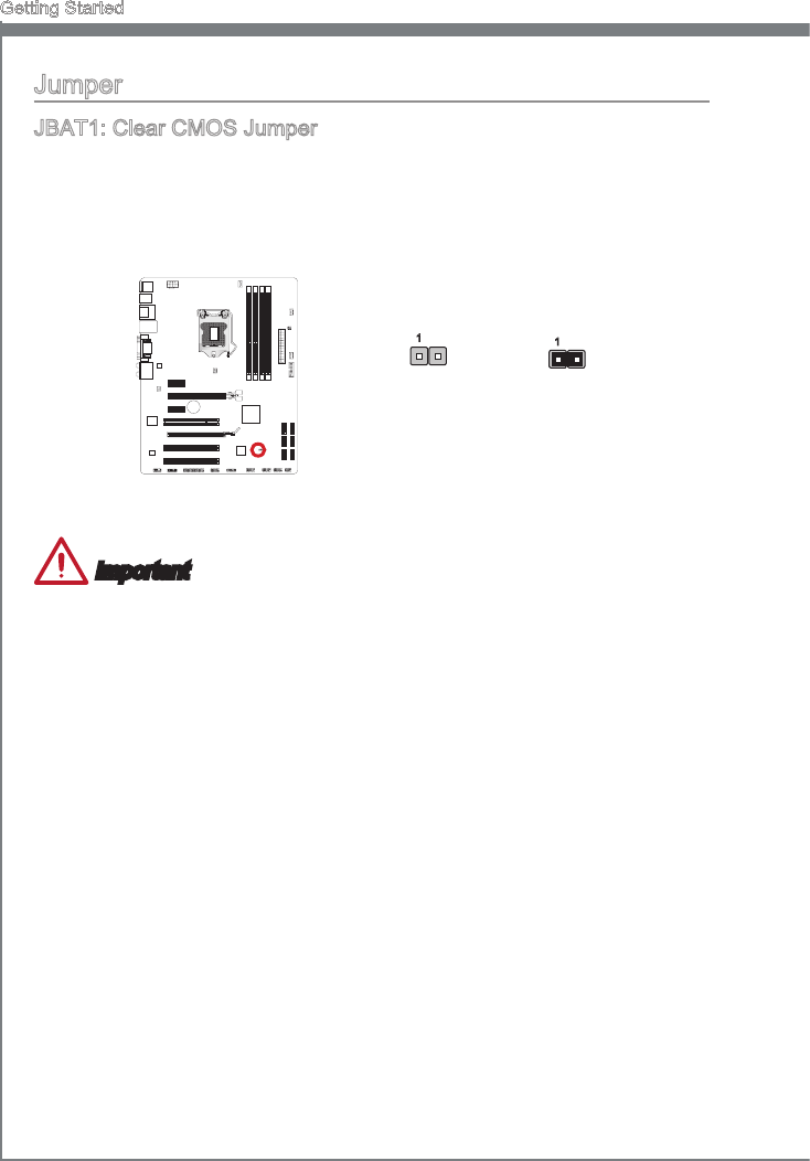
JBAT1: Clear CMOS Jumper
There s CMOS RAM onboard that s external powered from a battery located on the
motherboard to save system conguraton data. Wth the CMOS RAM, the system can
automatcally boot nto the operatng system (OS) every tme t s turned on. If you want
to clear the system conguraton, set the jumpers to clear the CMOS RAM.
BATT
+
Keep Data Clear Data
11
Important
You can clear the CMOS RAM by shortng ths jumper whle the system s o. Afterwards,
open the jumper . Do not clear the CMOS RAM whle the system s on because t wll
damage the motherboard.
1-31
MS-7758
Chapter 1
Drvers and Utltes
After you nstall the operatng system you wll need to nstall drvers to maxmze the
performance of the new computer you just bult. MSI manbaord comes wth a Drver
Dsc. Drvers allow the computer to utlze your manboard more ecently and take
advantage of any specal features we provde.
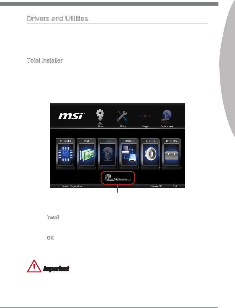
Total Installer
Total Installer s very easy to use and does a great job of ndng necessary drvers.
Please follow the steps below to nstall drvers and utltes for your new computer.
Insert MSI Drver Dsc nto the optcal drve. The setup screen wll automatcally
appear f autorun s enabled n OS.
Clck Total Installer. A popup dalog wll appear lstng all necessary drvers.
1.
2.
Select all checkbox on drver lstng dalog.
Clck Install button.
The software nstallaton wll then be n progress, after t has nshed t wll prompt
you to restart.
Clck OK button to nsh.
Restart your computer.
You can also use the same method to nstall the utltes.
Important
The pcture above s for reference only and may vary from the product you purchased.
Please refer to the actual screens of your system for detaled nformaton.
3.
4.
5.
6.
7.
Clck here


CLICK BIOS II s a revolutonary UEFI nterface that
allows you to setup and congure your system for
optmum use. Usng your mouse and keyboard, users can
change BIOS settngs, montor CPU temperature, select
the boot devce prorty and vew system nformaton
such as the CPU name, DRAM capacty, the OS verson
and the BIOS verson. Users can mport and export
parameter data for backup or for sharng wth frends. By
connectng to the Internet wthn CLICK BIOS II, users
can browse webpages, check mal and use Lve Update
n your system.
Chapter 2
BIOS Setup
2-2
BIOS Setup
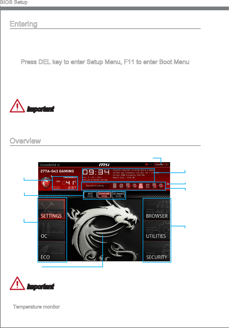
Enterng
Power on the computer and the system wll start the Power On Self Test (POST) pro-
cess. When the message below appears on the screen, please <DEL> key to enter
CLICK BIOS II:
Press DEL key to enter Setup Menu, F11 to enter Boot Menu
If the message dsappears before you respond and you stll need to enter CLICK BIOS
II, restart the system by turnng the computer OFF then back ON or pressng the RESET
button. You may also restart the system by smultaneously pressng <Ctrl>, <Alt>, and
<Delete> keys.
Important
The tems under each BIOS category descrbed n ths chapter are under contnuous
update for better system performance. Therefore, the descrpton may be slghtly der-
ent from the latest BIOS and should be held for reference only.
Overvew
After enterng CLICK BIOS II, the followng screen s dsplayed.
BIOS menu
selecton
Temperature
montor
System
nformaton
Boot devce
prorty bar
Menu dsplay
Boot menu
BIOS menu
selecton
Mode
selecton
Language
Important
The pctures n ths gude are for reference only and may vary from the product you pur-
chased. Please refer to the actual screens of your system for detaled nformaton.
Temperature montor
Ths block shows the temperature of the processor and the manboard.
▶
2-3
MS-7758
Chapter 2
System nformaton
Ths block shows the tme, date, CPU name, CPU frequency, DRAM frequency, DRAM
capacty and the BIOS verson.
BIOS menu selecton
The followng optons are avalable:
SETTINGS - Use ths menu to specfy your settngs for chpset features and
boot devces.
OC - Ths menu contans tems of the frequency and voltage adjustments. In-
creasng the frequency can get better performance, however hgh frequency
and heat can cause nstablty, we do not recommend general users to over-
clock.
ECO - Ths menu s related to energy-savng settngs.
BROWSER - Ths feature s used to enter the MSI Wnk web browser.
UTILITIES - Ths menu contans utltes for backup and update.
SECURITY - The securty menu s used to keep unauthorzed people from mak-
ng any changes to the settngs. You can use these securty features to protect
your system.
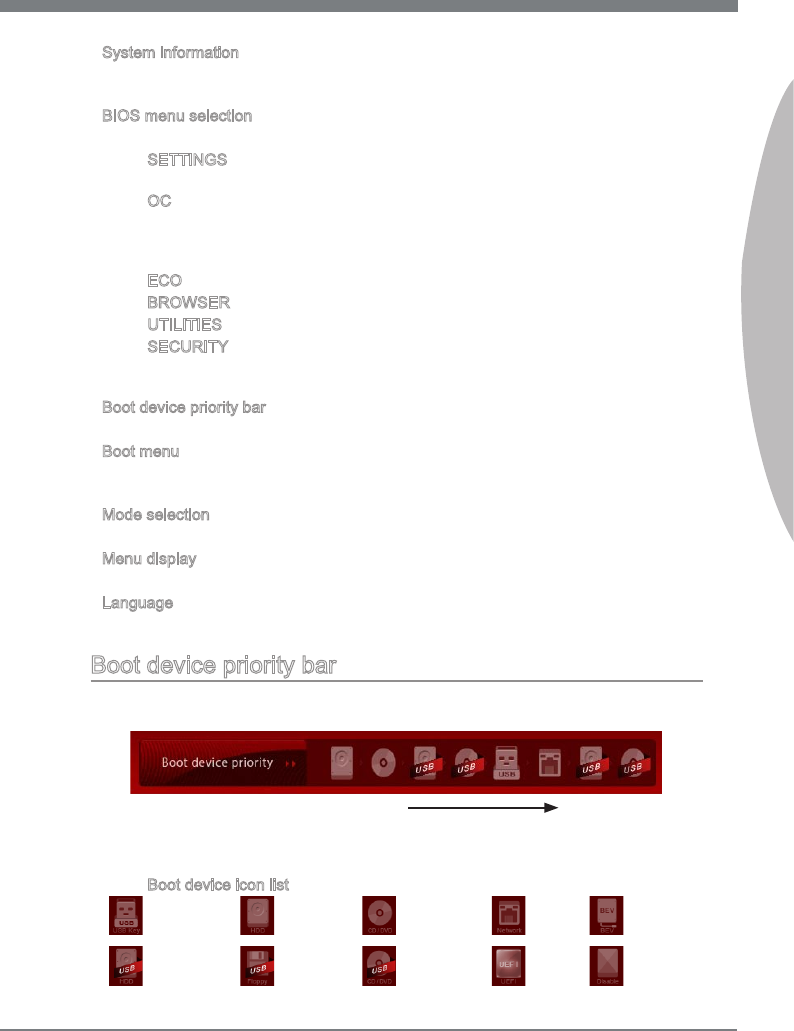
Boot devce prorty bar
You can move the devce cons to change the boot prorty.
Boot menu
Ths button s used to open a boot menu. Clck the tem to boot the system from the
devce nstantly.
Mode selecton
Ths feature allows you to load presets of energy savng or overclockng.
Menu dsplay
Ths area provdes BIOS settngs and nformaton to be congured.
Language
Ths allows you to select the language of the BIOS settng.
Boot devce prorty bar
Ths bar shows the prorty of the boot devces. The lghted cons ndcate that the
devces are avalable.
Hgh prorty Low prorty
Clck and draw the con to left or rght to specfy the boot prorty.
Boot devce con lst
Optcal
dsk
UEFI
USB
oppy
USB hard
dsk drve USB optcal
drve Dsable
BEVLAN
Hard dsk
drve
USB Drve
▶
▶
■
■
■
■
■
■
▶
▶
▶
▶
▶
■
2-4
BIOS Setup
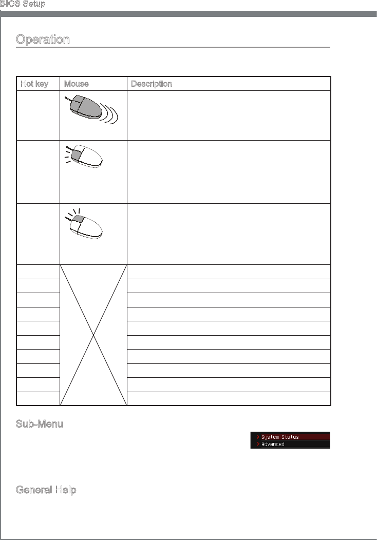
Operaton
CLICK BIOS II allows you to control BIOS settngs wth the mouse and the keyboard.
The followng table lsts and descrbes the hot keys and the mouse operatons.
Hot key Mouse Descrpton
<↑↓→← >
Move the cursor
Select Item
<Enter>
Clck/ Double-
clck the left
button
Select Icon/ Feld
<Esc>
Clck the rght
button
Jump to the Ext menu or return to the prevous from
a submenu
<+> Increase the numerc value or make changes
<-> Decrease the numerc value or make changes
<F1> General Help
<F4> CPU Speccatons
<F5> Enter Memory-Z
<F6> Load optmzed defaults
<F8> OC Prole Load From USB
<F9> OC Prole Save to USB
<F10> Save Change and Reset
<F12> Save a screenshot to a FAT/FAT32 USB drve
Sub-Menu
If you nd a pont symbol to the left of certan elds, that means
a sub-menu can be launched for addtonal optons. You can use
the arrow keys or mouse to hghlght the eld and press <Enter> or double-clck the left
mouse button to enter the sub-menu. If you want to return to the prevous menu, just
press <Esc> or clck the rght mouse button.
General Help
The General Help screen lsts the approprate keys to use for navgaton. You can call
up ths screen from any menu by smply pressng <F1>. Press <Esc> to ext the Help
screen.
2-5
MS-7758
Chapter 2
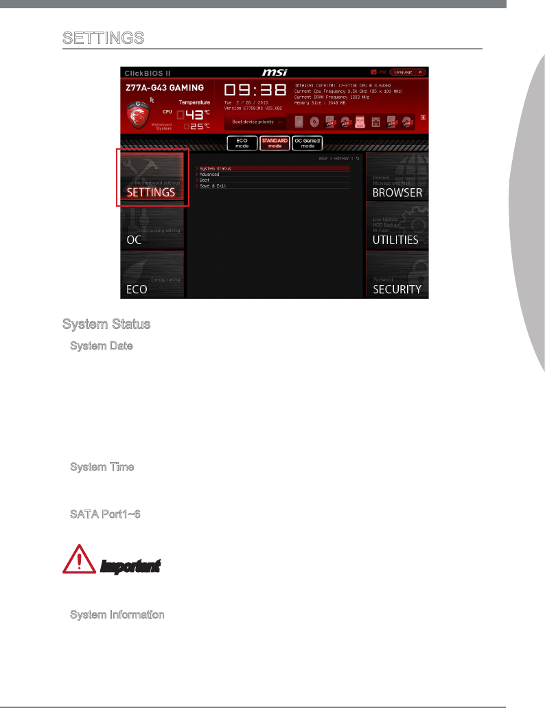
SETTINGS
System Status
System Date
Ths allows you to set the system date that you want (usually the current date).
The format s <day> <month> <date> <year>.
day Day of the week, from Sun to Sat, determned by BIOS.
Read-only.
month The month from Jan. through Dec.
date The date from 1 to 31 can be keyed by numerc functon keys.
year The year can be adjusted by users.
System Tme
Ths allows you to set the system tme that you want (usually the current tme). The tme
format s <hour> <mnute> <second>.
SATA Port1~6
Shows devces connected to specc SATA ports.
Important
If your devce s not dsplayed, turn o computer and re-check SATA cable and power
cable connectons to the devce.
System Informaton
Shows detaled system nformaton, ncludng CPU type, BIOS verson, and Memory
(read only).
▶
▶
▶
▶
2-6
BIOS Setup
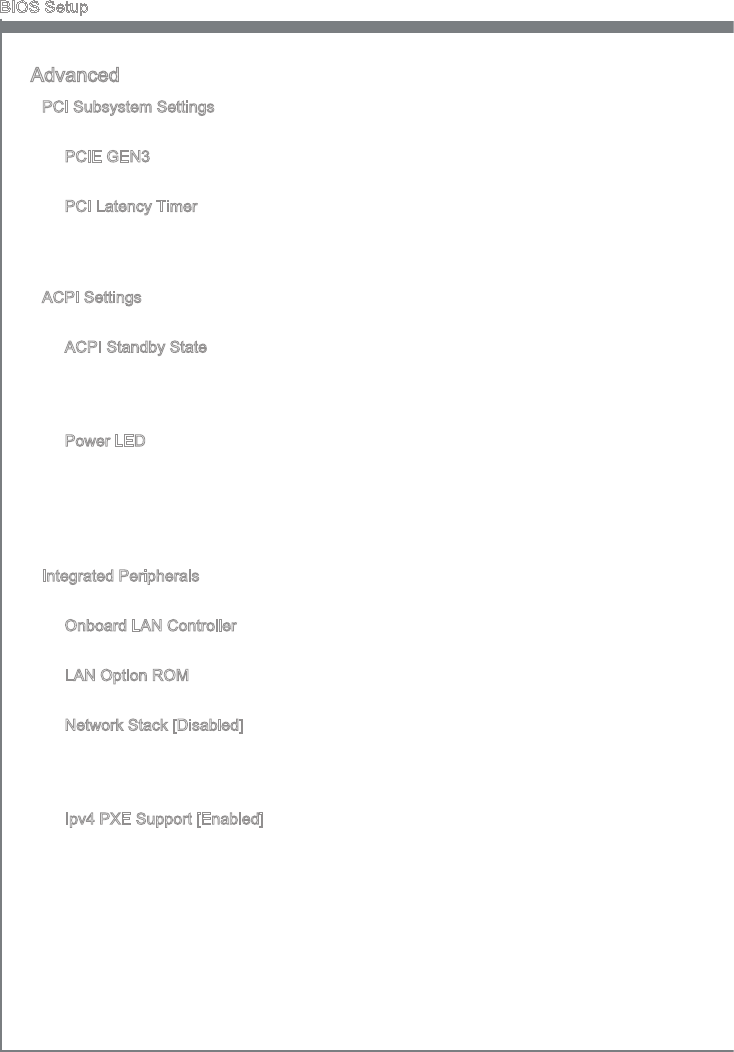
Advanced
PCI Subsystem Settngs
Press <Enter> to enter the sub-menu.
PCIE GEN3
Ths tem s used to enable/ dsable the PCIe generaton 3 support.
PCI Latency Tmer
Controls how long each PCI devce can hold the bus before another takes over.
When set to hgher values, every PCI devce can conduct transactons for a longer
tme and thus mprove the eectve PCI bandwdth.
ACPI Settngs
Press <Enter> to enter the sub-menu.
ACPI Standby State
Speces the power savng mode for ACPI functon
[S1] Sleep Mode. Hardware remans on.
[S3] Suspend to RAM. Turns o hardware. (Recommended)
Power LED
Congures how the system uses power LEDs on the case to ndcate sleep/
suspend state.
[Dual Color] The power LED changes ts color to ndcate the sleep/suspend
state.
[Blnkng] The power LED blnks to ndcate the sleep/suspend state.
Integrated Perpherals
Press <Enter> to enter the sub-menu.
Onboard LAN Controller
Ths tem allows you to enable/ dsable the onboard LAN controller.
LAN Opton ROM
Ths tem s used to decde whether to nvoke the Boot ROM of the onboard LAN.
Network Stack [Dsabled]
Set UEFI network stack for optmum IPv4/ IPv6 functon.
[Enabled] Enable UEFI network stack.
[Dsabled] Dsable UEFI network stack.
Ipv4 PXE Support [Enabled]
When “Enabled”, the system UEFI network stack wll be dened as IPv4 protocol.
Ths tem wll appear when “Network Stack” s enabled.
[Enabled] Enable the Ipv4 PXE boot support.
[Dsabled] Dsable the Ipv4 PXE boot support.
▶
▶
▶
▶
▶
▶
▶
▶
▶
▶
▶
2-7
MS-7758
Chapter 2
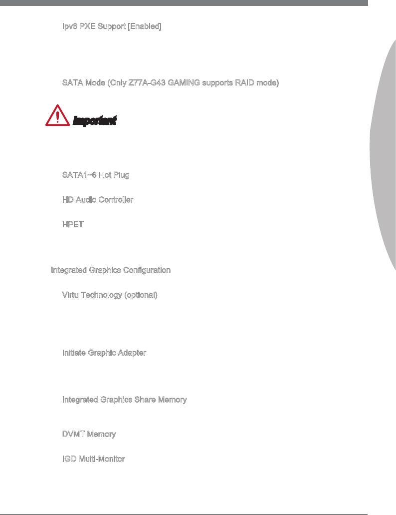
Ipv6 PXE Support [Enabled]
When “Enabled”, the system UEFI network stack wll be dened as IPv6 protocol.
Ths tem wll appear when “Network Stack” s enabled.
[Enabled] Enable the Ipv6 PXE boot support.
[Dsabled] Dsable the Ipv6 PXE boot support.
SATA Mode (Only Z77A-G43 GAMING supports RAID mode)
Ths tem s used to specfy RAID/ IDE/ AHCI mode for SATA port.
Important
You cannot swtch between AHCI and IDE f you already have your operatng system
nstalled. If you have nstalled your OS usng AHCI and you clear your BIOS/reset to
default settngs, you wll need to change ths functon back to AHCI to ensure proper
functonalty.
SATA1~6 Hot Plug
These tems are used to enable/ dsable the SATA ports hot plug support.
HD Audo Controller
Ths tem allows you to enable/ dsable the HD audo controller.
HPET
The HPET (Hgh Precson Event Tmers) s a component that s part of the chpset.
You can enable t, and wll provde you wth the means to get to t va the varous
ACPI methods.
Integrated Graphcs Conguraton
Press <Enter> to enter the sub-menu.
Vrtu Technology (optonal)
Enable or Dsable Vrtu GPU Swtchng Technology (f supported).
[-Mode] Provdes power savng features and specal processor
functonalty
[d-Mode] Uncompromsed 3D performance from the dscrete GPU
Intate Graphc Adapter
Choose whch adapter you wsh to make the prmary opton.
[IGD] Integrated Graphcs Dsplay
[PEG] PCI-Express Graphcs Devce
Integrated Graphcs Share Memory
The system shares memory to the onboard graphcs. Ths settng controls the exact
memory sze shared to the onboard graphcs.
DVMT Memory
Specfy the sze of DVMT memory to allocate for vdeo memory.
IGD Mult-Montor
Enables both ntegrated and dscrete graphcs at the same tme. When dsabled, t
wll default to Intated Graphcs Adapter selecton.
▶
▶
▶
▶
▶
▶
▶
▶
▶
▶
▶
2-8
BIOS Setup
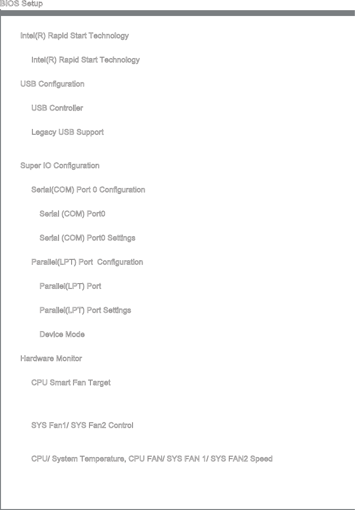
Intel(R) Rapd Start Technology
Press <Enter> to enter the sub-menu.
Intel(R) Rapd Start Technology
Ths tem s used to enable/ dsable the Intel Rapd Start technology.
USB Conguraton
Press <Enter> to enter the sub-menu.
USB Controller
Ths tem allows you to enable/ dsable the ntegrated USB 2.0 controller.
Legacy USB Support
Enable or dsable support for USB keyboards, mce and oppy drves. You wll be
able to use these devces wth operatng systems that do not support USB.
Super IO Conguraton
Press <Enter> to enter the sub-menu.
Seral(COM) Port 0 Conguraton
Press <Enter> to enter the sub-menu.
Seral (COM) Port0
Ths tem allows you to enable/ dsable the seral port.
Seral (COM) Port0 Settngs
Select an address and correspondng nterrupt for the seral port.
Parallel(LPT) Port Conguraton
Press <Enter> to enter the sub-menu.
Parallel(LPT) Port
Ths tem allows you to enable/ dsable the parallel port.
Parallel(LPT) Port Settngs
Select an address and correspondng nterrupt for the parallel port.
Devce Mode
Select a devce mode for the parallel port.
Hardware Montor
Press <Enter> to enter the sub-menu.
CPU Smart Fan Target
Controls CPU fan speed automatcally dependng on the current temperature and
to keep t wth a specc range. If the current CPU temperature reaches the target
value, the smart fan functon wll be actvated.
SYS Fan1/ SYS Fan2 Control
These tems allow users to select how percentage of speed for the SYSFAN1/
SYSFAN2.
CPU/ System Temperature, CPU FAN/ SYS FAN 1/ SYS FAN2 Speed
These tems show the current status of all of the montored hardware devces/
components such as CPU temperature/ system temperature and the few fans’
speeds.
▶
▶
▶
▶
▶
▶
▶
▶
▶
▶
▶
▶
▶
▶
▶
▶
▶
2-9
MS-7758
Chapter 2
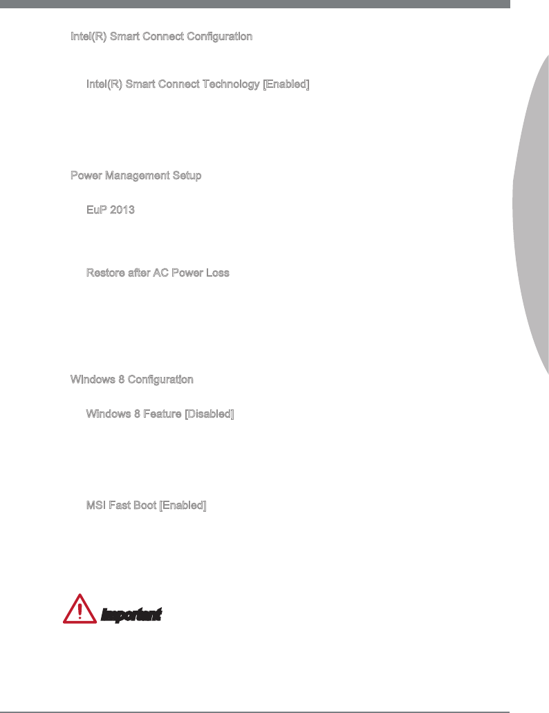
Intel(R) Smart Connect Conguraton
Set Intel Smart Connect Technology for optmzng system network performance n
sleep mode. Press <Enter> to enter the sub-menu.
Intel(R) Smart Connect Technology [Enabled]
Ths feature can update applcatons (ex. emal and socal networks) by perodcally
wakng your system from sleep mode. And you do not need to wat for the applcatons
to update when you wake up the system.
[Enabled] Enable Intel smart connect technology.
[Dsabled] Dsable Intel smart connect technology.
Power Management Setup
Press <Enter> to enter the sub-menu.
EuP 2013
Energy Usng Products Lot 6 2013 (EUP) reduces power consumpton when system
s o or n standby mode.
Note: When enabled, the system wll not support RTC wake up event functons.
Restore after AC Power Loss
Ths tem speces whether your system wll reboot after a power falure or nterrupt
occurs. Settngs are:
[Power O] Always leaves the computer n the power o state.
[Power On] Always leaves the computer n the power on state.
[Last State] Restore the system to the status before power falure or nterrupt
occurred.
Wndows 8 Conguraton
Press <Enter> to enter the sub-menu.
Wndows 8 Feature [Dsabled]
When enabled, the system wll swtch to the UEFI mode to meet the Wndows 8
requrement. Before enablng ths tem, please make sure all nstalled devces &
utltes (hardware & software) meet the Wndows 8 requrements.
[Enabled] Enable the Wndows 8 support.
[Dsabled] Dsable the Wndows 8 support.
MSI Fast Boot [Enabled]
MSI Fast Boot provdes the optmal settngs to accelerate the system bootng tme.
When enabled, the keyboard wll not be detected durng bootng.
[Enabled] Enable the MSI Fast Boot functon to mnmze bootng tme. And the
followng related "Fast Boot" tems wll be dsabled and xed.
[Dsabled] Allow you to enter BIOS setup wth hot key functon.
Important
If you want to enter BIOS n MSI Fast Boot mode, you have to clck the "GO2BIOS" tab
on Fast Boot utlty screen or press the "GO2BIOS" button (optonal) on the motherboard.
And then the system wll be restarted and go to BIOS mmedately.
▶
▶
▶
▶
▶
▶
▶
▶
2-10
BIOS Setup
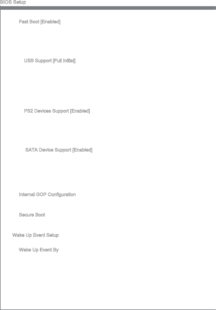
Fast Boot [Enabled]
Fast Boot s one of nnovaton n Wndows 8. When enabled, t allows user to dsable
the ntalzatons of USB, PS2 and SATA devces for acceleratng the system bootng
tme. Ths tem wll only be avalable when "MSI Fast Boot" s dsabled.
[Enabled] Enable the Fast Boot conguraton.
[Dsabled] Dsable the Fast Boot conguraton.
USB Support [Full Intal]
Ths tem s to determne whether to ntal the USB devce durng bootng.
When dsabled, all USB devces wll be un-avalable untl enterng OS and t wll
accelerate the system bootng tme.
[Dsabled] Dsable all ntalzatons of USB devces durng POST for faster
bootng tme.
[Full Intal] Enable all ntalzatons of USB devces durng POST. It wll extend
the bootng tme.
PS2 Devces Support [Enabled]
Ths tem s to determne whether to ntal the PS/2 devce durng bootng.
When dsabled, all PS/2 devces wll be un-avalable untl enterng OS and t wll
accelerate the system bootng tme.
[Dsabled] Dsable the PS2 devces durng POST for faster boot tme.
[Enabled] Enable the PS2 devces durng POST. It wll extend the boot tme.
SATA Devce Support [Enabled]
Ths tem s to determne whether to ntal the SATA devce durng bootng.
When dsabled, all SATA devces wll be un-avalable untl enterng OS and t wll
accelerate the system bootng tme.
[Dsabled] Dsable the SATA devces durng POST for faster boot tme.
[Enabled] Enable the SATA devces durng POST. It wll extend the boot
tme.
Internal GOP Conguraton
Press <Enter> to enter the sub-menu. Ths menu shows the GFX drver
nformaton.
Secure Boot
Press <Enter> to enter the sub-menu. Ths eld allows you to set the secure boot
settngs of Wndows to prevent the unauthorzed access.
Wake Up Event Setup
Press <Enter> to enter the sub-menu.
Wake Up Event By
Settng to [BIOS] actvates the followng elds, and use the followng elds to set the
wake up events. Settng to [OS], the wake up events wll be dened by OS.
▶
▶
▶
▶
▶
▶
▶
▶
2-11
MS-7758
Chapter 2
Resume By RTC Alarm
The eld s used to enable or dsable the feature of bootng up the system on a
scheduled tme/date.
Date/ HH:MM:SS
If Resume By RTC Alarm s set to [Enabled], the system wll automatcally resume
(boot up) on a specc date/hour/mnute/second speced n these elds (usng the
<+> and <-> to select the date & tme settngs).
Resume By PCI or PCI-E Devce
When set to [Enabled], the feature allows your system to be awakened from the
power savng modes through any event on PCI/ PCIe devce.
Resume From S3 by USB Devce
The tem allows the actvty of the USB devce to wake up the system from S3
(Suspend to RAM) sleep state.
Resume From S3/S4/S5 by PS/2 Mouse/ Keyboard
These tems determne whether the system wll be awakened from what power
savng modes when nput sgnal of the PS/2 mouse/ keyboard s detected.
Boot
Full Screen Logo Dsplay
[Enabled] The OS boots straght to the GUI wthout showng the POST screen,
[Dsabled] Shows the POST messages at boot.
Boot Mode Select [LEGACY+UEFI]
Ths tem determnes the system to boot from Legacy or UEFI BIOS mode.
[UEFI] Enable UEFI BIOS boot mode support only.
[LEGACY+UEFI] Enable both Legacy BIOS boot mode and UEFI BIOS boot
mode.
== Boot Opton Prortes==
1st~9th Boot
These tems are used to prortze the nstalled boot devces.
USB KEY Drve BBS Prortes/ UEFI Boot Drve BBS Prortes
1st~8th Boot
These tems are used to prortze the nstalled USB key drves/ UEFI boot drves.
▶
▶
▶
▶
▶
▶
▶
▶
▶
▶
2-12
BIOS Setup
Save & Ext
Dscard Changes and Ext
Ths t s used to abandon all changes and ext setup.
Save Changes and Reboot
Ths tem s used to save changes and reboot the system.
Save Changes
Ths tem s used to save changes.
Dscard Changes
Ths tem s used to abandon all changes.
Restore Defaults
Ths tem s used to load the optmzed default values set by the BIOS vendor.
== Boot Overrde ==
The nstalled storage devces wll appear on ths menu, you can select one of them be
a boot devce.
Bult-n EFI Shell
Use ths tem to enter the EFI Shell.
▶
▶
▶
▶
▶
▶
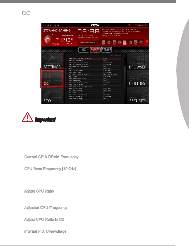
2-13
MS-7758
Chapter 2
OC
Important
Overclockng your PC manually s only recommended for advanced users.
Overclockng s not guaranteed, and f done mproperly, can vod your warranty or
severely damage your hardware.
If you are unfamlar wth overclockng, we advse you to use OC Gene for easy
overclockng.
Current CPU/ DRAM Frequency
These tems show the current clocks of CPU and Memory speed. Read-only.
CPU Base Frequency [10KHz]
Allows you to set the CPU Base clock (n 10KHz ncrements). You may overclock the
CPU by adjustng ths value. Please note that overclockng behavor and stablty s not
guaranteed.
Adjust CPU Rato
Controls the multpler that s used to determne nternal clock speed of the processor.
Ths feature can only be changed f the processor supports ths functon.
Adjusted CPU Frequency
It shows the adjusted CPU frequency. Read-only.
Adjust CPU Rato n OS
Enable ths tem to allow CPU rato changes n the OS by usng MSI Control Center II.
Internal PLL Overvoltage
Ths tem s used to adjust the PLL voltage.
•
•
•
▶
▶
▶
▶
▶
▶
2-14
BIOS Setup
EIST
Enhanced Intel SpeedStep technology allows you to set the performance level of the
mcroprocessor whether the computer s runnng on battery or AC power. Ths eld only
appears wth nstalled CPUs that support ths technology.
Intel Turbo Boost
Enables or dsables Intel Turbo Boost whch automatcally boosts CPU performance
above rated speccatons (when applcatons requests the hghest performance state
of the processor).
Enhanced Turbo [Dsabled]
[Enabled] All CPU cores would be ncreased to Intel maxmum turbo boost rato.
[Dsabled] Dsable ths functon.
OC Gene Functon Control
Ths tem allows you to enable/dsable the OC Gene functon.
My OC Gene [Default]
Ths tem s used to select whether OC Gene parameters are customzed by user.
[Default] OC Gene wll use default OC related parameters to overclock the
system.
[Customze] Allows user to congure the followng related "My OC Gene opton" sub-
menu manually for OC Gene.
DRAM Reference Clock [Auto]
Ths tem appears when a CPU that supports ths adjustment s nstalled. Ths tem
allows user to set the DRAM reference clock.
DRAM Frequency
Ths tem allows you to adjust the DRAM frequency. Please note the overclockng
behavor s not guaranteed.
Adjusted DRAM Frequency
It shows the adjusted DRAM frequency. Read-only.
DRAM Tmng Mode
Select whether DRAM tmng s controlled by the SPD (Seral Presence Detect)
EEPROM on the DRAM module. Settng to [Auto] enables DRAM tmngs and the
followng “Advanced DRAM Conguraton” sub-menu to be determned by BIOS based
on the conguratons on the SPD. Selectng [Lnk] or [Unlnk] allows users to congure
the DRAM tmngs for each channel and the followng related “Advanced DRAM
Conguraton” sub-menu manually.
Advanced DRAM Conguraton
Press <Enter> to enter the sub-menu. Ths sub-menu wll be actvated after settng [Lnk]
or [Unlnk] n “DRAM Tmng Mode”. User can set the memory tmng for each channel
of memory. The system may become unstable or unbootable after changng memory
tmng. If t occurs, please clear the CMOS data and restore the default settngs. (Refer
to the Clear CMOS jumper/ button secton to clear the CMOS data, and enter the BIOS
to load the default settngs.)
GT OverClockng
Ths tem allows you to enable/ dsable the overclockng of ntegrated graphcs.
▶
▶
▶
▶
▶
▶
▶
▶
▶
▶
▶
2-15
MS-7758
Chapter 2
GT Rato
Ths settng controls the rato of ntegrated graphcs frequency to enable the ntegrated
graphcs to run at derent frequency combnatons.
Adjusted GT Frequency
It shows the adjusted ntegrated graphcs frequency. Read-only.
Spread Spectrum
Ths functon reduces the EMI (Electromagnetc Interference) generated by modulatng
clock generator pulses.
Important
If you do not have any EMI problem, leave the settng at [Dsabled] for optmal system
stablty and performance. But f you are plagued by EMI, select the value of Spread
Spectrum for EMI reducton.
The greater the Spread Spectrum value s, the greater the EMI s reduced, and the
system wll become less stable. For the most sutable Spread Spectrum value, please
consult your local EMI regulaton.
Remember to dsable Spread Spectrum f you are overclockng because even a slght
jtter can ntroduce a temporary boost n clock speed whch may just cause your
overclocked processor to lock up.
CPU Core Voltage/ DRAM Voltage.
These tems are used to adjust the voltages.
Current CPU Core Voltage/ Current DRAM Voltage
These tems show current voltages. Read-only.
OC Retry Count [1]
Ths tem s used to set the number of bootng tmes wth the present over-clockng
settngs. If over-clockng has faled wth the desgnated bootng tmes, the system wll
restore the defaults at next boot.
Overclockng Proles
Press <Enter> to enter the sub-menu.
Overclockng Prole 1/ 2/ 3/ 4/ 5/ 6
Press <Enter> to enter the sub-menu.
Set Name for Overclockng Prole 1/ 2/ 3/ 4/ 5/ 6
Gve a name by typng n ths tem.
Save Overclockng Prole 1/ 2/ 3/ 4/ 5/ 6
Save the current overclockng settngs to ROM for selected prole.
Load/ Clear Overclockng Prole 1/ 2/ 3/ 4/ 5/ 6
Load/ Clear the stored prole settngs from ROM.
OC Prole Save to USB
Save the current overclockng settngs to USB ash dsk.
OC Prole Load from USB
Load the stored settngs from USB ash dsk.
▶
▶
▶
•
•
•
▶
▶
▶
▶
▶
▶
▶
▶
▶
▶
2-16
BIOS Setup
CPU Speccatons
Press <Enter> to enter the sub-menu. Ths sub-menu hghlghts all the key features of
your CPU. The nformaton wll vary by model and s read-only. You can also access ths
nformaton at any tme by pressng [F4]. Press <Enter> to enter the sub-menu.
CPU Technology Support
Press <Enter> to enter the sub-menu. The sub-menu shows the nstalled CPU
technologes. Read only.
MEMORY-Z
Press <Enter> to enter the sub-menu. Ths sub-menu hghlghts all the settngs and
tmngs of your DIMMs. Ths nformaton wll vary by model and s read-only. You can
also access ths nformaton at any tme by pressng [F5]. Press <Enter> to enter the
sub-menu.
DIMM1~4 Memory SPD
Press <Enter> to enter the sub-menu. The sub-menu dsplays the nformatons of
nstalled memory.
CPU Features
Press <Enter> to enter the sub-menu.
Hyper-Threadng Technology [Enabled]
The processor uses Hyper-Threadng technology to ncrease transacton
rates and reduces end-user response tmes. Intel Hyper-Threadng technology
treats the mult cores nsde the processor as mult logcal processors that can
execute nstructons smultaneously. In ths way, the system performance s hghly
mproved.
[Enable] Enable Intel Hyper-Threadng technology.
[Dsabled] Dsable ths tem f your operatng system does not support HT func-
ton.
Actve Processor Cores
Ths tem allows you to select the number of actve processor cores.
Lmt CPUID Maxmum
It s desgned to lmt the lsted speed of the processor to older operatng systems.
Execute Dsable Bt
Can prevent certan classes of malcous “buer overow” attacks where worms
can try to execute code to damage your system. It s recommended you keep ths
enabled always.
Intel Vrtualzaton Tech
Enhances vrtualzaton and allows the system to act as multple vrtual systems. See
Intel’s ocal webste for more nformaton.
Intel VT-D Tech
Ths tem s used to enable/dsable the Intel VT-D technology. For further nformaton
please refer to Intel’s ocal webste.
Hardware Prefetcher [Enabled]
Enable or dsable the hardware prefetcher of CPU.
[Enabled] Allows the CPU hardware prefetcher to automatcally pre-fetch data
▶
▶
▶
▶
▶
▶
▶
▶
▶
▶
▶
▶
2-17
MS-7758
Chapter 2
and nstructons from memory nto L2 cache for reducng the latency
tme assocated wth memory reads.
[Dsabled] Dsable the CPU hardware prefetcher.
Adjacent Cache Lne Prefetch [Enabled]
Enable or dsable the CPU hardware prefetcher to pre-fetch the adjacent cache
lne.
[Enabled] Allows the CPU hardware prefetcher to automatcally pre-fetch an
avalable cache lne for reducng the cache latency tme.
[Dsabled] CPU wll only fetch the requested cache lne.
Power Technology
Ths tem allows you to select the Intel Dynamc Power technology mode.
C1E Support
Enable system to reduce CPU power consumpton whle dle. Not all processors
support Enhanced Halt state (C1E).
OverSpeed Protecton
Montors current CPU draw as well as power consumpton; f t exceeds a certan
level, the processor automatcally reduces ts clock speed. For overclockng, t s
recommended ths feature s dsabled.
Intel C-State
C-state s a power management state that detects when the system s dle and
lowers power consumpton accordngly.
Package C State lmt
Ths eld allows you to select a C-state mode.
Long duraton power lmt (W)
Ths eld allows you to adjust the TDP power lmt for the long duraton.
Long duraton mantaned (s)
Ths eld allows you to adjust the mantanng tme for long duraton power lmt.
Short duraton power lmt (W)
Ths eld allows you to adjust the TDP power lmt for the short duraton.
Prmary/ Secondary Plane Current value (A)
These elds allow you to adjust over current value of CPU (prmary plane)/ GPU
(secondary plane) for turbo rato.
Prmary/ Secondary plane turbo power lmt (W)
These elds allow you to adjust the turbo power lmt of CPU (prmary plane)/ GPU
(secondary plane) for turbo boost.
1/2/3/4-Core Rato Lmt [Default]
These teme only appears when a CPU that support ths functon s nstalled. These
tems allow you to set the CPU ratos n derent actve cores n turbo boost mode.
▶
▶
▶
▶
▶
▶
▶
▶
▶
▶
▶
▶
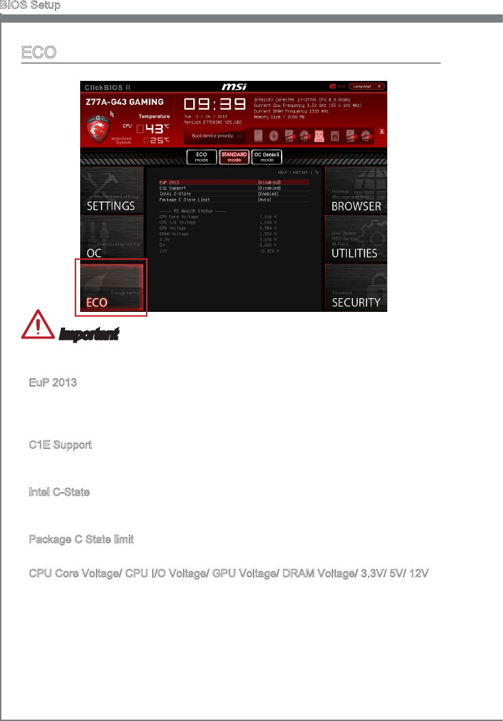
2-18
BIOS Setup
ECO
Important
Once you clck the “ECO” button n the pre-set area, some tems n ECO menu wll be
xed and un-adjustable.
EuP 2013
Energy Usng Products Lot 6 2013 (EUP) reduces power consumpton when system s
o or n standby mode.
Note: When enabled, the system wll not support RTC wake up event functons.
C1E Support
To enable ths tem to reduce the CPU power consumpton whle dle. Not all processors
support Enhanced Halt state (C1E).
Intel C-State
C-state s a power management state that detects when the system s dle and lowers
power consumpton accordngly.
Package C State lmt
Ths eld allows you to select a C-state mode.
CPU Core Voltage/ CPU I/O Voltage/ GPU Voltage/ DRAM Voltage/ 3.3V/ 5V/ 12V
These tems show the voltages. Read only.
.
▶
▶
▶
▶
▶
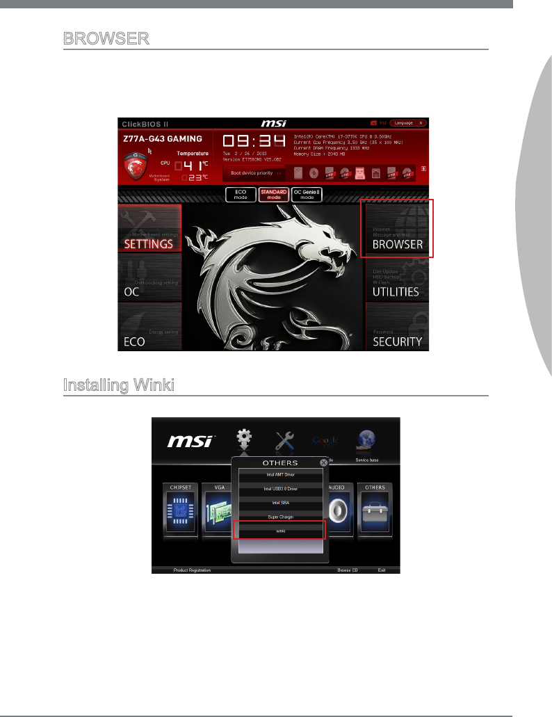
2-19
MS-7758
Chapter 2
BROWSER
Please nstall the MSI "Wnk" applcaton rst n the Wndows operatng system wth the
MSI Drver Dsc before usng the browser. Then you can clck the BROWSER to access
the Internet, e-mal and nstant messagng.
Installng Wnk
To nstall Wnk, follow the steps below:
Power on your computer and enter Wndows operatng system.
Insert MSI Drver Dsc nto the optcal drve. The setup screen wll automatcally
appear.
Clck Drver tab.
Clck OTHERS button.
Select Wnk to start nstallng.
When nshed, restart your computer.
1.
2.
3.
4.
5.
6.
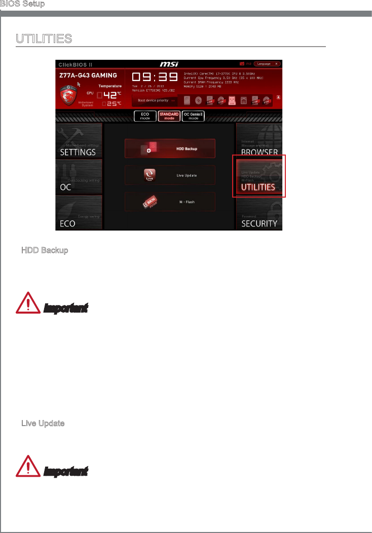
2-20
BIOS Setup
UTILITIES
HDD Backup
Hard dsk storage backups and restorng s one of the most common and mportant
tasks. Use ths utlty to create an mage of your HDD parttons and re-load them when
necessary.
Important
The HDD Backup can’t back up (/restore) mage to (/from) a partton where tself was
nstalled, so t’s strongly recommended to dvde HDD nto 2 parttons at least (1st for
OS; 2nd for data).
For HDD wth sngle partton only, the requrements for HDD Backup are:
An addtonal partton from another HDD (ex. USB HDD) for HDD Backup to back up
(/restore) mage to (/from) t.
Executng Wnk stored n USB ash drve/ MSI Drver Dsc by pressng <F11> to
choose boot devce durng POST.
Lve Update
Ths tool can detect and update your BIOS onlne so that you won’t need to spend tme
searchng manually.
Important
HDD Backup and Lve Update request Wnk, please nstall the "Wnk" software appl-
caton from MSI Drver Dsc n Wndows rst. And then you can access these two utltes
by clckng ther respectve buttons.
▶
1.
2.
▶
2-21
MS-7758
Chapter 2
M-Flash
BIOS Boot Functon
Ths allows you to enable/ dsable the system to boot from the BIOS le nsde USB
drve (FAT 32 format only).
Select one le to boot
When the BIOS Boot functon as sets to [Enabled], ths tem s selectable. Ths tem
allows to select partcular BIOS le from the USB/ Storage (FAT 32 format only)
drve. And the system wll boot from selected BIOS le.
Save BIOS to storage
Please setup a specc folder n specc USB/ Storage drve to save BIOS le from
BIOS ROM chp data. Note: t only supports FAT 32 le system drve.
Update BIOS
Press <Enter> to enter the sub-menu.
Select one le to update BIOS
Selects a BIOS le n the USB ash dsk drve to update the BIOS. The system
wll reboot after updatng. The USB ah dsk drve should be n NTFS / FAT 32
format
Select one le to update BIOS and ME
Selects a BIOS le n the USB ash dsk drve to update the BIOS and ME. The
system wll reboot after updatng. The USB ah dsk drve should be n NTFS /
FAT 32 format
▶
▶
▶
▶
▶
▶
▶
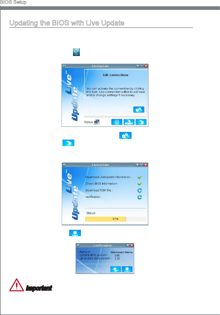
2-22
BIOS Setup
Updatng the BIOS wth Lve Update
Ths secton tells you how to update the BIOS by usng the Lve Update utlty before
enterng Operatng System. Lve Update wll update the BIOS automatcally when
connectng to the Internet. To update the BIOS wth the Lve Update utlty:
Clck Lve Update button on the BIOS UTILITIES menu. (The Wnk must be
nstalled).
1.
Setup the connecton by clck the settng button f necessary.
Clck the next button .
Lve Update wll automatcally detect the verson of BIOS and download the ap-
proprate le.
2.
3.
4.
Clck the conrm button to update the BIOS.5.
Important
Do not unplug or shut o your system durng BIOS Flash. Incorrect BIOS ashng can
cause the motherboard to not POST. Please ensure you have the correct verson and
model of your motherboard BIOS when updatng.
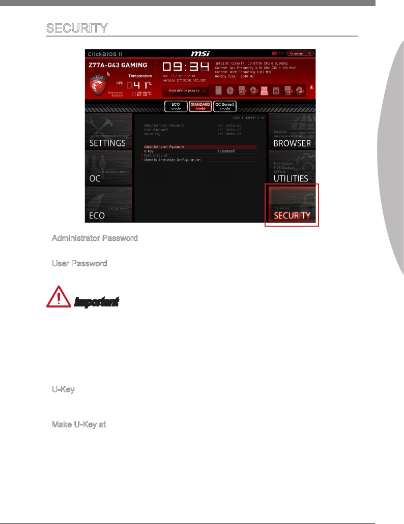
2-23
MS-7758
Chapter 2
SECURITY
Admnstrator Password
Set the admnstratve password that wll be requred to enter the BIOS.
User Password
Set the user password that wll be requred to enter the operatng system.
Important
When selectng the Admnstratve / User Password tems, a password box wll appear
on the screen. Type the password then press <Enter>. The password typed now wll re-
place any prevous set password from CMOS memory. You wll be prompted to conrm
the password. You may also press <Esc> to abort the selecton.
To clear a set password, press <Enter> when you are prompted to enter a new pass-
word. A message wll conrm the password s beng dsabled. Once the password s
dsabled, you can enter the setup and OS wthout authorzaton.
U-Key
Enable or dsable USB drver devce as key. Ths requres the USB devce to be plugged
n for access to the computer..
Make U-Key at
When the “U-Key” as sets to [Enabled], ths tem s selectable. Ths tem allows you to
specfy the USB drve.
▶
▶
▶
▶

2-24
BIOS Setup
Chasss Intruson Conguraton
Press <Enter> to enter the sub-menu.
Chasss Intruson
Enables or dsables the feature of recordng the chasss ntruson status and ssung
a warnng message f opened. To clear the warnng logs, set the eld to [Reset]. The
settng of the eld wll return to [Enabled] later.
▶
▶

The Realtek audo provdes 10-channel DAC that smul-
taneously supports 7.1 sound playback and 2 channels
of ndependent stereo sound output (multple streamng)
through the Front-Out-Left and Front-Out-Rght chan-
nels.
Appendx A
Realtek Audo
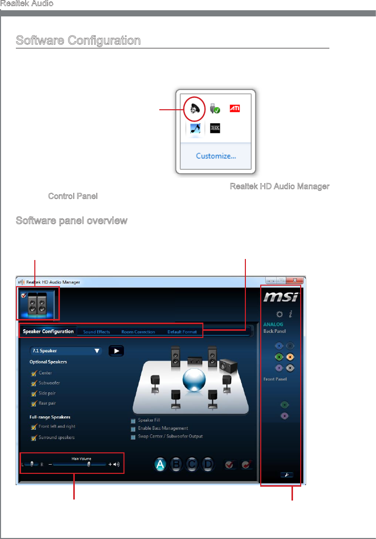
A-2
Realtek Audo
Software Conguraton
After nstallng the audo drver (see Chapter 1 - Drver and Utltes), the “Realtek HD
Audo Manager” con wll appear at the notcaton area (lower rght of the screen). You
may double clck the con and the GUI wll pop up accordngly.
double clck the con
It s also avalable to enable the audo drver by clckng the Realtek HD Audo Manager
from the Control Panel.
Software panel overvew
The followng gure descrbes the functon of the Realtek HD Audo Manager panel.
Devce Selecton
Volume Adjustment
Applcaton Enhancement
Jack status panel
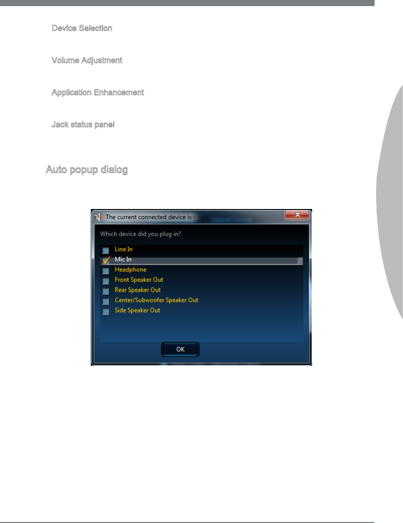
A-3
MS-7758
Appendx A
Devce Selecton
Here you can select a audo output source to change the related optons. The “check”
sgn (n orange) ndcates the devces as default.
Volume Adjustment
You can control the volume or balance the rght/left sde of the speakers that you
plugged n front or rear panel by adjust the bar.
Applcaton Enhancement
The array of optons wll provde you a complete gudance of antcpated sound eect for
both output and nput devce.
Jack status panel
Ths panel depcts all render and capture devces currently connected wth your com-
puter.
Auto popup dalog
When you plug nto the devce at the jack, a dalogue wndow wll pop up askng you
whch devce s current connected.
As you know, each jack corresponds to ts default settng, you can refer to the next sec-
ton “Hardware Default Settng”.
■
■
■
■
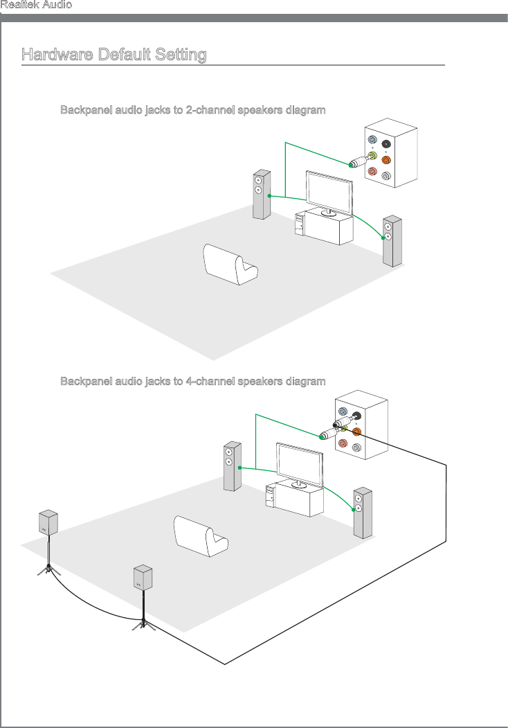
A-4
Realtek Audo
Hardware Default Settng
The followng dagrams are audo back panel default settng.
Backpanel audo jacks to 2-channel speakers dagram
Front
Backpanel audo jacks to 4-channel speakers dagram
Rear
Front
■
■
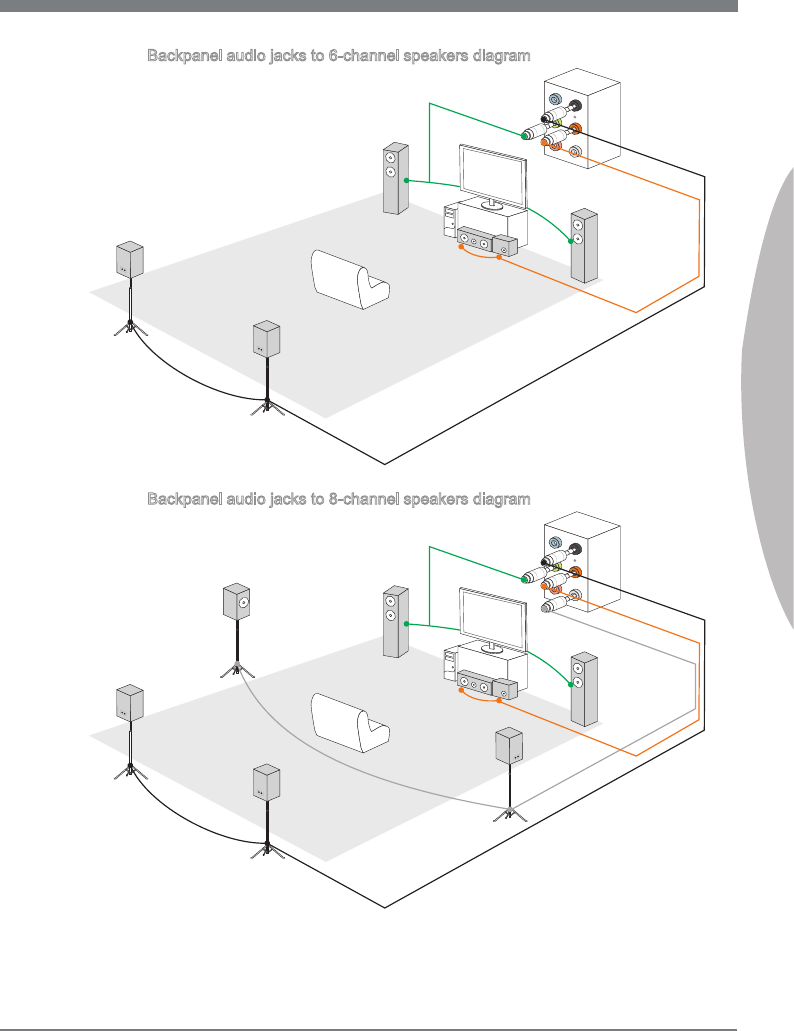
A-5
MS-7758
Appendx A
Backpanel audo jacks to 6-channel speakers dagram
Rear
Front
Center&Subwoofer
Backpanel audo jacks to 8-channel speakers dagram
Rear
Front
Center&Subwoofer
Side Surround
■
■


Ths appendx wll assst users n congurng and en-
ablng RAID functonalty and acceleratng system on
platforms
Appendx B
Intel RAID

B-2
Intel RAID
Introducton
The manboard comes wth the Intel RAID controller that allows you to congure SATA
hard drves as RAID sets.
SATA hard drves delver blsterng transfer speeds up to 6 Gb/s. Seral ATA uses long,
thn cables, makng t easer to connect your drve and mprovng the arow nsde your
PC. The most outstandng features are:
Supports 3 Gb/s or 6 Gb/s transfers wth CRC error checkng.
Supports Hot-plug-n-play feature.
Data handlng optmzatons ncludng tagged command queung, elevator seek and
packet chan command.
Intel® RAID controller oers RAID level 0 (Strpng), RAID level 1 (Mrrorng and Duplex-
ng), RAID level 5 (Block Interleaved Dstrbuted Party), RAID level 10 (A Strpe of Mr-
rors) , Intel® Rapd Storage Technology.
RAID 0 breaks the data nto blocks whch are wrtten to separate hard drves. Spread-
ng the hard drve I/O load across ndependent channels greatly mproves I/O perfor-
mance.
RAID 1 provdes data redundancy by mrrorng data between the hard drves and pro-
vdes enhanced read performance.
RAID 5 Provdes data strpng at the byte level and also strpe error correcton nforma-
ton. Ths results n excellent performance and good fault tolerance. Level 5 s one of the
most popular mplementatons of RAID.
RAID 10 Not one of the orgnal RAID levels, multple RAID 1 mrrors are created, and a
RAID 0 strpe s created over these.
Intel® Rapd Storage Technology s the advanced ablty for two RAID volumes to share
the combned space of two hard drves beng used n unson.
Intel® Rapd Storage Technology utlzes RAID 1 functonalty to copy data from a des-
gnated Master drve to a desgnated Recovery drve. The sze of the Master drve must
be less than or equal to the sze of the Recovery drve. When a Recovery volume s
created, complete capacty of the Master drve wll be used as the Master volume. Only
one Recovery Volume can exst on a system. There are 2 methods of updatng the
data on the Master to the Recovery drve. They are Contnuous Update Polcy and On
Request Update Polcy.
Important
The least number of hard drves for RAID 0, RAID 1, Recovery or Matrx mode s 2. The
least number of hard drves for RAID 10 mode s 4. And the least number of hard drves
for RAID 5 mode s 3.
All the nformaton/ volumes/ pctures lsted n your system mght der from the llustra-
tons n ths appendx.
1.
2.
3.
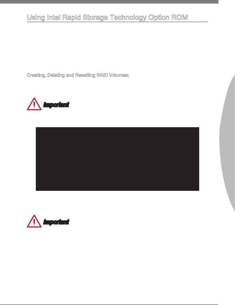
B-3
MS-7758
Appendx B
Usng Intel Rapd Storage Technology Opton ROM
The Intel Rapd Storage Technology Opton ROM should be ntegrated wth the sys-
tem BIOS on all manboards wth a supported Intel chpset. The Intel Rapd Storage
Technology Opton ROM s the Intel RAID mplementaton and provdes BIOS and DOS
dsk servces. Please use <Ctrl> + <I> keys to enter the “Intel® RAID for Seral ATA”
status screen, whch should appear early n system boot-up, durng the POST (Power-
On Self Test). Also, you need to enable the RAID functon n BIOS to create, delete and
reset RAID volumes.
Creatng, Deletng and Resettng RAID Volumes:
The Seral ATA RAID volume may be congured usng the RAID Conguraton utlty
stored wthn the Intel RAID Opton ROM. Durng the Power-On Self Test (POST), the
followng message wll appear for a few seconds.
Important
The “Devce Model”, “Seral #” and “Sze” n the followng example mght be derent
from your system.
RAID Volumes
None dened.
Physcal Dsks:
Port Devce Model Seral # Sze Type/Status(Vol ID)
1 XXXXXXXXXXXXX XXXXXXXXXXXXX XXX.XGB Non-RAID Dsk
2 XXXXXXXXXXXXX XXXXXXXXXXXXX XXX.XGB Non-RAID Dsk
Press <CTRL-I> to enter Conguraton Utlty..
After the above message shows, press <Ctrl> and <I> keys smultaneously to enter the
Intel Rapd Storage Technology Opton ROM.
Important
The followng procedure s only avalable wth a newly-bult system or f you are renstall-
ng your OS. It should not be used to mgrate an exstng system to RAID.
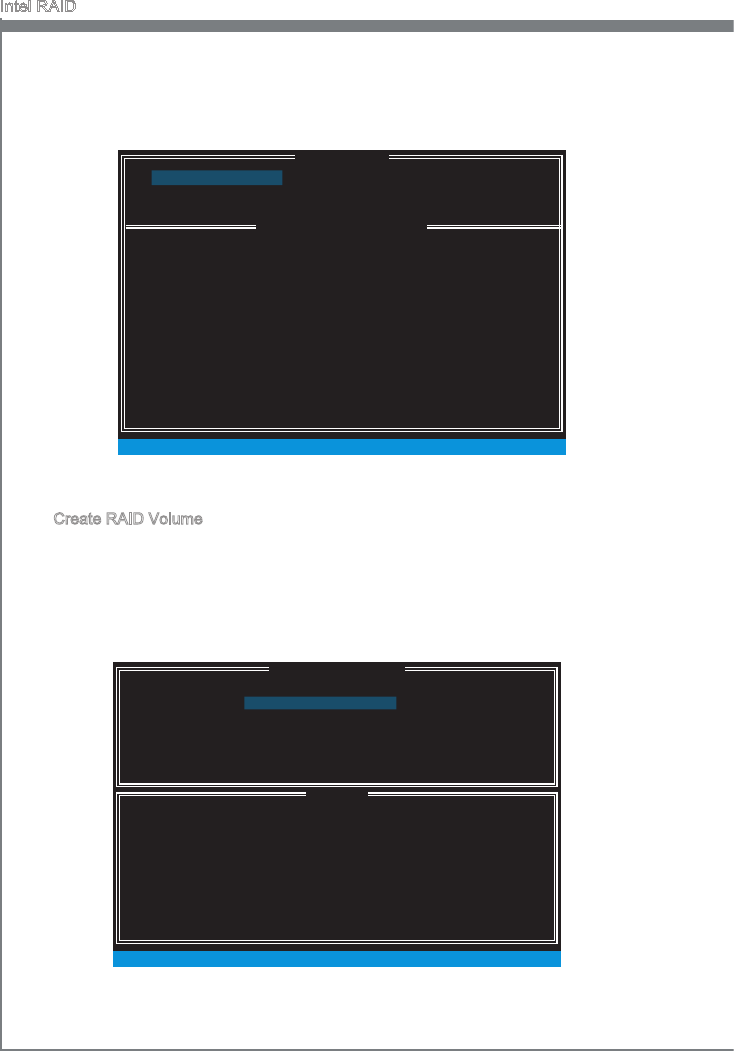
B-4
Intel RAID
After pressng the <Ctrl> and <I> keys smultaneously, the followng wndow wll ap-
pear:
Create RAID Volume
Select opton 1 “Create RAID Volume” and press <Enter> key. The followng screen
appears. Then n the Name eld, specfy a RAID Volume name and then press the
<TAB> or <Enter> key to go to the next eld.
Use the arrow keys to select the RAID level best suted to your usage model n
RAID Level.
■
1.
2.
[ ]
CREATE VOLUME MENU
[ ]
HELP
Name :
RAID 1 : Mrrors data (redundancy) .
[ ↑↓] - Change [TAB] - Next [ESC] - Prevous Menu [ENTER] - Select
RAID Level :
Dsks :
Strp Sze :
Capacty :
Sync :
Volume0
RAID1(Mrror)
Select Dsks
N / A
XXX.X GB
N / A
Create Volume
MAIN MENU
[ ]
DISK / VOLUME INFORMATION
[ ]
4. Recovery Volume Optons
5. Acceleraton Optons
6. Ext
RAID Volumes :
None dened.
Physcal Devces :
Port Devce Model Seral # Sze Type/Status (Vol ID)
1 XXXX-XXXXXXXX XXXXXXXXXXXXXX XXX.XGB Non-RAID Dsk
2 XXXX-XXXXXXXX XXXXXXXXXXXXXX XXX.XGB Non-RAID Dsk
[ ↑↓] - Select [ESC] - Ext [ENTER] - Select Menu
1. Create RAID Volume
2. Delete RAID Volume
3. Reset Dsks to Non-RAID
[ ]
MAIN MENU
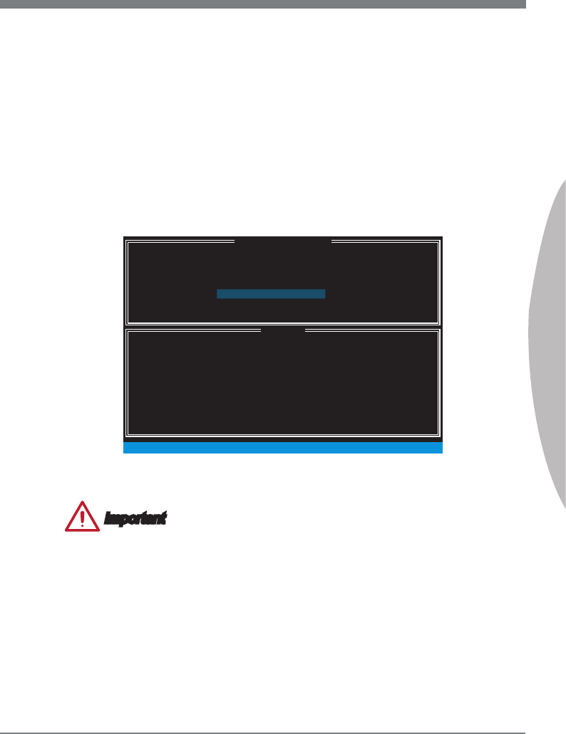
B-5
MS-7758
Appendx B
In the Dsk eld, press <Enter> key and use <Space> key to select the dsks you
want to create for the RAID volume, then clck <Enter> key to nsh selecton. Ths
eld wll become avalable accordng to the selected RAID level.
Then select the strp sze for the RAID array by usng the “upper arrow”
or “down arrow” keys to scroll through the avalable values, and pressng
the <Enter> key to select and advance to the next eld. The avalable val-
ues range from 4KB to 128 KB n power of 2 ncrements. The strp sze should
be chosen based on the planned drve usage. Here are some typcal values:
RAID0 -128KB / RAID10 - 64KB / RAID5 - 64KB. Ths eld wll become avalable
accordng to the selected RAID level.
Then select the capacty of the volume n the Capacty eld. The default value s the
maxmum volume capacty of the selected dsks.
3.
4.
5.
[ ]
CREATE VOLUME MENU
[ ]
HELP
Name :
The default value ndcates the maxmum capacty usng the selected
dsks. Enterng a lower capacty allows you to create a second
volume on these dsks.
[ ↑↓] - Change [TAB] - Next [ESC] - Prevous Menu [ENTER] - Select
RAID Level :
Dsks :
Strp Sze :
Capacty :
Sync :
Volume0
RAID1(Mrror)
Select Dsks
N / A
XXX.X GB
N / A
Create Volume
Important
Snce you want to create two volumes, ths default sze (maxmum) needs to be re-
duced. Type n a new sze for the rst volume. As an example: f you want the rst
volume to span the rst half of the two dsks, re-type the sze to be half of what s shown
by default. The second volume, when created, wll automatcally span the remander of
two hard drves.
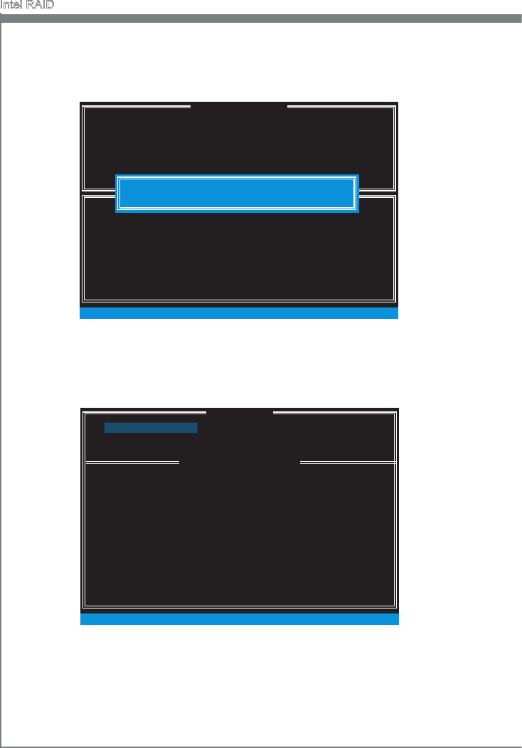
B-6
Intel RAID
Then the followng screen appears to ndcate that the creaton s nshed.7.
Go to the Create Volume eld and press <Enter>, the followng screen appears for
you to conrm f you are sure to create the RAID volume. Press <Y> to contnue.
6.
[ ]
CREATE VOLUME MENU
[ ]
HELP
Name :
Press ENTER to create the speced volume.
[ ↑↓] - Change [TAB] - Next [ESC] - Prevous Menu [ENTER] - Select
RAID Level :
Dsks :
Strp Sze :
Capacty :
Sync :
Volume0
RAID1(Mrror)
Select Dsks
N / A
XXX.X GB
N / A
Create Volume
WARNING : ALL DATA ON SELECTED DISKS WILL BE LOST.
Are you sure you want to create ths volume? (Y / N) :
DISK / VOLUME INFORMATION
[ ]
4. Recovery Volume Optons
5. Acceleraton Optons
6. Ext
RAID Volumes :
ID Name Level Strp Sze Status Bootable
0 Volume0 RAID1(Mrror) N / A XXX.XGB Normal Yes
Physcal Devces :
Port Devce Model Seral # Sze Type/Status (Vol ID)
1 XXXX-XXXXXXXX XXXXXXXXXXXXXX XXX.XGB Member Dsk(0)
2 XXXX-XXXXXXXX XXXXXXXXXXXXXX XXX.XGB Member Dsk(0)
[ ↑↓] - Select [ESC] - Ext [ENTER] - Select Menu
1. Create RAID Volume
2. Delete RAID Volume
3. Reset Dsks to Non-RAID
MAIN MENU
[ ]
[ ]
MAIN MENU
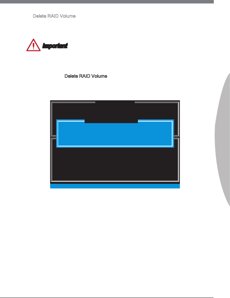
B-7
MS-7758
Appendx B
Delete RAID Volume
Here you can delete the RAID volume, but please be noted that all data on RAID
drves wll be lost.
Important
If your system currently boots to RAID and you delete the RAID volume n the Intel RAID
Opton ROM, your system wll become un-bootable.
Select opton 2 Delete RAID Volume from the man menu screen and press <Enter>
key to select a RAID volume for deleton. Then press <Delete> key to delete the
selected RAID volume. The followng screen appears.
[ ]
DELETE VOLUME MENU
[ ]
HELP
Deletng a volume wll reset the dsks to non-RAID.
[ ↑↓] - Select [ESC] - Prevous Menu [DEL] - Delete Volume
WARNING : ALL DISK DATA WILL BE DELETED.
(Ths does not apply to Recovery volumes)
Name Level Drves Capacty Status Bootable
Volume0 RAID1(Mrror) 2 XXX.XGB Normal Yes
ALL DATA IN THE VOLUME WILL BE LOST!
(Ths does not apply to Recovery volumes)
Are you sure you want to delete “Volume0”? (Y / N) :
DELETE VOLUME VERIFICATION
[ ]
Press <Y> key to accept the volume deleton.
■
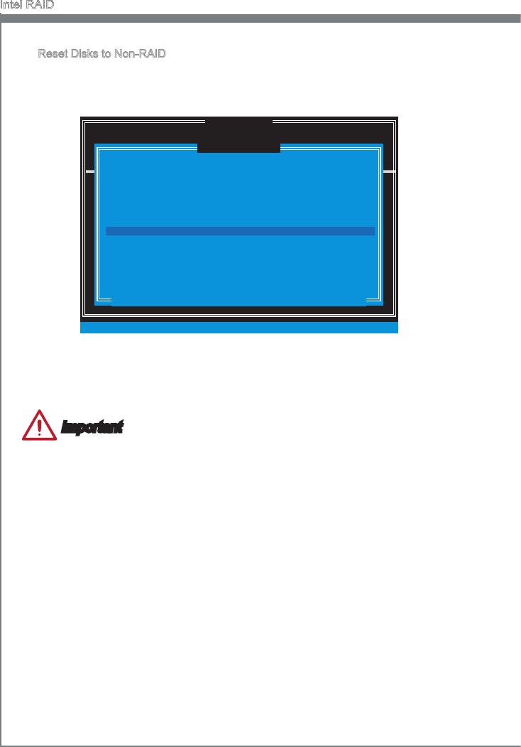
B-8
Intel RAID
Reset Dsks to Non-RAID
Select opton 3 Reset Dsks to Non-RAID and press <Enter> to delete the RAID
volume and remove any RAID structures from the drves. The followng screen
appears:
DISK / VOLUME INFORMATION
[ ]
4. Recovery Volume Optons
4. Recovery Volume Optons
5. Ext
RAID Volumes :
None dened.
Physcal Devces :
Port Devce Model Seral # Sze Type/Status (Vol ID)
1 XXXX-XXXXXXXX XXXXXXXXXXXXXX XXX.XGB Non-RAID Dsk
2 XXXX-XXXXXXXX XXXXXXXXXXXXXX XXX.XGB Non-RAID Dsk
[ ↑↓] - Select [ESC] - Ext [ENTER] - Select Menu
1. Create RAID Volume
2. Delete RAID Volume
Resettng RAID dsk wll remove ts RAID structures
and revert t to a non-RAID dsk.
[ ]
RESET RAID DATA
WARNING : Resettng a dsk causes all data on the dsk to be lost.
(Ths does not apply to Recovery volumes)
Select the dsks that should be reset.
[ ↑↓] - Prevous/ Next [SPACE] - Selects [ENTER] - Selecton Complete
Port Drve Model Seral # Sze Status
1 XXXX-XXXXXXXX XXXXXXXXXXXXXX XXX.XGB Member Dsk
2 XXXX-XXXXXXXX XXXXXXXXXXXXXX XXX.XGB Member Dsk
[ ]
MAIN MENU
Use the <Space> key to select the dsks and press <Enter> key. A conrmaton sen-
tence wll appear below, and then press <Y> key to accept the selecton.
Important
You wll lose all data on the RAID drves and any nternal RAID structures when you
perform ths operaton.
Possble reasons to “Reset Dsks to Non-RAID” could nclude ssues such as ncom-
patble RAID conguratons or a faled volume or faled dsk.
■
•
•
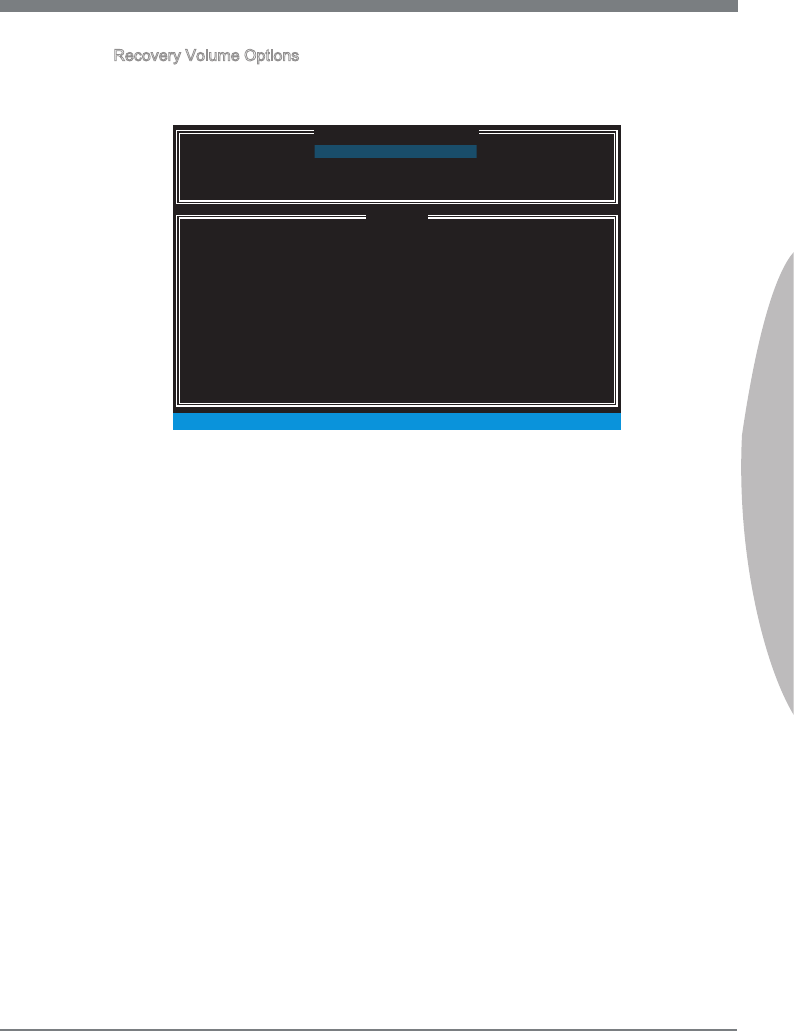
B-9
MS-7758
Appendx B
Recovery Volume Optons
Select opton 4 Recovery Volume Optons and press <Enter> to change recovery
volume mode. The followng screen appears:
[ ]
RECOVERY VOLUME OPTIONS
[ ]
HELP
Enable Only Recovery Dsk - enables recovery dsk f avalable and
dsables master dsk.
Enable Only Master Dsk - enables master dsk f avalable and
dsables recovery dsk.
Actons wll result n change from Contnuous Update mode to On-Request.
[ ↑↓] - select [ESC] - Prevous Menu [ENTER] - Select
1. Enable Only Recovery Dsk
2. Enable Only Master Dsk
Recovery mode wll change from Contnuous Update to On-Request after you en-
able “Only Recovery Dsk” or “Only Master Dsk”.
■
B-10
Intel RAID
Important
Please follow the nstructon below to make an “Intel
®
RAID Drver” for yourself.
Insert the MSI DVD nto the DVD-ROM drve.
Clck the “Browse CD” on the Setup screen.
Copy all the contents n \\Storage\Intel\PCH 7\f6py-x86 or f6py-x64 to a formatted
oppy dskette.
The drver dskette for Intel
®
RAID Controller s done.
•
•
•
•
Installng Drver
New Wndows 7/ Wndows XP Installaton
The followng detals the nstallaton of the drvers whle nstallng operatng system.
When you start nstallng Wndows XP, you may encounter a message statng,
“Setup could not determne the type of one or more mass storage devces nstalled
n your system”. If ths s the case, then you are already n the rght place and are
ready to supply the drver. If ths s not the case, then press F6 when prompted at
the begnnng of Wndows setup.
Press the “S” key to select “Specfy Addtonal Devce”.
You should be prompted to nsert a oppy dsk contanng the Intel
®
RAID drver
nto the A: drve.
Note: For Wndows XP, you can use the USB oppy drve only.
For Wndows 7 you can use CD/ DVD/ USB drve.
■
1.
2.
3.
For Wndows 7: Durng the Operatng system nstallaton, after selectng the loca-
ton to nstall Wndows 7 clck on “Load Drver” button to nstall a thrd party SCSI or
RAID drver.
When prompted, nsert the oppy dsk or meda (CD/DVD or USB) you created n
step 3 and press Enter.
You should be shown a lst of avalable SCSI Adapters.
Select the approprate Intel RAID controller and press ENTER.
The next screen should conrm that you have selected the Intel
®
RAID controller.
Press ENTER agan to contnue.
You have successfully nstalled the Intel
®
Rapd Storage Technology drver, and
Wndows setup should contnue.
Leave the dsk n the oppy drve untl the system reboots tself. Wndows setup wll
need to copy the les from the oppy agan after the RAID volume s formatted, and
Wndows setup starts copyng les.
4.
5.
6.
7.
8.
9.
10.
B-11
MS-7758
Appendx B
Exstng Wndows Drver Installaton
Insert the MSI DVD nto the DVD-ROM drve.
The DVD wll auto-run and the setup screen wll appear.
Under the Drver tab, clck on Intel RAID Drvers.
The drvers wll be automatcally nstalled.
Conrmng Wndows Drver Installaton
From Wndows, open the Control Panel from My Computer followed by the System
con.
Choose the Hardware tab, then clck the Devce Manager tab.
Clck the “+” n front of the SCSI and RAID Controllers hardware type. The drver
Intel(R) SATA RAID Controller should appear.
■
1.
2.
3.
4.
■
1.
2.
3.
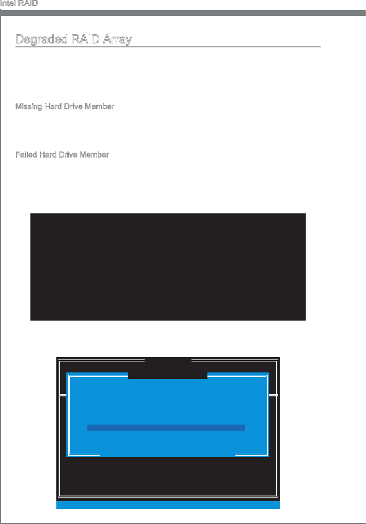
B-12
Intel RAID
Degraded RAID Array
A RAID 1, RAID 5 or RAID 10 volume s reported as degraded when one of ts hard drve
members fals or s temporarly dsconnected, and data mrrorng s lost. As a result, the
system can only utlze the remanng functonal hard drve member. To re-establsh
data mrrorng and restore data redundancy, refer to the procedure below that corre-
sponds to the current stuaton.
Mssng Hard Drve Member
Make sure the system s powered o.
Reconnect the hard drve.
Reboot the system to Wndows; the rebuld wll occur automatcally.
Faled Hard Drve Member
Make sure the system s powered o.
Replace the faled hard drve wth a new one that s of equal or greater capacty.
Reboot the system to Intel RAID Opton ROM by press <Ctrl> and <I> keys smul-
taneously durng the Power-On Self Test (POST).
1.
2.
3.
1.
2.
3.
Select the port of the destnaton dsk for rebuldng, and then press ENTER.
4.
RAID Volumes
ID Name Level Strp Sze Status Bootable
0 Volume0 RAID 1(Mrror) N/A XXX.XGB Degraded Yes
Physcal Dsks:
Port Devce Model Seral # Sze Type/Status(Vol ID)
1 XXXXXXXXXXXXX XXXXXXXXXXXXX XXX.XGB Member Dsk (0)
2 XXXXXXXXXXXXX XXXXXXXXXXXXX XXX.XGB Member Dsk (0)
Press <CTRL-I> to enter Conguraton Utlty..
DISK / VOLUME INFORMATION
[ ]
4. Recovery Volume Optons
4. Recovery Volume Optons
5. Ext
RAID Volumes :
None dened.
Physcal Devces :
Port Devce Model Seral # Sze Type/Status (Vol ID)
1 XXXX-XXXXXXXX XXXXXXXXXXXXXX XXX.XGB Non-RAID Dsk
2 XXXX-XXXXXXXX XXXXXXXXXXXXXX XXX.XGB Non-RAID Dsk
[ ↑↓] - Select [ESC] - Ext [ENTER] - Select Menu
1. Create RAID Volume
2. Delete RAID Volume
“Degraded” volume and dsk avalable for rebuldng detected. Selectng
a dsk ntates a rebuld. Rebuld completes n the operatng system.
[ ]
DEGRADED VOLUME DETECTED
Select the port of the destnaton dsk for rebuldng (ESC to ext):
[ ↑↓] - Prevous/ Next [ENTER] - Select [ESC] - Ext
Port Drve Model Seral # Sze
1 XXXX-XXXXXXXX XXXXXXXXXXXXXX XXX.XGB
[ ]
MAIN MENU
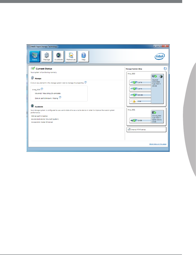
B-13
MS-7758
Appendx B
Ext Intel RAID Opton ROM, and then reboot to Wndows system.
When prompted to rebuld the RAID volume, clck ‘Yes’.
The Intel Rapd Storage Technology applcaton wll be launched. Rght-clck the new
hard drve and select ‘Rebuld to ths Dsk’. The ‘Rebuld Wzard’ wll be launched
whch wll gude you through the process of rebuldng to the new hard drve.
5.
6.
7.
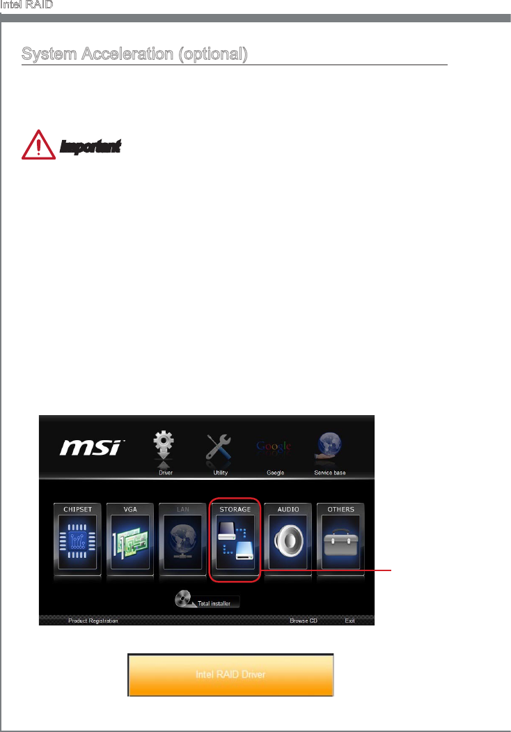
B-14
Intel RAID
System Acceleraton (optonal)
Intel® Rapd Storage Technology use a SSD as a cache. Whch can store frequently
used data wthout havng to use a slow vrtual dsk or depend on RAM. The SSD cache
wth the advantages of hgh-speed read/wrte and non-volatle memory to accelerate the
system performance.
Important
Check your SSD manufacturer's webste, upgrade rmware n order to support
Intel®
Rapd Storage Technology
.
Intel® Rapd Storage Technology can only work wth RAID mode. Even though there s
only one hard drve, you must set the SATA Mode to RAID n BIOS. The OS must be
nstalled n the RAID ready dsk n order to use the SSD cachng.
Follow these steps to enable system acceleraton. If Wndows has been nstalled n
RAID mode, skp to the step 5.
Reboot and enter the BIOS steup.
Set the SATA Mode to RAID n BIOS.
Install Intel
®
RAID controller drver. Please refer to the secton "Installng Drver".
Install Wndows operatng system.
Powered o.
Connect the SSD.
Reboot the system to Wndows.
Insert the MSI DVD nto the DVD-ROM drve.
1.
2.
3.
4.
5.
6.
7.
8.
Clck the “STORAGE” on the Setup screen.
9.
Clck the "Intel RAID Drver" to nstall Intel® Rapd Storage Technology applcaton.10.
Clck here
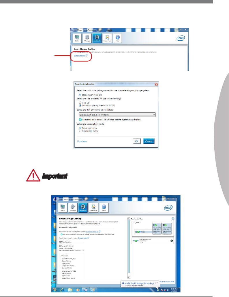
B-15
MS-7758
Appendx B
Run Intel® Rapd Storage Technology applcaton.
Clck "Enable acceleraton" under Accelerate.
11.
12.
Clck here
Select the acceleraton optons.13.
Clck OK and reboot the system.
The page refreshes and reports the new acceleraton conguraton n the Acceleraton
Vew.
Important
You can clck “More help on ths page” or "More help" of the Intel
®
Rapd Storage
Technology applcaton to vew more nformaton.
14.
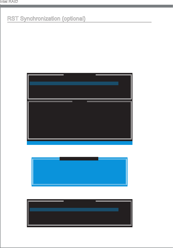
B-16
Intel RAID
RST Synchronzaton (optonal)
If you are usng Maxmzed mode as the Acceleraton mode, the data on the hard dsk
s not always synchronzed wth the data n the SSD cache. In some stuatons, you may
want to manually sync the dsks for avodng data loss.
Follow these steps to sync manually.
Reboot system, durng the Power-On Self Test (POST) press, press <Ctrl> and <I>
keys smultaneously to enter the Intel Rapd Storage Technology Opton ROM.
Select opton 5 “Acceleraton Optons” and press <Enter> key. The followng screen
appears.
1.
2.
[ ]
ACCELERATION OPTIONS
[ ]
HELP
Name
Press 's' to synchronze data from the cache devce to
the Accelerated Dsk/Volume.
Press 'r' to remove the Dsk/Volume Acceleraton.
WARNING: IT IS RECOMMENDED THAT YOU [ERFORM A SYNCHRONIZATION
BEFORE REMOVING ACCELERATION.
[ ↑↓] - Select [ESC] - Prevous Menu
Type Capacty Status
DISK PORT 0 Non-RAID Dsk 153.4GB
Mode
Maxmzed No Sync
Press <S> to synchronze data.3.
[ ]
ACCELERATION OPTIONS
Name Type Capacty Status
DISK PORT 0 Non-RAID Dsk 153.4GB
Mode
Maxmzed In Sync
DISK / VOLUME INFORMATION
[ ]
5. Ext
SYNCHRONIZING THE DATA MAY TAKE SEVERAL MINUTES.
DO NOT INTERRUPT THE PROCESS!
[ ]
SYNCHRONIZATION VERIFICATION
Are you sure you want to synchronze data to
"DISK PORT 0"? (Y/N):
When prompted, press <Y> to conrm.4.
Once synchronzaton s complete, the status wll change to In Sync.
5.

Ths chapter descrbes how to nstall Wndows XP wth
IDE or AHCI mode.
Appendx C
Install Wndows XP
Notes
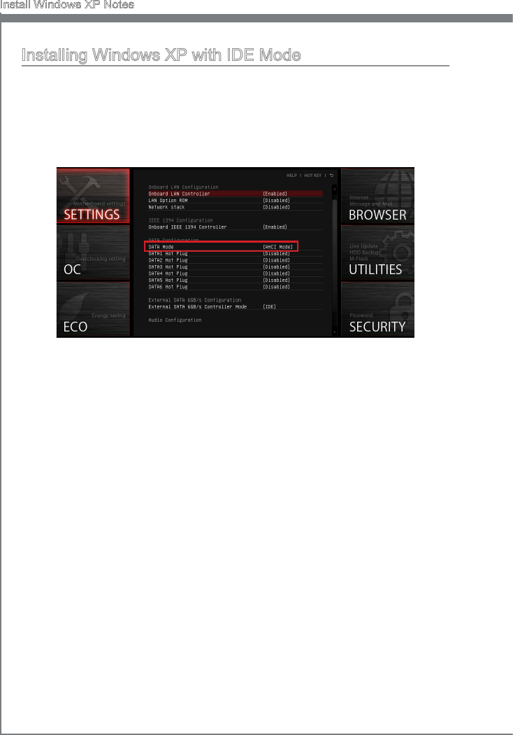
C-2
Install Wndows XP Notes
Installng Wndows XP wth IDE Mode
You wll fal and encounter a blue screen whle nstallng Wndows XP, because t s
not natvely supported to be nstalled n the storage devce wth AHCI mode. If you stll
prefer to nstall Wndows XP as the operatng system, please change the BIOS tem as
below.
Refer to Chapter 2 to access BIOS.
Go to SETTINGS → Integrated Perpherals → SATA Mode.
1.
2.
Set ths tem to IDE mode.
Go to SETTINGS → Save & Ext → Save changes and reboot.
Install the Wndows XP operatng system.
3.
4.
5.
C-3
MS-7758
Appendx C
Installng Wndows XP wth AHCI Mode
If you prefer to nstall Wndows XP as the operatng system wth AHCI mode, please
prepare AHCI drvers for Wndows XP n advanced.
Creatng a Intel AHCI Drver Dsc
Please follow the nstructon below to make an “AHCI Drver” for yourself.
Insert the MSI DVD nto the DVD-ROM drve.
Clck the “Browse CD” on the Setup screen.
Copy all the contents from \\Storage\Intel\PCH 7\f6py-x86 or f6py-x64 to a
formatted oppy dskette.
The drver dskette s done.
Important
You can download the drver from
http://download3.ms.com/les/downloads/dvr_exe/ntel7x_rst_oppy_mb.zp
Installng the Wndows XP Operatng System:
Please follow the below steps:
Access BIOS, set SATA Mode to AHCI mode, save, ext and reboot.
Ensure the USB Floppy Dsk Drve s connected to the computer.
Install Wndows XP. When Wndows Setup screen appears a message “Press F6 f
you need to nstall a thrd party SCSI or RAID drver....”, press “F6” key.
Insert the oppy dsk contanng the AHCI drvers nto the oppy dsk drve.
When the next screen appears, press the “S” key to specfy an addtonal devce.
From the provded lst, select the Intel(R) 7 Seres SATA AHCI Controller.
Follow the on-screen nstructons to complete the nstallaton.
■
■
■
■
1.
2.
3.
4.
5.
6.
7.

Intel® Small Busness Advantage (Intel® SBA) provdes
an out-of-the-box hardware-based securty and produc-
tvty sute desgned for the small busness user. Intel
SBA ncludes a customzable user nterface and several
bundled Intel applcatons.
Appendx D
Intel SBA
D-2
Intel SBA
Prerequstes
Supported Operatng Systems
Intel SBA supports followng OS:
Wndows 7 Professonal 64-bt and 32-bt
Wndows 7 Enterprse 64-bt
Requred User Permssons
You must run the nstaller and the customzaton wzard wth a user that has local ad-
mnstrator permssons on the computer.
Wndows Update Settngs
In certan condtons, the Wndows Update task n the PC Health Center applcaton s
dsabled and cannot be enabled. Ths can occur f Intel SBA s nstalled on a computer
where Wndows Update was dsabled durng nstallaton of the Wndows operatng sys-
tem. The Wndows Update task s shown n the GUI but s grayed out (dsabled). Even
f the end user enables Wndows Update n the operatng system, the PC Health Center
task cannot be enabled. Ths means that the end user cannot use PC Health Center to
manage Wndows Update.
To prevent ths, make sure that you do NOT select the Never check for updates opton
when nstallng the Wndows operatng system.
Wndows Task Scheduler
Some PC Health Center tasks are applcatons that can also be used drectly from the
operatng system and scheduled va the Wndows Task Scheduler. When a task s set
va PC Health Center, an alarm clock s set that wll wake up the computer f t s turned
o. Denng a scheduled tme for an applcaton/task outsde of PC Health Center does
not set an alarm clock. Ths means that the computer wll not be woken up to do the
task.
For ths reason, t s NOT recommended to dene schedules for these applcatons:
Wndows Updates
Wndows Backup and Restore
Dsk defragmentaton
Instead, let the end user set the schedule for all these tasks va PC Health Center.
■
■
■
■
■
■
■
■
■
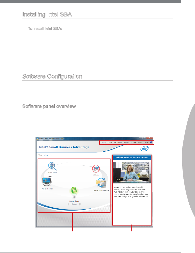
D-3
MS-7758
Appendx D
Installng Intel SBA
Ths procedure descrbes how to nstall Intel SBA.
To nstall Intel SBA:
Logon to the computer wth a user that has admnstrator prvleges.
Insert the applcaton DVD nto the DVD-ROM drve. The setup screen wll automat-
cally appear.
Clck OTHERS tab.
Select Intel SBA to start nstallng.
Follow the on-screen nstructons to nstall.
Software Conguraton
After nstallaton of the Intel SBA software s complete, the Intel SBA servce s started.
The desktop, system tray, and programs menu nclude shortcuts to the GUI of Intel
SBA.
Software panel overvew
The followng gure descrbes the functon of the Intel SBA control panel.
■
1.
2.
3.
4.
5.
Tabs Selecton
Applcatons Selecton Applcatons Descrpton
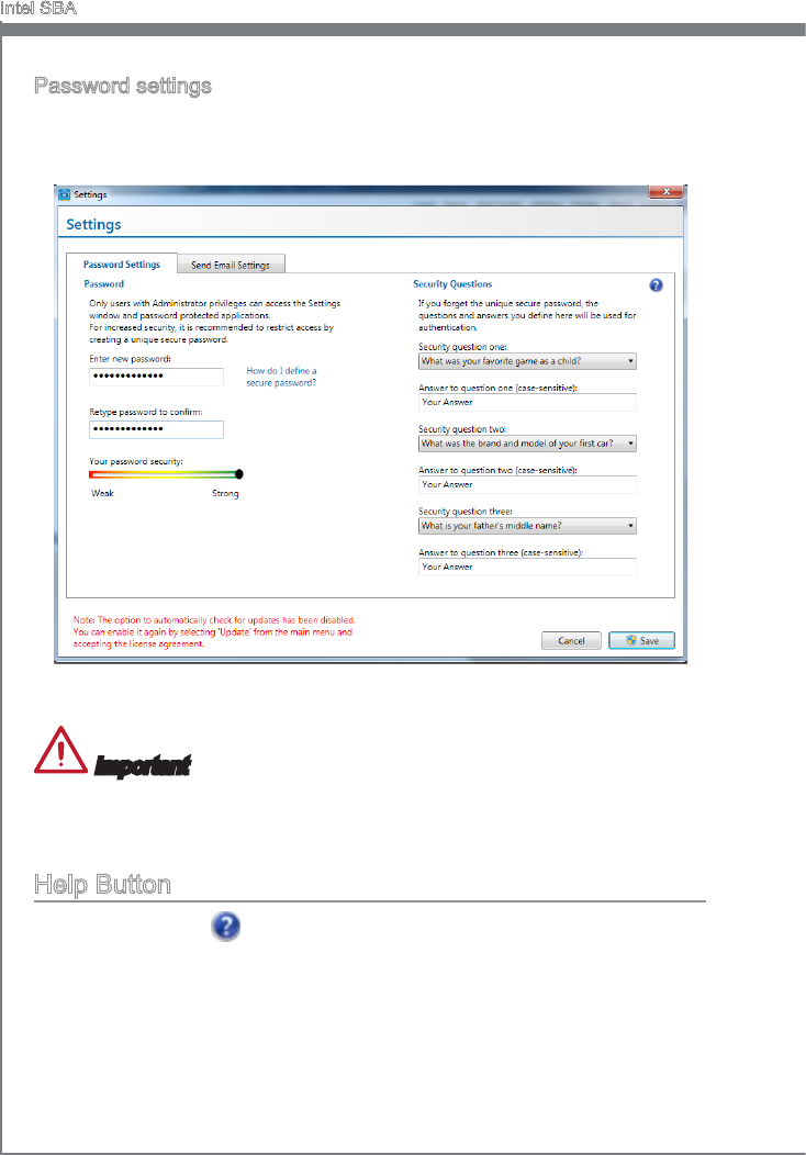
D-4
Intel SBA
Password settngs
By default, the system s n an uncongured state. Before the hardware capabltes can
be used by Intel SBA software, the system must be congured. Ths s done n the Set-
tngs > Password Settngs tab n the man menu of the GUI.
Fll out the form to create the new password and clck “Save”. You wll be asked to enter
the password when you want to start usng Intel SBA.
Important
Upon completon of the password settngs, please keep your password secure.
Please remember your answers to the securty questons.
Help Button
There s a help button on the top rght. If you need to know detaled ntroductons.
Just clck on the help button, to get the nformaton.
•
•
