Mueller Systems HOTRODV2PL AMR Transmitter User Manual 12 0115 Exhibit Cover B
Mueller Systems, LLC AMR Transmitter 12 0115 Exhibit Cover B
Manual

5015 B.U. Bowman Drive Buford, GA 30518 USA Voice: 770-831-8048 Fax: 770-831-8598
Certification Exhibit
FCC ID: SM6-HOTRODV2PL
IC: 9235A-HOTRODV2PL
FCC Rule Part: 15.249
IC Radio Standards Specification: RSS-210
ACS Project Number: 12-0115
Manufacturer: Mueller Systems
Model: AHRPL-DL
Manual

HOTRODV2
Installation Manual
PN 880-0083-001
Rev 0.8
HOTRODV2 INSTALLATION MANUAL
Page ii Mueller Systems, LLC Rev 0.8
Document Information
Title:
HOTRODV2 Installation Manual
Version:
0.8
Created:
11/15/11
Last Modified On:
5/24/2012 7:26 AM
Author:
Technical Lead:
Contributors:
Revision History
Version
Date
Author
Comments
Reviewers
Reviewed By
Title
Date Reviewed

HOTRODV2 Installation Manual
Mueller Systems, LLC Page iii
Table of Contents
1. Introduction .............................................................................................. 1
2. Product Features ....................................................................................... 1
3. CONNECTING AND OPERATING THE MUELLER AMR TRANSMITTER ............ 2
4. AMR TRANSMITTER TROUBLE SHOOTING .................................................. 3
5. FCC INFORMATION .................................................................................... 3
6. IC INFORMATION....................................................................................... 3
Table of Figures
FIGURE 1 ................................................................................................................ 1
FIGURE 2 ................................................................................................................ 2
FIGURE 3 ................................................................................................................ 3

HOTRODV2 INSTALLATION MANUAL
Page iv Mueller Systems, LLC Rev 0.8
FCC Information
Changes or modifications not expressly approved by Mueller Systems,
LLC could void the user's authority to operate the equipment.
IMPORTANT NOTE: To comply with FCC RF exposure compliance
requirements, the antenna used for this transmitter must be installed
to provide a separation distance of at least 20 cm from all persons and
must not be co-located or operating in conjunction with any other
antenna or transmitter.
“NOTE: This equipment has been tested and found to comply with the limits
for a Class B digital device, pursuant to Part 15 of the FCC Rules. These limits
are designed to provide reasonable protection against harmful interference in
a residential installation. This equipment generates, uses and can radiate radio
frequency energy and, if not installed and used in accordance with the
instructions, may cause harmful interference to radio communications.
However, there is no guarantee that interference will not occur in a particular
installation. If this equipment does cause harmful interference to radio or
television reception, which can be determined by turning the equipment off
and on, the user is encouraged to try to correct the interference by one or
more of the following measures:
-- Reorient or relocate the receiving antenna.
-- Increase the separation between the equipment and receiver.
-- Connect the equipment into an outlet on a circuit different from that to which
the receiver is connected.
-- Consult the dealer or an experienced radio/TV technician for help.

HOTRODV2 Installation Manual
Mueller Systems, LLC Page v
IC Information
Under Industry Canada regulations, this radio transmitter may only operate using an
antenna of a type and maximum (or lesser) gain approved for the transmitter by
Industry Canada. To reduce potential radio interference to other users, the antenna type
and its gain should be so chosen that the equivalent isotropically radiated power (e.i.r.p.)
is not more than that necessary for successful communication.
Conformément à la réglementation d'Industrie Canada, le présent émetteur radio peut
fonctionner avec une antenne d'un type et d'un gain maximal (ou inférieur) approuvé
pour l'émetteur par Industrie Canada. Dans le but de réduire les risques de brouillage
radioélectrique à l'intention des autres utilisateurs, il faut choisir le type d'antenne et son
gain de sorte que la puissance isotrope rayonnée équivalente (p.i.r.e.) ne dépasse pas
l'intensité nécessaire à l'établissement d'une communication satisfaisante.
This device complies with Industry Canada licence-exempt RSS standard(s). Operation is
subject to the following two conditions: (1) this device may not cause interference, and
(2) this device must accept any interference, including interference that may cause
undesired operation of the device.
Le présent appareil est conforme aux CNR d'Industrie Canada applicables aux appareils
radio exempts de licence. L'exploitation est autorisée aux deux conditions suivantes : (1)
l'appareil ne doit pas produire de brouillage, et (2) l'utilisateur de l'appareil doit accepter
tout brouillage radioélectrique subi, même si le brouillage est susceptible d'en
compromettre le fonctionnement.
HOTRODV2 Installation Manual
Mueller Systems, LLC Page 1
1. Introduction
This document is intended to assist professional installers with Mueller Systems AMR
transmitters. It provides instructions on how to successfully connect, operate, and
troubleshoot the transmitters. Mueller’s remote meter reading transmitters were
designed with an “easy to install approach” for utilities. The AHRAG-DL, AHRPL-DL, and
AHRML-DL allow the utility to receive data from any Mueller water meter equipped with a
Translator register. The transmitter collects data from the register and transmits it via
radio frequency (RF) to be collected by a mobile receiver.
2. Product Features
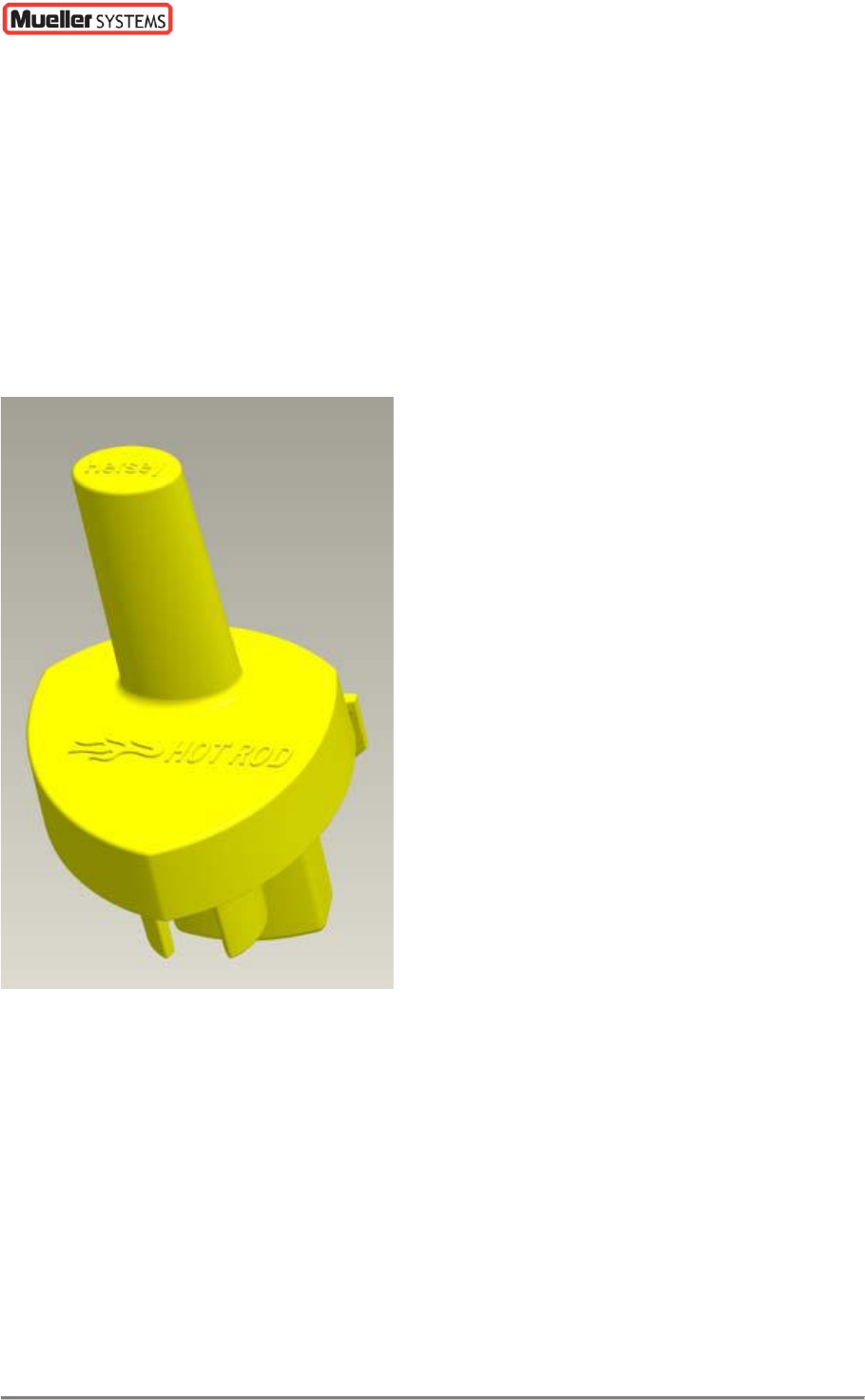
Figure 1
The thermoplastic housing design reduces material and helps eliminate air space within
the transmitter, Figure 1. Mounting features include two holes for wall installation and a
1/2 inch female PVC pipe fitting for easy pit installation. The transmitter units are
molded from grey plastic. The high power unit should only be used within a metal meter
box. The medium power unit should only be used within a plastic meter box. The low
power unit should only be used outside a meter box. A quarter wavelength whip antenna
is utilized. A primary lithium battery is utilized to power the device. The device will
transmit readings every three seconds, but that value is configurable at the factory. The
electronic design utilizes the latest in RF microchip technology which reduces cost and
increases reliability when compared to older RF designs. In order to protect the AMR
transmitter from moisture ingress, the design incorporates the use of thermoplastic
injection molded housings, rubber seals, a potting compound that completely encases the
internal electronics and a coated circuit board which provides the final barrier of
protection. Internal wire strain relief has been built into the housing to protect the wire
HOTRODV2 INSTALLATION MANUAL
Page 2 Mueller Systems, LLC Rev 0.8
connections against damage. Please note that this does not mean meters or registers
can be carried while supported only by the AMR transmitter or wiring.
3. CONNECTING AND OPERATING THE MUELLER AMR
TRANSMITTER
The AMR transmitter is preprogrammed prior to being attached to the meter. All pit set
units come with either 5’ or 25’ of wire attached and potted at the factory as specified. If
a retro fit is required, the wires should be spliced to the existing wires coming from the
register. Wire the red to red, green to green, and black to black wires using 3M UY2
Scotchlok splices with the E-9Y application tool.
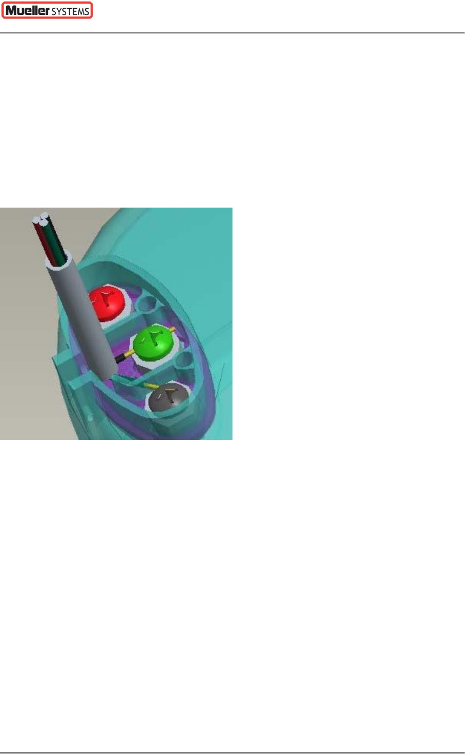
Figure 2
If a new wall unit is being installed it can be directly mounted to any surface by using the
holes shown in Figure 2 and the appropriate screws. New pit installations can use the
mounting method described above or a ½” PVC pipe can be used in conjunction with the
PVC Installation Slot shown in Figure 2. This feature allows for quick easy installation
without the use of zip ties, wraps, tape, or adhesives. Two solid stops were included in
the PVC Installation Slot in order to prevent the wire from being pinched when the PVC
pipe is installed. For best performance the top of the transmitter should be placed
approximately six inches below the pit lid. A TRU-Readremote display can be used in
conjunction with the Translator register and AMR transmitter for visual remote readings if
desired. Refer to TRU-Read installation instructions below to attach both devices. When
wiring the TRU-Read to the Translator you must connect the red wire to the red terminal,
the green to green, and the black to black, Figure 2.
HOTRODV2 Installation Manual
Mueller Systems, LLC Page 3
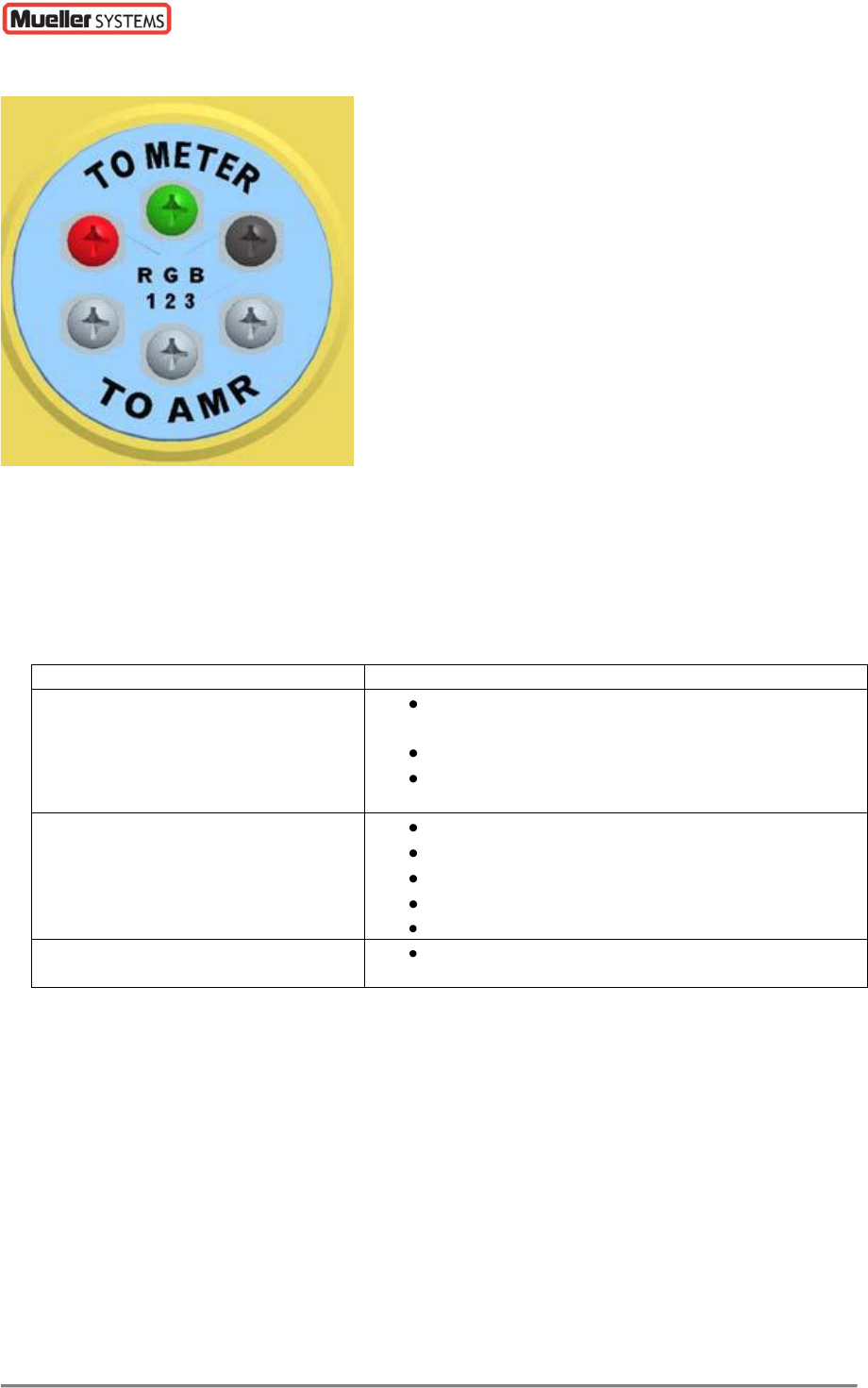
Figure 3
To attach the AMR transmitter, wire the red wire to terminal #1, the green wire to #2,
and the black wire to terminal #3 on the TRU-Read,Figure 3. Once the transmitter is
attached it will begin sending out data automatically. Please note that Mueller Systems
AMR transmitter and TRU-Read should never be disassembled or user serviced.
4. AMR TRANSMITTER TROUBLE SHOOTING
PROBLEM
POSSIBLE CAUSE
POOR RANGE
CHECK ORIENTATION OF THE HOT
ROD ANTENNA
CHECK THE RECEIVER ANTENNA
CHECK FOR INTERFERENCE
NOT TRANSMITTING
CORRECT DATA
CHECK WIRING CONNECTIONS
CHECK WIRES FOR SHORT
CHECK FOR INTERFERENCE
CHECK DISTANCE TO RECEIVER
CHECK TRANSLATOR STATUS
NOT TRANSMITTING
CHECK POWER ON AMR TRANSMITTER
5. FCC INFORMATION
The AMR transmitters operate in the license exempt 902 MHz to 928 MHz ISM band and
are certified for operation in the US under FCC Part 15. The FCC IDs are SM6-
HOTRODV2ML, SM6-HOTRODV2PL, and SM6-HOTRODV2AG. Information pertaining to
their certification can be found on the web at WWW.FCC.GOV.
6. IC INFORMATION
The AMR transmitters operate in the license exempt 902 MHz to 928 MHz ISM band and
are certified for operation in Canada. The IC IDs are 9235A-HOTRODV2ML, 9235A-
HOTRODV2PL, and 9235A-HOTRODV2AG. Information pertaining to their certification
can be found on the web at http://www.ic.gc.ca/eic/site/ceb-bhst.nsf/eng/home.