Mueller Systems MINODE-M Automatic Metering and Control Device User Manual Installation Manual
Mueller Systems, LLC Automatic Metering and Control Device Installation Manual
UserManual.wiki
>
Mueller Systems
>
MINODE-M User Manual
>
Installation Manual
Contents
1.
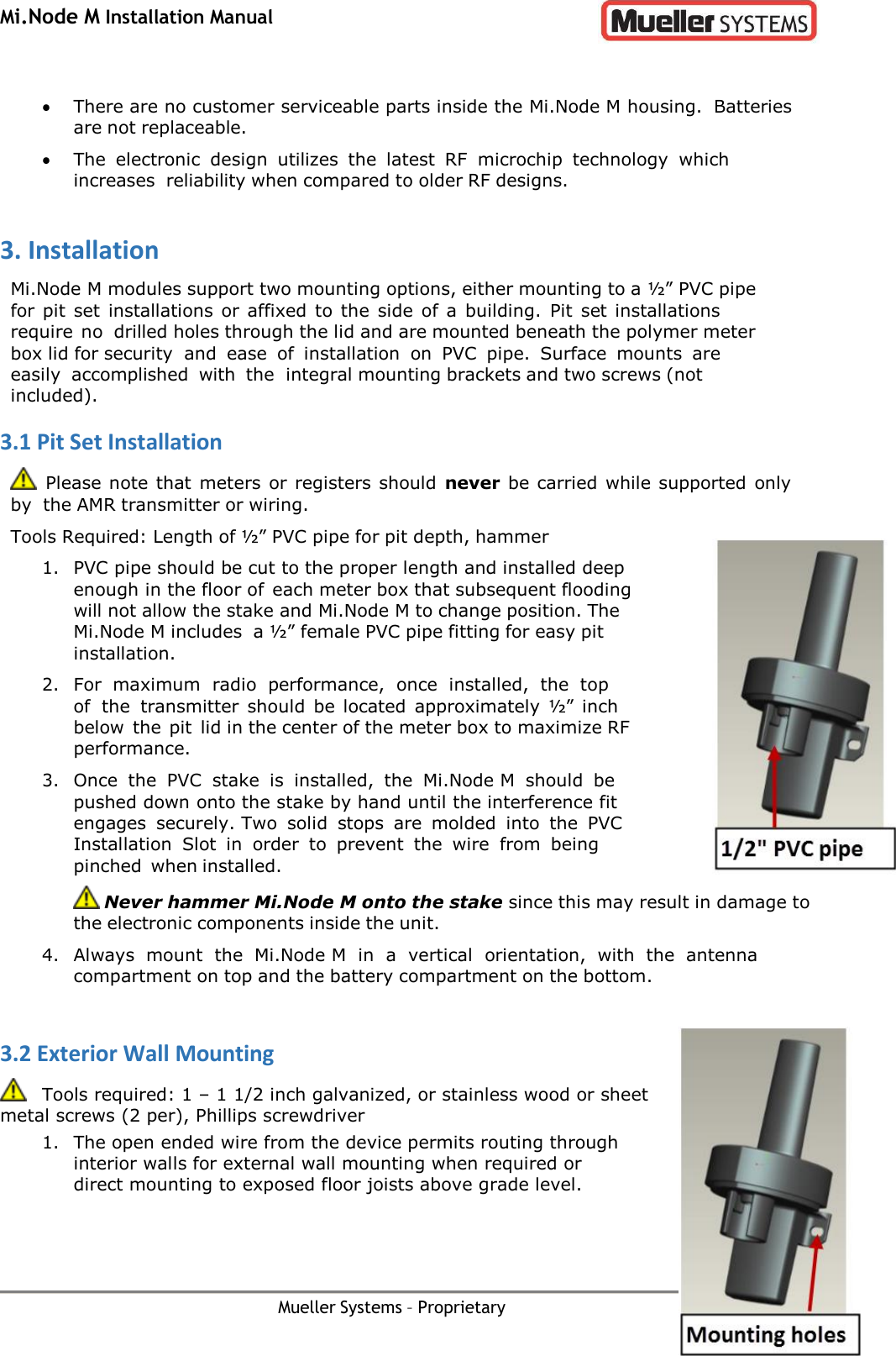
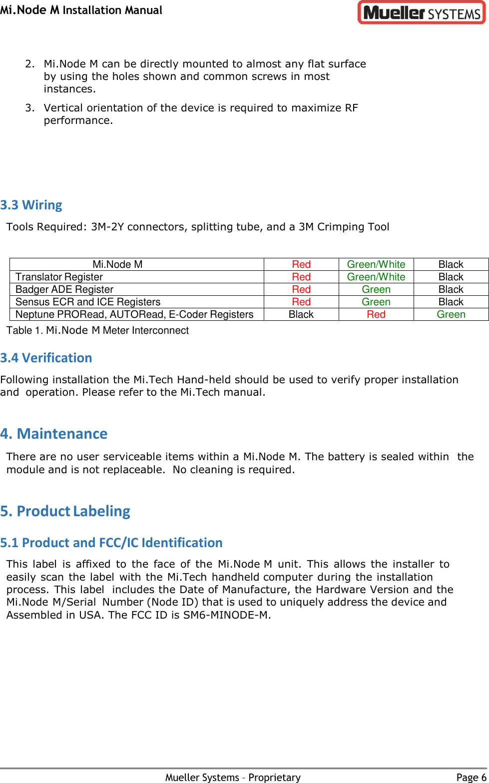
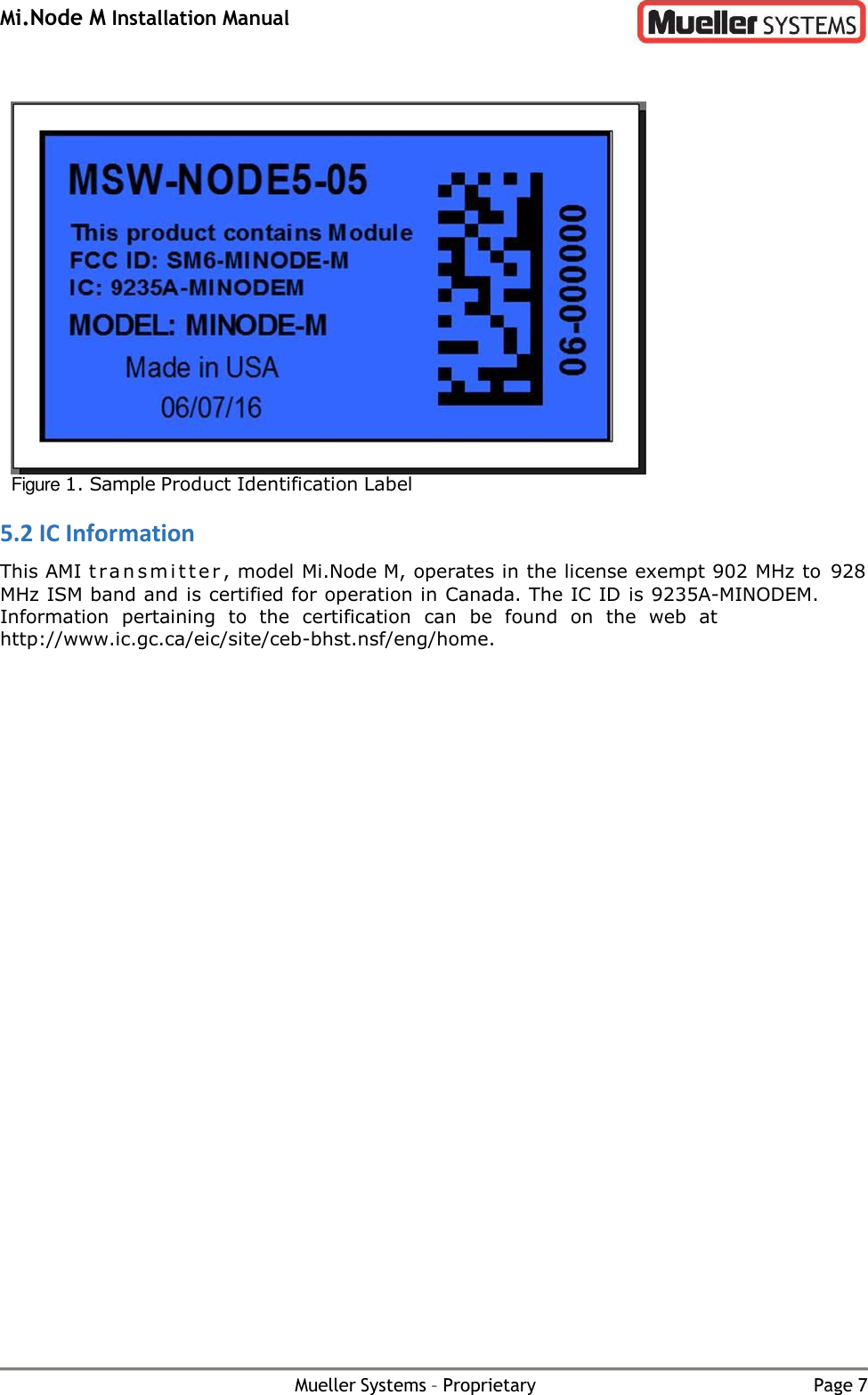
Installation Manual
2.
User Manual
Installation Manual
Navigation menu
Upload a User Manual
Namespaces
Wiki Guide
HTML
PDF
Info
Views
User Manual
Discussion / Help
Navigation