Mueller Systems MINODE-WATER4 DCOM4 Transmitter User Manual 15 0006 Exhibit Cover
Mueller Systems, LLC DCOM4 Transmitter 15 0006 Exhibit Cover
Manual

5015 B.U. Bowman Drive Buford, GA 30518 USA Voice: 770-831-8048 Fax: 770-831-8598
Certification Exhibit
FCC ID: SM6-MINODE-WATER4
IC: 9235A-MINODE4
FCC Rule Part: 15.247
IC Radio Standards Specification: RSS-210
ACS Project Number: 15-0006
Manufacturer: Mueller Systems, LLC
Model: MiNODE-WATER4

MINODE–WATER4
Installation Manual

MINODE–WATER4 Installation Manual
Mueller Systems – Proprietary Page 2
Table of Contents
1. Introduction .................................................................................................. 4
2. Construction .................................................................................................. 4
3. Installation .................................................................................................... 5
3.1 PIT SET INSTALLATION ......................................................................................... 5
3.2 EXTERIOR WALL MOUNTING ................................................................................... 5
3.3 WIRING ........................................................................................................... 5
3.4 VERIFICATION .................................................................................................... 6
4. Maintenance .................................................................................................. 6
5. Product Labeling ............................................................................................ 6
5.1 PRODUCT AND FCC/IC IDENTIFICATION ..................................................................... 6
5.2 FCC CLASS B IDENTIFICATION ..................................... ERROR! BOOKMARK NOT DEFINED.
5.3 IC INFORMATION ............................................................................................ 6
Table of Tables
TABLE 1. MI.NODE - WATER METER INTERCONNECT ................................................................. 6
Table of Figures
FIGURE 1. PRODUCT IDENTIFICATION LABEL ........................................................................... 6

MINODE–WATER4 Installation Manual
Mueller Systems – Proprietary Page 3
FCC Information:
Changes or modifications not expressly approved by the Mueller Systems could
void the user's authority to operate the equipment.
IMPORTANT NOTE: To comply with FCC RF exposure compliance
requirements, the antenna used for this transmitter must be installed to
provide a separation distance of at least 20 cm from all persons and must not
be co-located or operating in conjunction with any other antenna or
transmitter.
This device complies with part 15 of the FCC Rules. Operation is subject to the
following two conditions: (1) This device may not cause harmful interference, and (2)
this device must accept any interference received, including interference that may
cause undesired operation.
“NOTE: This equipment has been tested and found to comply with the limits for a
Class B digital device, pursuant to Part 15 of the FCC Rules. These limits are
designed to provide reasonable protection against harmful interference in a
residential installation. This equipment generates, uses and can radiate radio
frequency energy and, if not installed and used in accordance with the
instructions, may cause harmful interference to radio communications. However,
there is no guarantee that interference will not occur in a particular installation. If
this equipment does cause harmful interference to radio or television reception,
which can be determined by turning the equipment off and on, the user is
encouraged to try to correct the interference by one or more of the following
measures:
-- Reorient or relocate the receiving antenna.
-- Increase the separation between the equipment and receiver.
-- Connect the equipment into an outlet on a circuit different from that to which the
receiver is connected.
-- Consult the dealer or an experienced radio/TV technician for help.
IC Information
Under Industry Canada regulations, this radio transmitter may only operate using an
antenna of a type and maximum (or lesser) gain approved for the transmitter by Industry
Canada. To reduce potential radio interference to other users, the antenna type and its gain
should be so chosen that the equivalent isotropically radiated power (e.i.r.p.) is not more
than that necessary for successful communication.
Conformément à la réglementation d'Industrie Canada, le présent émetteur radio peut
fonctionner avec une antenne d'un type et d'un gain maximal (ou inférieur) approuvé pour
l'émetteur par Industrie Canada. Dans le but de réduire les risques de brouillage
radioélectrique à l'intention des autres utilisateurs, il faut choisir le type d'antenne et son
gain de sorte que la puissance isotrope rayonnée équivalente (p.i.r.e.) ne dépasse pas
l'intensité nécessaire à l'établissement d'une communication satisfaisante.
This device complies with Industry Canada licence-exempt RSS standard(s). Operation is
subject to the following two conditions: (1) this device may not cause interference, and (2)
this device must accept any interference, including interference that may cause undesired
operation of the device.
Le présent appareil est conforme aux CNR d'Industrie Canada applicables aux appareils
radio exempts de licence. L'exploitation est autorisée aux deux conditions suivantes : (1)
l'appareil ne doit pas produire de brouillage, et (2) l'utilisateur de l'appareil doit accepter
tout brouillage radioélectrique subi, même si le brouillage est susceptible d'en compromettre
le fonctionnement.
MINODE–WATER4 Installation Manual
Mueller Systems – Proprietary Page 4
1. Introduction
The Mueller Systems MINODE-WATER4 is intended for indoor and outdoor use as an
unattended Automatic Metering Infrastructure (AMI) and control device. The MINODE-
WATER4 is fully self-contained and battery powered device with no user accessible controls.
The MINODE-WATER4 for Residential Metering (“MINODE-
WATER4”) is a device that incorporates a microcontroller,
915MHz ISM band transceiver (simplex operation), and battery
(DC power supply) for the purpose of logging and forwarding
water meter readings to the Mueller Systems servers. The
readings are forwarded to server via. other MINODE-WATER4,
MIHUBs, or SmartMeter at assigned times. The MINODE-WATER4
will also autonomously send messages to the server when
various events or alert conditions, such as potential leak or theft
of service, are detected.
Meter reading interval is remotely settable. Information retrieved from the meters registers
are temporarily stored within the MINODE-WATER4’s solid-state memory. On a specified
interval, the MINODE-WATER4 will automatically transmit this information to the Mueller
Systems AMI server via other meters or MIHUBs using the Radio Frequency (RF) network.
The Mueller Systems AMI server analyzes and archives the readings.
The contents of this installation manual are intended for technically qualified personnel of
water and energy distribution utilities who have been trained and are technically qualified in
local safety procedures for installation of the device.
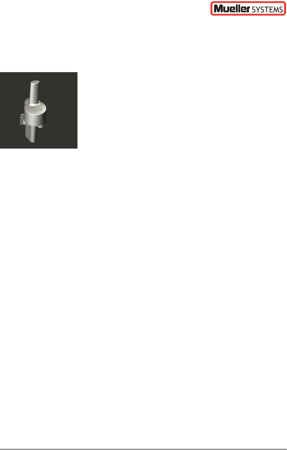
2. Construction
The MINODE-WATER4 product consists of a printed circuit board which is encapsulated to
provide complete protection against shock and water intrusion. The enclosure is made of UV
stable, high density thermoplastic and is completely waterproof. The UV stable,
thermoplastic housing design provides a compact, waterproof enclosure that is lightweight
and easy to handle and install. The MINODE-WATER4 has integral mounting brackets for
both pit and wall installations. One C size lithium battery provides plenty of power for
reading the register and sending RF data.
In order to protect the AMI device electronics from moisture ingress the design
incorporates the use of thermoplastic injection molded housings, rubber seals, a
potting compound that completely incases the internal electronics and a coated
circuit board which combine to provide a formidable barrier of protection against
water intrusion.
Internal wire strain relief has been built into the housing to protect the wire
connections against damage. Please note that meters or registers should never be
carried while supported only by the MINODE-WATER4 transmitter or wiring.
A monopole antenna is located in the upper housing to provide powerful RF
communication.
A single C cell long life Lithium battery is located in the lower housing which provides
power for register interrogation and data transmission for a calculated battery life of
up to 20 years.
There are no customer serviceable parts inside the MINODE-WATER4 housing.
Batteries are not replaceable.
The electronic design utilizes the latest RF microchip technology which increases
reliability when compared to older RF designs
MINODE–WATER4 Installation Manual
Mueller Systems – Proprietary Page 5
3. Installation
MINODE-WATER4 modules support two mounting options, either mounting to a ½” PVC pipe
for pit set installations or affixed to the side of a building. Pit set installations require no
drilled holes through the lid and are mounted beneath the polymer meter box lid for security
and ease of installation on PVC pipe. Surface mounts are easily accomplished with the
integral mounting brackets and two screws (not included).
3.1 Pit Set Installation
Please note that meters or registers should never be carried while supported only by
the AMR transmitter or wiring.
Tools Required: Length of ½” PVC pipe for pit depth, hammer
1. PVC pipe should be cut to the proper length and installed deep enough in the floor of
each meter box that subsequent flooding will not allow the stake and
MINODE-WATER4 to change position. The MINODE-WATER4 includes
a ½” female PVC pipe fitting for easy pit installation.
2. For maximum radio performance, once installed, the top of the
transmitter should be located approximately ½” inch below the pit
lid in the center of the meter box to maximize RF performance.
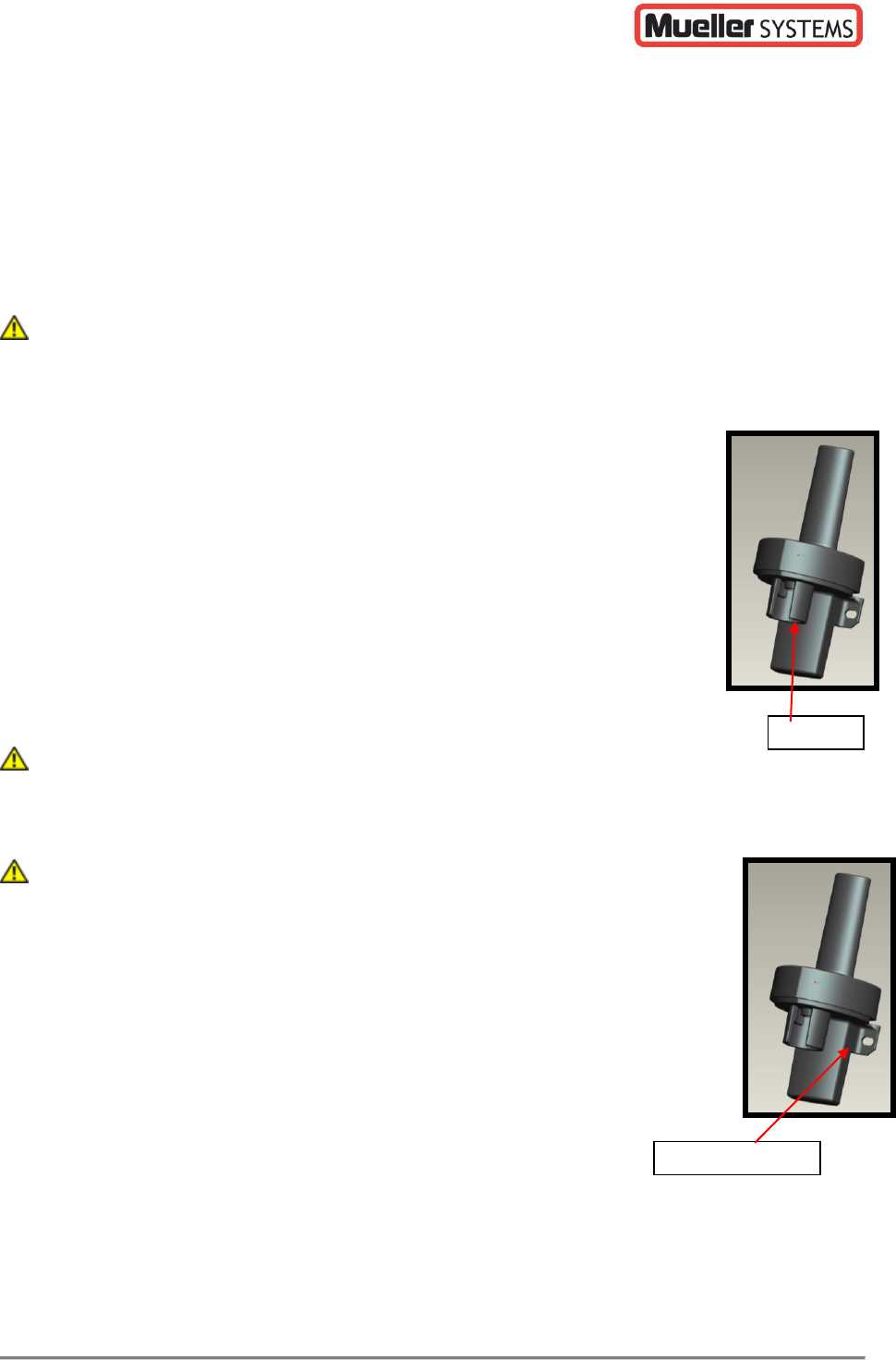
3. Once the PVC stake is installed, the MINODE-WATER4 should be
pushed down onto the stake by hand until the interference fit
engages securely, two solid stops are molded into the PVC
Installation Slot in order to prevent the wire from being pinched
when installed.
4. Always mount the MINODE-WATER4 in a vertical orientation, with the antenna
compartment on top and the battery compartment on the bottom.
Never hammer MINODE-WATER4 onto the stake since this may result in damage to
the electronic components inside the unit.
3.2 Exterior Wall Mounting
Please note that meters or registers should never be carried while
supported only by the AMR transmitter or wiring.
Tools Required: 1 – 1 1/2 inch Galvanized, or Stainless Wood or Sheet Metal
Screws (2 per), Phillips Screwdriver
1. The open ended wire from the device permits routing through interior
walls for external wall mounting when required or direct mounting to
exposed floor joists above grade level.
2. MINODE-WATER4 can be directly mounted to almost any flat surface
by using the holes shown and common screws in most instances.
3. Orientation of the device vertically is required to maximize RF
performance.
3.3 Wiring
Tools Required: 3M-2Y connectors, splitting tube, and a 3M Crimping Tool
½” PVC
Installa
tion
Slot
Mounting Holes
Installation Slot
MINODE–WATER4 Installation Manual
Mueller Systems – Proprietary Page 6
MINODE-WATER4
Red
Green/White
Black
Translator Register
Red
Green/White
Black
Badger ADE Register
Red
Green
Black
Sensus ECR and ICE Registers
Red
Green
Black
Neptune PRORead, AUTORead, E-Coder Registers
Black
Red
Green
Table 1. MI.NODE - WATER Meter Interconnect
3.4 Verification
Following installation the Mi.Tech Hand-held should be used to verify proper installation and
operation. Please refer to the Mi.Tech manual.
4. Maintenance
There are no user serviceable items within a MINODE-WATER4. The battery is sealed within
the module and is not replaceable. No cleaning is required.
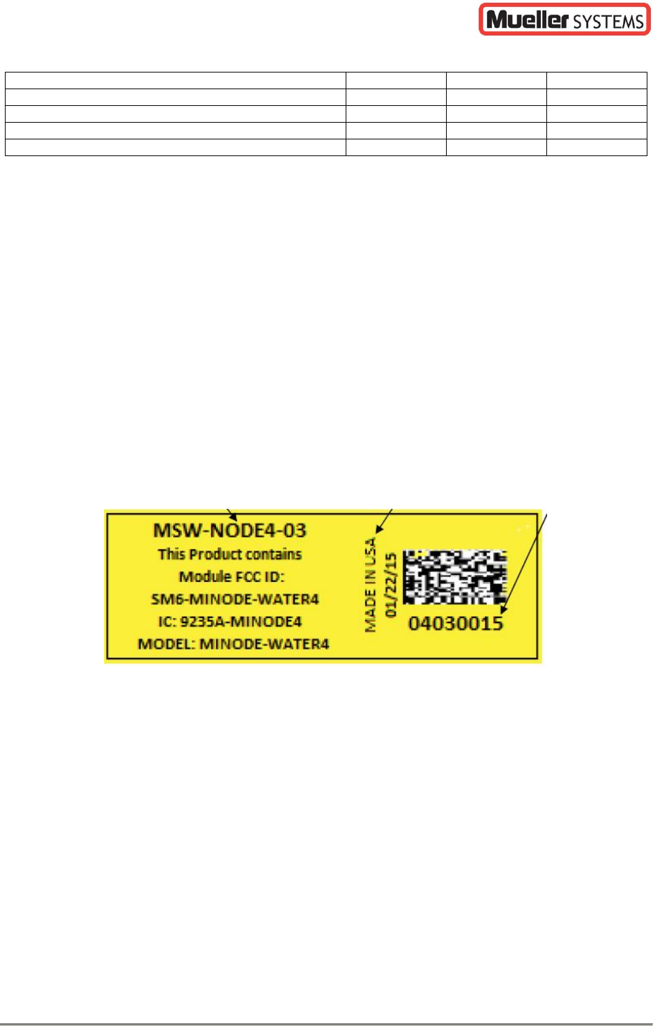
5. Product Labeling
5.1 Product and FCC/IC Identification
This label is affixed to the face of the MINODE-WATER4 unit. This allows the installer to
easily scan the label with the Mi.Tech hand-held during the installation process. This label
includes the Date of Manufacture, the Hardware Version and the MI.NODE–WATER4 /Serial
Number (Node ID) that is used to uniquely address the device and Assembled in USA.
Figure 1. Product Identification Label
5.2 IC INFORMATION
This AMI transmitter, model MINODE-WATER4, operates in the license exempt 902 MHz to
928 MHz ISM band and is certified for operation in Canada. The IC ID is 9235A-MINODE4.
Information pertaining to the certification can be found on the web at
http://www.ic.gc.ca/eic/site/ceb-bhst.nsf/eng/home.