Multi Tech Equipment Mta128St Users Manual
MTA128ST to the manual 4a6fc1b7-6ebc-4f52-9b83-53c68d360dc5
2015-02-09
: Multi-Tech-Equipment Multi-Tech-Equipment-Mta128St-Users-Manual-557936 multi-tech-equipment-mta128st-users-manual-557936 multi-tech-equipment pdf
Open the PDF directly: View PDF ![]() .
.
Page Count: 61

Models MTA128ST and MTA128NT
External ISDN Terminal Adapter
User Guide

2
User Guide
Model MTA128ST/NT
S000305C Rev. C
This publication may not be reproduced, in whole or in part, without prior written permission from Multi-Tech Systems,
Inc. All rights reserved.
Copyright © 2004- 07 by Multi-Tech Systems, Inc.
Multi-Tech Systems, Inc. makes no representations or warranties with respect to the contents hereof and specifically
disclaims any implied warranties of merchantability or fitness for any particular purpose. Furthermore, Multi-Tech
Systems, Inc. reserves the right to revise this publication and to make changes from time to time in the content
hereof without obligation of Multi-Tech Systems, Inc. to notify any person or organization of such revisions or
changes.
Revision Date Description
A 7/25/03 The manual replaces 82052305 Rev. G. Manual updated with NT info. AT commands
and S registers moved into additional documentation on CD.
B 11/05/04 Changed temperature from -50 to-40 C.
C 09/06/07 Update tech support contact list.
Trademarks
IWay, IWay Hopper, Multi-Tech, and the Multi-Tech logo are trademarks of Multi-Tech Systems, Inc. AT&T and
5ESS are registered trademarks of American Telephone and Telegraph. Microsoft, Windows, and Windows 95 are
registered trademarks of Microsoft Corporation. NETCOM is a registered trademark of NETCOM On-Line
Communication Services, Inc. Netscape and Navigator are trademarks of Netscape Communications Corp.
DMS-100 is a trademark of Northern Telecom. All other trademarks are owned by their respective companies.
Multi-Tech Systems, Inc.
2205 Woodale Drive
Mounds View, MN 55112
U.S.A
Telephone (763) 785-3500 or (800) 328-9717
Fax (763) 785-9874
Technical Support (800) 972-2439
Internet http://www.multitech.com

Contents
3
Contents
Chapter 1: Introduction and Description ........................................................................................................................4
Welcome to the world of ISDN communications. ................................................................................................................ 4
Product Description.............................................................................................................................................................. 4
Features............................................................................................................................................................................... 5
LED Indicators .................................................................................................................................................................... 8
Technical Specifications ...................................................................................................................................................... 10
Chapter 2: Hardware Installation .....................................................................................................................................11
Safety Warnings .................................................................................................................................................................. 11
Connecting your TA ............................................................................................................................................................. 11
Chapter 3: Configuration Utilities ...................................................................................................................................13
Introduction ......................................................................................................................................................................... 13
Before You Start ................................................................................................................................................................. 13
Configuring your TA ............................................................................................................................................................. 17
Chapter 4: AT Commands, S-Registers, and Result Codes..........................................................................................26
MTA128ST/NT Commands and S-Registers ...................................................................................................................... 26
S-Registers ......................................................................................................................................................................... 29
Chapter 5: Troubleshooting..............................................................................................................................................34
Troubleshooting the TA........................................................................................................................................................ 34
Chapter 6: Point-to-Point Communications: PPP/MLPPP.............................................................................................41
Chapter 7: Warranty, Service, and Tech Support...........................................................................................................44
Multi-Tech Systems, Inc. Warranty & Repairs Policies .......................................................................................................44
Online Warranty Registration .............................................................................................................................................. 45
Service ................................................................................................................................................................................. 45
Replacement Parts .............................................................................................................................................................46
Technical Support ............................................................................................................................................................... 47
Appendix A:Configuration Profiles..................................................................................................................................48
Quick Setup Factory Profiles .............................................................................................................................................. 48
Quick Setup Example ......................................................................................................................................................... 48
Appendix B: Ordering Your ISDN Line ...........................................................................................................................49
Loop Qualification ...............................................................................................................................................................49
Bearer Service ..................................................................................................................................................................... 50
Using ISDN Ordering Codes (IOCs) .................................................................................................................................... 50
Ordering ISDN Without IOCs...............................................................................................................................................52
Appendix C: FCC and Canadian Regulation ..................................................................................................................56
FCC......................................................................................................................................................................................56
Canadian Limitations Notice ................................................................................................................................................ 57
Appendix D: Configuration Methods ...............................................................................................................................58
Firmware-based Configuration Utility................................................................................................................................... 58
Configuration via AT Commands.........................................................................................................................................58
Glossary..............................................................................................................................................................................59
Index....................................................................................................................................................................................65

Introduction and Description
4
Chapter 1: Introduction and Description
Welcome to the world of ISDN communications.
You have acquired one of the finest ISDN terminal adapters (TAs) available today, model MTA1 28ST/NT
from Multi-Tech Systems. The MTA128ST is a desktop TA with an S/T interface port to connect itto the
ISDN network and an analog port to connect it to a telephone, modem, or fax machine. The MTA1 28NT is a
desktop TA with a U-interface to connect it to the ISDN network and an analog port to connect it to a
telephone, modem, or fax machine. The TAs ship with a software configuration utility for Windows® 98/NT/
ME, and ConfigMenu, a built-in configuration utility for Windows and non-Windows operating systems. In
addition, the MTA128ST/NT accepts AT commands that enable itto use the same communications
software as an analog modem.
The MTA128ST is compatible with the popular EuroISDN switch protocol, it communicates using ISDN
BRI (2B+D) service, which provides up to 128 Kbps data and voice communications, and it automatically
detects whether an incoming call is voice or data and handles it appropriately.
The MTA128ST/NT provides dial-up asynchronous communication capability with other personal
computers, terminals, on-line computer services, or other computer systems. Connection to your
computer/terminal device is made via the RS232 connector (ISDN). Connection to analog devices is
accomplished with an RJ1 1 connector and one RJ45 connector is used for your ISDN connection.
This User Guide will help you install, configure, and operate your MTA128ST/NT.
Product Description
There are two ISDN interface options, S/T and U. If you purchased the S/T interface adapter
(MTA128ST), you need an ISDN NT1 device connection to the ISDN switch. If you purchased the U
interface adapter (MTA1 28NT), it can directly connect to the ISDN switch (figure 1-1).
Figure 1-1. ”S/T” and “U” Interface Options

Introduction and Description
5
Your ISDN TA is compatible with prevalent ISDN switch protocols. It communicates using ISDN BRI
(2B+D) service, which provides up to 128K bps data communications. This manual documents the
following models:
• MTA1 28ST for S/T interface with one POTS port
• MTA1 28NT for U interface with one POTS port
Some analog devices, including telephone set, answering machine, and modem, can be connected to the
POTS port via an RJ-1 1 jack.
This User Guide will help you install, configure, and operate your terminal adapter.
Features
The MTA128ST/NT communicates over public ISDN telephone lines. Features include:
• Compatibility with EuroISDN (ETSI/DSS1/NET3), French VN4, and Japanese INS64 switch protocols
• Compatibility with U.S. NI-1, AT&T 5ESS, and DMS-100 switch protocols
• Compatibility with V.120, ML-PPP, and X.75 protocols
• Transparent synchronous communication capability (CLEAR)
• ISDN BRI (2B+D) and analog ports
• RS232E serial port
• Serial port speeds to 460.8 Kbps
• Support of PPP (Point-to-Point Protocol) for high speed ISDN connections
• Tone detection to allow use of a standard telephone for ISDN line access (an ISDN telephone is not
required)
• Automatic detection of incoming calls as voice or data
• Windows 98/NT/ME software utility and a firmware utility for easy ISDN line configuration
• AT commands, S-registers, and result codes
• Ability to use the same communications software as analog modems
• Flash memory for easy firmware upgrades
ISDN BRI Line
Before running the ISDN adapter, you need to get an ISDN BRI (Basic Rate Interface) line from your local
telephone company. Your ISDN service provider will provide information to you about the ISDN central
switch type, pertinent subscriber information and SPID (Service Profile ID) number(s) if required.
SPID (Service Profile ID)
The Service Profile ID (SPID) is applicable in the U.S. only. SPIDs are a series of numbers that inform the
central office switch which services and features to provide to an ISDN device. The generic SPID format
comprises 14 digits. The first 10 digits are the main telephone number on the terminal. The last 4 digits
are dependent on the number of terminals on the interface and the services they support.
NT1 Connection
An ISDN Basic Rate (BRI) U-Loop consists of 2 conductors from the CO (telephone company central
office) to the customer premises. The equipment on both sides of the U-loop has been designed to deal with
the long length of the U-loop and the noisy environment it operates in. At the customer premises the U-loop
is terminated by an NT1 (network termination 1) device. An NT1 is a device which provides an interface
between the two-wire twisted-pairs used by telephone companies in their ISDN BRI network and an end-
user's four wire terminal equipment. The NT1 drives an S/T-bus which is usually made up of 4 wires, but in
some cases may be 6 or 8 wires.
The name of the S/T bus comes from the letters used in the ISDN specifications to refer to two reference
points, Sand T. Point Trefers to the connection between the NT1 device and customer supplied
equipment. Terminals can connect directly to NT1 at point T, or there may be a PBX (private branch
exchange, i.e. a customer-owned telephone exchange). When a PBX is present, point S refers to the
connection between the PBX and the terminal. Note that in ISDN terminology, "terminal" can mean any
sort of end-user ISDN devices, such as data terminals, telephones, FAX machines, etc. The diagram
which follows reflects interface points in a typical ISDN network.

Introduction and Description
6
If your ISDN product operates with a S/T outlet interface, you need an NT1 device to connect to the ISDN
switch. MTA128ST adapters need an NT1 device to connect to the ISDN switch, but the MTA128NT
adapter does not require NT1 device. In the UK, and in many European countries, NT1 device is supplied by
your telephone company.
Figure 2-1 ISDN Interface Points
S/T Interlace
The S/T interface uses an 8-conductor modular cable terminated with an 8-pin RJ-45 plug. An 8-pin RJ45
jack located on the terminal is used to connect the terminal to the DSL (Digital Subscriber Loops) using this
modular cable.
Table 2-1 shows the Pin Number, Terminal Pin Signal Name and SILC Pin Signal name for the S/T interface
Pin TE Signal
1 Not used
2 Not used
3 Tx+
4 Rx-
5 Rx+
6 Tx-
7 Not used
8 Not used
U Interlace
The U interface uses a 2-conductor twisted pair cable terminated with an RJ-45 jack. An RJ-45 jack located
on the terminal is used to connect the terminal to the Digital Subscriber Loops using this twisted pair cable.
In Table 2-2 the Pin Number, Terminal Pin Signal Name and UILC Pin Signal Names for the U interface are listed.
Pin
1 N/A
2 N/A
3 N/A
4 Positive Input
5 Negative Input
6 N/A
7 N/A
8 N/A

Introduction and Description
7
LED Indicators
The ten LED indicators on the front panel (see figure below) of the MTA1 28ST/NT report status and line activity.
Transmit Data
Flashes when data is being transmitted (on for a space, off for a mark).
Receive Data
Flashes when data is being received (on for a space, off for a mark). Link
Status
For EuroISDN NET3, INS64, and VN4 switch protocols, lights when the TA is turned on. For US NI-1, DMS-
100, and AT&T 5ESS switch protocols: On Steady, Link with central office is established (requires correct
configuration of SPIDs) Flashing, Physical layer is down or one or both SPIDs have not been verified with
central office
Bearer Channel 1
When lit, indicates active data or voice connection on bearer channel 1.
Bearer Channel 2
When lit, indicates active data or voice connection on bearer channel 2.
Terminal Ready
Lights to indicate that the computer is communicating with the MTA1 28ST/NT, so the MTA1 28ST/NT can
answer an incoming call.
Off Hook
Lights when analog equipment on AUX port is active or off-hook.
128 Kbps
Lights to indicate that the B channels have been multiplexed into a single 128 Kbps communications link.
Data Protocol
Lights in combination with P2 and 128 LEDs to indicate which data protocol (V.110, V. 120, X.75, PPP,
MLPPP) is in use as shown in the table below.
Data Protocol
Lights in combination with P1 and 128 LEDs to indicate which data protocol (V.110, V. 120, X.75, PPP,
MLPPP) is in use as shown in the table below.

Introduction and Description
8
Data Protocol 128 LED P1 LED P2 LED
V.110
V.120
X.75 (1 channel)
PPP (1 channel)
MLPPP (2 channels)
OFF ON

Introduction and Description
9
Technical Specifications
Trade Name Iway Hopper™
Model Number MTA128ST (International),
MTA128NT
Network Interface ST-Four-wire S/T interface
NT-2-wire “U” interface
Switch Compatibiltiy EuroISDN (ETSI/DSS1/NET3), VN4, INS64, U.S. NI-1, AT&T 5ESS,
DMS-100 (both models support all of the switch protocols)
B-Channel Protocols V.120, X.75, PPP, ML-PPP, CLEAR
Voice Coding PCM: A-Law; µ-Law (switch protocol dependent)
LED Indicators 10 front panel LED indicators: Transmit Data, Receive Data, Link Status,
B1 Active, B2 Active, Terminal Ready, Off Hook (AUX port), 128Kbps,
P1 Active (data protocol), P2 Active (data protocol)
Data Rates 300, 1.2K, 4.8K, 9.6K, 38.4K, 56K, 57.6K, 64K, 115.2K, 230.4K, and
460.8K bps
Async Data Format 7 bit data + odd/even parity + 1 start/stop, 8 bit no parity. 36 baud
rate/parity settings via S-register. Baud rates of 300-460.8K bps with
even, space, mark, odd, or no parity.
Data Connections Two ISDN B-channels
One ISDN D channel
One analog port for connecting a standard telephone, modem, or fax
machine.
Command Interface AT commands, S-registers, result codes, ConfigMenu firmware
configuration utility, Windows 98/NT/ME configuation utility, Dail-Up
Networking (DUN)
Connectors ISDN: RJ45 female receptacle, 4-wire S/T (accepts connection cable to
the network provider’s NT1 device) or 2-wire U interface
AUX: RJ11 female receptable, 2-wire voice service
Serial Port: female DB-25 RS232E/V.24
Serial Interfaces ITU-T V.24, EIA/TIA RS232E
Switches Two-position power switch
Power Requirements Two-prong outlet-mounted transformer (included), 240 VAC 50/60 Hz
Dimensions 15.0 cm x 10.7 cm x 2.8 cm (L x W x D)
Environmental Tenperature range 0° - 40° C (32° - 104° F)
Humdidity range 20-90% (noncondensing)
Power Consumption 4 watts
Weight 224 g (8 oz)
Warranty 5 years

Hardware Installation
10
Chapter 2: Hardware Installation
This chapter shows you step-by-step how to set up your MTA1 28ST/NT terminal adapter (TA) to your computer,
power, network terminator, and an auxiliary analog device. Please follow these instructions carefully to avoid
damage to your TA.
Safety Warnings
• Use this product only with UL-listed and CUL-listed computers.
• Never install phone wiring during a lightning storm.
• Never install a phone jack in a wet location unless the jack is specifically designed for wet
locations.
• Never touch uninsulated phone wires or terminals unless the phone line has been
disconnected at the network interface.
• Use caution when installing or modifying phone lines.
• Avoid using a phone (other than a cordless type) during an electrical storm; there is a risk of
electrical shock from lightning.
• Do not use a phone in the vicinity of a gas leak.
• To reduce the risk of fire, use only 26 AWG or larger telephone line cord.
Connecting your TA
Turn off your computer. Place the modem in a convenient location, connect it to your computer’s serial
port, to the phone line, to AC power, and to your phone.
CableConnections.
Connect the TA to theACPower Outlet
Plug the DC power transformer into an AC power outlet or power strip. Plug the DC power transformer into
the POWER jack on the TA.
Note: Use only the DC power transformer supplied with the TA. Use of any other transformer voids the
warranty and can damage the TA.

Hardware Installation
11
Turn on the TA by sliding the power switch to ON and verify operation by observing the LEDs on the front
panel. The LEDs first flash in a self-test pattern. Then the LS LED remains on. If the TA does not appear to
be working, Refer to Chapter 5 for troubleshooting help.
Connect the TA to Your PC (RS-232 Connection)
Plug one end of the RS-232 serial cable into the RS-232 connector on the modem, and plug the other end
into a serial port connector on your computer, such as COM1 or COM2. You supply the RS-232 cable.
Connecting to your ISDN Network Terminator
If you need a longer cable than the one provided with your TA, select a cable that is wired straight through
(pin 1 to pin 1; pin 2 to pin 2, etc) with at least the middle four pins connected (pins 3, 4, 5, and 6).
Plug one end of the cable into the ISDN jack on the TA and the other end into the jack on your network
terminator (MTA128ST) or U-interface (MTA128NT).
Note: The PHONE jack and ISDN jack are not interchangeable.
(Optional) Connecting to Analog Equipment
You can connect an analog device such as an analog telephone, modem or fax machine to the TA. Simply
put the device’s module telephone cable into the PHONE Jack (RJ1 1) on the TA.
Note: The PHONE jack and the IDSN jack on the TA are not interchangeable.

Configuration Utilities
12
Chapter 3: Configuration Utilities
Introduction
You can configure the MTA128ST/NT to match your ISDN service and the remote terminal adapter (TA) with any
of four methods listed below:
•
ISDN TA Configuration Utility
This configuration utility is recommended for computers running Windows 98/NT/ME operating systems.
Because it is a software-based utility, you can use it to create and store as many configurations as you
want.
•
Con figMenu
This firmware-based configuration utility is recommended for computers running other OS with terminal
capabilities. To run it, you must have a VT100/ANSI-compatible terminal or a data communication
program that includes VT100/ANSI terminal emulation.
•
Windows Dial-Up Networking
With Dial-Up Networking you can gain access to shared information on another computer, even if your
computer is not on a network. The computer you are dialing in to must be set up as a network server for
you to use its shared resources. Windows includes a remote-node client called Dial-Up Networking (DUN).
The MTA128ST/NT can be configured to communicate using this utility.
• AT Commands
If you prefer using AT commands or want to fine tune the operation of your TA, configure your TA by
using AT commands and S-registers much as you would configure an analog modem. You must enter
these commands in your data communication program’s terminal mode. For more information see ST
and NT AT command documents included on this CD.
Before You Start
Whatever method you use to configure your TA, consider your network and call control configuration choices and
COM port settings beforehand listed below and record your choices. Refer to them during the configuration procedure.
Before you begin, verify your switch type and TEI with your local ISDN provider and have that information readily
available
Network Configuration
Network Switch Type_________________________________
Select the network switch type your ISDN service provider uses at its local central office. You can set the
MTA128ST/NT to NET3 (DSS1), VN4, INS64, U.S. NI-1, AT&T 5ESS, or DMS-100. If you don’t know the switch type,
get the information from your ISDN service provider.
AT command: !C0....
Data TEI ___________________________________________
Data TEI is the TEI assigned to the data channel. You can select Auto TEI, a fixed TEI, or Disable.
A TEI
(terminal
endpoint identifier) is a number used by the central office switch to uniquely identify each device connected to the
network. When it uses dynamic TEI assignments (Auto TEI), the central office switch assigns a TEI each time the
TA connects to the network. However, the ISDN service provider may assign a fixed TEI at subscription time, in
which case you must configure the TA with the fixed TEI number. You also can disable the channel, which may be
useful when multiple TAs are attached to a network terminator bus.
AT command: !D3....

Configuration Utility
13
Voice TEI___________________________________________
Voice TEI is the TEI assigned to the voice channel. Choices are: Auto TEI, a fixed TEI number, or Disable.
AT command: *!D3.....
Data MSN __________________________________________
The Data MSN (multiple subscriber number) allows a caller to specify an individual TA when more than one TA is
connected to you network terminator. If you don’t assign a value to the MSN, the TA accepts all incoming calls. If you
only assign a base address to the MSN, the TA accepts any incoming call with the same base address, regardless of
whether a subaddress is included. If you assign a base address and a subaddress to the MSN, the TA only accepts
calls that match both the base address and the subaddress. The following examples show the syntax for setting
the MSN with and without a subaddress.
AT command: !N1....
MSN with subaddress: 5551000:001 (base address is 5551000; subaddress is 001)
MSN without subaddress: (base address is 5551000)
Voice MSN _________________________________________
Selects calls on the voice channel in the same way the Data MSN selects calls on the data channel.
AT command: *!N1....
SPIDs and DNs______________________________________
The TA must be configured with the Service Profile Identifier
(SPID).
The SPID is assigned by the local phone
company and is for the specific BRI line where the TA is attached. The SPID field is empty prior to configuration.
AT commands: AT!C6= and AT*!C6=
Directory Number (DN) is the phone number another user calls to contact this TA once it is attached to the ISDN.
AT commands: AT!N1= and AT*!N1=
Note: SPIDs and DNs are used only by the U.S. NI-1, AT&T 5ESS, and DMS-100 switch types.
Call Control Configuration
Persistent DTR Dialing _______________________________
A high DTR (Data Terminal Ready) signal on the RS232/V.24 serial port indicates your computer
or
terminal is
ready to communicate with your TA. DTR normally goes high when a communication program starts or is ready to
dial. Persistent DTR dialing enables the TA to automatically redial the number stored in memory location 0
whenever DTR is high and the serial port does not have an active call. You can enable or disable this feature.
AT command: $D.
Auto Answer Data Calls_____ Rings to Answer______
Select Auto Answer if you want your TA to automatically answer all incoming data calls (this option does not affect
the analog port). The Rings to Answer number, in the range of 1 to 255, selects the number of rings the TA waits
before answering an incoming call. The default is one ring.
AT command: S0=
Dialing Method______________________________________
Select either the Enbloc or the Overlap dialing method for use when establishing a data call.
Your ISDN
provider
determines the dialing method. The enbloc method is used for most ISDN dialing; however, you can select the
overlap method if you are working with a private network.
AT command: %A97=
Data Protocol _______________________________________
The data protocol, also known as the B-channel protocol and the rate adaption protocol, is the language
spoken
over each 64 Kbps channel between two ISDN devices. The devices on both ends of the ISDN link must use identical
protocols.
AT command: !Z=

Configuration Utility
14
V.120 Protocol—Similar to V.1 10 protocol, but provides rates up to 64000 bps on each B channel.
X.75 Protocol—Packet-switched network protocol for international use. Layer 2 portion of this protocol is
used commonly as a rate adaption protocol.
MLPPP Protocol—MLPPP (Multi-Link PPP) protocol provides rates up to 64 Kbps per channel. This
protocol uses both B channels at once, providing an aggregate data transmission speed of 128 Kbps.
Dialing Numbers_______________________________
The MTA1 28ST/NT can dial telephone number n, where n can be up to 20 characters.
AT command: Dn (n = phone number).
Stored Numbers _______________________________
The MTA128ST/NT can store as many as ten phone numbers, up to 20 characters each.
AT command: &Z=
Dialing Stored Numbers ________________________
The MTA1 28ST/NT can dial a number previously stored in directory number n with the &Zn=x command.
AT command: e.g., DS3
COM Port Settings
COM port settings control how your TA communicates with your computer through the RS232/V.24 serial
port.
Select the initial speed at which your TA communicates with your computer. For V.110 data protocol, the
Baud Rate or Bit Rate___________________________
rates must be identical on the localand remote TAs and may not exceed 38400 bps. For all other data
protocols (V. 120, MLPPP, X.75, etc.), the default initial baud rate is 115200 bps. Typically, in command
mode, the MTA1 28ST/NT selects a serial port speed of 300, 1200, 2400, 4800, 9600, 19200, 38400,
57600, 115200, or 230400 bps depending on how fast the AT commands are coming from the computer or
terminal. The $SBn command sets the default serial speed used when the TA first powers up. Using the %S
command you can disable automatic speed selection and lock the serial port speed to 460800 bps. See
Serial Port Configuration Commands in Chapter 4 for more information.
AT commands: $SB or %S
Note: Your computer must have a high speed serial port with a 16550AFN UART, or equivalent, to utilize
ISDN’s high speeds.
Flow Control __________________________________
Select the method by which your TA and computer control the flow of data between them. Unless you
know your computer has special requirements, select the default RTS/CTS method. The other choice is
XON/XOFF.
AT command: &E
Data Bits, Parity, and Stop Bits ___________________
These settings further control initial communications between the TA and computer. Unless you know your
computer has special requirements, use the default settings of 8 data bits, no parity checking, and 1 stop bit
(8-N-1). The TA sets these parameters automatically the first time it receives an AT command from the
computer.
AT commands: @P4=, @P3=, @P6=
DTR Detect Time_______________________________
Sets the time, in 0.1-second increments, that DTR must remain low before the TA disconnects. The default
value is 0.5 second; however, you can set it anywhere within the range 0–255
(0.05–25.5 seconds).
AT command: S25=

Configuration Utility
15
DCD Drop Time _____________________________________
Sets the time, in 0.1-second increments, that a carrier must be lost before the TA disconnects. The default
value is
0.7 seconds; however, you can set it anywhere in the range 0–254 (0–25.4 seconds). Setting DCD Drop Time to
255 causes the TA not to disconnect with loss of carrier when DCD Control is set to Momentary Drop.
AT command: S10=
DTR Control
A high DTR (Data Terminal Ready) signal on the RS232 serial port indicates your computer or terminal is ready to
communicate with your TA. It normally goes high when a communication program starts or is ready to dial. Normal
causes the TA to break the link and go into command mode when DTR drops. Ignore causes the TA to ignore the
DTR signal. Reset on DTR causes the TA to reset when DTR drops for the time specified in register S25.
AT command: &D
CTS Control __________________________________
A high CTS (Clear to Send) signal on the RS232 serial port indicates the TA is ready to receive data.
Normally, it
follows the state of the RTS signal. Select Normal to make CTS act normally. Select Always On to force CTS high
when the TA is offline. When the TA is online, CTS still provides flow control. Select Momentary Drop to cause CTS to
drop momentarily when the link is lost; then to go high again.
AT command: &R
DSR Control __________________________________
A high DSR (Data Set Ready) signal on the RS232 serial port indicates your TA is ready to communicate
with your
computer or terminal. Normally, it follows the state of the DTR signal. Select Normal to make DSR act normally.
Select Always On to cause the TA to ignore the state of the DTR signal. Select Momentary Drop to cause DSR to
drop momentarily when the link is lost; then to go high again.
AT command: &S
DCD Control __________________________________
Normally, the DCD (Data Carrier Detect) signal on the RS232 serial port goes high when the TA receives
a
connect
message from a remote TA, and drops when the link is lost. Select Always On to satisfy a requirement by some
software packages for this state to be present constantly. Select Normal for normal operation. Select Momentary Drop
to cause DCD to drop momentarily when the link is lost; then to go high again. The length of the drop is governed by
register S10.
AT command: &C
Asynchronous/Synchronous Mode _______________
Normally, the MTA1 28ST/NT communicates in asynchronous mode. If you need transparent synchronous
communication, change this register setting.
AT command: &M

Configuration Utility
16
Configuring your TA
If you use Windows 98/Me/NT, perform the following procedure using the Configuration Utility provided on your
system CD. If you are using another operating system, you can configure the TA using the firmware-based
configuration utility or AT commands. Procedures for using the firmware-based configuration utility and AT
commands are described in Appendix E.
Before you begin, verify your switch type and TEI with your local ISDN provider and have that information readily
available
1. When installing from CD, insert the MTA1 28ST/NT System CD into your CD ROM drive. When the
MTA1 28ST/NT Terminal Adapter AutoRun screen is displayed, click on the Config Utility icon. Follow
the on screen directions to load the Configuration Utility onto your pc.
2. When the Configuration Utility is loaded onto your pc, click Start>Programs>ISDNTA Config
Utility. The Welcome screen is displayed
Do you want the wizard to search for your ISDN TA? with the Yes option enabled. Click Nextto continue.

Configuration Utility
17
3. Searching for TA screen is displayed with please wait while the configuration utility searches for your ISDN
TA(s). This may take up to 20 seconds. Then the Searching for TA screen with Devices have been
identified. Please select a device to configure
Click Next to continue.
4. The Configuration screen is displayed with Select the type of setup, custom building a new configuration, custom
with an existing configuration, or express with an existing configuration.
From the Setup pull down window you can choose Express (Existing), Custom (Existing), or Custom (New).
The Express (Existing) opens an existing configuration, allowing you to modify some elements of the
configuration. Custom (Existing) opens an existing configuration, allowing you to modify all elements of the
configuration. Custom (New) allows you to customize a new configuration.
I have chosen Custom (New) for this example.
Configuration Utility
18
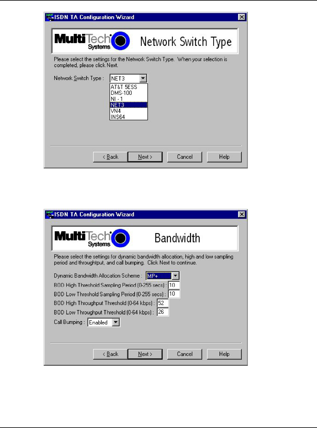
5. The Network Switch Type screen is displayed with Please select the settings for the Network Switch Type.
Select the network switch type you listed in the Before You Start section of this chapter.
6. Please select the settings for dynamic bandwidth allocation, high and low sampling period and
throughput, and call bumping.
Click Next to continue.

Configuration Utility
19
7. The TEI (Terminal Endpoint Identifier) screen is displayed with Please select the settings you would like for
Data TEI and Voice TEI.
The TEI is a unique number assigned to the TA at subscription time. The TEI is used by the telephone central
office (CO) to identify the various TAs connected to the ISDN network. The TEI number can be fixed (range 0 -
63) or dynamic and is assigned automatically at the CO each time the TA connects to the ISDN interface and
powers up.
Click Next when you are finished.
8. The SPID (Service Profile Identifier) North America only, is displayed with Please enter the data SPID, voice
SPID, data directory numbers, and voice directory number of your network.
SPID is only used in North America. A SPID is the ISDN network parameter for local terminal identification

Configuration Utility
20
and tracking. A SPID is assigned by your local ISDN provider when you subscribe, they are in the form of a
string of up to 20 characters. A SPID points to a specific location in the provider’s central office memory where
service and feature parameters are stored.
Click Next when you have entered your SPID information.
9. The Call Control Setup screen is displayed with Please select the settings for call control.
Call Control Setup allows you to set up your terminal adapter and customize how it dials and answers. You can
configure persistent DTR dialing, calling line identification, auto answer data calls, and number of rings. You
can also set the online inactivity timer as well as the dialing method.
Click Next when you are done.

Configuration Utility
21
10. The Data Protocol Setup screen is displayed with Please select the setting you desire for the Data Protocol.
If you would like the TA to detect the data protocol of an incoming data call and automatically change the TA’s
protocol to match the incoming call, click auto protocol detection check box. Click Next to continue.
11. The Stored Numbers screen is displayed with Please enter the numbers you would like to store.
You can store up to ten phone numbers with up to 25 characters per number. Stored number zero is used if
Persistent DTR Dialing is enabled in Call Control Setup screen.

Configuration Utility
22
12. The Port Control Setup 1 screen is displayed with Please select the settings you would like for the DTR detect
time, DCD drop time, DTR, DSR, CTS, and DCD signals.
lick Next when you have finished entering your settings.
13. The Port Control Setup II screen is displayed with Please select the settings you would like for the Default
Parity, Default Bit Rate, number of Data Bits, number of Stop Bits, Flow Control, and synchronous
mode.
Click Next when you are finished.

Configuration Utility
23
14. The POTS Port screen is displayed with Please select the settings for the PORTS port.
When your selections are complete, click Next.
15 The Save Configuration screen is displayed with Please enter the name to store the configuration as in the .ini
file.
You can enter any name up to 35 characters or less in the Store Configuration as: window. Click Next after you
have selected a name.

Configuration Utility
24
16. The Load Configuration screen is displayed with To load the configuration now, click Next.
17. Your ISDN TA is currently being configured.
When the Finish button becomes active, click Finish.
18. The Configured screen is displayed. Click Finish to exit the Configuration Utility.

AT Commands, S-Registers, & Result Codes
25
Chapter 4: ATCommands, S-Registers, and Result Codes
MTA128S T/NT Commands and S-Registers
All references to “TA” in this chapter refer to the MTA1 28ST/NT. This chapter also assumes knowledge of
issuing AT commands. <CR> refers to the carriage return character (typically generated by pressing the
ENTER or RETURN key on the keyboard).
For command execution details see the additional documents on this CD.
AT Commands
The TA’s command buffer can store 80 characters, including spaces and other characters used in
telephone numbers. If you mistype a command string, you can edit it by using the backspace or the delete key,
but only before you press <CR>. As you type a command string, it appears on your monitor screen, letting
you verify your input as you type it. The table below lists the AT commands recognized by the TA.
If your MTA1 28ST/NT is connected to a computer terminal, you can send AT commands to the
MTA1 28ST/NT by entering them on the keyboard. If your MTA1 28ST/NT is connected to a computer, you
can send AT commands to the MTA128ST/NT by typing them in the terminal window of a data
communications program such as HyperTerminal. You can also send some AT commands indirectly by
configuring your data communications program.
To enter AT commands, use the following format: AT <command string> <cr>. The characters AT cause the
MTA128ST/NT to interpret the following string as a command. The command string consists of one or more
commands. The carriage return character, <cr>, sends the command string to the MTA128ST/NT. If you are
entering a command string in your communication program’s terminal window, insert the carriage return
character by pressing the ENTER key on your keyboard. If configuring a communications program, you
typically must insert the carriage return character by adding ^M to the end of the command string.
The MTA128ST/NT has three modes of operation: offline command mode (the default state), online
command mode, and data mode. The MTA1 28ST/NT responds to AT commands only when it is in one of
the command modes. After the MTA1 28ST/NT establishes a connection and goes online in data mode, it
interprets any further characters you enter as data rather than as commands and transmits them to the
remote device.
When the MTA1 28ST is in data mode, you can switch it to online command mode by sending it an escape
sequence. The MTA1 28ST/NT responds to two types of escape sequences:
•
In-band where the escape sequence is part of the data stream.
The in-band escape sequence is +++AT<cr>. To change the in-band escape character (+),
change the value in register S2.
•
Out-of-band where the escape sequence is outside the data stream. The out-of-band escape
sequence is <break >AT<cr>. You can send the break signal in the out-of-band escape sequence
only from software, not by pressing SHIFT+BREAK on your keyboard.
When it detects the escape sequence, the MTA1 28ST/NT enters online command mode where it responds
to commands while maintaining the connection with the remote device.
The MTA1 28ST/NT’s command buffer can store 80 characters, including spaces and other characters
used in telephone numbers. If you mistype a command string, edit it by using the backspace or the delete key but only
before you press ENTER. As you type a command string, it appears on your monitor screen, letting you verify your
input as you type it.
The AT commands recognized by the MTA128ST/NT are listed by function in this chapter first in an abbreviated
list. For an alphabetical list of AT commands, see the AT commands documents on the CD included with this
product.

AT Commands, S-Registers, and Result Codes
26
AT Commands by Function
Command Execution
AT Attention code
A/ Repeat AT Command
Return or Enter Command execution
+++AT<CR> In-band escape code
<BREAK>AT<CR> Out-of-band escape code
General Information Commands
In Display Product Information
Ln List Active Profile Information
!L Display Network Configuration
>MIBn Management Information Block (MIB) Information
Network Configuration Commands
**s User-User Information Element String
%A97=n Dialing Method
>A0=n Type of Coding
!C0=n Network Switch Type
!C6=n Data SPID
*!C6=n Voice SPID
!D0=n V.120 LLC Information Element
!D3=n SAPI-0 Data TEI
*!D3=n SAPI-0 Voice TEI
!DNn Disable Data DN/MSN n
*!DNn Disable Voice DN/MSN n
!ENn Enable Data DN/MSN n
*!ENn Enable Voice DN/MSN n
>MULT=N Multi-point setting
!Nn=s Data DN/MSN n
*!Nn=s Voice DN/MSN n
Serial Port Configuration Commands
&Cn DCD (Data Carrier Detect) Control
&Dn DTR (Data Terminal Ready) Control
$Dn Persistent DTR Dialing
&En Flow Control
&Mn Asynchronous Mode
@P3=n Parity
@P4=n Data Bits
@P6=n Stop Bits
&Rn CTS (Clear To Send) Control
&RFn CTS/RTS Interaction Control
&Sn DSR (Data Set Ready) Control
$SBn Serial Port Speed
%Sn Serial Port Mode
#Xn Send Multiple Xoff Characters
General Configuration Commands
@CONFIG Configuration Menu
En Command Mode Echo
%En Escape Sequence Options
&Fn Load Factory Profile
%Mn Management Mode
Qn Quiet Mode

AT Command, S-Registers, and Result Codes
27
Sr=n Set S-register
Sr? Read S-register
Vn Verbose Result Codes
&Wn Store Active Profile
Xn Connect Messages
Z Reset to Stored Profile
&Zn= Store Telephone Number
!Z=n Rate Adaptation/Data Protocol
Digital (Data) Call Commands A
Answer Digital Call
Dn Dial Digital Number
DSn Dial Stored Number
Hn Hang up Digital Call
!Hn Digital Call Hold-off Time
&Jn Channel Bundling
O Return Online
Analog (POTS) Call Commands
*An Answer Analog Call
*Bn Send Analog Dial Digit
*Dn Dial Analog Number
*Hn Hang up Analog Call
*!Hn Analog Call Hold-off Time
!RXGn POTS Port Receive Gain
!TXGn POTS Port Transmit Gain
S-Registers
S-registers are sections of memory in which values are stored that affect how the TA operates. S-registers
are so-called because each has a name that begins with the character S. Use the Sr=n command to
assign a value to an S-register or use the Sr? command to read the current value of an S-register. S-
registers are stored in non-volatile RAM (NVRAM) by using the &W0 command. ATZ<CR> restores S-
registers to values stored in NVRAM if any were stored using the &W0 command, otherwise they revert to
factory default settings in ROM. Table 4-2 summarizes the available S-registers and their function.
See the additional documents on this CD for more information on each S register.
S-Register Summary
S-Register Function
S0 Rings Until Answer
S1 Ring Count
S2 Escape Character
S3 Carriage Return Character
S4 Line Feed Character
S5 Backspace Character
S7 Wait for Connection (Abort Timer)
S8 Pause Time for Comma
S10 DCD Drop Time
S25 DTR Drop Time
S26 Delay DTR Monitoring After Connect
S27 RS-232 CLEAR Synchronization Sequence
S29 On-line Inactivity Timer Period
S30 On-line Inactivity Timer
S31 Maximum Re-dial Timeout Value
S32 Escape Sequence Timeout

AT Commands, S-Registers, and Result Codes
28
S34 Maximum Escape Sequence Length
S44 POTS Port Ring Frequency
S45 Use Dial Tone From Central Office
S46 Pulse-Dial Recognition
S49 POTS Port Dial Tone Gain
S50 Caller Line ID (CLI)
S51 POTS Port Dial Tone Suppression
S52 Auto-Protocol Detection
S53 Maximum X.75 Buffer Size
S54 Force 56Kbps B-Channel Data Rate
S55 Information Transfer Capability for POTS Port Calls
S56 Calling Party Number Information Element Settings
S57 Called Party Number Information Element Settings
S58 Client-side PPP/ML-PPP Authentication Protocol Negotiation
S59 Dynamic Bandwidth Allocation (DBA) Scheme
S60 Bandwidth-On-Demand
(BOD) High Threshold Sampling Period
S61 Bandwidth-On-Demand (BOD) High Throughput Threshold
S62 Bandwidth-On-Demand (BOD) Low Threshold Sampling Period
S63 Bandwidth-On-Demand (BOD) Low Throughput Threshold
S64 Call Bumping (CB)
S65 POTS Call Bump Forwarding Delay
S66 Country Selections for POTS Ring Signal
S67 Single or Dual Cadence POTS Ring Signal
S68 POTS Ring Signal First Active Duration
S69 POTS Ring Signal First Idle Duration
S70 POTS Ring Signal Second Active Duration
S71 POTS Ring Signal Second Idle Duration
S73 MultiLink Endpoint Discriminator Type
S74 Maximum CLEAR Buffer Size
S80 Persistent DTR Dialing Delay
S81 Link Setup Timeout
S84 Data to Terminal Delay
S85 Data to B-channel Delay
S87 INS64 Analog Call Origination Delay
S154 B-Channel Answer Rate

AT Command, S-Registers, and Result Codes
29
Result Codes
When the MTA128ST/NT receives an AT command from the computer or terminal, it attempts to execute the
command, then sends a status message to the computer or terminal that reports the result of the command.
The MTA1 28ST/NT provides you with several of these response messages, or result codes, which can be
displayed on your monitor or intercepted and used by your communications software. Using the V
command, you can select whether the result codes are terse (numbers) or verbose (words).
The MTA128ST/NT’s result codes are listed below. Note that the speed of an ISDN channel is always
either 56 Kbps or 64 Kbps. Connect messages indicate the speed of the connection between the
MTA1 28ST/NT and your computer or terminal.
TERSE VERBOSE DEFINITION
0 OK TA executed the command without error
1 CONNECT TA established an ISDN connection
2 RING TA detected a ring caused by incoming call
3 NO CARRIER TA did not detect carrier within time allotted by register
S7
4 ERROR Error in the AT command
5 CONNECT 1200 TA connected at 1200 bps
6 NO DIALTONE TA has a poor connection to ISDN network
7 BUSY TA detected a busy signal
8 CONNECT 300 TA connected at 300 bps
9 CONNECT 600 TA connected at 600 bps
10 CONNECT 2400 TA connected at 2400 bps
11 CONNECT 4800 TA connected at 4800 bps
12 CONNECT 9600 TA connected at 9600 bps
14 CONNECT 19200 TA connected at 19200 bps
17 CONNECT 56000 TA connected at 56000 bps
18 CONNECT 57600 TA connected at 57600 bps
19 CONNECT 64000 TA connected at 64000 bps
28 CONNECT 38400 TA connected at 38400 bps
79 PPPC PROTOCOL TA using Point-to-Point protocol
80 HDLC PROTOCOL TA using raw HDLC mode
83 V.120 PROTOCOL TA using V.120 rate adaption protocol
84 X.75 PROTOCOL TA using X.75 rate adaption protocol
87 CLEAR PROTOCOL
TA using CLEAR (transparent) protocol
Using AT Commands to Operate the MTA128ST/NT
You can configure and operate the MTA1 28ST/NT entirely with AT commands if you like. But remember,
you can issue AT commands only from a terminal or from a computer running a communications program in
terminal mode. This section describes how to use AT commands for basic operations, such as calling,
answering a call, and hanging up.
Modes of Operation
The MTA1 28ST/NT has three modes of operation. They are:
•
Offline Command Mode—MTA1 28ST/NT communicates with the terminal or computer and responds to AT
commands. There is no data communications link with a remote device.
•
Data Mode—MTA128ST/NT enters data mode when it makes a successful data communications link
with a remote device. In data mode, the TA can send and receive data, but it does not respond to AT
commands. Instead it treats them as data and transmits them to the remote device.
•
Online Command Mode—MTA128ST/NT responds to AT commands while maintaining a data
communications link; however, transmission of data is suspended. To enter online command mode from
data mode, type the escape sequence +++AT<cr>. To return to data mode from online command
mode, type ATO<cr>.

AT Commands, S-Registers, and Result Codes
30
Making a Call
Before you can place a data call, configure the MTA1 28ST/NT for the local switch type, serial port speed,
and the data type of the ISDN device you want to call. See Chapter 3, Configuration Utilities.
Dialing
To dial a number using AT commands, you must first start a data communications program. In the
program’s terminal mode, type ATDxxxxxxx<cr>, where xxxxxxx is the telephone number you want to
dial, and <CR> is the carriage return character that is sent when you press the ENTER key, such as
ATD7853500<cr>. The dial string can contain up to 80 characters.
To place an ML-PPP call, use an ampersand character (&) to join two telephone numbers, such as
ATD7853500&7853502<cr>. The telephone numbers can be the same or different. Using this method,
two B-channels are activated to transmit data at an aggregate speed of 128 Kbps.
To make it easier to read the dial string, you can use hyphens, spaces or parentheses. These characters are
ignored by the MTA1 28ST/NT. For example, the MTA1 28ST/NT would read the following dial strings the
same way:
ATD17637853500 <cr>
ATD 1-763-785-3500 <cr>
ATD 1 (763) 785-3500 <cr>
Channel Bundling Flag Dialing
The command AT&Jn is used to indicate whether outgoing calls should be made on two B-channels by
default. The command AT&J1&W0<cr>, configures the TA to place a call, dialing on two B-channels by
default. If no second number is given in the dial string, that single number is dialed twice. This
compensates for the interworking issues with Windows Dial-Up Networking. On the other hand, if the
user explicitly indicates two numbers in the dial string, then two numbers are dialed (e.g.,
ATD7853500&785 3502<cr>). The command AT&J0&W0<cr>, disables automatic call bundling. Note
other valid characters joining two telephone numbers include a plus sign (+), and an exclamation mark
(!).
Note: In Windows Dial-Up Networking, if the Use Country Code and Area Code box is checked in the
Properties window for dial-up connection, the bundling modifier (i.e., &, + or!) is removed from the
dialing string when the user attempts to make a connection. The solution is to not check the Use Country
Code and Area Code box or to simply add the bundling dial modifier to the phone number at the time of
connection.
Canceling a Call
To cancel a call before the MTA128ST/NT makes a connection, press any key.
Storing a Telephone Number
To store a telephone number, type &Zn=x in terminal mode, where n is the number of the memory
register in which the number is to be stored, and x is the dial command string that you want to store.
For example, type AT&Z9=763-785-3500 <cr> to store the number 763-785-3500 in memory register 9.
Dialing a Stored Telephone Number
To dial a stored telephone number, type DSn in terminal mode, where n is the location of the number
you wish to dial. For example, type ATDS3 <cr> dials a telephone stored in memory register 3 location.
Displaying a Stored Number
To display a stored telephone number, type &Zn? in terminal mode, where n is the memory register
in which the number is stored. For example, type AT&Z5? <cr> to display the telephone number in
memory register 5. To list all ten telephone numbers stored in memory, type ATL <cr>.
Answering a Call
You can answer incoming calls to the MTA128ST/NT either manually or automatically. When the TA
detects an incoming call, it turns on the RI signal on the V.24 interface and sends a RING result code to
the computer or terminal after each ring. If autoanswer is enabled, the TA automatically answers the call.
You can manually answer the call with the A command. Both methods are described below.

AT Command, S-Registers, and Result Codes
31
Answering Manually
If your communication program is in terminal mode when the RING result code appears on your monitor,
you can manually answer the call by typing ATA <cr>.
Answering Automatically
To cause the MTA128ST/NT to automatically answer a call:
1. Enable autoanswer by setting register S0to the ring on which you want the TAto answer (e.g., in
terminal mode, type S0=4 to make the TA answer on the fourth ring). You also can use either of the
configuration utilities to the turn on autoanswer and set the number of rings.
2. Make sure that the TA is offline.
The TA answers the call after the number of rings specified by S0.To disable autoanswer, use a configuration utility or
the command S0=0.
Note: If the user wants to accept calls while DTR is low, the TA must be configured to ignore DTR. To do this, enter
AT&D0<cr>. With this configuration, the TA can accept calls while DTR is low. If this configuration setting is not
made, the TA rejects incoming calls until DTR is high while calls comes in.
Hanging Up
To hang up a call, escape to online command mode (+++AT<cr>), then enter the H command
(ATH<cr>). The escape sequence and hang up command can be combined into one command string:
+++ATH<cr>.

Troubleshooting
32
Chapter 5: Troubleshoot ing
Troubleshooting the TA
Introduction
This chapter describes basic problems you may run into with your MTA128ST/NT and how to solve them. Your
MTA1 28ST/NT was thoroughly tested at the factory before it was shipped. If you are unable to make a
successful connection, or if you experience data loss during your connection, it is possible that the MTA1
28ST/NT is defective. However, it is more likely that the source of your problem lies elsewhere. Problems
you may encounter include the following:
• None of the LEDs light when the MTA1 28ST/NT is on.
• The MTA1 28ST/NT does not respond to commands.
• The MTA128ST/NT dials but cannot make a connection.
• You can place data calls but not voice calls, or vice versa.
• You cannot place two simultaneous data calls.
• The MTA1 28ST/NT disconnects while online.
• The MTA1 28ST/NT cannot connect when answering.
• File transfer appears slower than it should be.
• Data is being lost.
• There are garbage characters on the monitor.
If you experience problems, please check the following possibilities before calling Tech Support (see
Chapter 7).
Specific Troubleshooting Situations
SITUATION 1: The !Hn and *!Hn commands can be very useful for certain RAS environments that require at
least 1 second to initialize a port after a call has disconnected (such as Citrix and Novell). For example, when
a call disconnects, Citrix and Novell will begin initializing the port that just disconnected. However, it typically
takes more than 1 second and during that time a call may be received by the digital or analog
port. When this happens, Citrix and Novell do not answer the call nor do they finish the initialization
process. To prevent this problem, setting !H5 and/or *!H5 will set the TA to hold of digital and/or analog
calls for 5 seconds after the respective port(s) disconnect(s). This should give enough time for the digital
and/or analog port to be initialized by Citrix or Novell and enter the “waiting for a call” state.
SITUATION 2: The autobauding code cannot differentiate between 7 data bits, no parity, 1 or 2 stop bits
(7N1 or 7N2) and 7 data bits, mark parity, 1 or 2 stop bits (7M1 or 7M2). The TA assumes 7 data bits, mark
parity, 1 stop bit (7M1) and this case covers 7N1, 7N2, 7M1 and 7M2. However, if for some reason the
assumption of 7M1 causes a problem, then there is a workaround. The addition of the %S3 command and
use of $SBn, @P3=n, @P4=n, and @P6=n will help work around this limitation. See the description for the %Sn
command.
SITUATION 3: The autobauding code cannot differentiate between 8 data bits, no parity, 1 or 2 stop bits
(8N1 or 8N2) and 7 data bits, space parity, 1 or 2 stop bits (7S1 or 7S2). The TA assumes 8 data bits, no
parity, 1 stop bit (8N1) and this setting covers 7S1, 7S2, 8N1 and 8N2. However, if for some reason the
assumption of 8N1 causes a problem, then there is a workaround. The addition of the %S3 command and
use of $SBn, @P3=n, @P4=n, and @P6=n will help work around this limitation. See the description for the
%Sn command.
SITUATION 4: The autobauding code does not report the number of stop bits. This may become a problem if
the terminal is expecting a certain number of stop bits. The addition of the %S3 command and use of $SBn,
@P3=n, @P4=n, and @P6=n will help work around this limitation. See the description for the %Sn command.

Troubleshooting
33
Debugging/Logging/Troubleshooting Commands
The AT commands in this section can be used in attempting to troubleshoot or debug a current problem.
Some commands may be enhanced or limited by the debugging/logging/troubleshooting S-registers. For
complete descriptions of the commands and S-registers, see the additional documents on this CD.
Debugging/Logging/Troubleshooting Command Summary AT
Command Function
>Dn Embedded Protocol Analyzer (EPA)
*FSn Reset TA
*Ln Fatal Error Information
>LOG Display Logging Buffer Contents
>Sn Logging Variables
>TIME Display Current Timestamp
*V Various State Information
Debugging/Logging/Troubleshooting S-Registers
The S-registers in this section can be used in attempting to troubleshoot, debug, or even correct a current
problem. Some S-registers modify functionality of various features. Some S-registers modify the
functionality of the debugging/logging/troubleshooting commands described in the additional documents on
the system CD.
Debugging/Logging/Troubleshooting S-Register Summary
S-register Function
S47 Pulse-dial Maximum Break Pulse Period
S48 Pulse-dial Maximum Interdigital Pause
S72 EuroISDN Variant
S90 Local PPP Capabilities
S91 Remote PPP Capabilities
S92 Channel ID Information Element Octet 3 Settings
S93 Blacklisting
S94 Minimum Buffer Space After Trigger
S95 Logging Buffer Functionality
S96 Decode (EPA) Buffer Functionality
S98 ISDN_MSG Size
S99 Startup Options
S100 Flow Control High Threshold
S101 Flow Control Low Threshold
S102 Data to Save for Decoding
None of the LEDs light when the MTA128ST/NTis on
When you turn on the MTA128ST/NT, the LED indicators on the front panel should flash briefly as the TA
runs a self-test. If the LEDs remain off, the TA probably is not receiving power.
• Make sure the MTA128ST/NT’s power switch is on, especially if you normally turn on the TA by
turning on a power strip.
• If the power supply is plugged into a power strip, make sure the power strip is plugged in and its
power switch is on.
• Make sure the power supply module is firmly connected to the MTA128ST/NT and to the wall outlet
or power strip.
• If the power strip is on and the MTA1 28ST/NT is switched on, try moving the TA’s power supply to
another outlet on the power strip.
• Test that the outlet is live by plugging a lamp into it.

Troubleshooting
34
• The MTA1 28ST/NT or power supply may be defective. If you have another Multi-Tech MTA1 28ST/NT, try
swapping MTA128ST/NTs. If the problem goes away, the first MTA128ST/NT or power supply may be
defective. Call Tech Support for assistance.
Caution: Do not under any circumstances replace the power supply module with one designed
for another product, as it may damage the MTA1 28ST/NT and void your warranty.
The MTA128ST/NT does not respond to commands
• Make sure the MTA1 28ST/NT is plugged in and turned on. (See None of the LEDs Light When the
MTA 128S T/NT Is On.)
• Try resetting your MTA128ST/NT by turning it off and on.
• Make sure you are issuing the MTA128ST/NT commands from the data communications software, either
automatically, or manually in terminal mode. (You cannot send commands to the MTA1 28ST/NT from the
DOS prompt.)
• Make sure you are in terminal mode in your data communications program. Then type AT and press
ENTER. If you get an OK response, your connections are good and the problem likely is in your
phonebook entry or session settings.
• If you don’t get an OK, the problem may still be in the communications software. Make sure you have
done whatever is necessary in your software to make a port connection. Not all communications pro-
grams connect automatically to the COM port. Some connect when the software loads and remain
connected until the program ends. Others, like MultiExpress Terminal, can disconnect without ending the
program (make sure the Connect icon looks plugged in). MultiExpress Terminal also allows multiple
terminals to be open, but only one can access the MTA128ST/NT at a time. If MultiExpress Terminal
reports that it cannot make a connection, yet the MTA128ST/NT’s TR indicator is on, click on the Window
menu to see if more than one terminal is open. The MTA128ST/NT’s TR indicator shows that the
software has made a connection with the TA through the COM port.open, but only one can access the
MTA128ST/NT at a time. If MultiExpress Terminal reports that it cannot make a connection, yet the
MTA128ST/NT’s TR indicator is on, click on the Window menu to see if more than one terminal is open.
The MTA128ST/NT’s TR indicator shows that the software has made a connection with the TA through
the COM port.
• Your communications software settings may not match the physical port the MTA128ST/NT is connected
to. The serial cable may be plugged into the wrong connector—check your computer documentation to
make sure. Or you may have selected a COM port in your software other than the one the MTA1 28ST/
compare the settings in your software to the physical connection.
• If the MTA1 28ST/NT is on, the cable is plugged into the correct port, the communications software is
configured correctly, and you still don’t get an OK, the fault may be in the serial cable. Make sure it
is firmly connected at both ends.
• Is this the first time you have used the cable? If so, check the cable description on the packaging to
make sure the cable is correct for your computer.
• Peripheral expansion cards, such as bus mouse and sound cards, may include a serial port preconfig-
ured as COM1 or COM2. The extra serial port, or the card itself, may use the same COM port, memory
address, or interrupt request (IRQ) as your communications port. Be sure to disable any unused ports.
To look for address or IRQ conflicts, select File, Run in Program Manager, type MSD, and press ENTER.
Then select Mouse, COM Ports, and IRQ Status and note the addresses and IRQs that are in use. If you
find an IRQ conflict, note which IRQs are not being used, then change one of the conflicting devices to
use one of the unused IRQs. If you find an address conflict, change the address of one of the conflicting
devices.
To change a port address or IRQ, double-click the Control Panel icon, then the Ports icon. Click on the port you
want to change, click Settings, click Advanced, and select the new port address and/or interrupt. If you
wish to use COM3 or COM4, note that COM3 shares an IRQ with COM1, as does COM4 with COM2, so

Troubleshooting
35
you should change their IRQs to unused ones, if possible.
Right-click on My Computer, select Properties from the menu, click on the Device Manager tab, double-click on
Ports, then double-click on the Communications Port your MTA1 28ST/NT is connected to. In the port’s
Properties sheet, click on the Resources tab to see the port’s Input/Output range and Interrupt Request.
If another device is using the same address range or IRQ, it will appear in the Conflicting Device List.
Uncheck Use Automatic Settings to change the port’s settings so they do not conflict with the other
device, or select the port the conflicting device is on and change it instead. If you need to open your
computer to change switches or jumpers on the conflicting device, refer to the device’s documentation.
• The serial port may be defective. If you have another serial port, install the MTA1 28ST/NT on it, change
the COM port setting in your software, and try again.
• If using serial rates above 115,200 baud, make sure the serial port can handle higher rates. Most
standard serial ports have a maximum serial rate of 115,200. To handle serial rates of 230,400 baud and
460,800 baud, you need a high-speed serial port Even though some terminal emulation programs allow
you to select higher rates, the serial ports cannot always handle those rates.
• The MTA1 28ST/NT may be defective. If you have another Multi-Tech MTA1 28ST/NT, try swapping
MTA1 28ST/NTs. If the problem goes away, the first MTA1 28ST/NT is possibly defective. Call Tech
Support for assistance (see Chapter 7).
The MTA128ST/NT dials but cannot make a connection
There can be several reasons the MTA128ST/NT fails to make a connection. Possibilities include
• Lack of a proper physical connection to the communication line.
• A busy signal.
• Awrong number.
• No terminal adapter at the other end.
• A faulty communications device, computer, or software at the other end.
• Incompatibility between communications devices.
• An improperly configured MTA128ST/NT.
Narrow the list of possibilities by using extended result codes. To enable them, enter ATV1X2 and press
ENTER while in terminal mode or include V1X2 in the MTA128ST/NT’s initialization string (V1X2 is
enabled by default). When you dial again, the MTA128ST/NT reports the call’s progress.
• If the MTA128ST/NT reports NO DIALTONE, check that the ISDN S/T cable is securely connected to
both the TA’s ISDN jack (not the PHONE jack) and the ISDN network terminator or wall jack. If the cable
looks secure, try replacing it. If that doesn’t work, the problem may be in your building’s telephone
installation. Make sure ISDN cables on all devices are wired straight-through (pin 1 to pin 1, pin 2 to pin 2,
etc.) and do not have reversed pairs. The cable must have at least the middle four pins (pins 3, 4, 5, and
6) connected. A reversed pair on the U (phone company) side is not important, but a reversed pair on the
S/T (your) side can create problems if you have more than one device, since multiple devices attached to
the S/T interface must all have the same polarity.
• If the MTA1 28ST/NT reports BUSY, the other number may be busy, in which case you should try again
later.
• If the MTA1 28ST/NT reports NO CARRIER, no connection was made. You might have dialed the correct
number but the other computer or software was turned off or faulty. Check the number and try again, or
try calling another system to make sure your TA is working. Also, check that you accurately configured
the TA with the correct switch type, TEIs, data protocols, and other parameters needed for a successful
call (see Chapter 3).
You can place data calls but not voice calls or vice versa
• You might not have ordered both voice and data service from your ISDN provider. Check your contract or
latest statement of service from your ISDN provider.
• Your ISDN provider may have programmed the switch incorrectly. Call the provider.

Troubleshooting
36
You cannot place two simultaneous data calls
• You may not have ordered an ISDN line configuration that supports two simultaneous calls. Check your
contract or latest statement of service from your ISDN provider. Also, your ISDN provider may have
programmed the switch incorrectly. Call the provider.
• You may have misconfigured your MTA128ST/NT to dial two simultaneous data calls. The command
AT&J1&W0<cr> is used to indicate whether outgoing calls should be made on two B-channels by default.
• You may be using the wrong bundling dial modifier (e.g., ATD7853500&7853502<cr>). The ampersand in
this command string is correct. Other valid characters joining two telephone numbers include a plus sign
(+) and an exclamation mark (!).
Note: In Windows 98/NT/ME, if the Use Country Code and Area Code box is checked in the Properties
window for dial-up connection, the bundling modifier (i.e., &, + or!) is removed from the dialing string
when the user attempts to make a connection. The solution is not to check the Use Country Code and Area
Code box or to simply add the bundling dial modifier to the phone number at the time of connection.
The MTA128ST/NT disconnects while online
• Check for loose connections between the MTA128ST/NT and the computer, the ISDN jack, and AC
power.
• The problem may have originated at the other end of the line. Try again.
• If you were online with a BBS or online service, it may have hung up on you because of lack of activity
on your part or because you exceeded your time limit for the day. Try again.
The MTA128ST/NT cannot connect when answering
• Autoanswer may be disabled. Turn on autoanswer in your data communications program or send the
command ATS0=1 to your MTA128ST/NT in terminal mode.
Note: If the user wishes to accept calls while DTR is low, the MTA1 28ST/NT must be
configured to ignore DTR. This is accomplished by entering AT&D0<cr>. With this configuration,
the MTA128ST/NT is able to accept calls while DTR is low. If this configuration setting is not made,
the TA rejects incoming calls until DTR is high while the calls comes in.
File transfer appears slower than it should be
• If you have a Universal Asynchronous Receiver/Transmitter (UART) that is compromising
data throughputs, we recommend replacing it with a special I/O card.
• If you are running under Windows 3.1 and have a 1 6550AFN UART, replace the Windows serial driver,
COMM.DRV, to take full advantage of the UART’s speed.
• Check the serial port baud rate in your communications software, and make sure it is set as high as
your UART allows.
Data is being lost
• Your UART may not be reliable at serial port speeds over 9600 bps or 19,200 bps. Reset your serial port
speed to a lower rate, or replace your serial port with a faster one.
• Check the serial port baud rate in your communications software, and make sure it is set as high as your
UART allows.
• Make sure the flow control method you selected in software matches the method selected in the
MTA1 28ST/NT.
Garbage characters appear on the monitor
Your computer and the remote computer may be set to different parities. Check with the remote system
and set your communications software to use the same parity as the remote system.
Making a V.120 call, caller gets a NO CARRIER message after dialing the number.
Some switches don’t support ISDN SETUP messages that contain a LLC (low layer compatibility)
element. When these switches receive an LLC in the SETUP, they immediately reject the call and a NO
CARRIER message displays. Disable LLC for V.120 calls by issuing the command AT!D0=0. To enable
LLC again for V.120 calls, issue the command AT!D0=1 (the default setting).

Troubleshooting
37
When using X.75 data protocol to transfer data via the Zmodem, the Zmodem displays Intermittent bad
packet errors and data throughput drops.
This occurs in cases when the X.75 packet size is greater than 1024 bytes and the terminal adapter
sending the file has a fast serial baud rate (e.g., 115200 bps) and the terminal adapter receiving the file
has a slow serial baud rate (e.g., 19200 bps). To reduce or possibly eliminate this, reduce the X.75 packet size
(S53) to a value less than or equal to 102 bytes (e.g., ATS53=512). However, if you set the receiving terminal
adapter’s serial baud rate nearly equal to or greater than the serial baud rate of the sending terminal
adapter, then the packet size can be greater than 1024, and Zmodem transfers the data without bad packet
errors.
The MTA128ST/NT won’t accept V.120 calls from a 3Com Impact IQ terminal adapter. The Impact IQ
displays a connected status, but the MTA128ST/NT does not.
The MTA128ST/NT is looking for a SABME command from the Impact IQ to finish establishing the V.120
connection. However, the Impact IQ won’t send a SABME until it has data to send. Have the Impact IQ
send a character by pressing any key (such as the space bar) on the terminal attached to the Impact IQ. The
MTA128ST/NT responds with a CONNECT message and displays the key you pressed (e.g., a space).
MTA128ST/NT receives garbage characters when connected to a 3Com Impact IQ terminal adapter.
Most likely, the Impact IQ has compression turned on. The compression used by the Impact IQ is
incompatible with the compression used by the MTA1 28ST/NT. Disconnect the data connection and give
the Impact IQ the command AT%CO and then establish the data connection again. The garbage
characters should disappear.
The MTA128ST/NT receives garbage characters after receiving several good characters when connected
to a 3Com Son ix adapter.
Most likely, the Sonix has compression turned on. The compression used by the Sonix is incompatible with
the compression used by the MTA1 28ST/NT. Disconnect the data connection and the give the Sonix the
command AT”HO (that’s a double quote) and then establish the data connection again. The garbage
characters should disappear.
Each time a 3Com Sonix terminal adapter originates a V.120 call, the MTA128ST answers the call as a
V.110 call.
The Sonix sends V.1 10 information in the SETUP message to the network. Since the MTA128ST’s default
is with Auto Protocol Detection enabled (ATS52=1), it looks at SETUP information from the Sonix and
determines erroneously that it is a V.1 10 call. Disable Auto Protocol Detection in the MTA128ST with the
command ATS52=0 and try the connection again.
The MTA128ST/NT won’t connect to an ELSA terminal adapter with the V.120 data protocol.
Most likely, the ELSA terminal adapter has compression turned on. The compression used by the ELSA
terminal adapter is incompatible with compression used by the MTA128ST/NT. Give the ELSA the
command AT%CO to disable compression and try again.
Apple Macintosh Compatibility
The IWay Hopper works with all Macintosh models with a serial port. Some models may require a USB-to-
serial adapter since the MTA1 28ST/NT is a serial RS-232 device. Scripts are provided for Mac OS 8
through Mac OS X. These scripts also work with Mac OS 7.x with the Apple Internet Connection Kit
installed. (OS 8 and 8.1 have the Apple Internet Connection Kit built-in and Mac OS 8.5 through Mac OS X
have Internet connection capabilities built-in.) If you don’t use the Internet connection abilities provided by the
Mac OS, then you will need to create your own initialization string to suit your needs. Generally, these
initialization strings can be based on the Factory Profile command &Fn to set up the desired protocol.

PPP/MLPPP
38
Chapter 6: Point -t o-Point Communications: PPP/MLPPP
Bonding Using the &, I and + Characters
You can use the &, ! and + characters to bond two channels together when performing channel bonding
(available only with the MLPPP protocol).
When you use the &, +, or! characters with the MLPPP protocol, the TA regards the number following that
character as a second phone number. When used with MLPPP, the TA first dials the number given before
the &, +, or! character. After establishing the LCP (Link Control Protocol) and authenticating (if
requested), the TA dials the second number (the number after the &, +, or! character).
This is an alternative method to set up a MultiLink PPP call as opposed to using the &J1 command, which
dials the given number twice rather than dialing two different numbers.
Example: ATD5551000&5553000 dials 5551000 first, sets up the LCP and authenticates, and then dials
5553000 and sets up the LCP and authenticates on the second B-channel (thus setting up an MLPPP
call).
Note: Using these characters with any protocol other than the PPP/MLPPP protocol does not result in the
use of two B-channels at this time.
Making PPP/MLPPP Connections
Making a PPP or MLPPP connection is not as simple as using a terminal emulation program and dialing one
or two phone numbers. Using the PPP data protocol provided by the TA (!Z=9) requires that the TA receives
PPP-formatted data from the terminal. If the TA does not receive PPP-formatted data, the data is discarded by
the TA and never sent to the peer. The TA can receive PPP-formatted data from the peer and send it to the
terminal, but if it is sending the data to a terminal emulation program running on the terminal, the data
appears as garbage.
The PPP data protocol requires PPP data to be sent from the terminal in order for the data to be sent to the
other side. The MultiLink protocol requires the PPP protocol to establish itself on one B-channel before the
second channel is dialed. The LCP can be established only if data is sent by the terminal to the TA.
Negotiation actually occurs between the local terminal and the remote peer. The TA simply views the
negotiation, so it knows how to negotiate on the second B-channel. When the second B-channel connects, the
local terminal is unaware and doesn’t participate in the LCP negotiation. Therefore, the TA must mimic the
negotiation that was witnessed on the first channel.
For example, sending ATDT5551000&5553000 from a terminal emulation program to the TA does NOT
cause the TA to dial two channels and bring up the 128K LED. However, if that dial command was given by
Windows Dial-Up Networking, for example, then there is a chance that the TA dials two channels and
brings up the 128K LED if the user name and password are correct, if the IP address is okay, and if the
peer allows a MultiLink connection. If MultiLink is not allowed, then the TA uses one channel for the PPP
connection. If the user name or password are invalid or incorrect, the connection is terminated. If an IP
address is in conflict, the connection is terminated as well.
Software Applications that can Format PPP Data
Software applications that can format PPP Data for Microsoft-compatible PCs include Windows Dial-Up
Networking (DUN) and WinSock.
Software applications that can format PPP Data for Apple Macintoshes include OT/PPP, MacPPP,
FreePPP, GearBox, and pppd via Internet Connect (Mac OS X).
Dynamic Bandwidth Allocation (DBA)
Dynamic Bandwidth Allocation (DBA) supports the addition and removal of data channels according to the
level of throughput through the TA and according to analog POTS port use.
If throughput is above a given threshold, a second data channel is added to facilitate higher throughput.
If throughput drops below a given threshold, the second channel is removed to save the cost of having the
second B-channel active but not fully used.

PPP/MLPPP
MTA128ST/NT 39
If an outgoing analog call is desired or there is an incoming analog call, a data channel can be bumped
(removed) to allow analog POTS port use.
Bandwidth-on-Demand (BOD) checks the data throughput to determine whether a channel should be
added or removed.
Call Bumping (CB) determines whether a channel needs to be added again (analog call disconnected) or
removed (incoming or outgoing analog call desired) due to activity on the analog POTS port.
To activate Bandwidth-on-Demand or Call Bumping, enable Dynamic Bandwidth Allocation in S-register S59.
The 128 LED flashes if DBA is active and only one data channel is connected. The 128 LED stops flashing
and remains on after the second B-channel is successfully added. If the second channel is disconnected
due to low throughput or a call-bump, the 128 LED flashes again to indicate that DBA is still active.
If the TA attempts to add a B-channel, but the host is busy or not answering, the TA starts a timer (time is set
in S-register S31). However, if the analog device goes off-hook or an analog call is received, the timer is
stopped and reset. After the analog call finishes, the TA again attempts to add the B-channel. Taking the
analog device off-hook and placing it on-hook again interrupts the timer, thus allowing control over the
amount of time it takes before attempting to add the second channel (rather than waiting for timeout values
specified by S31).
DBA Data Protocols
MLPPP is the only data protocol that currently supports DBA. To start DBA, set &J1 or give two numbers
to be dialed. Otherwise, the TA will not negotiate the MultiLink Protocol (MP) option. If the MultiLink
Protocol option is not negotiated, Dynamic Bandwidth Allocation is not possible.
DBA Features:
Bandwidth-on-Demand (BOD)—S60, S61, S62, and S63
• Bandwidth-on-Demand (BOD) is not available to the host TA if Dynamic Bandwidth Allocation is disabled
(S59=0) or if the Dynamic Bandwidth Allocation scheme is PPP (S59=2).
• Setting S60=0 disables the BOD feature completely (meaning S61, S62, and S63 are disabled as well).
• To calculate High Throughput Average (in Kbps):
– Divide the total number of bits received from the PC (not including start, stop, or parity bits) during
the High Threshold Sampling Period (S60) by the High Threshold Sampling Period (S60) value (in
Kbps).
Total bits received S60 = High Throughput Average
– Or, divide the total number of bits transmitted to the PC (don’t include start, stop, or parity bits) during
the High Threshold Sampling Period (S60) by the High Threshold Sampling Period (S60) value (in
Kbps).
Total bits transmitted S60 = High Throughput Average
If the average (transmitted or received) exceeds the High Threshold (S61) and only one data channel is
active and the second B-channel is not already in use, the TA attempts to add a second data channel.
• To calculate Low Throughput Average (in Kbps):
– Divide total number of bits received from the PC (not including start, stop, or parity bits) during the
Low Threshold Sampling Period (S62) by the Low Threshold Sampling Period (S62) value (in Kbps).
Total bits received S62 = Low Throughput Average
– Or, divide total number of bits transmitted to the PC (not including start, stop, or parity bits) during the
Low Threshold Sampling Period (S62) by the Low Threshold Sampling Period (S62) value (in Kbps).
Total bits transmitted S62 = Low Throughput Average
If either average (transmitted or received) equals or is less than the Low Threshold (S63) and there are
two active data channels, the TA disconnects the second data channel.
• Ideally, the second channel should be added quickly (short High Threshold Sampling Period [S60] with a
relatively small High Throughput Threshold [S61]). Also, the second channel should not be disconnected

PPP/MLPPP
40
for a relatively long period of time (long Low Threshold Sampling Period [S62] with a small Low
Throughput Threshold [S63]).
• If data transmits or is received in bursts and the TA adds and removes a channel too quickly,
increase the High Threshold Sampling Period (S60) and the Low Threshold Sampling Period (S62) and
– decrease the Low Throughput Threshold (S63).
Call Bumping (S-register S64)
• Call Bumping is not available to the host TA if Dynamic Bandwidth Allocation is disabled (S59=0) or if
the Dynamic Bandwidth Allocation scheme is PPP (S59=2).
• If the analog device goes off-hook or there is an indication of an incoming analog call and both B-
channels are in use by a data call, the TA drops the second B-channel and rings the analog device.
• If the analog device goes on-hook or the peer disconnects the analog call, the TA adds the second B-channel
again according to whether BOD is enabled or disabled (S60). If BOD is disabled (S60=0), the second
channel is added immediately. If BOD is enabled (S60 is non-zero), the second channel is added after the
High Threshold Sampling Period (S60) and High Throughput Threshold (S61) determine whether
throughput is high enough to allow adding the second channel.

Warranty, Service, and Tech Support
41
Chapter 7: Warranty, Service, and Tech Support
Multi-Tech Systems, Inc. Warranty & Repairs Policies
Warranty
Multi-Tech Systems, Inc., (hereafter “MTS”) warrants that its products will be free from defects in material or
workmanship for a period of two, five, or ten years (depending on model) from date of purchase, or if proof
of purchase is not provided, two, five, or ten years (depending on model) from date of shipment.
MTS MAKES NO OTHER WARRANTY, EXPRESS OR IMPLIED, AND ALL IMPLIED WARRANTIES OF
MERCHANTABILITY AND FITNESS FOR A PARTICULAR PURPOSE ARE HEREBY DISCLAIMED.
This warranty does not apply to any products which have been damaged by lightning storms, water, or power
surges or which have been neglected, altered, abused, used for a purpose other than the one for which they
were manufactured, repaired by Customer or any party without MTS’s written authorization, or used in any
manner inconsistent with MTS’s instructions.
MTS’s entire obligation under this warranty shall be limited (at MTS’s option) to repair or replacement of any
products which prove to be defective within the warranty period or, at MTS’s option, issuance of a refund of
the purchase price. Defective products must be returned by Customer to MTS’s factory – transportation
prepaid.
MTS WILL NOT BE LIABLE FOR CONSEQUENTIAL DAMAGES, AND UNDER NO CIRCUMSTANCES
WILL ITS LIABILITY EXCEED THE PRICE FOR DEFECTIVE PRODUCTS.
Repair Procedures for U.S. and Canadian Customers
In the event that service is required, products may be shipped, freight prepaid, to our Mounds View,
Minnesota factory:
Multi-Tech Systems, Inc.
2205 Woodale Drive
Mounds View, MN 55112
Attn: Repairs, Serial #_____________
A Returned Materials Authorization (RMA) is not required. Return shipping charges (surface) will be paid
by MTS in U.S. and Canada.
Please include, inside the shipping box, a description of the problem, a return shipping address (must
have street address, not P.O. Box), and your telephone number. If the product is out of warranty, a payment in
advance is required. Acceptable means of payment include credit card, wire transfer or a check in
U.S.dollars drawn on a U.S. bank.
For out of warranty repair charges, go to COMPANY/Policies/warranty/
Extended two-year overnight replacement service agreements are available for selected products. Please call
MTS customer service at (888) 288-5470, or visit our web site at
/PARTNER/Programs/overnight replacement/ for details on rates and coverages.
Please direct your questions regarding technical matters, product configuration, verification that the product
is defective, etc., to our Technical Support department at (800) 972-2439 or email
support@multitech.com. Please direct your questions regarding repair expediting, receiving, shipping,
billing, etc., to our Repair Accounting department at (800) 328-9717 or (763) 717-5631, or email
mtsrepair@multitech.com.
Repairs for damages caused by lightning storms, water, power surges, incorrect installation, physical
abuse, or user-caused damages are billed on a time-plus-materials basis.

Warranty, Service, and Tech Support
42
Repair Procedures for International Customers (Outside U.S.A. and Canada)
Your original point-of-purchase Reseller may offer the quickest and most economical repair option for
your Multi-Tech product. You may also contact any Multi-Tech sales office for information about the
nearest distributor or other repair service for your Multi-Tech product. The Multi-Tech sales office
directory is available at http://www.multitech.com/partners/channels/offices/
In the event that factory service is required, products may be shipped, freight prepaid to our Mounds View,
Minnesota factory. Recommended international shipment methods are via Federal Express, UPS or DHL
courier services, or by airmail parcel post; shipments made by any other method will be refused. Please
include, inside the shipping box, a description of the problem, a return shipping address (must have
street address, not P.O. Box), and your telephone number. If the product is out of warranty, a payment
in advance is required. Acceptable means of payment include credit card, wire transfer, or a check
in U.S. dollars drawn on a U.S. bank. Repaired units shall be shipped freight collect, unless other
arrangements are made in advance.
Please direct your questions regarding technical matters, product configuration, verification that the
product is defective, etc., to our Technical Support department nearest you or email
support@multitech.com. When calling the U.S., please direct your questions regarding repair expediting,
receiving, shipping, billing, etc., to our Repair Accounting department at (763) 717-5631 in the U.S.A., or
email mtsrepair@multitech.com.
Repairs for damages caused by lightning storms, water, power surges, incorrect installation, physical abuse,
or user-caused damages are billed on a time-plus-materials basis.
Repair Procedures for International Distributors
International Distributors should contact their MTS International sales representative for information about the
repair of Multi-Tech product(s).
Please direct your questions regarding technical matters, product configuration, verification that the
product is defective, etc., to our International Technical Support department (763) 717-5863. When calling the
U.S., please direct your questions regarding repair expediting, receiving, shipping, billing, etc., to our Repair
Accounting department at (763) 717-5631 in the U.S.A., or email mtsrepair@multitech.com.
Repairs for damages caused by lightning storms, water, power surges, incorrect installation, physical
abuse, or user-caused damages are billed on a time-plus-materials basis.
Replacement Parts
SupplyNet, Inc., can supply you with replacement power supplies, cables and connectors for selected
Multi-Tech products. You can place an order with SupplyNet via mail, phone, fax or the Internet at the
following addresses:
Mail: SupplyNet, Inc.
614 Corporate Way
Valley Cottage, NY 10989
Phone: 800 826-0279

Appendice
s
MTA128ST/NT 43
AppendixA:Configuration Profiles
Quick Setup Factory Profiles
For quick setup, the MTA1 28ST/NT includes six Quick Setup Factory Profiles, each of which is configured for a
specific type of port operation. You can load a Quick Setup Factory Profile into active memory by using the
command &Fn, in which n is the number of the profile you wish to load. If you wish, you can then customize the
profile and store it, using the &Wcommand, so that it loads automatically when the MTA1 28ST/NT is turned
on or reset. These profiles are stored in permanent memory and are not user-configurable as such.
MTA1 28ST
&F0 Profile 0—Modem-like operation (default)
&F1 Profile 1—V. 110 async operation
&F2 Profile 2—V.120 async operation
&F3 Profile 3—X.75 async operation
&F4 Profile 4—ML-PPP async operation
&F5 Profile 5—SoftBonding Asynchronous Operation
&F6 Profile 6—HDLC Asynchronous Operation
&F7 Profile 7—CLEAR operation
MTA1 28NT
&F0 Profile 0–Modem-Like Asynchronous Operation
&F1 Profile 1–V.120 Asynchronous Operation
&F2 Profile 2–X.75 Asynchronous Operation
&F3 Profile 3–PPP Asynchronous Operation
&F4 Profile 4–SoftBonding Asynchronous Operation
&F5 Profile5–HDLC Asynchronous Operation
&F6 Profile 6–CLEAR Asynchronous Operation
Quick Setup Example
The following procedure assumes that you want to load, modify, and store Quick Setup Factory Profile 2 as
your default configuration.
1. Select the profile closest to the requirements of your application, in this case— Quick Setup Factory
Profile 2.
2. In terminal mode, type AT&F2 and press ENTER. Quick Setup Profile 2 loads into the MTA128ST/NT’s
active memory.
3. Enter any additional AT commands that you need to customize the selected profile to your application
(see Chapter 4, AT Commands, S-Registers, and Result Codes).
4. Type AT&W0 and press ENTER to save your customized port configuration.
5. Your customized profile now loads automatically whenever the MTA128ST/NT is turned on or reset.

44
Appendices
Appendix B: Ordering Your ISDN Li ne
There are two ways to specify your ISDN line configuration to your service provider. One is by using ISDN
"ordering codes" in which the user, the Local Exchange Carrier (LEC) or Internet Service Provider (ISP)
are using common nomenclature to describe elements of service. The other way of ordering service is to
use a “building block approach”; where the naming conventions are non-standardized, and the user and
provider must establish a set of provisioning options.
Loop Qualification
The first step in ordering (“provisioning”) an ISDN BRI line is to contact your LEC and verify ISDN BRI
loop availability in your location. There is a distance limitation of approximately 2 miles (1800Kf) from the
BRI loop. Each request for BRI is handled on a case-by-case basis. Once qualified, the LEC requires
information on the type of equipment and protocol used. Most ISDN BRI is configured as “voice and data” (due
to the fact that the LEC network is primarily analog, and ISDN digital technology converts the digital signal into
analog, transports it over their analog lines, and then re-converts it into digital data at the other end).
As a general procedure when ordering an ISDN BRI (2B+D) line:
1. Plan ahead; the BRI line order may take four weeks or more to get provisioned.
2. Contact your LEC representative early in the process toensure ISDN BRI loop availability for your
location.
3. Provide the LEC rep. with your correct address for the BRI service.
4. Provide the LEC rep. with the type of equipment (e.g., “Multi-Tech MTA128TA External ISDN
Terminal Adapter”) and the protocol specifications that it supports. Use the “ISDN BRI
(2B+D) Line Ordering Checklist” provided later in this document for the protocol
specifications.
5. Provide the LEC rep. with the type of jack required by the MTA128NT (i.e., “RJ45 male 2-wire U
Basic Rate Interface”).
6. Wait for notification of installation from the LEC; ask the LEC rep what type of switch is used
(AT&T 5ESS and NT DMS-100 are most prevalent).
7. Ensure availability of an “auxiliary” analog line (if you plan on using the MTA1 28NT’s “AUX”
RJ1 1 analog connector for a standard telephone connection). Make sure you have a 115
VAC (60 Hz) power outlet near your computer for the MTA1 28NT’s two-prong outlet-mounted
power transformer.
8. Record all of the information provided by your LEC.
Bearer Service
The options of Circuit Switch Voice Bearer (CSV) and Circuit Switch Data Bearer (CSD) are broad
categories of Bearer Services that the phone companies can provide. Different bearer services
provide different types of guarantees about the reliability and synchronization of the data. There are
currently ten different bearer services for circuit-mode, and three services for packet mode.
These bearer services are defined in terms of a number of attributes, which include mode (circuit or
packet), structure (bit-stream or octet-stream), transfer rate (e.g. 64Kbps), transfer capability (basically,
the content, for instance speech, 7Khz audio, video, or unrestricted), and several other attributes that
specify protocols to use and other things.
The attributes of the bearer service are encoded into a Bearer Code, or BC, that is sent everytime a
new connection is being set up. In theory, this allows the switches to dynamically choose from a
variety of different switching paths techniques depending on requirements. In practice, the
SPID is used to determine what services are needed for switching, as this greatly simplifies things for
the telephone companies. The Bearer Code will not be completely ignored, however there are
certain bearer services that will be unavailable on your B-channels, based on how they are
configured. It is important to note that the Bearer Code is sent to the switch every time a connection
is established. However, the SPID is only sent to the switch when you physically attach your

45
Appendices
equipment to your phone line. At this time the switch gives your device a Terminal Equipment
Identifier (TEI) which is used from then on to identify all connection requests from that piece of
equipment. This allows the switch to look at the TEI and Bearer Code, determine the SPID, and see if
the Bearer Code and the SPID match up.
Using ISDN Ordering Codes (IOCs)
An organization called ISDN Solutions Group, made up of ISDN service providers and
equipment vendors, was formed to simplify the often complex task of ordering an ISDN line. This
method, supported by most (but not all) service providers, uses ISDN ordering codes to define the
ISDN line configuration. Your ISDN TA has been tested to operate with the following ordering codes:
B1, Capability C, Capability R, I2, J2, J3, Capability S, and M5, as described in the following sections.
B1 (previously 'Generic Data B')
This ISDN line ordering code supports:
• 1 B Service,
• Data only on 1 B channel, and
• One directory number.
Capability C (previously 'Generic Data C')
This ISDN line ordering code supports:
• 1 B Service,
• Alternate voice and data on one B channel, and
• One directory number.
Capability R (previously 'Generic Data I')
This ISDN ordering code supports:
• 2B Service,
• Data only on each B channel, and
• Two directory numbers.
Applications for Capability R include:
• 115.2K or 128K bps data only (no voice capability, and
• Generic 115.2K/1 28K bps data transfer applications (including remote access and LAN/WAN
connectivity and telecommuting).
I2 (previously 'Generic Data I-1DN')
This ISDN ordering code supports:
• 2B Service,
• Data only on each B channel, and
• One directory number.
I2 is not available on the Northern Telecom switch. Two directory numbers are required for 2B operation; in
this case use J2.
J2 (previously 'Generic Data J')
This ISDN ordering code supports:
• 2B Service,
• alternate voice and data on one B channel, data only on other B channel, and
• Two directory numbers.

46
Appendices
J3 (previously 'Generic Data J-1DN')
This ISDN ordering code supports:
• 2B Service,
• alternate voice and data on one B, data only on other B channel, and
• One directory number.
J3 is not available on the Northern Telecom switch. Since two directory numbers are required for 2B
operation, use J2.
Capability S (previously 'Generic Data M')
This ISDN ordering code is the recommended IOC since it supports the most features for voice and data
applications. However, ISDN tariffs in some areas may warrant ordering codes with fewer features (e.g.,
where there is an additional monthly charge for having voice service on both B channels). If yours is a
data only application, you may find Capability R more cost-effective.
Capability S supports:
• 2B Service,
• alternating voice/data on each B channel, and
• Two directory numbers.
Applications for Capability S include:
• 115.2K or 128K bps data,
• 56K/64K bps data with voice or modem support, and
• Generic 1 15.2K/1 28K bps data transfer applications (including remote access and LAN/WAN
connectivity and telecommuting).
M5 (previously 'Generic Data M-1DN')
This ISDN ordering code supports:
• 2B Service,
• alternate voice/data on each B channel, and
• One directory number.
M5 is not available for services provided with Northern Telecom or AT&T switches. Since two directory
numbers are required for 2B operation, use Capability S.

47
Appendices
Ordering ISDN Without IOCs
This section guides you and your telephone company in specifying and obtaining ISDN service when
IOCs are not used. To support most ISDN TA features, your telephone service must meet certain
requirements. These requirements are described in the following sections. Some features may be added or
deleted, depending on your actual data service needs and availability in your area. Before ordering, talk to
your telephone company about which of the services listed on the following pages are provided in your area.
The following form was created for you to complete and fax to your telephone company to request the
proper ISDN line for use with your ISDN TA module.
Name: ____________________________________________________
Address:
City: ________________________________ State:________________ ZIP Code:
Daytime Telephone Number: ______________
1. Request an ISDN BRI (Basic Rate Interface) line with:
• U-Interface Reference Point, and
• 2B1Q Line Coding.
2. Choose one of the following:
___ 2B+D Service (supports up to 128K bps), or
___ 1 B+D Service (supports up to 64K bps).
3. Indicate the ISDN Switch Type and Software Protocol you will be using:
___ AT&T 5ESS, with:
___ Custom,
___ 5E6 and later software, or
___ NI1 (National ISDN-1).
___ Northern Telecom DMS-100, with:
___ BCS-32 and later software (Pvc1), or
___ National ISDN-1 (Pvc2).
___ Siemens EWSD with National ISDN-1
4. Request that the ISDN line you are ordering allocates one dynamic TEI (Terminal Endpoint Identifier)
per phone number.
5. Order specific services for your particular ISDN Switch:
5a. AT&T 5ESS: request a line with:
Feature: Value
B1 Service: DMD (On Demand)
B2 Service: DMD (only if 2B+D ordered)
Data Line Class: PM (Point-to-MultiPoint)
Maximum B Channels: 2 (if 2B+D) or 1 (if 1 B+D)
Circuit Switched Voice (CSV) Bearer Channels: Any
CSV Calls: 1 (recommended for test purposes)
Number of Circuit Switched Data (CSD) Bearer Channels: Any
Number of CSD Calls: 2 (if 2B+D ordered), or 1 (if 1 B+D ordered)
Terminal Type: Type A Turn these features OFF:
Packet Mode Data
MultiLine Hunt
Multiple Call Appearances

48
Appendices
EKTS (Electronic Key Telephone Sets)
Shared Directory Numbers
Accept Special Type of Number
Intercom Groups
Modem Pools (Network Resource Selector)
Message Waiting
Hunting
I nterLATA Competition
5b. Northern Telecom DMS-100: request a point-to-multipoint line with:
Line Type: Basic Rate, Functional
Electronic Key Telephone Sets (EKTS): No
Call Appearance Handling (CACH): No
Non-Initializing Terminal: No
Circuit Switched Service: Yes
Packet Switched Service: No
TEI: Dynamic
Bearer Service: Circuit Switched Voice and Data Permitted on Any B Channel (Packet Mode Data not
permitted)
6.____________________________________________________ Select a long distance carrier; note here:
____________________________________________________
7.
Contact the selected long distance carrier and request Circuit-Switched 64K bps Clear Channel Access
(if available).
8. Request that the telephone company provide ISDN TA configuring information (record here):
• ISDN Switch Type: ____________
• ISDN Switch Protocol Version: __
• ISDN Phone Number 1: ___________
• ISDN Phone Number 2: _______ (if 2B+D ordered)
• ISDN Line Type: _____________(point-to-point or multipoint)
• If MultiPoint, SPID Number 1: _______ (with prefix and suffix)
• If MultiPoint, SPID Number 2: ________ (with prefix and suffix)
9. If you will be using standard 5ESS or DMS-1 00, your protocol selection is complete. Fax the
information in steps 1-8 to your phone company. If you will be using 5ESS "Custom" or DMS-1 00 "Pvc1"
protocol support, continue with step 10a (5ESS Custom) or step 10b ( DMS-100 Pvc1).
10a. 5ESS Custom Line Additional Parameters
The AT&T 5ESS central office telephone switch supports a proprietary ISDN D-channel call control protocol
called "Custom" which is based on CCITT recommendations. The ISDN TA configured for switch type AT&T
5ESS will work with lines providing this protocol on 5ESS switches with software version 5E6 or later.
The ISDN TA supports the following configurations on 5ESS Custom lines:
• Point-to-Point with one phone number (recommended configuration with no POTS interface)
• Multipoint with one phone number
• Multipoint with two phone numbers (recommended configuration with POTS interface)
The requirements for the 5ESS line are shown below:
B1 Service: DMD (On-demand)
B2 Service: DMD (On-demand)
Data Class Line: PM (Point-to-MultiPoint) Max. B
Channels: 2

49
Appendices
Number of CSV Calls: 2
CSV Bearer Channels: Any
Number of CSD Calls: 2
Circuit Switched: Any
Terminal Type Bearer Channels: Type A
Multipoint lines require the phone company to create a SPID for each phone number on the line. With the exception of
the ability to spread two calls across two phone numbers, multipoint lines offer no special features, and may create
complications. However, if you use a multipoint line, the parameters are similar to the point-to-point lines, except
for the SPIDs.
The 5ESS switch can provide a variety of supplementary features which the ISDN TA may not support. Enabling
these features may have undesirable consequences.
Features to avoid are:
• Packet mode data
• Multiline Hunt Groups
• EKTS (Electronic Key Telephone Set)
• Shared directory numbers
• Intercom groups
• Modem Pools (Network resource selector)
• Message waiting
• Hunting
• Inter LATA competition
• Accept special type of number
10b. DMS-100 Pvc1 Line Additional Parameters
The Northern Telecom DMS-100 telephone switch supports a proprietary ISDN D-channel call control protocol
called Protocol Version 1 ("Pvc1") which is based on CCITT recommendations. The ISDN TA configured for switch
type DMS-100 will work with lines providing this protocol on DMS-100 switches with software version BCS-32 or later.
The ISDN TA supports the following configurations on DMS-100 Custom lines:
• Multipoint with one phone number (for 1 B+D service)
• Multipoint with two phone numbers (for 2B+D service)
The requirements for the DMS-100 multipoint line are defined in Local Interface Requirements, Local Service
Requirements, and below. Fax this information to your local phone company.
The line should have two service profiles with the parameters below, to support BONDING and the POTS port, if
installed.
Line Type: Basic rate, functional EKTS: No
CACH: No
Initializing terminal: Yes
Bearer services: Circuit-switched voice & data permitted (Packet mode data not permitted) Circuit-switched
service: Yes
Packet-switched service: No Protocol
version: Functional Pvc1 TEI: Dynamic

50
Appendices
AppendixC: FCCand Canadian Regulation
FCC
1. This equipment complies with Part 68 of the Federal Communications Commission (FCC) rules. On the
outside surface of this equipment is a label that contains, among other information, the FCC registration
number and ringer equivalence number (REN). If requested, this information must be provided to the
telephone company.
2. As indicated below, the suitable jack (Universal Service Order Code connecting arrangement) for this equipment is
shown. If applicable, the facility interface codes (FIC) and service order codes (SOC) are shown.
An FCC-compliant telephone cord and modular plug is provided with this equipment. This equipment is
designed to be connected to the telephone network or premises wiring using a compatible modular jack which is
Part 68 compliant. See installation instructions for details.
3. The ringer equivalence number (REN) is used to determine the quantity of devices which may be connected to
the telephone line. Excessive REN’s on the telephone line may result in the devices not ringing in response to an
incoming call. In most, but not all areas, the sum of the REN’s should not exceed five (5.0). To be certain of the
number of devices that may be connected to the line, as determined by the total REN’s, contact the telephone
company to determine the maximum REN for the calling area.
4. If this equipment causes harm to the telephone network, the telephone company will notify you in advance that
temporary discontinuance of service may be required. But if advance notice isn’t practical, the telephone
company will notify the customer as soon as possible. Also, you will be advised of your right to file a
complaint with the FCC if you believe it is necessary.
5. The telephone company may make changes in its facilities, equipment, operations, or procedures that could
affect the operation of the equipment. If this happens, the telephone company will provide advance notice in
order for you to make necessary modifications in order to maintain uninterrupted service.
6. If trouble is experienced with this equipment (the model of which is indicated below) please contact Multi-Tech
Systems, Inc. at the address shown below for details of how to have repairs made. If the equipment is causing
harm to the telephone network, the telephone company may request you remove the equipment from the
network until the problem is resolved.
7. No repairs are to be made by you. Repairs are to be made only by Multi-Tech Systems or its licensees.
Unauthorized repairs void registration and warranty.
8. This equipment cannot be used on public coin service provided by the telephone company. Connection to
Party Line Service is subject to state tariffs. (Contact the state public utility commission, public service
commission or corporation commission for information.)
9. If so required, this equipment is hearing-aid compatible.
Manufacturer: Multi-Tech Systems, Inc.
Model Number: MTA128NT
FCC Registration #: AU7USA-24353-DD-N
Ringer Equivalence: Modular Jack (USOC) RJ45/RJ1 1
Service Center in USA: Multi-Tech Systems Inc.
2205 Woodale Drive Mounds
View, MN 55112 Voice (612) 785-
3500/ FAX (612) 785-9874

Appendices
51
Canadian Limitations Notice
Notice: The ringer equivalence number (REN) assigned to each terminal device provides an indication of
the
maximum number of terminals allowed to be connected to a telephone interface. The termination of a
interface may consist of any combination of devices subject only to the requirement that the sum of the
ringer equivalence numbers of all the devices does not exceed 5.
Notice: The Industry Canada label identifies certificated equipment. This certification means that the
equipment meets certain telecommunications network protective, operational and safety requirements. The
Industry Canada does not guarantee the equipment will operate to the user’s satisfaction.
Before installing this equipment, users should ensure that it is permissible to be connected to the facilities of
the local telecommunications company. The equipment must also be installed using an acceptable method
of connection. The customer should be aware that compliance with the above conditions may not prevent
degradation of service in some situations.
Repairs to certified equipment should be made by an authorized Canadian maintenance facility
designated
by the supplier. Any repairs or alterations made by the user to this equipment, or equipment malfunctions, may
give the telecommunications company cause to request the user to disconnect the equipment. Users
should ensure for their own protection that the electrical ground connections of the power utility, telephone
lines and internal metallic water pipe system, if present, are connected together. This precaution may be
particularly important in rural areas.
Caution: Users should not attempt to make such connections themselves, but should contact the
appropriate electric inspection authority, or electrician, as appropriate.
The CE mark is affixed to this product to confirm compliance with the following European Community
Directives:
Council Directive 89/336/EEC of 3 May 1989 on the approximation of the laws of Member States relating to
electromagnetic compatibility;
and
Council Directive 73/23/EEC of 19 February 1973 on the harmonization of the laws of Member States
relating to electrical equipment designed for use within certain voltage limits;
and
Council Directive 98/1 3/EC of 12 March 1998 on the approximation of the laws of the Member States
concerning telecommunications terminal and satellite earth station equipment.

Appendices
52
AppendixD: Configuration Methods
Firmware-based Configuration Utility
1. If you are using another operating system, turn on your computer and start your data
communications program.
2. The TR (Terminal Ready) LED lights to indicate that your computer is ready to communicate with the
TA.
Type AT in the communications program’s terminal window and press ENTER. The TA should respond with
OK.
If it doesn’t, go to Chapter 5 for troubleshooting help.
3. To view your current configuration, type AT!L in the terminal window. Switch Type and Data Protocol
information appear. The fields for SPIDs (Service Provider Identification) and for Voice and Data
Directory Numbers will be empty. Your TA ships with Auto-TEI (terminal endpoint identifier) as its default.
Refer to before you start in Chapter 3 for your network, call control configuration, and comport settings.
4. To change one or more settings, type AT@CONFIG, press ENTER, and follow the ConfigMenu
directions.
5. Type AT&W and press ENTER to store your settings.
The following is a description of the menus.
Network Configuration Menu. Select this menu to configure network parameters such as the switch type,
data and voice TEIs, and datea nd voice MSNs. When you finish, select Save Hetwork Configuration to save
your work.
Call Control Configuration Menu. Select this menu to change how the MTA128ST/NT originates and
answers calls. Options include Auto Answer, Rings to Answer, Dialing Method, and Persistent DTR Dialing.
Data Protocols Menu. Select this menu to change the rate adaption protocol used by the MTA 128ST/NT.
Stored Numbers Menu. Select this menu to store up to ten phone numbers with a maximum of 25 characters
each. Stored number 0 is the phone number that is dialed if you enable persistent DTR dialing.
Port Control Configuration Menu. Select this menu to configure the MTA128ST/NT’s serial port, including
how the MTA 128S T/NT responds to control signals on the RS232 interface.
POTS Port Configuration Menu. Select this menu to configure the MTA128S T/NT’s POTS port which
includes the ring type, frequency, and pattern.
Help Menu. Select this menu for help on navigating through the MTA128ST/NTmenu system.
Configuration via AT Commands
You can configure the MTA128ST/NT by using AT commands, just as you would configure an analog modem.
Use this method if you prefer to work with AT commands or if you have a special requirement not
addressed by either of the configuration utilities.
Using AT Commands to Configure the MTA128ST/NT
1. Connect a VT1 00/ANSI-compatible terminal, or a computer that has a communications program that has
VT100/ANSI terminal emulation, to the MTA128ST/NT’s serial port.
2. Turn on the MTA128ST/NT. The MTA128ST/NT automatically detects whether an ASCII or ANSI
terminal is in use and adjusts accordingly.
3. Start a data communication program and select the COM port where the MTA1 28ST/NT is connected.
4. Referring to your Before Your Start notes, enter the desired AT commands in the terminal window of the
data communications program.
5. When you finish making changes, use the &Wcommand to save your new configuration, and to select it to
automatically load when the MTA128ST/NT is turned on.
6. Quit the data communications program.
For more information on AT commands, see the MTA128ST and MTA128NT AT Commands documents

Glossary
MTA128ST/NT 53
Glossary
Symbol
2B1Q (2 bits, 1 quarternary)—A line code at layer
one for the BRI U interface. Two bits of data (2B) are
mapped into one of four line values (1Q, or
1quarternary). This coding scheme
allows a single copper pair to carry 160 Kbps of
information bidirectionally and simultaneously at a
distance of up to three miles.
A
ACK (acknowledgement code)—A communications
code sent from a receiving modem to a transmitting
modem to indicate that it is ready to accept data. It is
also used to acknowledge the error-free receipt of
transmitted data. Contrast with NAK.
address—A numbered location inside a computer.
The computer uses addresses to access resources
such as video cards, serial ports, memory, etc.
analog signal—A waveform that has amplitude,
frequency, and phase, which takes on a range of
values between its maximum and minimum points.
analog transmission—A type of telecommunications
that uses an analog signal as a carrier of voice, data,
video, etc. An analog signal becomes a carrier when it
is modulated by altering its phase, amplitude, and/or
frequency to correspond with the source signal. Com-
pare with digital transmission.
API (application program interface)—A software
module created to allow dissimilar, or incompatible
applications programs to transfer information over a
communications link. APIs may be simple or complex;
they are commonly required to link computer
applications with mainframe programs.
ASCII (American Standard Code for Information
Interchange)— Pronounced ass-key. A binary code for
data that is used in communications and in many
computers and terminals. The code is used to
represent numbers, letters, punctuation, and control
characters. The basic ASCII code is a 7-bit character
set, which defines 128 possible characters. The
extended 8-bit ASCII code defines 255 characters.
ASI (application services interface)—A software
module that creates the interface between a LAN-
connected PC and the network operating system. ASIs
packetize computer data for transport over the
network. NASI, NCSI, MCSI and NETCI are specific
examples.
AT commands—A standard set of commands used
to control modems. Each AT command string begins
with the characters AT, which get the attention of the
modem before the actual command is issued. See
also command mode.
B
background—An activity that takes place in the
computer while you are running another application.
In other words, the active user interface does not
correspond to the background task.
bandwidth—The transmission capacity of a computer
channel, communications line or bus. It is expressed in
cycles per second (hertz), the bandwidth being the difference
between the lowest and highest frequencies transmitted. The
range of usable frequencies that a transmission medium will
pass without unacceptable attenuation or distortion.
Bandwidth is a factor in determining the amount of
information and the speed at which a medium can transmit
data or other information.
Bandwidth-on-Demand—Ability to request the amount of
data
speed you need in any situation. Allows you to
automatically add and drop b-channels according to your
preference; you pay only for the bandwith you need.
basic access—A term that describes a simple standardized
combination of access channels that constitute the access
arrangements for most ISDN users.
B-channel (bearer channel)—A 64 Kbps ISDN channel
used for digital high-speed data or voice transmission.
Simultaneous voice and data transmission requires
subscription to two B-channels. A voice call can be placed
or received while a data call is in process (or vice versa);
however, two simultaneous voice or two simultaneous
data calls are not supported.
bearer capability (BC)—The level of functionality provided by
the ISDN B-channel (e.g., data, 3.1 KHz audio, etc.).
bearer services—A set of ISDN functions provided by the
B-channel, such as digital telephony, toll-free
inbound/outbound calls, 64 Kbps circuit switched data, X.25
packet switched data, and frame relay data.
bit—A bit (binary digit) is a basic unit of information used in
computing and other digital electronics. It can take a value
of either 1 or 0, represented in a computer by a high or low
electrical charge.
BONDING (Bandwidth on Demand Interoperability Group)—
An inverse multiplexing method that combines multiple ISDN
channels into a single channel for enhanced throughput.
Trademark of the BONDING Consortium.
BONDING mode 1—An industry-standard ISDN B channel
aggregation protocol that was developed by the Bandwidth On
Demand Interoperability Group. This mode supports user data
rates that are multiples of the bearer rate. It provides the full
available bandwidth, but no in-band monitoring. Mode 1 is
common to all implementations of BONDING; Modes 0, 2,
and 3 are optional.
BONDING Consortium—A group that develops specifications
for common control and synchronization for management of
high-speed data over the public network.
BONDING Specification 1.0— The Version 1.0 BONDING
specification (August 1992) defines four modes of inverse
multiplexing interoperability. It allows devices from various
manufacturers to subdivide a wideband signal into 64
Kbps or 56 Kbps channels, and then pass the individual
channels over a switched digital network, recombining them
into a single high-speed signal at the receiving device.
BONDING Specification 1.1—The Version 1.1 BONDING
specification (September 1993) incorporates changes to the
1.0 specification resulting from interworking tests among
various vendors, and comments from the TIA standardization
process. No changes were made to the BONDING
algorithm or procedures.
bps (bits per second)—The unit of speed at which data bits
can be transmitted or received. Bps differs from baud when

Glossary
MTA128ST/NT 54
more than one bit is represented by a single cycle of
the carrier.
BRI (basic rate interface)—Also called 2B+D. One of
two forms of ISDN service. BRI provides two 64 Kbps
B-channels for video, voice or data, and one 16 Kbps
D-channel for control information. The total BRI data
rate is 192 Kbps, with 144 Kbps available to the user.
See also ISDN and PRI.
buffer—A temporary storage register or random
access memory (RAM), used in all aspects of data
communications, that prevents data from being lost
due to differences in transmission speed. Keyboards,
serial ports, muxes and printers are a few examples
of devices that contain buffers.
bus—A common channel between hardware
devices, either internally between components in a
computer, or externally between stations in a
communications network.
byte—A unit of information consisting of eight binary
digits (bits). A byte holds the equivalent of a single or
character (such as the letter A).
C
Call Bumping—TA feature that reallocates the second
B-channel to an analog port when both B-channels are
in use. If you are performing a data transfer using
both channels and need to make a phone call, one
channel is dropped to handle the call and then is
reestablished after it is completed. With call bumping
you don’t miss any calls.
call setup time—The time to establish a circuit-
switched call between two points. Includes dialing,
wait time, and central office– long distance service
movement time.
carrier signal—An analog signal with known
frequency, amplitude and phase characteristics used
as a transport facility for useful information. By knowing
the original characteristics, a receiver can interpret any
changes as modulations, and thereby recover the
information.
Centrex—A multi-line service, offered by telephone
companies, that provides functions and features
comparable to those of a PBX for large business
users. See also PBX, exchange.
channel—A data communications path between two
computer devices. It can refer to a physical medium
(e.g., UTP or coax), or to a specific carrier frequency.
In ISDN, two types of channels are specified:
transparent (user can define the service), and
nontransparent (service is assigned protocols for
specific network functions). ISDN channel names are
designated by a single letter, from A through M,
sometimes combined with a number (see B-channel
and D-channel).
CHAP(Challenge Handshake Authentication
Protocol)—Security method used to verify the
identity of a person or process.
CHAP MD5—Chap with MD5 digital signature
algorithm implemented.
circuit-switched network—A technology used by the
PSTN that allocates a pair of conductors for the
exclusive use of one communication path. Circuit
switching allows multiple conversations on one talk
path only if end users multiplex signals prior to transmission.
circuit switching—The temporary connection of two or more
communications channels using a fixed, non-shareable path
through the network. Users have full use of the circuit until the
connection is terminated.
CO (central office)—The lowest, most basic, level of
switching in the PSTN (public switched telephone network). A
business PABX or any residential telephone connects to the
PSTN at a central office.
COM port—A serial communications port on a personal
computer. Normally, there are two: COM1 and COM2.
CPE (customer premise equipment)—The generic term for
data communications and/or terminal equipment that
resides at the user site and is owned by the user (e.g., not
telephone company equipment).
D
DCE (data communications equipment)—Any device that
serves as the port of entry from the user equipment to a
telecommunications facility. A modem is a DCE for the
telephone network (PSTN) that is commonly on site at the
user’s premises. Packet Switched Networks have another
level of DCE that is most often located at a central office.
D-channel—A non-ransparent digital ISDN channel that
operates at 16K or
64 Kbps, used for call control signalling, along with one or more
B-channels. The D (demand) channel signal can control call
setup, call teardown, and invocation of Supplementary
Services. Is also used for telemetry and for low-speed, low-
priority packet-switched data. Contrast with B-channel.
default—A preset value or option in software packages or
in hardware configuration that is used unless you specify
otherwise. device driver—Software that controls how a
computer communicates with a device, such as a printer or
mouse.
digital data—Information represented by descrete values
or conditions (contrast analog data).
digital PBX—A private branch exchange that operates
internally on digital signals. See also exchange.
digital signal— A discrete or discontinuous signal (e.g., a
sequence of voltage pulses). Digital devices, such as as a
series of electrical pulses that have discrete jumps rather
than gradual changes.
digital transmission—A method of electronic information
transmission common among computers and other digital
devices. Because a digital signal may be only high or low at any
given time, noise and distortion can easily be removed from
digital transmissions.
digitize—To convert an analog signal to a digital signal.
DIP switch—Pronounced dip switch. A set of tiny toggle
switches, built into a DIP (dual in-line package), used for
setting configurable parameters on a printed circuit board.
DN (directory number)—The phone number assigned to an
ISDN TA at subscription time. It is a string of up to 24
characters, consisting of the valid dialing characters (0-9, *,
and #).
driver—A software module that interfaces between the
operating system and a specific hardware device (e.g., color
monitors, printers, hard disks, etc.). Also known as a device
driver.
DTE (data terminating equipment)—A term used to include
any device in a network which generates, stores or displays

Glossary
55
user information. DTE is a telecommunications term
that usually refers to PCs, terminals, printers, etc.
DTMF (dual-tone multifrequency)—A generic push-
button concept made popular by AT&T TouchTone.
DTMF detection—A capability in some fax/data
modems that can differentiate between DTMF or fax
calling tones. A typical application would be a program
that routes calls to specific communications
applications, depending either on the type of call
or on a DTMF tone added to a dialing string.
E
EEPROM (Electrically Eraseable Programmable
Read-only Memory)—Upgradable memory chip often
used to store firmware. EISA (Enhanced Industry
Standard Architecture)—Pronounced eesa. The
purpose of the EISA bus is to provide a 32-bit bus for
faster throughputs while maintaining backward
compatibility with the classic ISA bus architecture.
ET (exchange termination)—The carrier’s local
exchange switch. Contrast with LT (loop
termination).
exchange—A unit (public or private) that can consist of
one or more central offices established to serve a
specified area. An exchange typically has a single rate
of charges (tariffs) that has previously
been approved by a regulatory group.
exchange area—A geographical area with a uniform
set of charges (tariffs), approved by a regulatory
group for telephone services. Calls between any
two points within an exchange area are local calls.
See digital PBXand PBX.
F
fax (facsimile)—Refers to the bit-mapped rendition of a
graphics-oriented document (fax) or to the electronic
transmission of the image over telephone lines bit-
mapped approximation of a graphical document and,
therefore, cannot be accurately interpreted according
to any character code.
firmware—Software that is stored in read-only
memory (ROM). Unlike random access memory
(RAM), ROM can retain its content without electrical
power. Some ROM, known as EEPROM, can be
reprogrammed electrically while it is in a device.
foreground—The application program currently
running on and in control of the PC screen and
keyboard. The area of the screen that occupies the
active window. Compare with background.
frequency—A characteristic of an electrical or
electronic signal which describes the periodic
recurrence of cycles. Frequency is inversely
proportional to the wavelength or pulse width of the
signal (e.g., long wavelength signals have low
frequencies and short wavelength signals yield high
frequencies).
H
handshaking—A process that two modems go
through at the time of call setup to establish
synchronization over the data communications link. It
is a synchronization and negotiation process accom-
plished by the exchange of predefined, mutually recognized
control codes.
HDLC (High-Level Data Link Control)—An ISO standard,
bit-oriented data communications protocol that provides
nearly error-free data transfers.
hexadecimal—A base 16 numbering system in which one
character represents a four-bit binary value. Hexadecimal
notation uses the numbers 0–9 and the letters A–F, usually
suffixed by an h (e.g., 4CF h).
I
IDN (Integrated Digital Network)—The culmination of
transmission and switching functions using digital
technology in a circuit-switched telecommunications
network.
IEC (Inter-Exchange Carrier)—A telephone company that is
allowed to provide long distance telephone service between
LATAs, but not within any one LATA. Also called IXC.
IETF(Internet Engineering Task Force)—
A self-organized group of people who make technical and
other contributions to the engineering and evolution of the
Internet and its technologies. It is the principal body engaged
in the development of new Internet standard specifications.
I-mux (inverse multiplexer)—A device that will dial up and
combine several lower speed circuits into a virtual broadband
circuit. It takes any multiple up to an aggregate bandwidth,
giving users bandwidth on demand for videoconferencing,
LAN-to-LAN connections, etc. In ISDN devices, inverse
multiplexing is performed by the BONDING protocol.
in-band signaling—A technique in which connection
control information is sent over the same channel as
assigned to the subscriber for end-to-end communication.
Two common examples are DTMF line signaling and MF
trunk signaling.
Internet—A computer network consisting of many millions
of university, government, and private users around the
world. Internet address—A unique 32-bit address for a
specific TCP/IP host on a network. Normally printed in dotted
decimal format (e.g., 129.128.44.227).
I/O address—A location within the I/O address space of your
computer used by a device, such as an expansion card, a
serial port, or an internal modem. The address is used for
communication between software and a device.
IP address—A unique 32-bit address for a specific TCP/IP host
on a network. Normally printed in dotted decimal format
(e.g., 129.128.44.227).
IRQ (interrupt request)—The notification a processor receives
when another portion of the computer’s hardware requires
its attention. IRQs are numbered so that the device issuing
the IRQ can be identified, and so that IRQs can be
prioritized.
ISA (Industry Standards Architecture)—Pronounced ice-a.
The classic 8- or 16-bit architecture introduced with IBM’s
PC-AT computer. Due to speed constraints, IBM later
introduced a restructured Micro Channel Architecture with a
32-bit bus and increased addressing capabilities.
ISDN (Integrated Services Digital Network)—International
telecommunications standard for transmitting voice, video and
data over a digital communications line.
ITU-T (formerly CCITT)—International Telecommunications
Union–Telecommunications Sector; the United Nations

Glossary
MTA128ST/NT 56
organization that prepares standards for resolving
communications issues and problems.
L
LAPB (Link Access Procedure Balanced)—Based
on the X.25 Layer 2 specification. A full-duplex, point-
to-point, bit-synchronous protocol commonly used as a
data link control protocol to interface X.25 DTEs.
LAPB is the link initialization procedure that estab-
lishes and maintains communications between the
DTE and the DCE.
LAPD (Link Access Protocol for the
D-Channel)—Based on the ISDN Q.921 specification.
A full-duplex point-to-point bit-synchronous link-level
protocol for ISDN connections; different from LAPB in
its framing sequence. Transmission is in units
calledframes, and a frame may contain one or more
X.25
packets.
link optimization—An ISDN feature that permits only
user data to open the communications link and
keeps administrative packets from opening the link. A
cost saving feature that ensures that remote
connections are not unnecessarily utilized.
local loop—A transmission path, typically twisted-
pair wire, between an individual subscriber and the
nearest public telecommunications network switching
center. Also called the subscriber loop.
LT (loop termination)—A device, similar to an NT1,
that terminates the local loop at the carrier’s central
switching office. The LT provides the interface to the
ISDN U reference point. Contrast ET (exchange
termination).
M
MD5(MD5 Message-Digest Algorithm)—Takes a
message if arbitrary length as input and produces it
as output as a 128-bit fingerprint or message digest
of the input. The MD5 algorithm is used for digital
signature applications where a large file must be
compressed in a secure manner before being
encrypted with a private (secret) key under
public-key cryptisystem.
MLPPP (Multilink Point-to-Point Protocol, also the
PPPMultilink Protocol or MP)—is an Internet
standards track protocol for a methyod of splittingm
recombining, and sequencing datagrams across
multiple logical data links, giving you additional
bandwithon-demand. Originally, MLPPP was used to
combine two ISDN BRI channels into a single high-
speed data path, but now is also used anywhere
multiple PPP links connect two systems, including
async links. This is done with new PPP options and
protocols. Also knows as MPPP and PPP Multilink,
MLPPP is an effective means of bonding channels for
providing bandwith-on-demand.
modem—A communications device that enables a
computer to transmit information over a telephone
line. It converts the computer’s digital signals into
analog signals to send over a telephone line and
converts them back to digital signals at the receiving
end. Modems can be internal and fit into an
expansion slot, or external and connect to a serial
port.
MP+(MultiLink Protocol Plus)—An extension to the PPP
Multilink Protocol (MP) convered in IETF RFC 1717. MP+ is a
new control protocol for managing multiple data links that are
bundled by MP. Also called the Multichannel Protocol Plus
or MPP.
MS-CHAP—Microsoft version of CHAP.
multilink—In point-to-point protocol, literally many links. A
procedure used to route data packets over many links for
increased bandwidth (e.g., two B-channels on a single BRI
for 128 Kbps).
mux (multiplexer)—A device that merges several signals into
one composite signal for transmission over a single medium
or channel. A demultiplexer, built into most muxes, reverses
the process at the receiving end.
N
nailed connection—A permanent or dedicated circuit of a
previously switched circuit or circuits.
nailed-up circuit—A semi-permanent circuit established
through a circuit-switching facility for point-to-point
connectivity.
NAK (negative acknowledgment)—A communications code
used to indicate that a message was not properly received, or
that a terminal does not wish to transmit. Contrast with ACK.
network—A group of computers connected by cables or
other means and using software that enables them to
share equipment, such as printers and disk drives to
exchange information.
NI-1 (National ISDN-1)—A physical standard to make all
compliant ISDN lines appear the same. With ISDN-1
installed, additional costs are not incurred when changing
from prestandard ISDN to standard ISDN. Most RBOCs now
are moving to ISDN-1.
NI-2 (National ISDN-2)—A physical standard subsequent to
NI1. When tested and deployed, NI-2 will provide additional
features and enhanced plug and play capabilities.
node—Any point within a network that has been
assigned an address.
NT (network termination)—Devices that form the boundary
between customer premise equipment and telephone
company equipment. Two types of NTs are used: NT1 and
NT2.
NT1 (Network TerminationType 1)—An interface device used
in the BRI portion of ISDN to connect four-wire (S/T) ISDN
devices to the two-wire (2BIQ U) IDN. It provides basic rate
access in a 2B+D format with two 64 bps channels for voice,
data, and video communications. It also provides one 16 Kbps
channel for packet-mode signalling, low-speed data and
telecommunications services at the OSI Layer 1 level.
Similar in function to a DSU/CSU device. NT2 (Network
TerminationType 2)—A device at the customer premise
(user) side responsible for the ISDN network connection and
for functions such as multiplexing and switching (may be an
intelligent device).
NTE (network terminating equipment)—A set of ISDN
functions residing at the boundary of the IDN and the
subscriber.
NUI (network user identification)—A unique alphanumeric
number provided to dial-up users to identify them to packet-
switched networks world-wide. The number is used for
network access and billing.
O

Glossary
57
off-hook—The condition of a device that has accessed
a phone line (with or without using the line). In
modem use, this is equivalent to a telephone handset
being picked up. Dialing and transmission are allowed,
but incoming calls are not answered.
on-demand dialing—A cost-saving feature of ISDN
that sets up, transfers, and then closes a call only when
the ISDN device detects a data packet addressed to
the remote network, but will not perform
setup/transfers ofjust administrative (non-user data)
packets.
out-of-band signaling—A system that uses a separate
communications channel or frequency outside the
voice band for signaling. Modern systems use a
separate channel, either TDM or virtual. SS7 uses
messages for signaling that are carried on
signaling links distinct from voice channels. ISDN
uses messages for signaling that are carried on the
D-channel distinct from the voice carried on the B-
channels. Frame Relay and ATM use messages that
are carried on a separate virtual connection reserved
for signaling.
on-hook—The condition of a device which has not
accessed a phone line. In modem use, this is
equivalent to a telephone handset that has not been
picked up. In other words, it can receive an incoming
call.
P
packet data—Packet-mode calls.
packet mode—The switching of chunks of information
for different users using statistical multiplexing to send
them over the same transmission facility. ISDN
packet mode capabilities are based on the ITU-TSS
Recommendation X.25 procedures.
PAP(Password Authentication Protocol): (RFC 1334)
parity bit—An extra bit attached to each byte of
sync—hronous data used to detect errors in
transmission.
PBX (private branch exchange)—A telephone
exchange located on the customer’s premises. The
PBX provides a circuit switching facility for tlephone
extension lines within the building, and access to the
public telephone network. See also exchange.
P-channel (PCHAN)—The ISDN physical channel
identification; contrast logical channel or virtual
channel.
PDN (public data network)—A packet-switched
network that is available to the public for individual
(subscriber) use. Typically, controlled by a
government or a national monopoly.
port—A location for input or output data exchange.
Computers, muxes, etc. have ports for various
purposes.
PPP (Point to Point Protocol)—A protocol that lets a
computer user access a TCP/IP address using an
ISDN terminal adapter or a highspeed modem over a
standard telephone line.
PRI (Primary Rate Interface)—One
of two forms of ISDN service. PRI provides 23 64 Kbps
B-channels for video, voice or data, and one 64 Kbps
D-channel for control
information. Usually used to connect high-cpacity CPE,
such as PBXs, to the network. Also called 23B+D in the U.S.
and 30B+D in Europe.) See also ISDN and BRI.
primitive—An abstract representation of interaction accross
the access points indicating that information is being passed
between the service user and the service provider. The OSI
Reference Model defines four types of primitives: Request,
Indication, Response and Confirm.
PSTN (public switched telephone network)—The group of
circuit-switching voice carriers, which are commonly used as
analog data communications services. A worldwide public
voice telephone network that is used as a
telecommunications medium for the transmission of voice,
data and other information.
pulse dialing—One of two methods of dialing a telephone,
usually associated with rotary-dial phones. Compare with
tone dialing. PVC (permanent virtual circuit)—A connection
between two endpoints dedicated to a single user. In ISDN,
PVCs are established by network administration and are
held for as long as the user subscribes to the service.
Q
Q.921—The ITU-T recommendation for user-network
interface layer 2 specifications for D-channel signaling.
Similar to LAPD. See also ISDN.
Q.931—The ITU-T recommendation for user-network
interface layer 3 specifications for D-channel signalling.
See also ISDN.
R
R reference point—Establishes the boundary between non-
ISDN compatible equipment (TE-2) and the IDN network. TAs
are used to convert the communication protocol used by
the non-ISDN termnials to the desired BRI or PRI
protocol. Non-ISDN (TE2) terminal equipment connects to
IDN at the R-Reference point with a TA. (This interface may
follow the RS232 or V.35 specification.) Also called the R
interface. (Contrast S reference point.)
RAM (random access memory)—A computer’s primary
workspace. All data must be stored in RAM (even for a short
while), before software can use the processor to manipulate
the data. Before a PC can do anything useful it must move
programs from disk to RAM. When you turn it off, all
information in RAM is lost.
reference point—A connection point between ISDN
equipment classes (rather than the specific protocol of the
interconnection). Can include R, S, T, and U reference points.
RFC(Request for Comments)—Name for the IETF document
that provides internet standards.
RJ-11—An industry standard interface used for connecting
a telephone to a modular wall outlet; comes in 4-and 6-wire
packages. RJ-45—An 8-wire modular connector for voice and
data circuits. RPOA (recognized private operating
agency)—A corporation, private or government-controlled,
that provides telecommunications services. RPOAs, such as
AT&T, participate as non-voting members in the ITU-T.
RS-232—An EIA/TIA standard for a serial interface between
computers and peripheral devices (modem, mouse, etc.).
It uses a 25-pin DB-25, or a 9-pin DB-9 connector. The RS-
232 standard defines the purposes, electrical characteristics
and timing of the signals for each of the 25 lines. Similar to
the ITU-T V.24 standard.

Glossary
MTA128ST/NT 58
S
S reference point—Provides the connection
between NT2 equipment and the TA or TE-1. Can
provide both primary and basic rate services. Also
called the S-interface. (Contrast R-reference point.)
SAP (service access point)—A point at which the
services of an OSI layer are made available to the
next higher layer. See also SAPI. SAPI (service
access point identifier)—A logical point at which data
link layer services are provided by a data link layer
entity to a layer 3 entity. See also SAP.
serial port—The connector on a PC used to attach
serial devices (those that need to receive data one
bit after another), such as a mouse, a printer or a
modem. This consists of a 9- or 25-pin connector that
sends data in sequence (bit by bit). Serial ports are
referred to as COMx ports, where x is 1 to 4 (e.g.,
COM1 through COM4). A serial port contains a
conversion chip called a UART that translates between
internal parallel and external serial formats.
service—The requirements offered by an RPOA to
its customers to satisfy specific telecommunications
needs.
signaling—The process of establishing, maintaining,
accounting for, and terminating a connection between
two endpoints (e.g., the user premises and the telco
CO). Central office signals to the user premises can
include ringing, dial tone, speech signals, etc.
Signals from the user’s telephone can include off-
hook, dialing, speech to far-end party, and on-hook
signals.
In-band signaling techniques include pulse and tone
dialing. With common channel signaling, information
is carried out-of-band. In ISDN, signaling includes
the call establishment, call progress monitoring, call
termination and enhanced telephone features
provided typically by the D-Channel. See also SS7,
out-of-band signaling, and in-band signaling.
SPID (service profile identifier)—In North America, the
ISDN network parameter for logical terminal
identification and tracking, provided by the ISDN
provider. The voice SPID and data SPID identify a
particular set of service or feature parameters. They
are assigned by the ISDN service provider, in the
form of a string of up to 20 characters, at subscription
time. The SPID actually points to a specific location in
central office memory where the relevant informartion
is stored.
SS7 (Signaling System 7)—An ITU-T and ANSI
standard for digital out-of-band signalling between
central offices that provides much of the network
switching intelligence to support many ISDN functions
stop bit—One of the variables used for timing in
asynchronous data transmission. Depending on the
devices, each character may be trailed by 1, 1.5, or2
stop bits.
subscriber loop—The pair of wires that connect the
end user to the telephone network. These wires
provide ISDN service, but also require an NT1 at the
enduser location as well as the LT at the network
end. See also local loop.
supplementary services (SS)—ISDN functions beyond
the basic requirements; includes videoconferencing,
fast dialing, call waiting, call forwarding, calling line ID.
SVC (switched virtual circuit)—A type of data transmission
where the connection is maintained only until the call is
cleared.
SVD (simultaneous voice and data)—A technology for letting a
user send data via a modem, and use a handset to talk to
another user at the same time over the same connection.
The alternative, making a second call, can be expensive or
even impossible. The uses for SVD are telecommuting,
videoconferencing, distant learning, tech support, etc.
switched 56—A circuit-switched (full duplex digital
synchronous data transmission) service that lets you dial a
number and transmit
data to it at 56 Kbps. It is a relatively low cost service,
widely used in North America for telecommuting,
videoconferencing and high speed data transfers. Many
phone companies are phasing out switched 56 in favor of
ISDN service.
switched line—In communications, a physical channel
established by dynamically connecting one or more discreet
segments. This connection lasts for the duration of the call
after which each segment may be used as part of a different
channel. Contrast with leased line.
switched network—A network in which a temporary
connection is established from one point via one or more
segments.
synchronous transmission—The transmission of data
which involves sending a group of characters in a packet.
This is a common method of transmission between
computers on a network or between modems. One or more
synchronous characters are transmitted to confirm clocking
before each packet of data is transmitted. Compare to
Asynchronous Transmission.
T
T—Provides the connection between the NT1 and NT2. Can
be internal to or external from the PABX. Provides the
connection between the NT1 equipment and the TA or TE-1.
Can provide both Primary Rate and Basic Rate services.
TA—See terminal adapter.
TCP/IP (Transmission Control Protocol / Internet Protocol)—
A multi-layer set of protocols developed by the US
Department of Defense to link dissimilar computers across
dissimilar and unreliable LANs.
TEI (terminal endpoint identifier)—A unique number that is
assigned to an ISDN terminal adapter at subscription time.
The TEI is used by the central office to identify the various
TAs connected to the ISDN network. The TEI number can
be fixed (in the range 0f 0- 63, or dynamic, automatically
assigned at the CO each time the TA is connected to the
ISDN interface and powered up.
TE1 (Terminal Equipment Type 1)—Aterminal device with
a standard ISDN interface (an ISDN-compatible
terminal).
TE2 (Terminal Equipment Type 2)—A terminal device with a
nonISDN interface, such as RS232, RS449, V.35 or X.21.
Can be a telephone, data terminal, or voice/data
worrkstation, etc.
telecommunication service—A function, such as bearer
service and teleservice, offered by an RPOA to its customer
in order to satisfy a specific telecommunications
requirement. See also ISDN, RPOA, and bearer service.

Glossary
59
telematics—User-oriented ISDN information transfer
services (e.g., teletex, videotex, facsimile).
Teleservices—A telecommunications service that
provides the complete capability for communication
between subscribers according to protocols agreed to
by RPOAs. A set of ISDN features using
communications links, including E-Mail and fax
services.
Teletext—A telecommunications service that provides a
one-way information retrieval service that uses
unused portions of a TV channel bandwidth. A fixed
number of text pages are repetitively broadcast for
decoding by a decoder at the TV set that can select
and display pages. See also ISDN.
terminal—The screen and keyboard device used in a
mainframe environment for interactive data entry.
Terminals have no box, which is to say they have no
file storage or processing capabilities.
terminal adapter (TA)—An ISDN DTE device for
connecting a non-ISDN terminal device to the ISDN
network. Similar to a protocol converter or an
interface converter, a TA connects a nonISDN device
between the R and S interfaces.
tone dialing—One of two methods of dialing a
telephone, usually associated with Touch-Tone®
(push button) phones. Compare with pulse dialing.
TSR (terminate and stay resident)—A software
program that remains active and in memory after its
user interface is closed. Similar to a daemon in UNIX
environments.
twisted pair wiring—A type of cabling with one or
more pairs of insulated wires wrapped around each
other. An inexpensive wiring method used for LAN and
telephone applications, also called UTP wiring.
U
U reference point—A twisted-pair subscriber loop
that connects the LT to the NT1. Normally a 2-wire
BRI or PRI line is used, but a 4- wire BRI can also be
used. In the US, the U Reference Point marks the
separation point between CPE and the network.
UART (universal asynchronous
receiver/transmitter)—An integrated circuit that
transmits and receives data on the serial port. It
converts parallel bytes into serial bytes for
transmission, and vice versa, and generates and
strips the start and stop bits appended to each
character.
UTP (unshielded twisted pair) —Telephone-type
wiring.
V
V.110—One of the terminal rate adaptation protocols
for the ISDN B-channel. V. 110 is more hardware-
intensive than the V.120 B-channel standard.
V.120—One of the terminal rate adaptation protocols
for the ISDN B-channel. V.120 is more software-
intensive than the V. 110 B-channel standard.
Videotex—A two-way information-retrieval service
that can be accessed by terminals and by a TV set
(with installed decoder). Allows interactive retrieval
of information pages from a central resource. See also
ISDN.
virtual circuit—A logical connection. Used in packet
switching wherin a logical connection is established
between two devices at the start of transmission. All
information packets follow the same route and arrive in
sequence (but do not necessarily carry a complete address).
x
X.25—ITU-T’s definition of a three-level packet-switching
protocol to be used between packet-mode DTEs and network
DCEs. X.25 corresponds with layer 3 of the 7-layer OSI
model.
X.75—An ITU-T standard for linking X.25 packet-switched
networks. X.75 defines the connection between public
networks, i.e., for a gateway between X.25 networks.

Index
MTA128ST/NT 60
Index
A
answering a call manually 33
Appendix A:Configuration
Profiles 48 Appendix C:
Ordering Your ISDN Line 49
ISDN, ordering 49
Appendix D: FCC and Canadian
Regulation 56 FCC
Canadian
Regulation 56 Appendix
E: Configuration Methods
Configuration Methods
58
async data format 10
AT commands !C0= 1 3
&F 48
&W 48
&Zn= 32
&Zn? 33
+++AT<cr> 32
A 33
D 32
H 33
L 33
lack of response to 36
O 32
V 31
AT commmands
using to configure the TA 13
autoanswer 33, 38
B
B-channel
protocol 10
Bandwidth on
Demand 42
baud rate 15
Bearer Service 50
bitrate 15
C
cables
ISDN 38 serial 36
Call Bumping 43
call control configuration 14
auto answer data calls 14
baudrate 15
bitrate 15
COM port
settings 15
CTS
control 16
databits
15
data
protocol
14 DCD
control
1 6 DCD
drop time
15 dialing
method
14
dialing
number
15
dialing stored numbers 15
DSR control 16
DTR control 16
DTR detect time 15
flow control 15 parity 15
persistent DTR dialing 14
rings to answer 14
stop bits 15
stored numbers 15 synchronous mode 16
canceling a call 32
CE mark 57
COMport 36
settings 15
COMM.DRV 39 command mode
31 commands
answer 33
Dial 32
hangup 33
List Telephone Numbers 33
Load Profile 48
Store Active Profile 48
switch type 13 communications
programs 36
compatibility
switch 10
ConfigMenu 13 configuration
AT commands 13 Before You
Start 13
Dial-Up Networking (DUN) 13
Windows 95 13
with ConfigMenu 13
with ISDN TA Configuration utility 13
Configuration Profiles 48
configuration profiles 48
configuration utilities Wi ndows95 11
connecting the modem 11
connections
computer 48 Connectors
ISDN 38
connectors 10
D
data bits 15
data mode 3 2
data protocol
MLPPP 15
V.120 14
X.75 15
data rates 10
data terminal ready (DTR) 14 Dial-Up
Networking 13
Dialing a Stored Telephone Number 32
dimensions 10
directory number (DN) 14 Displaying a
stored number 33 DN (directory number)
14 DTR (Data Terminal Ready) 14 Dynamic
Bandwidth Allocation 41
E
EMC, Safety, and Terminal Directive Complianace 57
environmental conditions 10
escape sequences 32
F
factory profiles 48
FCC, Canadian Regulation 56 features 4
flow control 39
front panel 36
I
initialization strings 37
installation and setup11

Index
61
IRQ
conflicts
37
ISDN BRI Line 5
ISDN line 37
ISDN, ordering 49
ISDN Solutions Group 50
ISDN TA Configuration utility 13
L
LED Indicators
Link Status 8
LED indicators 10,
36
128 Kbps 8
Bearer Channel 1 8
Bearer Channel 2 8
Data Protocol 8
Link Status 8
Off Hook 8
Receive Data 8
Terminal Ready 8
Transmit Data 8
Loop Qualification 49
M
manual organization 9
messages
response 31
ML-PPP protocol 15, 48
dialing 32
MLPPP connections 41
MSD.EXE 37
MSN (multiple subscriber number)
14 MultiExpress terminal 36
multiple subscriber number (MSN)
14
N
network configuration
dataMSN 14
dataTEI 13
DNs 14
network switch 13
SPIDs 14
voice MSN 14
voice TEI 13
networkconfiguration 13
NT1 Connection 5
O
online command mode 32
Ordering Codes (IOCs) 50
Ordering ISDN Without IOCs 52
ordering replacement parts 46
P
parity 15
power
consumption 10
requirements 10
strip 36
supply 36
PPP connections 41
PPP software applications 41
profiles 48
R
registering your product
45 remote node operation
13 replacement parts 46
result codes 37
Returned Materials Authorization 45
rings to answer option 14
S
S-registers
S0 33, 38
safety 11
serial port 10, 32, 36, 37, 39
service profile idenfiier (SPID) 14
setup 48
specifications t ec h ni ca l 9
speed serial port 32
SPID (service profile identifier) 1 4
stopbits 15
storing
telephone number 32
support, technical 47
switchtype 10
T
technical support 47
TEI 13
terminal endpoint identifier (TEI) 13
terminal mode 36
testing 36
U
UART 3 9
16550 3 9
Using ISDN Ordering Codes (IOCs) 50
V
V.110protocol 48
V.120 protocol 14, 48
Voice coding 10
W
warranty 10
weight 10
Windows 3.1 39
x
X.75 protocol 15, 48
